EP2054629B1 - Wellenabdichtung - Google Patents
Wellenabdichtung Download PDFInfo
- Publication number
- EP2054629B1 EP2054629B1 EP07819965A EP07819965A EP2054629B1 EP 2054629 B1 EP2054629 B1 EP 2054629B1 EP 07819965 A EP07819965 A EP 07819965A EP 07819965 A EP07819965 A EP 07819965A EP 2054629 B1 EP2054629 B1 EP 2054629B1
- Authority
- EP
- European Patent Office
- Prior art keywords
- seal
- oil
- shaft
- space
- compressor wheel
- Prior art date
- Legal status (The legal status is an assumption and is not a legal conclusion. Google has not performed a legal analysis and makes no representation as to the accuracy of the status listed.)
- Active
Links
Images
Classifications
-
- F—MECHANICAL ENGINEERING; LIGHTING; HEATING; WEAPONS; BLASTING
- F16—ENGINEERING ELEMENTS AND UNITS; GENERAL MEASURES FOR PRODUCING AND MAINTAINING EFFECTIVE FUNCTIONING OF MACHINES OR INSTALLATIONS; THERMAL INSULATION IN GENERAL
- F16J—PISTONS; CYLINDERS; SEALINGS
- F16J15/00—Sealings
- F16J15/44—Free-space packings
- F16J15/447—Labyrinth packings
- F16J15/4476—Labyrinth packings with radial path
-
- F—MECHANICAL ENGINEERING; LIGHTING; HEATING; WEAPONS; BLASTING
- F04—POSITIVE - DISPLACEMENT MACHINES FOR LIQUIDS; PUMPS FOR LIQUIDS OR ELASTIC FLUIDS
- F04D—NON-POSITIVE-DISPLACEMENT PUMPS
- F04D29/00—Details, component parts, or accessories
- F04D29/08—Sealings
- F04D29/10—Shaft sealings
- F04D29/102—Shaft sealings especially adapted for elastic fluid pumps
-
- F—MECHANICAL ENGINEERING; LIGHTING; HEATING; WEAPONS; BLASTING
- F04—POSITIVE - DISPLACEMENT MACHINES FOR LIQUIDS; PUMPS FOR LIQUIDS OR ELASTIC FLUIDS
- F04D—NON-POSITIVE-DISPLACEMENT PUMPS
- F04D25/00—Pumping installations or systems
- F04D25/02—Units comprising pumps and their driving means
- F04D25/04—Units comprising pumps and their driving means the pump being fluid-driven
-
- F—MECHANICAL ENGINEERING; LIGHTING; HEATING; WEAPONS; BLASTING
- F04—POSITIVE - DISPLACEMENT MACHINES FOR LIQUIDS; PUMPS FOR LIQUIDS OR ELASTIC FLUIDS
- F04D—NON-POSITIVE-DISPLACEMENT PUMPS
- F04D29/00—Details, component parts, or accessories
- F04D29/05—Shafts or bearings, or assemblies thereof, specially adapted for elastic fluid pumps
- F04D29/051—Axial thrust balancing
-
- F—MECHANICAL ENGINEERING; LIGHTING; HEATING; WEAPONS; BLASTING
- F04—POSITIVE - DISPLACEMENT MACHINES FOR LIQUIDS; PUMPS FOR LIQUIDS OR ELASTIC FLUIDS
- F04D—NON-POSITIVE-DISPLACEMENT PUMPS
- F04D29/00—Details, component parts, or accessories
- F04D29/06—Lubrication
- F04D29/063—Lubrication specially adapted for elastic fluid pumps
-
- F—MECHANICAL ENGINEERING; LIGHTING; HEATING; WEAPONS; BLASTING
- F16—ENGINEERING ELEMENTS AND UNITS; GENERAL MEASURES FOR PRODUCING AND MAINTAINING EFFECTIVE FUNCTIONING OF MACHINES OR INSTALLATIONS; THERMAL INSULATION IN GENERAL
- F16J—PISTONS; CYLINDERS; SEALINGS
- F16J15/00—Sealings
- F16J15/002—Sealings comprising at least two sealings in succession
- F16J15/004—Sealings comprising at least two sealings in succession forming of recuperation chamber for the leaking fluid
-
- F—MECHANICAL ENGINEERING; LIGHTING; HEATING; WEAPONS; BLASTING
- F16—ENGINEERING ELEMENTS AND UNITS; GENERAL MEASURES FOR PRODUCING AND MAINTAINING EFFECTIVE FUNCTIONING OF MACHINES OR INSTALLATIONS; THERMAL INSULATION IN GENERAL
- F16J—PISTONS; CYLINDERS; SEALINGS
- F16J15/00—Sealings
- F16J15/16—Sealings between relatively-moving surfaces
- F16J15/164—Sealings between relatively-moving surfaces the sealing action depending on movements; pressure difference, temperature or presence of leaking fluid
-
- F—MECHANICAL ENGINEERING; LIGHTING; HEATING; WEAPONS; BLASTING
- F05—INDEXING SCHEMES RELATING TO ENGINES OR PUMPS IN VARIOUS SUBCLASSES OF CLASSES F01-F04
- F05D—INDEXING SCHEME FOR ASPECTS RELATING TO NON-POSITIVE-DISPLACEMENT MACHINES OR ENGINES, GAS-TURBINES OR JET-PROPULSION PLANTS
- F05D2210/00—Working fluids
- F05D2210/10—Kind or type
- F05D2210/12—Kind or type gaseous, i.e. compressible
-
- F—MECHANICAL ENGINEERING; LIGHTING; HEATING; WEAPONS; BLASTING
- F05—INDEXING SCHEMES RELATING TO ENGINES OR PUMPS IN VARIOUS SUBCLASSES OF CLASSES F01-F04
- F05D—INDEXING SCHEME FOR ASPECTS RELATING TO NON-POSITIVE-DISPLACEMENT MACHINES OR ENGINES, GAS-TURBINES OR JET-PROPULSION PLANTS
- F05D2220/00—Application
- F05D2220/40—Application in turbochargers
-
- F—MECHANICAL ENGINEERING; LIGHTING; HEATING; WEAPONS; BLASTING
- F05—INDEXING SCHEMES RELATING TO ENGINES OR PUMPS IN VARIOUS SUBCLASSES OF CLASSES F01-F04
- F05D—INDEXING SCHEME FOR ASPECTS RELATING TO NON-POSITIVE-DISPLACEMENT MACHINES OR ENGINES, GAS-TURBINES OR JET-PROPULSION PLANTS
- F05D2240/00—Components
- F05D2240/55—Seals
-
- F—MECHANICAL ENGINEERING; LIGHTING; HEATING; WEAPONS; BLASTING
- F05—INDEXING SCHEMES RELATING TO ENGINES OR PUMPS IN VARIOUS SUBCLASSES OF CLASSES F01-F04
- F05D—INDEXING SCHEME FOR ASPECTS RELATING TO NON-POSITIVE-DISPLACEMENT MACHINES OR ENGINES, GAS-TURBINES OR JET-PROPULSION PLANTS
- F05D2260/00—Function
- F05D2260/60—Fluid transfer
- F05D2260/602—Drainage
-
- Y—GENERAL TAGGING OF NEW TECHNOLOGICAL DEVELOPMENTS; GENERAL TAGGING OF CROSS-SECTIONAL TECHNOLOGIES SPANNING OVER SEVERAL SECTIONS OF THE IPC; TECHNICAL SUBJECTS COVERED BY FORMER USPC CROSS-REFERENCE ART COLLECTIONS [XRACs] AND DIGESTS
- Y10—TECHNICAL SUBJECTS COVERED BY FORMER USPC
- Y10S—TECHNICAL SUBJECTS COVERED BY FORMER USPC CROSS-REFERENCE ART COLLECTIONS [XRACs] AND DIGESTS
- Y10S415/00—Rotary kinetic fluid motors or pumps
-
- Y—GENERAL TAGGING OF NEW TECHNOLOGICAL DEVELOPMENTS; GENERAL TAGGING OF CROSS-SECTIONAL TECHNOLOGIES SPANNING OVER SEVERAL SECTIONS OF THE IPC; TECHNICAL SUBJECTS COVERED BY FORMER USPC CROSS-REFERENCE ART COLLECTIONS [XRACs] AND DIGESTS
- Y10—TECHNICAL SUBJECTS COVERED BY FORMER USPC
- Y10S—TECHNICAL SUBJECTS COVERED BY FORMER USPC CROSS-REFERENCE ART COLLECTIONS [XRACs] AND DIGESTS
- Y10S417/00—Pumps
Definitions
- the invention relates to the field of exhaust gas turbochargers for supercharged internal combustion engines.
- Exhaust gas turbochargers are used to increase the performance of internal combustion engines, in particular reciprocating engines.
- an exhaust gas turbocharger usually has a centrifugal compressor and a radial or axial turbine. Between the turbine and the compressor is the bearing housing with the bearing for the shaft.
- the sealing of the storage space to the compressor rear wheel space is carried out in conventional exhaust gas turbochargers usually by a non-contact shaft seal.
- the purpose of the seal is, on the one hand, to prevent the lubricating oil spurting from the bearings from escaping into the compressor wheel rear space and, on the other hand, to minimize the air mass flow from the compressor wheel rear space into the oil chamber, the so-called "blow-by".
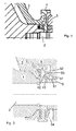
- Fig. 1 Schott al.
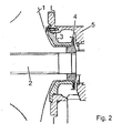
- Fig. 2 JP 2003-293783
- Fig. 1 Schott Controlled Sealing
- Fig. 2 JP 2003-293783
- the right-injecting oil is shielded by a co-rotating sealing disc from the sealing section.
- On the left side of the disc is through the sealing disc and the adjacent, fixed component a narrow gap formed, which prevents the oil by throttling and - during rotation - by return promotion at the inflow into the inner sealing area.
- the sealing of the oil chamber against blow-by is realized in both cases with labyrinths.
- the object of the invention is to improve the sealing of the storage space of turbochargers to the compressor rear space.
- the seal is extended by a catching chamber in the bearing housing, which is upstream of the rotating spray disk.
- the catching chamber consists of a groove in the standing part, which has a drain at the bottom.
- the trap chamber removes a large portion of the oil flow and thus reduces the amount of oil that impinges on the spray disk and the remainder of the seal, thereby improving the tightness.
- the seal comprises a kind of labyrinth, which is formed for example by at least one protruding nose and which prevents the oil from flowing along the sealing disc.
- the sealing system has a gutter in the stationary housing part, through which the sprayed-off oil is removed, so that it does not hit the rotating shaft once more.
- the shaft or a component mounted on the shaft, has a radially inner oil separator groove, from which the oil sprays radially outwards and then flows off through the bearing housing in the catching chamber in the stationary housing part.
- the labyrinth for sealing against blow-by through the sealing washer and the intermediate wall is formed.
- the heat input is reduced in the compressor, and the seal is more sensitive to strip because of the cheaper material pairing.
- the inventive seal according to Fig. 3 In contrast, it is extended by a catching chamber 51, which is connected upstream of the rotating sealing disk 4.
- the collecting chamber 51 extending along the circumference consists of a radially inwardly open groove in the stationary housing part 5, which has an oil drain 54 in the lower region.
- “Lower area” refers to gravity, so that the oil accumulates in the lower part of the catching chamber 51 and is discharged accordingly via the oil drain.
- the catching chamber 51 discharges a large part of the oil flow via the oil drain and thus reduces the quantity of oil which impinges on the sealing disk 4 and the remaining part of the seal, as a result of which the tightness is improved overall.
- the seal according to the invention has a kind of labyrinth.
- the maze includes according to Fig. 3 at least one projection 42 on the sealing disc 4, which extends in an opposite groove 53 in the fixed housing part 5.
- This labyrinth should prevent the oil from flowing along the sealing disc 4.
- It can also be provided a plurality of projections which extend in one or more wells.
- the projections may also be arranged on the housing side and extend in corresponding recesses in the sealing disc.
- the sealing system according to the invention has a catch groove 52, which is open radially outwards, in the stationary housing part 5, via which sprayed-off oil is removed, so that it does not strike the rotating shaft once more.
- the accumulated in the gutter 52 oil in turn runs in the lower part of the oil drain 54th
- further projections 41 may be provided in the area around the catching chamber.
- a trench 61 may be inserted, which enhances the effectiveness of the catching chamber.
- the sealing according to the invention of the storage space of turbochargers for the compressor wheel rear space comprises a labyrinth for sealing against blow-by.
- This labyrinth can be arranged between the sealing disk 4 and the intermediate wall 3. The displacement of the labyrinth away from the compressor wheel 1 reduces the heat input into the compressor wheel. In addition, the seal wins due to the cheaper material pairing to strip tolerance.
- the seal may be supplemented by another labyrinth or other seal between the compressor wheel and the stationary housing parts, such as the diaphragm, to further increase the effectiveness of the seal.
Landscapes
- Engineering & Computer Science (AREA)
- General Engineering & Computer Science (AREA)
- Mechanical Engineering (AREA)
- Supercharger (AREA)
- Sealing Using Fluids, Sealing Without Contact, And Removal Of Oil (AREA)
Description
- Die Erfindung bezieht sich auf das Gebiet der Abgasturbolader für aufgeladene Brennkraftmaschinen.
- Abgasturbolader werden zur Leistungssteigerung von Brennkraftmaschinen, insbesondere Hubkolbenmotoren, eingesetzt. Dabei besitzt ein Abgasturbolader üblicherweise einen Radialverdichter und eine Radial- oder Axialturbine. Zwischen der Turbine und dem Verdichter befindet sich das Lagergehäuse mit der Lagerung für die Welle.
- Die Abdichtung des Lagerraums zum Verdichterrad-Rückraum erfolgt bei herkömmlichen Abgasturboladern in der Regel durch eine berührungsfreie Wellendichtung. Die Dichtung hat zur Aufgabe, einerseits das aus den Lagern spritzende Schmieröl am Austritt in den Verdichterradrückraum zu hindern und andererseits den Luftmassenstrom vom Verdichterradrückraum in den Ölraum, den sogenannten ,Blow-by' zu minimieren.
- Die Ölabdichtung wird dadurch erschwert, dass beim Starten des Motors der Verdichter aufgrund der niedrigen Drehzahl nicht genügend Luft fördert, so dass im Verdichterkanal kurzzeitig ein leichter Unterdruck gegenüber dem Lagerraum entstehen kann. Bei höheren Drehzahlen hingegen herrscht im Verdichterradrückraum ein Überdruck gegenüber dem Ölraum.
- In
Fig. 1 (Schemaskizze eines ABB TPL Turboladers) undFig. 2 (JP 2003-293783 - Die Druckschrift
JP 2003-293783 - Die Aufgabe der Erfindung besteht darin, die Abdichtung des Lagerraums von Turboladern zum Verdichter-Rückraum zu verbessern.
- Dies erfolgt erfindungsgemäss dadurch, dass die Dichtung um eine Fangkammer im Lagergehäuse erweitert wird, welche der rotierenden Spritzscheibe vorgeschaltet ist. Die Fangkammer besteht aus einer Nut im stehenden Teil, welche im unteren Bereich einen Ablauf besitzt. Die Fangkammer führt einen grossen Teil des Ölstroms ab und reduziert so die Ölmenge, welche auf die Spritzscheibe und den restlichen Teil der Dichtung auftrifft, wodurch die Dichtheit verbessert wird.
- Anschliessend an die Fangkammer umfasst die Dichtung eine Art Labyrinth, welches beispielsweise durch mindestens eine hervorstehende Nase geformt ist und welches das Öl am Entlangströmen der Dichtscheibe hindert.
- Schliesslich verfügt das Dichtsystem über eine Fangrinne im stehenden Gehäuseteil, über welche abgespritztes Öl abgeführt wird, so dass es nicht ein weiteres Mal auf die rotierende Welle auftrifft.
- Optional weist die Welle, oder ein auf der Welle aufgesetztes Bauteil, eine radial innenliegende Ölabscheiderille auf, von welcher das Öl radial nach aussen abspritzt und anschliessend in der Fangkammer im stehenden Gehäuseteil durch das Lagergehäuse abfliesst.
- Optional wird das Labyrinth zur Abdichtung gegen Blow-by durch die Dichtscheibe und die Zwischenwand gebildet. Dadurch wird der Wärmeeintrag in das Verdichterrad verringert, und die Dichtung ist wegen der günstigeren Materialpaarung streiftoleranter.
- Im folgenden ist anhand der Figuren die erfindungsgemässe Vorrichtung schematisch dargestellt und näher erläutert.
- In allen Figuren sind gleichwirkende Elemente mit gleichen Bezugszeichen versehen:
- Fig. 1
- zeigt ein Schnittbild einer Abdichtung des Lagerraums von Turboladern zum Verdichter-Rückraum gemäss dem Stand der Technik,
- Fig. 2
- zeigt ein Schnittbild einer Abdichtung des Lagerraums von Turbotadern zum Verdichter-Rückraum gemäss dem Stand der Technik.
- Fig. 3
- zeigt ein Schnittbild einer erfindungsgemäss ausgebildeten Abdichtung des Lagerraums von Turboladern zum Verdichter-Rückraum mit einer Fangkammer.
- Wie Eingangs erwähnt, zeigen
Fig. 1 undFig. 2 herkömmliche Abdichtungen des Lagerraums von Turboladern zum Raum im Rücken des Verdichterrades 1. Der Raum im Rücken des Verdichterrades erstreckt sich zwischen dem Verdichterrad 1 und einem angrenzenden, feststehenden Gehäuseteil, der Zwischenwand 3. In beiden Fällen wird das von rechts zwischen dem feststehenden Gehäuseteil 5 und den mit der Welle 2 mitrotierenden Teilen anspritzende Öl durch eine mit der Welle 2 mitrotierende Dichtscheibe 4 von der Dichtpartie abgeschirmt. Auf der linken Seite der Dichtscheibe wird durch die Dichtscheibe und das angrenzende, feststehende Gehäuseteil, der Zwischenwand 3, ein schmaler Spalt ausgebildet, welcher das Öl durch Drosselung sowie - bei Rotation - durch Rückförderung am Einströmen in den inneren Dichtungsbereich hindert. Die Abdichtung des Ölraums gegen ,Blow-by' wird in beiden Fällen mit Labyrinthen zwischen der Zwischenwand 3 und dem Verdichterrad 1 realisiert. - Die erfindungsgemässe Dichtung gemäss
Fig. 3 ist demgegenüber um eine Fangkammer 51 erweitert, welche der rotierenden Dichtscheibe 4 vorgeschaltet ist. Die sich entlang dem Umfang erstreckende Fangkammer 51 besteht aus einer radial nach innen geöffneten Nut im stehenden Gehäuseteil 5, welche im unteren Bereich einen Ölablauf 54 besitzt. "Unterer Bereich" bezieht sich dabei auf die Schwerkraft, so dass sich das Öl im unteren Bereich der Fangkammer 51 ansammelt und entsprechend über den Ölablauf abgeführt wird. Die Fangkammer 51 führt über den Ölablauf einen grossen Teil des Ölstroms ab und reduziert so die Ölmenge, welche auf die Dichtscheibe 4 und den restlichen Teil der Dichtung auftrifft, wodurch insgesamt die Dichtheit verbessert wird. - Anschliessend an die Fangkammer besitzt die erfindungsgemässe Dichtung eine Art Labyrinth. Das Labyrinth umfasst gemäss
Fig. 3 mindestens ein Vorsprung 42 an der Dichtscheibe 4, welcher in einer gegenüberliegenden Nut 53 im feststehenden Gehäuseteil 5 verläuft. Dieses Labyrinth soll das Öl am Entlangströmen der Dichtscheibe 4 hindern. Es können auch mehrere Vorsprünge vorgesehen sein, welche in einer oder mehreren Vertiefung verlaufen. Die Vorsprünge können auch auf der Gehäuseseite angeordnet sein und in entsprechenden Vertiefungen in der Dichtscheibe verlaufen. - Schliesslich verfügt das erfindungsgemässe Dichtsystem über eine radial nach aussen geöffnete Fangrinne 52 im feststehenden Gehäuseteil 5, über welche abgespritztes Öl abgeführt wird, so dass es nicht ein weiteres Mal auf die rotierende Welle auftrifft. Das in der Fangrinne 52 angesammelte Öl läuft wiederum im unteren Bereich in den Ölablauf 54.
- Optional können im Bereich um die Fangkammer weitere Vorsprünge 41 vorgesehen sein. Auch kann in die Welle, bzw. in einem mit der Welle rotierenden Wellenaufsatz 6, ein Graben 61 eingelassen sein, welcher die Wirksamkeit der Fangkammer verstärkt.
- Optional umfasst die erfindungsgemässe Abdichtung des Lagerraums von Turboladern zum Verdichterrad-Rückraum ein Labyrinth zur Abdichtung gegen Blow-by. Dieses Labyrinth kann zwischen der Dichtscheibe 4 und der Zwischenwand 3 angeordnet sein. Die Verschiebung des Labyrinths weg vom Verdichterrad 1 verringert den Wärmeeintrag in das Verdichterrad. Zudem gewinnt die Dichtung aufgrund der günstigeren Materialpaarung an Streiftoleranz.
- Optional kann die Dichtung durch ein weiteres Labyrinth oder eine andere Dichtung zwischen dem Verdichterrad und den stehenden Gehäuseteilen, beispielsweise der Zwischenwand, ergänzt werden, um die Wirksamkeit der Abdichtung weiter zu erhöhen.
-
- 1
- Verdichterrad
- 2
- Welle
- 3
- Zwischenwand
- 31
- Labyrinth zwischen Zwischenwand und Dichtscheibe
- 4
- Dichtscheibe
- 41, 42
- Vorsprung an Dichtscheibe
- 5
- Lagergehäuse
- 51
- Fangkammer
- 52
- Fangrinne
- 53
- Vertiefung
- 54
- Ölablauf
- 6
- Wellenaufsatz
- 61
- Graben in Wellenaufsatz
Claims (9)
- Abdichtung des Raums im Rücken eines Verdichterrades (1) gegenüber mit Öl beaufschlagten Lagerraum in einem Lagergehäuse, in welchem Lagergehäuse eine Welle (2) drehbar gelagert ist, wobei die Abdichtung eine mit der Welle (2) verbundene Dichtscheibe (4) umfasst, dadurch gekennzeichnet, dass zwischen dem Lagerraum und der Dichtscheibe (4) in das Lagergehäuse (5) eine umlaufende, radial nach innen geöffnete Nut eingelassen ist, welche zusammen mit der Welle (2) eine Fangkammer (51) bildet.
- Abdichtung nach Anspruch 1, wobei in die Welle, oder in einen mit der Welle rotierenden Aufsatz (6), ein die Fangkammer radial nach innen erweiternden Graben (61) eingelassen ist.
- Abdichtung nach Anspruch 1 oder 2, wobei um unteren Bereich der Fangkammer (51) ein Ölablauf (54) vorgesehen ist.
- Abdichtung nach Anspruch 1, wobei die Dichtscheibe (4) und das Lagergehäuse (5) sich gegenüberliegende Bereiche aufweisen und in diesen Bereichen mindestens ein Vorsprung (42) und mindestens eine Vertiefung (53) vorgesehen sind, wobei der Vorsprung (42) in der Vertiefung (53) verläuft und Vorsprung (42) und Vertiefung (53) ein Labyrinth bilden.
- Abdichtung nach einem der Ansprüche 1 bis 4, wobei zwischen der Dichtscheibe (4) und dem Lagergehäuse (5) im Lagergehäuse (5) eine umlaufende, radial nach aussen geöffnete Fangrille (52) angeordnet ist.
- Abdichtung nach Anspruch 5, wobei um unteren Bereich der Fangkammer (51) ein Ölablauf (54) vorgesehen ist und die Fangrille (52) im unteren Bereich ebenfalls in den Ölablauf (54) mündet.
- Abdichtung nach einem der vorangehenden Ansprüche, wobei zwischen der Dichtscheibe (4) und dem zusammen mit dem Verdichterrad (1) den Raum im Rücken des Verdichterrades begrenzenden Gehäuseteil (3) eine Labyrinthdichtung (31) vorgesehen ist.
- Abdichtung nach einem der vorangehenden Ansprüche, wobei zwischen dem Verdichterrad (1) und dem zusammen mit dem Verdichterrad (1) den Raum im Rücken des Verdichterrades begrenzenden Gehäuseteil (3) eine Labyrinthdichtung vorgesehen ist.
- Abgasturbolader, mit einer Abdichtung des Verdichterrückraums gegenüber dem Ölraum nach einem der vorangehenden Ansprüche.
Priority Applications (1)
| Application Number | Priority Date | Filing Date | Title |
|---|---|---|---|
| EP07819965A EP2054629B1 (de) | 2006-08-24 | 2007-08-24 | Wellenabdichtung |
Applications Claiming Priority (4)
| Application Number | Priority Date | Filing Date | Title |
|---|---|---|---|
| EP06405361 | 2006-08-24 | ||
| EP06023405 | 2006-11-10 | ||
| EP07819965A EP2054629B1 (de) | 2006-08-24 | 2007-08-24 | Wellenabdichtung |
| PCT/EP2007/058825 WO2008023061A1 (de) | 2006-08-24 | 2007-08-24 | Wellenabdichtung |
Publications (2)
| Publication Number | Publication Date |
|---|---|
| EP2054629A1 EP2054629A1 (de) | 2009-05-06 |
| EP2054629B1 true EP2054629B1 (de) | 2009-12-09 |
Family
ID=38941874
Family Applications (1)
| Application Number | Title | Priority Date | Filing Date |
|---|---|---|---|
| EP07819965A Active EP2054629B1 (de) | 2006-08-24 | 2007-08-24 | Wellenabdichtung |
Country Status (6)
| Country | Link |
|---|---|
| EP (1) | EP2054629B1 (de) |
| JP (1) | JP2010501772A (de) |
| KR (1) | KR101344179B1 (de) |
| CN (1) | CN101506529B (de) |
| DE (1) | DE502007002291D1 (de) |
| WO (1) | WO2008023061A1 (de) |
Families Citing this family (4)
| Publication number | Priority date | Publication date | Assignee | Title |
|---|---|---|---|---|
| EP2516047B1 (de) * | 2009-12-22 | 2015-10-07 | Basf Se | Dichtanordnung für einen prozessgasturboverdichter |
| JP6195308B2 (ja) * | 2014-06-25 | 2017-09-13 | 三菱重工業株式会社 | 軸流タービンのラビリンスシール装置およびこれを備えた排ガスタービン過給機 |
| DE102014011849A1 (de) * | 2014-08-08 | 2016-02-11 | Man Diesel & Turbo Se | Wellendichtungssystem und Abgasturbolader |
| KR102551115B1 (ko) * | 2018-08-08 | 2023-07-05 | 엘지전자 주식회사 | 원심압축기 |
Family Cites Families (5)
| Publication number | Priority date | Publication date | Assignee | Title |
|---|---|---|---|---|
| CH336660A (de) | 1954-10-18 | 1959-02-28 | Vickers Electrical Co Ltd | Labyrinthgasdichtung |
| FR2357760A1 (fr) | 1976-07-06 | 1978-02-03 | Mecanique Ind Int | Perfectionnements aux pompes centrifuges |
| DE3247980C1 (de) * | 1982-12-24 | 1987-08-20 | Goetze Ag, 5093 Burscheid | Verfahren zum Einstellen der axialen Federkraft einer mit einem Laufrad verbundenen Gleitringdichtung sowie nach diesem Verfahren hergestellte und gepruefte Einbaueinheit |
| JP2001289052A (ja) * | 2000-04-03 | 2001-10-19 | Suzuki Motor Corp | ターボ過給機 |
| JP2003293783A (ja) * | 2002-04-02 | 2003-10-15 | Mitsubishi Heavy Ind Ltd | 過給機の油シール装置 |
-
2007
- 2007-08-24 DE DE502007002291T patent/DE502007002291D1/de active Active
- 2007-08-24 WO PCT/EP2007/058825 patent/WO2008023061A1/de not_active Ceased
- 2007-08-24 EP EP07819965A patent/EP2054629B1/de active Active
- 2007-08-24 JP JP2009525078A patent/JP2010501772A/ja active Pending
- 2007-08-24 CN CN2007800315298A patent/CN101506529B/zh active Active
- 2007-08-24 KR KR1020097003030A patent/KR101344179B1/ko active Active
Also Published As
| Publication number | Publication date |
|---|---|
| WO2008023061A1 (de) | 2008-02-28 |
| CN101506529B (zh) | 2011-02-02 |
| CN101506529A (zh) | 2009-08-12 |
| EP2054629A1 (de) | 2009-05-06 |
| JP2010501772A (ja) | 2010-01-21 |
| KR20090042793A (ko) | 2009-04-30 |
| DE502007002291D1 (de) | 2010-01-21 |
| KR101344179B1 (ko) | 2013-12-20 |
Similar Documents
| Publication | Publication Date | Title |
|---|---|---|
| EP2192272B1 (de) | Vorrichtung zum Abdichten eines Lagergehäuses eines Abgasturboladers | |
| EP2375000B1 (de) | Wellenabdichtung | |
| DE112013002029T5 (de) | Schleuderscheiben-Öldichtung und Turbolader mit Schleuderscheiben-Öldichtung | |
| EP3392471B1 (de) | Lagergehäuse und ein abgasturbolader mit einem solchen gehäuse | |
| EP2054629B1 (de) | Wellenabdichtung | |
| DE102016111855A1 (de) | Ölverteilungssystem und Turbomaschine mit einem Ölverteilungssystem | |
| DE102013202841A1 (de) | Abgasturbolader | |
| EP2743460B1 (de) | Wellenabdichtung | |
| EP2772652B1 (de) | Zwischenwand zur Abdichtung des Rückraums eines Radialverdichters | |
| EP2112332B1 (de) | Trägerring einer Leitvorrichtung mit Sperrluftkanal | |
| EP3374602B1 (de) | Vorrichtung zur abdichtung eines lagergehäuses und abgasturbolader mit einer solchen vorrichtung | |
| WO2014131413A1 (de) | Dichtungsanordnung für eine turboladerwelle eines abgasturboladers | |
| EP1673519B1 (de) | Dichtungsanordnung für eine gasturbine | |
| DE102004009412B4 (de) | Abgasturbolader | |
| DE102016004770B4 (de) | Anschlaganordnung, Ansaug- und Abgasanlage und Fahrzeug umfassend solch eine Anlage | |
| DE102010038524A1 (de) | Turbomaschine | |
| EP1998023B1 (de) | Ladeeinrichtung | |
| EP3371420B1 (de) | Vorrichtung zur trennung von schmierölströmen und abgasturbolader mit einer solchen vorrichtung | |
| DE102012011144A1 (de) | Hydraulische Dichtungsanordnung | |
| EP1388646B1 (de) | Einrichtung zum Entlüften eines Kurbelgehäuses | |
| EP3867501B1 (de) | Abgasturbolader mit verbesserter wellendichtung | |
| EP2568187B1 (de) | Gehäuseanordnung | |
| DE102006033560B4 (de) | Gleitlageranordnung | |
| DE102019219090A1 (de) | Dichtungsträger für eine Turbomaschine mit schlitzartigen Öffnungen im Dichtungskörper | |
| WO2008055999A1 (de) | Verdichter |
Legal Events
| Date | Code | Title | Description |
|---|---|---|---|
| PUAI | Public reference made under article 153(3) epc to a published international application that has entered the european phase |
Free format text: ORIGINAL CODE: 0009012 |
|
| 17P | Request for examination filed |
Effective date: 20090217 |
|
| AK | Designated contracting states |
Kind code of ref document: A1 Designated state(s): AT BE BG CH CY CZ DE DK EE ES FI FR GB GR HU IE IS IT LI LT LU LV MC MT NL PL PT RO SE SI SK TR |
|
| AX | Request for extension of the european patent |
Extension state: AL BA HR MK RS |
|
| RIN1 | Information on inventor provided before grant (corrected) |
Inventor name: SCHOENBAECHLER, FABIAN Inventor name: NEUENSCHWANDER, PETER Inventor name: KIES, MATTHIAS Inventor name: AMMANN, BRUNO Inventor name: DI PIETRO, MARCO |
|
| GRAP | Despatch of communication of intention to grant a patent |
Free format text: ORIGINAL CODE: EPIDOSNIGR1 |
|
| DAX | Request for extension of the european patent (deleted) | ||
| RBV | Designated contracting states (corrected) |
Designated state(s): DE GB |
|
| GRAS | Grant fee paid |
Free format text: ORIGINAL CODE: EPIDOSNIGR3 |
|
| GRAA | (expected) grant |
Free format text: ORIGINAL CODE: 0009210 |
|
| AK | Designated contracting states |
Kind code of ref document: B1 Designated state(s): DE GB |
|
| REG | Reference to a national code |
Ref country code: GB Ref legal event code: FG4D Free format text: NOT ENGLISH |
|
| REF | Corresponds to: |
Ref document number: 502007002291 Country of ref document: DE Date of ref document: 20100121 Kind code of ref document: P |
|
| PLBE | No opposition filed within time limit |
Free format text: ORIGINAL CODE: 0009261 |
|
| STAA | Information on the status of an ep patent application or granted ep patent |
Free format text: STATUS: NO OPPOSITION FILED WITHIN TIME LIMIT |
|
| 26N | No opposition filed |
Effective date: 20100910 |
|
| REG | Reference to a national code |
Ref country code: DE Ref legal event code: R081 Ref document number: 502007002291 Country of ref document: DE Owner name: TURBO SYSTEMS SWITZERLAND LTD., CH Free format text: FORMER OWNER: ABB TURBO SYSTEMS AG, BADEN, CH Ref country code: DE Ref legal event code: R082 Ref document number: 502007002291 Country of ref document: DE Representative=s name: ZIMMERMANN & PARTNER PATENTANWAELTE MBB, DE Ref country code: DE Ref legal event code: R081 Ref document number: 502007002291 Country of ref document: DE Owner name: ABB SCHWEIZ AG, CH Free format text: FORMER OWNER: ABB TURBO SYSTEMS AG, BADEN, CH |
|
| REG | Reference to a national code |
Ref country code: GB Ref legal event code: 732E Free format text: REGISTERED BETWEEN 20210225 AND 20210303 |
|
| REG | Reference to a national code |
Ref country code: GB Ref legal event code: 732E Free format text: REGISTERED BETWEEN 20210304 AND 20210310 |
|
| REG | Reference to a national code |
Ref country code: GB Ref legal event code: 732E Free format text: REGISTERED BETWEEN 20220922 AND 20220928 |
|
| REG | Reference to a national code |
Ref country code: DE Ref legal event code: R081 Ref document number: 502007002291 Country of ref document: DE Owner name: TURBO SYSTEMS SWITZERLAND LTD., CH Free format text: FORMER OWNER: ABB SCHWEIZ AG, BADEN, CH Ref country code: DE Ref legal event code: R081 Ref document number: 502007002291 Country of ref document: DE Owner name: ACCELLERON SWITZERLAND LTD., CH Free format text: FORMER OWNER: ABB SCHWEIZ AG, BADEN, CH |
|
| REG | Reference to a national code |
Ref country code: DE Ref legal event code: R081 Ref document number: 502007002291 Country of ref document: DE Owner name: ACCELLERON SWITZERLAND LTD., CH Free format text: FORMER OWNER: TURBO SYSTEMS SWITZERLAND LTD., BADEN, CH |
|
| PGFP | Annual fee paid to national office [announced via postgrant information from national office to epo] |
Ref country code: DE Payment date: 20250820 Year of fee payment: 19 |
|
| PGFP | Annual fee paid to national office [announced via postgrant information from national office to epo] |
Ref country code: GB Payment date: 20250820 Year of fee payment: 19 |