EP2053372A2 - Vorrichtung und Verfahren zur Druckmessung unter Verwendung von magnetostriktiven elektrischen Leitern - Google Patents
Vorrichtung und Verfahren zur Druckmessung unter Verwendung von magnetostriktiven elektrischen Leitern Download PDFInfo
- Publication number
- EP2053372A2 EP2053372A2 EP08166103A EP08166103A EP2053372A2 EP 2053372 A2 EP2053372 A2 EP 2053372A2 EP 08166103 A EP08166103 A EP 08166103A EP 08166103 A EP08166103 A EP 08166103A EP 2053372 A2 EP2053372 A2 EP 2053372A2
- Authority
- EP
- European Patent Office
- Prior art keywords
- wire
- fluid
- sensor assembly
- chamber
- stress
- Prior art date
- Legal status (The legal status is an assumption and is not a legal conclusion. Google has not performed a legal analysis and makes no representation as to the accuracy of the status listed.)
- Withdrawn
Links
- 239000004020 conductor Substances 0.000 title claims description 12
- 238000000034 method Methods 0.000 title description 2
- 239000012530 fluid Substances 0.000 claims abstract description 38
- 239000000758 substrate Substances 0.000 claims description 15
- 239000007787 solid Substances 0.000 claims description 9
- 230000002706 hydrostatic effect Effects 0.000 claims description 6
- 230000019491 signal transduction Effects 0.000 claims description 2
- 230000000149 penetrating effect Effects 0.000 claims 2
- 239000000463 material Substances 0.000 description 10
- PXHVJJICTQNCMI-UHFFFAOYSA-N Nickel Chemical compound [Ni] PXHVJJICTQNCMI-UHFFFAOYSA-N 0.000 description 8
- 230000004907 flux Effects 0.000 description 8
- 229910052759 nickel Inorganic materials 0.000 description 3
- 229910000640 Fe alloy Inorganic materials 0.000 description 2
- 239000004593 Epoxy Substances 0.000 description 1
- 229910001030 Iron–nickel alloy Inorganic materials 0.000 description 1
- 229910001240 Maraging steel Inorganic materials 0.000 description 1
- 229910000990 Ni alloy Inorganic materials 0.000 description 1
- 229910000831 Steel Inorganic materials 0.000 description 1
- 239000000919 ceramic Substances 0.000 description 1
- 238000002485 combustion reaction Methods 0.000 description 1
- 230000005284 excitation Effects 0.000 description 1
- 239000000446 fuel Substances 0.000 description 1
- 239000011521 glass Substances 0.000 description 1
- 239000011810 insulating material Substances 0.000 description 1
- 238000009413 insulation Methods 0.000 description 1
- UGKDIUIOSMUOAW-UHFFFAOYSA-N iron nickel Chemical compound [Fe].[Ni] UGKDIUIOSMUOAW-UHFFFAOYSA-N 0.000 description 1
- 239000000696 magnetic material Substances 0.000 description 1
- 238000005259 measurement Methods 0.000 description 1
- 238000004806 packaging method and process Methods 0.000 description 1
- 230000035699 permeability Effects 0.000 description 1
- 230000000704 physical effect Effects 0.000 description 1
- 229920000642 polymer Polymers 0.000 description 1
- 238000007789 sealing Methods 0.000 description 1
- 239000010959 steel Substances 0.000 description 1
Images

Classifications
-
- G—PHYSICS
- G01—MEASURING; TESTING
- G01L—MEASURING FORCE, STRESS, TORQUE, WORK, MECHANICAL POWER, MECHANICAL EFFICIENCY, OR FLUID PRESSURE
- G01L9/00—Measuring steady of quasi-steady pressure of fluid or fluent solid material by electric or magnetic pressure-sensitive elements; Transmitting or indicating the displacement of mechanical pressure-sensitive elements, used to measure the steady or quasi-steady pressure of a fluid or fluent solid material, by electric or magnetic means
- G01L9/16—Measuring steady of quasi-steady pressure of fluid or fluent solid material by electric or magnetic pressure-sensitive elements; Transmitting or indicating the displacement of mechanical pressure-sensitive elements, used to measure the steady or quasi-steady pressure of a fluid or fluent solid material, by electric or magnetic means by making use of variations in the magnetic properties of material resulting from the application of stress
Definitions
- the present invention relates generally to magnetostrictive (MS) stress sensors.
- Magnetostrictive stress sensors can be used to measure stress such as might be imposed on the sensor by fluid pressure.
- an MS stress sensor includes a core made of an MS material, such as a nickel-iron alloy and a coil surrounding the core for establishing axial magnetic AC flux within the core.
- a magnetic flux carrier made of either MS or non-MS material can be employed provide a return path for the magnetic flux for improved sensor performance.
- the permeability of the MS core, and thus the impedance of the coil is a function of stress applied to the core in alignment with the magnetic flux in the core. The coil impedance therefore provides a signal that represents the magnitude of the stress within the core and, hence, is the magnitude of the physical effect causing the stress, such as fluid pressure on the core.
- the AC magnetic flux within the MS core can be generated without the use of a flux generating coil surrounding the core, simply by forcing the excitation current to flow directly through the core.
- This concept is disclosed in the present assignee's co-pending U.S. patent applications nos. 11/244792 ; 11/064580 ; 11/280923 ; and 11/713961 , incorporated herein by reference.
- the magnetic flux is to a large degree confined within the MS core, which can be in the shape of a wire, but does not need to have the form of a coil, except for the purpose of compact packaging.
- This coil-less MS stress sensor Large signals are obtained, because the entire core is subjected to stress.
- a wire shaped core made of MS material conducting AC current, which generates an AC magnetic field within the core can be provided for the purpose of measuring stress including hydrostatic stress acting upon the core.
- the present invention understands that such a core, to be useful as a sensor of fluid pressure, must be appropriately juxtaposed with the fluid.
- a sensor assembly has a sensor housing forming a fluid chamber and a magnetostrictive wire that undergoes stress due to stress induced by fluid in the chamber.
- the wire defines opposed ends, each being associated with a respective terminal.
- Respective hermetic seals penetrate the housing and are coupled to the respective terminals.
- the wire can be disposed in fluid in the chamber without support structure between opposed ends of the wire.
- the wire can be solid or hollow.
- the wire can be disposed in fluid in the chamber and can be wound around a supporting core.
- the wire can be disposed in fluid in the chamber and can be flush against a supporting substrate that may if desired be juxtaposed with at least one cover to sense hydrostatic stress.
- a sensor assembly has a sensor housing forming a fluid chamber, and a magnetostrictive wire undergoes stress induced by fluid in the chamber.
- First and second sealed openings in the housing provide signal pathways to first and second parts of the wire.
- a sensor for outputting a signal representative of stress caused by a source of stress.
- the sensor includes housing means and magnetostrictive (MS) wire means in the housing means andjuxtaposable with the source of stress such that the source of stress causes stress in the MS means.
- Seal means penetrate the housing means for providing a signal path to the MS wire means.
- Figure 1 shows a system in accordance with one non-limiting embodiment of the present invention
- Figure 2 is a partial cross-sectional view of a MS wire loop in one example environment
- Figure 3 is a partial cross-sectional view of a MS wire loop in another example environment
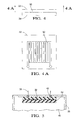
- Figure 4 shows a MS wire in a planar configuration, showing the substrate bearing the MS wire in side elevation sandwiched between the cover and substrate;
- Figure 4A is a top plan view of the embodiment shown in Figure 4 ;
- Figure 5 is a side view of the embodiment of Figure 4 , showing the substrate disposed in a sensor housing.
- the MS stress sensor 10 can be coupled to a source of pressure, such as to a fluid container 12, with the MS stress sensor 10 having the ability to sense fluid pressure (hydrostatic stress) in the fluid container 12 in accordance with principles below.
- a source of pressure such as to a fluid container 12
- the fluid container 12 may be, e.g., a vehicle fuel rail, a brake fluid tank, combustion chamber, etc., although present principles are not limited to any particular fluid application.
- the MS stress sensor 10 is also electronically connected to a computer 14 which may be, without limitation, an engine control module.
- the computer 14 receives the signal that is output by the sensor 10 for processing the signal to, e.g., correlate the stress as indicated by the signal to a fluid pressure. Further, the computer 14 may be electronically connected to a component 16 such as a fluid pump that may be controlled by the computer 14 based on data received from the MS stress sensor 10.
- the senor 10 is shown to include a hollow housing 17 that supports coil 18 of a magnetostrictive wire.
- Wire as used herein means an elongated electrical conductor with preferably, although not necessarily, a circular cross-section.
- each seal 20 can be formed with a conically-shaped opening through which a terminal ends 18a, 18b, which can be made of the same magnetostrictive material as the coil, to which it is connected.
- the opening can be filled with, e.g., epoxy after assembly.
- the coil 18 can be made without structural supports between opposed ends or adjacent loops, by the selection of sufficiently thick wire.
- terminal ends 18a, 18b While two separate openings are shown for respective terminal ends 18a, 18b, it is to be understood that both terminal ends 18a, 18b, with appropriate insulation, can extend through a single common opening with a single hermetic seal 20.
- the inductance of the coil 18 is proportional to the length of the MS wire, making it advantageous to have a relatively longer wire in order to facilitate measurement.
- the ends of the coil 18 may extend through the seals or may be engaged with separate terminal leads that extend through the seals 20.
- the coil 18 shown in Figure 2 there are two embodiments for the coil 18 shown in Figure 2 : solid and hollow.
- the terminal ends 18a, 18b can be internally sealed, before being connected to the seals 20, so that no pressurized fluid 22 in the sensor housing 17 can leak into the interior of the MS wire forming coil 18.
- the inner volume of the (hollow) wire coil 18 may either be pressurized to standard atmospheric pressure or evacuated. Both inner and outer surfaces of the hollow embodiment preferably define concentric circles in cross-section.
- the MS wire When the MS wire is hollow, it can more easily be contracted than its solid form, making it more sensitive. However, when solid wire is used to form the coil 18, the coil 18 can withstand pressures beyond the expected yielding point of its material. In both cases, the coil 18 may be coated with or housed within an insulating material to avoid short-circuits from one part of the coil 18 to another.
- the wire may have a rectangular cross-section particularly when solid, or other cross-sections may be used, e.g., trapezoidal.
- a solid rectangular conductor can be used for deviatoric stress sensing applications, e.g., for use as a brake force sensor.
- the sensor housing 17 is distinct from the wall 19 holding the pressurized fluid. It is also contemplated that the MS wires can be mounted directly on the walls 19 of the fluid reservoir. That is, housing 17 and wall 19 are then one part serving two functions, housing for the sensor and wall for the fluid reservoir, tank, etc. "Housing”, therefore, must be understood as any structure serving the function of holding the sensor, as well as possibly other functions.
- Figure 3 shows a third embodiment that is in all essential respects identical to the embodiments shown in Figure 2 , except that a magnetostrictive coil 23 is wound around a solid supporting bobbin 24.
- the bobbin 24 can be generally cylindrical or slightly conical and can be made from an electrically non-conducting, and preferably non-magnetic, material.
- Figure 3 shows that the bobbin 24 can provide further sealing of the terminal ends 18a, 18b because its upper surface 24a can abut the upper inside surface 17a of the sensor housing.
- Figures 4 and 5 present a planar embodiment of a support structure for an MS wire.
- a MS wire 30 is disposed onto a flat substrate 32 and a respective flat cover 34 is laid over the wire 18.
- the substrate 32 may be sandwiched between two covers if desired.
- the wire 30 can be configured as a coil on the substrate 32 or in another pattern such as the non-limiting staggered straight line configuration shown in Figures 4 and 4A .
- the cover 34 is placed over the wire 18 in such a way that allows for free fluid flow between the substrate 26 and cover 34, and possibly within the cover 34 itself, it being understood that the cover 34 may be omitted in some embodiments.
- the substrate 32 and cover 34 may be made from electrically non-conducting and non-magnetic material.
- the support in the form of the substrate 32 and cover 34 is advantageous in that it is manufactured with a greater ease than the bobbin 24.
- terminals 36 are engaged with or formed integrally with respective ends of the wire 30 and rise perpendicularly away from the substrate 32.
- the substrate 32 and, when provided, cover 34 may be disposed in a hollow sensor housing 38 holding a fluid 40 whose pressure is to be sensed.
- the terminals 36 extend through respective hermetic seals 42 in the housing 38 in a manner as described above.
- the materials used for the MS wire may include but are not limited to nickel/iron alloys, pure nickel, galfenol, that is, any material that is both magnetostrictive and electrically conductive.
- Preferred non-limiting materials include maraging steel (steel with about 18% nickel content) and nickel-iron alloys with 30%-70% nickel content.
Landscapes
- Physics & Mathematics (AREA)
- General Physics & Mathematics (AREA)
- Measuring Fluid Pressure (AREA)
Applications Claiming Priority (1)
| Application Number | Priority Date | Filing Date | Title |
|---|---|---|---|
| US11/977,322 US20090107249A1 (en) | 2007-10-24 | 2007-10-24 | Means and method of sensing pressure using magnetostrictive electrical condutors |
Publications (2)
| Publication Number | Publication Date |
|---|---|
| EP2053372A2 true EP2053372A2 (de) | 2009-04-29 |
| EP2053372A3 EP2053372A3 (de) | 2010-08-04 |
Family
ID=40263551
Family Applications (1)
| Application Number | Title | Priority Date | Filing Date |
|---|---|---|---|
| EP08166103A Withdrawn EP2053372A3 (de) | 2007-10-24 | 2008-10-08 | Vorrichtung und Verfahren zur Druckmessung unter Verwendung von magnetostriktiven elektrischen Leitern |
Country Status (2)
| Country | Link |
|---|---|
| US (1) | US20090107249A1 (de) |
| EP (1) | EP2053372A3 (de) |
Families Citing this family (3)
| Publication number | Priority date | Publication date | Assignee | Title |
|---|---|---|---|---|
| US7816797B2 (en) * | 2009-01-07 | 2010-10-19 | Oscilla Power Inc. | Method and device for harvesting energy from ocean waves |
| US20120086205A1 (en) * | 2010-10-08 | 2012-04-12 | Balakrishnan Nair | Method and device for harvesting energy from ocean waves |
| GB2489244B (en) | 2011-03-22 | 2013-12-18 | Norsk Titanium Components As | Method for production of alloyed titanium welding wire |
Citations (4)
| Publication number | Priority date | Publication date | Assignee | Title |
|---|---|---|---|---|
| US64580A (en) | 1867-05-07 | david schbbtz and beuben adams | ||
| US20070080680A1 (en) | 2005-10-06 | 2007-04-12 | Thaddeus Schroeder | Apparatus, sensor, and method for measuring an amount of strain |
| US20070107528A1 (en) | 2005-11-16 | 2007-05-17 | Thaddeus Schroeder | Versatile strain sensor employing magnetostrictive electrical conductors |
| US20080216582A1 (en) | 2007-03-05 | 2008-09-11 | Oberdier Larry M | Apparatus, system and method for measuring stress |
Family Cites Families (10)
| Publication number | Priority date | Publication date | Assignee | Title |
|---|---|---|---|---|
| US4140044A (en) * | 1976-07-30 | 1979-02-20 | The Singer Company | Long stroke, large bore, low friction hydraulic actuators |
| US4142079A (en) * | 1978-02-09 | 1979-02-27 | Delaval Turbine Inc. | Float-level switch with lifting mechanism |
| JPS6022287B2 (ja) * | 1980-07-17 | 1985-06-01 | 松下電器産業株式会社 | 圧力センサ |
| US4495821A (en) * | 1983-01-31 | 1985-01-29 | General Electric Company | Magnetostrictive pressure detector |
| US5551312A (en) * | 1992-07-02 | 1996-09-03 | Masson; Guy | Device for sampling and pumping liquids contained in a chemical reaction vessel, drum or storage tank |
| US5535625A (en) * | 1994-03-14 | 1996-07-16 | Magnetek, Inc. | Integrated liquid level and auxiliary sensor system and method |
| US6192752B1 (en) * | 1995-08-04 | 2001-02-27 | Zevex, Inc. | Noninvasive electromagnetic fluid level sensor |
| JP2000292294A (ja) * | 1999-04-05 | 2000-10-20 | Tokin Corp | 密閉容器の内部圧力検出用センサ |
| US6960911B2 (en) * | 2002-01-29 | 2005-11-01 | Kabushiki Kaisha Toshiba | Strain sensor |
| US6978833B2 (en) * | 2003-06-02 | 2005-12-27 | Schlumberger Technology Corporation | Methods, apparatus, and systems for obtaining formation information utilizing sensors attached to a casing in a wellbore |
-
2007
- 2007-10-24 US US11/977,322 patent/US20090107249A1/en not_active Abandoned
-
2008
- 2008-10-08 EP EP08166103A patent/EP2053372A3/de not_active Withdrawn
Patent Citations (4)
| Publication number | Priority date | Publication date | Assignee | Title |
|---|---|---|---|---|
| US64580A (en) | 1867-05-07 | david schbbtz and beuben adams | ||
| US20070080680A1 (en) | 2005-10-06 | 2007-04-12 | Thaddeus Schroeder | Apparatus, sensor, and method for measuring an amount of strain |
| US20070107528A1 (en) | 2005-11-16 | 2007-05-17 | Thaddeus Schroeder | Versatile strain sensor employing magnetostrictive electrical conductors |
| US20080216582A1 (en) | 2007-03-05 | 2008-09-11 | Oberdier Larry M | Apparatus, system and method for measuring stress |
Also Published As
| Publication number | Publication date |
|---|---|
| EP2053372A3 (de) | 2010-08-04 |
| US20090107249A1 (en) | 2009-04-30 |
Similar Documents
| Publication | Publication Date | Title |
|---|---|---|
| CN101561301B (zh) | 电磁流量计 | |
| US9310229B2 (en) | Sensor system and method for manufacturing a sensor system | |
| CA2404468C (en) | Sensor apparatus with two resonant transducers and a single conductor | |
| CN102798333B (zh) | 传感器及传感器的制造方法 | |
| US7036385B2 (en) | Pressure sensor and related method | |
| US9348043B2 (en) | Multi-coil multi-terminal closed-loop geophone accelerometer | |
| EP2053372A2 (de) | Vorrichtung und Verfahren zur Druckmessung unter Verwendung von magnetostriktiven elektrischen Leitern | |
| US9238251B2 (en) | Dual-coil geophone accelerometer | |
| JPH06180264A (ja) | 導線引出し部の封止構造及びこの封止構造を有するプラグ | |
| US7466124B2 (en) | Magnetostrictive transmitter with improved piezoelectric sensor | |
| CN107608000A (zh) | 一种质子磁力仪的探头 | |
| CN103995287B (zh) | 单点垂直地震检波器 | |
| JPH03237332A (ja) | 半導体圧力センサ | |
| CN1334917A (zh) | 感应压力传感器 | |
| CN219870100U (zh) | 压力传感器模块和压力测量装置 | |
| JP2008203117A (ja) | 物理量測定モジュールおよび物理量測定器 | |
| EP4053529B1 (de) | Vorrichtung zur messung des wasserdrucks in bodenporen mit einem druckmesser | |
| CN120947699B (zh) | 一种耐高压传感器及其制备方法 | |
| CN222393692U (zh) | 压力传感器 | |
| RU2308704C2 (ru) | Датчик контроля коррозионной активности среды | |
| CN216361790U (zh) | 一种用于岩心监测的岩心夹持装置 | |
| JP6969832B1 (ja) | ひずみゲージ式変換器 | |
| WO2022255156A1 (ja) | ひずみゲージ式変換器 | |
| CN2275118Y (zh) | 敞开型断电式传压盒 | |
| CN118169480A (zh) | Mems大气电场传感器及其组装方法 |
Legal Events
| Date | Code | Title | Description |
|---|---|---|---|
| PUAI | Public reference made under article 153(3) epc to a published international application that has entered the european phase |
Free format text: ORIGINAL CODE: 0009012 |
|
| AK | Designated contracting states |
Kind code of ref document: A2 Designated state(s): AT BE BG CH CY CZ DE DK EE ES FI FR GB GR HR HU IE IS IT LI LT LU LV MC MT NL NO PL PT RO SE SI SK TR |
|
| AX | Request for extension of the european patent |
Extension state: AL BA MK RS |
|
| PUAL | Search report despatched |
Free format text: ORIGINAL CODE: 0009013 |
|
| AK | Designated contracting states |
Kind code of ref document: A3 Designated state(s): AT BE BG CH CY CZ DE DK EE ES FI FR GB GR HR HU IE IS IT LI LT LU LV MC MT NL NO PL PT RO SE SI SK TR |
|
| AX | Request for extension of the european patent |
Extension state: AL BA MK RS |
|
| AKY | No designation fees paid | ||
| REG | Reference to a national code |
Ref country code: DE Ref legal event code: R108 Effective date: 20110315 Ref country code: DE Ref legal event code: 8566 |
|
| STAA | Information on the status of an ep patent application or granted ep patent |
Free format text: STATUS: THE APPLICATION IS DEEMED TO BE WITHDRAWN |
|
| 18D | Application deemed to be withdrawn |
Effective date: 20110205 |