EP2053179A1 - Dämmstofhalter - Google Patents
Dämmstofhalter Download PDFInfo
- Publication number
- EP2053179A1 EP2053179A1 EP08018441A EP08018441A EP2053179A1 EP 2053179 A1 EP2053179 A1 EP 2053179A1 EP 08018441 A EP08018441 A EP 08018441A EP 08018441 A EP08018441 A EP 08018441A EP 2053179 A1 EP2053179 A1 EP 2053179A1
- Authority
- EP
- European Patent Office
- Prior art keywords
- transfer body
- sealing surface
- insulation holder
- head
- receiving part
- Prior art date
- Legal status (The legal status is an assumption and is not a legal conclusion. Google has not performed a legal analysis and makes no representation as to the accuracy of the status listed.)
- Granted
Links
- 239000011810 insulating material Substances 0.000 title description 2
- 230000005540 biological transmission Effects 0.000 claims abstract description 25
- 238000003780 insertion Methods 0.000 claims abstract description 16
- 230000037431 insertion Effects 0.000 claims abstract description 16
- 238000007789 sealing Methods 0.000 claims description 55
- 238000009413 insulation Methods 0.000 claims description 30
- 239000011324 bead Substances 0.000 claims description 10
- 239000004033 plastic Substances 0.000 description 6
- 239000000758 substrate Substances 0.000 description 5
- 240000006829 Ficus sundaica Species 0.000 description 3
- 240000001439 Opuntia Species 0.000 description 2
- 238000004873 anchoring Methods 0.000 description 2
- 230000007797 corrosion Effects 0.000 description 2
- 238000005260 corrosion Methods 0.000 description 2
- 238000011161 development Methods 0.000 description 2
- 230000018109 developmental process Effects 0.000 description 2
- 230000000149 penetrating effect Effects 0.000 description 2
- 230000015572 biosynthetic process Effects 0.000 description 1
- 230000000295 complement effect Effects 0.000 description 1
- 238000010276 construction Methods 0.000 description 1
- 230000008878 coupling Effects 0.000 description 1
- 238000010168 coupling process Methods 0.000 description 1
- 238000005859 coupling reaction Methods 0.000 description 1
- 230000000694 effects Effects 0.000 description 1
- 238000001746 injection moulding Methods 0.000 description 1
- 239000002184 metal Substances 0.000 description 1
- 230000002093 peripheral effect Effects 0.000 description 1
- 230000006641 stabilisation Effects 0.000 description 1
- 238000011105 stabilization Methods 0.000 description 1
- 239000012815 thermoplastic material Substances 0.000 description 1
- 230000007704 transition Effects 0.000 description 1
- XLYOFNOQVPJJNP-UHFFFAOYSA-N water Substances O XLYOFNOQVPJJNP-UHFFFAOYSA-N 0.000 description 1
Images




Classifications
-
- E—FIXED CONSTRUCTIONS
- E04—BUILDING
- E04F—FINISHING WORK ON BUILDINGS, e.g. STAIRS, FLOORS
- E04F13/00—Coverings or linings, e.g. for walls or ceilings
- E04F13/07—Coverings or linings, e.g. for walls or ceilings composed of covering or lining elements; Sub-structures therefor; Fastening means therefor
- E04F13/08—Coverings or linings, e.g. for walls or ceilings composed of covering or lining elements; Sub-structures therefor; Fastening means therefor composed of a plurality of similar covering or lining elements
- E04F13/0801—Separate fastening elements
- E04F13/0832—Separate fastening elements without load-supporting elongated furring elements between wall and covering elements
- E04F13/0833—Separate fastening elements without load-supporting elongated furring elements between wall and covering elements not adjustable
- E04F13/0835—Separate fastening elements without load-supporting elongated furring elements between wall and covering elements not adjustable the fastening elements extending into the back side of the covering elements
-
- E—FIXED CONSTRUCTIONS
- E04—BUILDING
- E04B—GENERAL BUILDING CONSTRUCTIONS; WALLS, e.g. PARTITIONS; ROOFS; FLOORS; CEILINGS; INSULATION OR OTHER PROTECTION OF BUILDINGS
- E04B1/00—Constructions in general; Structures which are not restricted either to walls, e.g. partitions, or floors or ceilings or roofs
- E04B1/62—Insulation or other protection; Elements or use of specified material therefor
- E04B1/74—Heat, sound or noise insulation, absorption, or reflection; Other building methods affording favourable thermal or acoustical conditions, e.g. accumulating of heat within walls
- E04B1/76—Heat, sound or noise insulation, absorption, or reflection; Other building methods affording favourable thermal or acoustical conditions, e.g. accumulating of heat within walls specifically with respect to heat only
- E04B1/762—Exterior insulation of exterior walls
- E04B1/7629—Details of the mechanical connection of the insulation to the wall
- E04B1/7633—Dowels with enlarged insulation retaining head
-
- F—MECHANICAL ENGINEERING; LIGHTING; HEATING; WEAPONS; BLASTING
- F16—ENGINEERING ELEMENTS AND UNITS; GENERAL MEASURES FOR PRODUCING AND MAINTAINING EFFECTIVE FUNCTIONING OF MACHINES OR INSTALLATIONS; THERMAL INSULATION IN GENERAL
- F16B—DEVICES FOR FASTENING OR SECURING CONSTRUCTIONAL ELEMENTS OR MACHINE PARTS TOGETHER, e.g. NAILS, BOLTS, CIRCLIPS, CLAMPS, CLIPS OR WEDGES; JOINTS OR JOINTING
- F16B13/00—Dowels or other devices fastened in walls or the like by inserting them in holes made therein for that purpose
Definitions
- the invention relates to an insulation holder 1, comprising a dowel 10 with a dowel shaft 11, at one end of a spreading region S is formed and at the other end a flange-like pressure plate 1 is formed, wherein the flange-like pressure plate 13 coaxial with the longitudinal axis X formed receiving part 14th and a spreader 20 having a head 21 and a shank 22, and a transfer body 30 including a side T-shaped male portion having a male slot 32s and a receiving space 32 for the head 21 passing into the transfer body 30, and at the an axially projecting comb 23 is formed on the side of the head 21 facing away from the shaft 22, and wherein a transfer region 34 extending transversely to the longitudinal axis X of the transfer body 30 is formed in the interior of the receiving space 32 for the purpose of a rotationally fixed connection between the latter effetskörp he 30 and the expansion element 20th
- a fastener for the attachment of heat and sound insulating materials of the generic type is known in which the head of serving as a spreader nail is coated with a plastic sheath to protect it from corrosion and to avoid a thermal bridge.
- the EP 0 765 979 A describes a further fastener of the generic type, compared to that of the EP 0 074 469 known fastening element with respect to reducing the loss of thermal insulation is improved by the plastic sheath of the head of the nail is formed so that a radial seal between the plastic-coated head and the inner wall of the recess of the dowel in the region of the outer head end is formed, whereby the formation a cold-heat bridge between the metallic nail and the environment is effectively suppressed.
- the sheathed head has a tapering shape extending inwardly substantially from the outer head end.
- an insulation holder which includes a dowel with a dowel shaft with axial passage, at one end of a spreading region is formed and at the other end a receiving part with an opposite the dowel shaft extended receiving space and a flange pressure plate are formed. Furthermore, the insulation holder comprises a widening of the expansion region in the dowel insertable long nail with a head and an attachable to the head of the nail impaction.
- the impact cap is designed such that there is a mechanically releasable connection between the nail and the impact cap.
- the EP 1 366 303 discloses an insulation holder for fixing insulating and insulating elements to a substrate, comprising a dowel with a dowel shaft with axial passage, at one end of a spreading region is formed and at the other end a flange-like pressure plate is formed, and wherein in the transition from the flange Pressure plate for Dübelschaft an extended shaft portion is formed with a coaxial with the longitudinal axis of the dowel receiving space formed with respect to the axial diameter enlarged diameter, whereby an axial passage surrounding the annular bearing surface is formed, and an insertable for widening the expansion region in the dowel nail with a nail shank and a head, with the head of the nail in the Recording space of the anchor is used and is provided for the purpose of filling the receiving space with a cap made of plastic.
- the utility model 20 2005 002 534 relates to an insulation holder for mounting insulating plates on a supporting substrate, with a sleeve-shaped holder shaft passing through the insulating plate, at the end of which a holder plate which engages over the outside of the insulating plate is formed and with a two-piece holder anchor insertable into the holder shaft, consisting of an armature and an anchor extension, wherein the armature and the armature extension are rotatably connected to each other via a coupling.
- the invention has the object of developing an insulation holder of the type mentioned in that both a screwing as well as a turning of a spreading element in the dowel by means of a tool is possible. Furthermore, the insulation holder should not form heat-conducting bridges or cold bridges and protect the expansion element permanently against penetrating moisture. Furthermore, the insulation holder should allow easy assembly and be inexpensive and material-saving to produce.
- the insulation holder according to claim 1 is characterized in that on the side facing away from the shaft 22 of the head 21 of the expansion element 20, an axially projecting comb 23 is formed, and wherein in the interior of the receiving space 32 a comb 23 receiving transversely to the longitudinal axis X of the transfer body 30 extending transmission region 34 is formed for the purpose of a rotationally fixed connection between the transfer body 30 and the expansion element 20.
- the created force and positive connection between the transmission body and the expansion element allows both a screwing and a turning of a spreading element in the anchor by means of a driving or driving tool with high safety against pull or Austaxplace against its withdrawal or unscrewing.
- the transmission area extending in the interior of the receiving space transverse to the longitudinal axis X of the transfer body is formed deeper than the height of the axially projecting comb, whereby a comb-free zone at the closed end of the transfer recess in the direction of the longitudinal axis X is formed, the stabilization the transmission body and better distribution of the forces acting on the transmission body forces.
- the transmission body has at its one axial end inner and / or outer circumferential profiles for a tool attack, whereby a quick insertion of the expansion element by means of a driving tool in the dowel for the purpose of spreading the expansion area and anchoring the anchor is given in a substrate.
- the insertion tool can be practically selected for an indoor attack or an outside attack.
- the transfer body and the receiving part are formed substantially frusto-conical, resulting in an improved seal.
- the transfer body above the comb-free zone on an axially extending conical sealing surface, and wherein on the receiving part an inner conical sealing surface is formed, resulting in a high density of the form-fitting abutting sealing surfaces and thus optimal protection of the expansion against Weathering, as splash water is given.
- a radially extending sealing bead or a radially extending cutting ring sealing surface is formed on the conical sealing surface of the transfer body, resulting in a high sealing and permanent protection of the expansion element, for example, with respect to moisture can be achieved due to the surface pressure.
- the invention also proposes to provide on the inner conical sealing surface of the receiving part a radially extending sealing bead or a radially extending cutting ring sealing surface, so that a permanent protection of the expansion element is given against penetrating moisture
- the conical sealing surface of the transfer body and the inner conical sealing surface of the receiving part on an identical conical inclination angle with respect to the X-axis, so that both sealing surfaces cover a correspondingly large area or occupy.
- the angle of inclination is between 20 ° and 40 °.
- At least one inwardly projecting latching element extending in the axial direction is formed on the inner side wall of the transmission body and / or on the inner side wall of the shaft, resulting in a firm and secure fit of the expansion element in the transmission body and the shaft.
- the insulation holder 1 is designed in several parts and includes Fig. 1 a dowel 10 with a dowel shaft 11, an insertable into the dowel 10 spreader 20 and an attachable to the expansion element 20 transfer body 30.
- the dowel shaft 11 has a longitudinal extent X extending axial passage 12 through the dowel 10.
- a spreading region S which is spread open by the introduced expansion element 20 for the purpose of anchoring the anchor 10 in a substrate, not shown, is formed.
- a flange-like pressure plate 13 is integrally formed, which has a coaxial with the longitudinal axis X formed receiving part 14 which serves to receive the transfer body 30.
- the pressure plate 13 may also be a cup-shaped widened head formed as a holding element.
- the expansion element 20 is according to Fig. 2 . Fig. 5 and Fig. 6 in the manner of a screw with a disc-shaped or plate-shaped head 21 and a shaft 22nd educated.
- On the side facing away from the shaft 22 of the head 21 of the expansion element 20 is after Fig. 5 an axially projecting comb 23 is formed.
- the comb 23 is designed consistently blade-shaped.
- the mutually opposite contact surfaces 24 of the comb 23 cause a full-surface contact with the transfer body 30 for transmitting rotational movement or torque from the transfer body 30 to the expansion element 20.
- the expansion pin 20 is made of metal and can also be made of plastic.
- the transmission body 30 has a shaft part 31 and a T-shaped insertion region which is open on one side and which has a lateral insertion slot 32s and a receiving space 32 for the head 21 passing into the transfer body 30 and a channel-like longitudinal slot running through the shaft part 31 in the axial direction 33 for the expansion element 20 contains.
- a transversely to the longitudinal axis X of the transfer body 30 extending transmission region 34 is formed (s. Fig. 1 a . Fig. 1 b . Fig. 7
- This transfer region 34 of the transfer body 30 serves to receive or sink the comb 23 for the purpose of a non-rotatable frictional and positive connection between the transfer body 30 and the expander element 20 Fig. 1a, Fig.
- the transmission region 34 is formed deeper in the interior of the receiving space 32 of the transfer body 30 than the height of the comb 23 formed on the upper side of the head 21 of the expander element 20 facing away from the shaft 22, whereby a comb-free rounded zone O at the closed end of the transfer region 34 in the direction of Longitudinal axis X is formed, which allows a better distribution of forces on the transfer body 30 and stabilizes it additionally.
- a comb-free rounded zone O at the closed end of the transfer region 34 in the direction of Longitudinal axis X is formed, which allows a better distribution of forces on the transfer body 30 and stabilizes it additionally.
- To Fig. 4 to Fig. 4c On the inner side wall IW of the transmission body 30 and / or on the inner side wall IS of the shaft part 31, two locking elements 40 extending in the axial direction are formed, which ensure a secure and firm fit of the expansion element 20 in the transmission body 30 and in the shaft part 31.
- the locking elements 40 are formed in the region of the lateral insertion slot 32 and are bounded by the upper and lower surfaces F of the receiving space 32.
- the Transmission body 30 at its one axial end inner and / or outer circumferential profiles 35, 36 for a tool attack on for the purpose of transmitting a torque or a rotational movement of the tool on the transfer body 30.
- the inner peripheral profiles 35 are as internal attack for a tool such as Allen screwdriver and the outer perimeter profilings 36 are designed for external attack as hexagonal or hexagonal (s. Fig. 1 b . Fig. 3 ).
- the insertion tool is thus either manually or electrically driven tool both on the outer circumference and in the interior of the transfer body 30 used and communicates with the transfer body 30 in a fixed engagement.
- To improve the sealing of the transfer body 30 and the receiving part 14 are formed substantially frusto-conical.
- the transfer body 30 and the receiving part 14 have a complementary conical shape, wherein on the transfer body 30 above the comb-free zone O an axially extending conical sealing surface 37 and on the receiving part 14, an inner conical sealing surface 141 is formed. Due to the conicity of the sealing surfaces 37/141, an increase in the surface pressure of the two sealing surfaces 37/141 is created when the expansion element 20 is screwed in. The sealing surfaces 37/141 are in the screwed state of the expansion element 20 positively against each other and allow a high density or sealing, so that an optimal protection of the expansion element 20 against the effects of weathering, such as splashing is given (s. Fig. 8 ).
- FIG. 7a Another embodiment of the invention looks after Fig. 7a before, on the conical sealing surface 37 of the transfer body 30 in addition a radially extending sealing bead 38 or after Fig. 7b form a radially extending cutting ring sealing surface 39 and on the inner conical sealing surface 141 of the receiving part 14 according to Fig. 9a a radially extending sealing bead 142 or according to Fig. 9b to provide a radially extending cutting ring sealing surface 143 which seals between the Transfer body 30 and the dowel 10 further improved due to the high surface pressure and permanent protection of the expansion element 20, for example, allows for moisture.
- the conical sealing surface 37 of the transfer body 30 and the inner conical sealing surface 141 of the receiving part 14 an identical conical inclination angle ⁇ with respect to the X-axis, so that both sealing surfaces cover a correspondingly large area or occupy.
- the angle of inclination ( ⁇ ) is between 20 ° and 40 °.
- the dowel 10 with the pressure plate 13 and the transfer body 30 are made of a thermoplastic material, for example by injection molding.
- the transfer body 30 is made for the purpose of receiving and transmitting the torque forces of a weather-resistant and impact-resistant / Einfilfesten reinforced or filled plastic.
- the assembly of the multi-part insulation holder 1 according to the invention is carried out by the lateral insertion of the expansion element 20, for example a screw 20 with an on the side facing away from the shaft 22 of the head 21 of the expansion element 20 formed axially projecting ridge 23 and a formed on the shaft 22 of the expansion element 20 Thread or a correspondingly shaped bolt in the insertion slot 32s of the transfer body 30.
- the formed on the disc-shaped head 21 of the screw or the bolt 20 comb 23 is received in the transmission area 34 for a rotationally fixed and tensile connection.
- the transfer body 30 By pressing or pushing the screw 20 into the insertion region 32s, 32, 33, the head 21 and / or shaft 21 of the screw 20 engage with the locking element 40 to form a firm and rotationally secure connection, so that the screw 20 is released or released the transfer body 30 is prevented.
- the so interconnected parts 20, 30 are partially inserted into the dowel 10.
- the transfer body 30 is rotated by means of a selected insertion tool, for example on the outer circumference of the transfer body 30, in revolutions, so that the expansion region S of the anchor 10 widens through the screw and the anchor 10 is firmly anchored in the substrate (not shown).
Landscapes
- Engineering & Computer Science (AREA)
- Architecture (AREA)
- General Engineering & Computer Science (AREA)
- Civil Engineering (AREA)
- Structural Engineering (AREA)
- Physics & Mathematics (AREA)
- Mechanical Engineering (AREA)
- Acoustics & Sound (AREA)
- Electromagnetism (AREA)
- Connection Of Plates (AREA)
- Building Environments (AREA)
Abstract
Description
- Die Erfindung betrifft einen Dämmstoffhalter 1, umfassend einen Dübel 10 mit einem Dübelschaft 11, an dessen einem Ende ein Spreizbereich S ausgebildet ist und an dessen anderem Ende eine flanschartige Druckplatte 1 angeformt ist, wobei die flanschartige Druckplatte 13 einen koaxial zur Längsachse X ausgebildeten Aufnahmeteil 14 aufweist, und ein Spreizelement 20 mit einem Kopf 21 und einem Schaft 22, und einen Übertragungskörper 30, der einen seitlichen T-förmigen Einsteckbereich mit einem Einsteckschlitz 32s und einem in den Übertragungskörper 30 übergehenden Aufnahmeraum 32 für den Kopf 21 enthält, und wobei an der dem Schaft 22 abgewandten Seite des Kopfes 21 des Spreizelementes 20 ein axial vorstehender Kamm 23 angeformt ist, und wobei im Inneren des Aufnahmeraumes 32 ein den Kamm 23 aufnehmender quer zur Längsachse X des Übertragungskörpers 30 verlaufender Übertragungsbereich 34 ausgebildet ist zum Zwecke einer drehfesten Verbindung zwischen dem Übertragungskörper 30 und dem Spreizelement 20.
- Zur Befestigung von wärme- und/oder schallisolierenden Platten und Dämmelementen an Außenmauern sind verschiedene Befestigungsvorrichtungen, Befestigungselemente, Dübel in vielfältiger Konstruktion bekannt, die den metallischen Spreizstift vor Korrosion schützen sollen. Des Weiteren sollen die zur Verfügung gestellten Befestigungselemente keine wärmeleitenden Brücken bilden, um die durch die Dämmelemente erzielte Wärmedämmung nicht zu gefährden, was insbesondere bei Außenwandmontagen problematisch ist. Ferner ist eine hohe Auszugssicherheit bzw. Ausdrehsicherheit der Befestigungselemente gegen dessen Herausziehen oder Herausdrehen zu gewährleisten.
- Beispielsweise ist aus der
EP 0 074 469 A ein Befestigungselement für die Befestigung von wärme- und schallisolierenden Materialien der gattungsgemäßen Art bekannt, bei dem der Kopf des als Spreizstift dienenden Nagels mit einem Kunststoffmantel überzogen ist, um ihn vor Korrosion zu schützen und eine Wärmebrücke zu vermeiden. - Die
EP 0 765 979 A beschreibt ein weiteres Befestigungselement der gattungsgemäßen Art, das gegenüber dem aus derEP 0 074 469 bekannten Befestigungselement in bezug auf die Verringerung der Verluste durch Wärmedämmung verbessert ist, indem die Kunststoffummantelung des Kopfes des Nagels so ausgebildet wird, dass eine radiale Abdichtung zwischen dem kunststoffummantelten Kopf und der Innenwand der Ausnehmung des Dübels im Bereich des äußeren Kopfendes entsteht, wodurch die Bildung einer Kälte-Wärme-Brücke zwischen dem metallischen Nagel und der Umgebung wirksam unterdrückt wird. Der ummantelte Kopf weist eine im Wesentlichen vom äußeren Kopfende nach innen verlaufende sich verjüngende Gestalt auf. - Aus der
DE 201 03 427 geht ein Dämmstoffhalter hervor, der einen Dübel mit einem Dübelschaft mit axialem Durchgang enthält, an dessen einem Ende ein Spreizbereich ausgebildet ist und an dessen anderem Ende ein Aufnahmeteil mit einem gegenüber dem Dübelschaft erweiterten Aufnahmeraum und eine flanschartige Druckplatte angeformt sind. Des Weiteren umfasst der Dämmstoffhalter einen zur Aufweitung des Spreizbereiches in den Dübel einführbaren langen Nagel mit einem Kopf und einer auf den Kopf des Nagels aufsteckbar ausgebildeten Einschlagkappe. Die Einschlagkappe ist der Gestalt konstruiert, dass eine mechanisch lösbare Verbindung zwischen dem Nagel und der Einschlagkappe gegeben ist. - Die
EP 1 366 303 offenbart einen Dämmstoffhalter zur Befestigung von Isolations- und Dämmelementen an einem Untergrund, umfassend einen Dübel mit einem Dübelschaft mit axialem Durchgang, an dessen einem Ende ein Spreizbereich ausgebildet ist und an dessen anderem Ende eine flanschartige Druckplatte angeformt ist, und wobei im Übergang von der flanschartigen Druckplatte zum Dübelschaft ein erweiterter Schaftteil mit einem koaxialen zur Längsachse des Dübels ausgebildeten Aufnahmeraum mit gegenüber dem axialen Durchgang vergrößertem Durchmesser ausgebildet ist, wodurch eine den axialen Durchgang umgebende ringförmige Auflagerfläche gebildet ist, und einen zur Aufweitung des Spreizbereiches in den Dübel einführbaren Nagel mit einem Nagelschaft und einem Kopf, wobei der Kopf des Nagels in den Aufnahmeraum des Dübels einsetzbar ist und zwecks Ausfüllens des Aufnahmeraumes mit einer Kappe aus Kunststoff versehen ist. - Das Gebrauchsmuster
20 2005 002 534 - Der Erfindung liegt die Aufgabe zugrunde, einen Dämmstoffhalter der eingangs genannten Art dahingehend weiterzubilden, dass sowohl ein Eindrehen als auch ein Einschlagen eines Spreizelementes in den Dübel mittels eines Werkzeuges möglich ist. Des Weiteren soll der Dämmstoffhalter keine wärmeleitenden Brücken bzw. Kältebrücken bilden und das Spreizelement dauerhaft vor eindringender Feuchtigkeit schützen. Ferner soll der Dämmstoffhalter eine leichte Montage ermöglichen und kostengünstig sowie materialsparend herstellbar sein.
- Diese Aufgabe wird erfindungsgemäß durch einen Dämmstoffhalter 1 gemäß den Merkmalen des Anspruches 1 gelöst.
- Vorteilhafte Weiterbildungen und Ausgestaltungen der Erfindung sind in den kennzeichnenden Merkmalen der Unteransprüche, den Zeichnungen und den Ausführungsbeispielen angegeben.
- Der Dämmstoffhalter gemäß Anspruch 1 zeichnet sich dadurch aus, dass an der dem Schaft 22 abgewandten Seite des Kopfes 21 des Spreizelementes 20 ein axial vorstehender Kamm 23 angeformt ist, und wobei im Inneren des Aufnahmeraumes 32 ein den Kamm 23 aufnehmender quer zur Längsachse X des Übertragungskörpers 30 verlaufender Übertragungsbereich 34 ausgebildet ist zum Zwecke einer drehfesten Verbindung zwischen dem Übertragungskörper 30 und dem Spreizelement 20. Die geschaffene kraft- und formschlüssige Verbindung zwischen dem Übertragungskörper und dem Spreizelement ermöglicht sowohl ein Eindrehen als auch ein Einschlagen eines Spreizelementes in den Dübel mittels eines Eindreh- bzw. Einschlagwerkzeuges mit hoher Auszugssicherheit bzw. Ausdrehsicherheit gegen dessen Herausziehen oder Herausdrehen.
- In einer besonders vorteilhaften Ausführungsform der Erfindung ist der im Inneren des Aufnahmeraumes quer zur Längsachse X des Übertragungskörpers verlaufende Übertragungsbereich tiefer als die Höhe des axial vorstehenden Kammes ausgebildet, wodurch eine kammfreie Zone am geschlossenen Ende der Übertragungsaussparung in Richtung der Längsachse X entsteht, die der Stabilisierung des Übertragungskörpers und besseren Verteilung der auf den Übertragungskörper wirkenden Kräfte dient.
- In einer Weiterbildung weist der Übertragungskörper an seinem einen axialen Ende innere und/oder äußere Umfangs-Profilierungen für einen Werkzeugangriff auf, wodurch ein schnelles Eindrehen des Spreizelementes mittels eines Eindrehwerkzeuges in den Dübel zwecks Aufspreizen des Spreizbereiches und Verankerung des Dübels in einem Untergrund gegeben ist. Hierbei kann das Eindrehwerkzeug praxisbezogen für einen Innenangriff oder einen Außenangriff ausgewählt werden.
- In einer bevorzugten Ausführungsform sind der Übertragungskörper und der Aufnahmeteil im Wesentlichen kegelstumpfförmig ausgebildet, woraus eine verbesserte Abdichtung resultiert.
- In einer besonders bevorzugten Ausführungsform weist der Übertragungskörper oberhalb der kammfreien Zone eine sich axial erstreckende konische Dichtfläche auf, und wobei an dem Aufnahmeteil eine innere konische Dichtfläche ausgebildet ist, woraus eine hohe Dichtigkeit der formschlüssig aneinander liegenden Dichtflächen resultiert und damit ein optimaler Schutz des Spreizelementes gegen Witterungseinflüsse, wie Spritzwasser gegeben ist.
- In einer weiteren bevorzugten Ausführung ist auf der konischen Dichtfläche des Übertragungskörpers eine radial verlaufende Dichtwulst oder eine radial verlaufende Schneidringdichtfläche ausgebildet, woraus infolge der Flächenpressung eine hohe Abdichtung und ein dauerhafter Schutz des Spreizelementes, beispielsweise gegenüber Feuchtigkeit erreichbar ist.
- Die Erfindung schlägt ferner vor, auf der inneren konischen Dichtfläche des Aufnahmeteiles eine radial verlaufende Dichtwulst oder eine radial verlaufende Schneidringdichtfläche vorzusehen, so dass ein dauerhafter Schutz des Spreizelementes vor eindringender Feuchtigkeit gegeben ist
- In vorteilhafter Weise weisen die konische Dichtfläche des Übertragungskörpers und die innere konische Dichtfläche des Aufnahmeteiles einen identischen konischen Neigungswinkel in Bezug auf die X-Achse auf, so dass beide Dichtflächen einen entsprechend großen Bereich abdecken bzw. einnehmen.
- Idealer Weise liegt der Neigungswinkel zwischen 20° und 40°.
- In einer weiteren vorteilhaften Ausgestaltung der Erfindung ist an der Innenseitenwand des Übertragungskörpers und/oder an der Innenseitenwand des Schaftes mindestens ein nach innen vorstehendes sich in axialer Richtung erstreckendes Rastelement ausgebildet, woraus ein fester und sicherer Sitz des Spreizelementes in dem Übertragungskörper und dem Schaft resultieren.
- Die Erfindung wird anhand von Ausführungsbeispielen und den Zeichnung näher erläutert. Es zeigen:
- Figur 1a
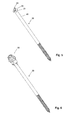
- eine Ansicht des erfindungsgemäßen Dämmstoffhalters mit partiell eingestecktem Spreizelement mit Übertragungskörper
- Figur 1b
- einen Längsschnitt A-A von
Figur 1 a - Figur 2
- eine perspektivische Teilschnittdarstellung nach
Figur 1 a - Figur 3
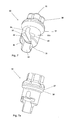
- eine perspektivische Ansicht des Übertragungskörpers in vergrößerter Form
- Figur 4
- eine Ansicht nach
Figur 3 - Figur 4a
- einen Längsschnitt B-B von
Figur 3 - Figur 4b
- einen Querschnitt C-C von
Figur 4 - Figur 4c
- ein Detail D von
Figur 4b - Figur 5
- ein Spreizelement mit an seinem Kopf angeformten Kamm
- Figur 6
- eine perspektivische Darstellung des Spreizelementes mit Übertragungskörper
- Figur 7
- eine perspektivische Darstellung des Übertragungskörpers in vergrößerter Form
- Figur 7a
- eine perspektivische Ansicht des Übertragungskörpers mit einer konischen Dichtfläche und einer Dichtwulst
- Figur 7b
- eine perspektivische Ansicht des Übertragungskörpers mit einer konischen Dichtfläche und einer Schneidringdichtfläche
- Figur 7c
- eine perspektivische Darstellung des Übertragungskörpers mit einem im Übertragungskörper und im Schaft angeordneten Rastelement
- Figur 8
- einen Querschnitt Detail G der aneinander liegenden Dichtflächen von Übertragungskörper und Aufnahmeteil
- Figur 9a
- einen Querschnitt des Aufnahmeteiles mit einer inneren konischen Dichtfläche und einer Dichtwulst
- Figur 9b
- einen Querschnitt des Aufnahmeteiles mit einer inneren konischen Dichtfläche und einer Schneidringfläche
- Der Dämmstoffhalter 1 gemäß
Fig. 1 a bis Fig. 9b ist mehrteilig ausgebildet und umfasst nachFig. 1 einen Dübel 10 mit einem Dübelschaft 11, ein in den Dübel 10 einführbares Spreizelement 20 und einen auf das Spreizelement 20 aufsteckbaren Übertragungskörper 30. Der Dübelschaft 11 weist einen in Längserstreckung X verlaufenden axialen Durchgang 12 durch den Dübel 10 auf. An dem einen Ende des Dübels 10 ist ein Spreizbereich S, der durch das eingeführte Spreizelement 20 aufspreizbar ist zwecks Verankerung des Dübels 10 in einem nicht dargestellten Untergrund, ausgebildet. An dem anderen Ende des Dübels 10 ist eine flanschartige Druckplatte 13 angeformt, die einen koaxial zur Längsachse X ausgebildeten Aufnahmeteil 14 aufweist, der zur Aufnahme des Übertragungskörpers 30 dient. Anstelle der Druckplatte 13 kann auch ein topfförmiger verbreiterter Kopf als Halteelement angeformt sein. Das Spreizelement 20 ist gemäßFig. 2 ,Fig. 5 und Fig. 6 nach Art einer Schraube mit einem scheibenförmigen bzw. tellerförmigen Kopf 21 und einem Schaft 22 ausgebildet. Auf der dem Schaft 22 abgewandten Seite des Kopfes 21 des Spreizelementes 20 ist nachFig. 5 ein axial vorstehender Kamm 23 angeformt. Der Kamm 23 ist durchgängig klingenförmig gestaltet. Hierbei bewirken die einander gegenüberliegenden Anlageflächen 24 des Kammes 23 einen vollflächigen Kontakt mit dem Übertragungskörper 30 zur Übertragung einer Drehbewegung bzw. eines Drehmomentes von dem Übertragungskörper 30 auf das Spreizelement 20. Der Spreizstift 20 ist aus Metall gefertigt und kann auch aus Kunststoff hergestellt sein. Des Weiteren weist der Übertragungskörper 30 einen Schaftteil 31 und einen einseitig offenen T-förmigen Einsteckbereich auf, der einen seitlichen Einsteckschlitz 32s und einen in den Übertragungskörper 30 übergehenden Aufnahmeraum 32 für den Kopf 21 und einen durch den Schaftteil 31 durchgängigen in axialer Richtung verlaufenden kanalartigen Längsschlitz 33 für das Spreizelement 20 enthält. Im Inneren des Aufnahmeraumes 32 ist ein quer zur Längsachse X des Übertragungskörpers 30 verlaufender Übertragungsbereich 34 ausgebildet (s.Fig. 1 a ,Fig. 1 b ,Fig. 7 ), d.h. der Aufnahmeraum 32 erweitert sich zu einem Übertragungsbereich 34. Dieser Übertragungsbereich 34 des Übertragungskörpers 30 dient der Aufnahme bzw. Versenkung des Kammes 23 zum Zwecke einer drehfesten kraft- und formschlüssigen Verbindung zwischen dem Übertragungskörper 30 und dem Spreizelement 20. GemäßFig. 1 a, Fig. 1 b ,Fig. 2 ist der Übertragungsbereich 34 im Inneren des Aufnahmeraumes 32 des Übertragungskörpers 30 tiefer als die Höhe des auf der dem Schaft 22 abgewandten Oberseite des Kopfes 21 des Spreizelementes 20 angeformten Kammes 23 ausgebildet, wodurch eine kammfreie abgerundete Zone O am geschlossenen Ende des Übertragungsbereiches 34 in Richtung der Längsachse X entsteht, die eine bessere Kräfteverteilung auf den Übertragungskörper 30 ermöglicht und ihn zusätzlich stabilisiert. NachFig. 4 bis Fig. 4c sind an der Innenseitenwand IW des Übertragungskörpers 30 und und/oder an der Innenseitenwand IS des Schaftteiles 31 zwei sich in axialer Richtung erstreckende Rastelemente 40 ausgebildet, die einen sicheren und festen Sitz des Spreizelementes 20 in dem Übertragungskörper 30 und in dem Schaftteil 31 gewährleisten. Vorzugsweise sind die Rastelemente 40 im Bereich des seitlichen Einsteckschlitzes 32 angeformt und werden begrenzt von der oberen und unteren Fläche F des Aufnahmeraumes 32. Ferner weist der Übertragungskörper 30 an seinem einen axialen Ende innere und/oder äußere Umfangs-Profilierungen 35, 36 für einen Werkzeugangriff auf zum Zwecke der Übertragung eines Drehmomentes bzw. einer Drehbewegung von dem Werkzeug auf den Übertragungskörper 30. Die inneren Umfangs-Profilierungen 35 sind als Innenangriff für ein Werkzeug, wie Innensechsrundschraubendreher und die äußeren Umfangs-Profilierungen 36 für einen Außenangriff als Sechskant- bzw. Sechsrund konstruiert (s.Fig. 1 b ,Fig. 3 ). Das Eindrehwerkzeug ist somit wahlweise manuell oder als elektrisch angetriebenes Werkzeug sowohl am Außenumfang als auch im Inneren des Übertragungskörpers 30 einsetzbar und steht mit dem Übertragungskörper 30 in einem festen Eingriff. Zur Verbesserung der Abdichtung sind der Übertragungskörper 30 und der Aufnahmeteil 14 im Wesentlichen kegelstumpfförmig ausgebildet. - In einer besonders bevorzugten Ausführungsform gemäß
Fig. 1a ,Fig. 3 weisen der Übertragungskörper 30 und der Aufnahmeteil 14 eine sich ergänzende konische Form auf, wobei an dem Übertragungskörper 30 oberhalb der kammfreien Zone O eine sich axial erstreckende konische Dichtfläche 37 und an dem Aufnahmeteil 14 eine innere konische Dichtfläche 141 ausgebildet ist. Durch die Konizität der Dichtflächen 37 / 141 wird beim Eindrehen des Spreizelementes 20 eine Erhöhung der Flächenpressung der beiden Dichtflächen 37 / 141 geschaffen. Die Dichtflächen 37 / 141 liegen im eingedrehten Zustand des Spreizelementes 20 formschlüssig aneinander an und ermöglichen eine hohe Dichtigkeit bzw. Abdichtung, so dass ein optimaler Schutz des Spreizelementes 20 gegen Witterungseinflüsse, wie Spritzwasser gegeben ist (s.Fig. 8 ). - Eine weitere Ausführungsform der Erfindung sieht nach
Fig. 7a vor, auf der konischen Dichtfläche 37 des Übertragungskörpers 30 zusätzlich eine radial verlaufende Dichtwulst 38 oder nachFig. 7b eine radial verlaufende Schneidringdichtfläche 39 auszubilden und auf der inneren konischen Dichtfläche 141 des Aufnahmeteiles 14 gemäßFig. 9a eine radial verlaufende Dichtwulst 142 oder gemäßFig. 9b eine radial verlaufende Schneidringdichtfläche 143 vorzusehen, die die Abdichtung zwischen dem Übertragungskörper 30 und dem Dübel 10 infolge der hohen Flächenpressung weiter verbessert und einen dauerhaften Schutz des Spreizelementes 20, beispielsweise gegenüber Feuchtigkeit ermöglicht. - In vorteilhafter Weise weisen die konische Dichtfläche 37 des Übertragungskörpers 30 und die innere konische Dichtfläche 141 des Aufnahmeteiles 14 einen identischen konischen Neigungswinkel α in Bezug auf die X-Achse auf, so dass beide Dichtflächen einen entsprechend großen Bereich abdecken bzw. einnehmen. Idealer Weise liegt der Neigungswinkel (α) zwischen 20° und 40°.
- Der Dübel 10 mit der Druckplatte 13 und dem Übertragungskörper 30 sind aus einem thermoplastischen Kunststoff, beispielsweise durch Spritzgießen hergestellt. Bevorzugt ist der Übertragungskörper 30 zwecks Aufnahme und Übertragung der Drehmomentkräfte aus einem witterungsbeständigen und schlagfesten/eindrehfesten verstärkten oder gefüllten Kunststoff gefertigt.
- Die Montage des erfindungsgemäßen mehrteiligen Dämmstoffhalters 1 erfolgt durch das seitliche Einstecken des Spreizelementes 20, beispielsweise einer Schraube 20 mit einem an der dem Schaft 22 abgewandten Seite des Kopfes 21 des Spreizelementes 20 angeformten axial vorstehenden Kamm 23 und einem auf den Schaft 22 des Spreizelementes 20 ausgebildeten Gewinde oder eines entsprechend ausgebildeten Bolzens in den Einsteckschlitz 32s des Übertragungskörpers 30. Hierbei wird der an dem scheibenförmigen Kopf 21 der Schraube bzw. des Bolzens 20 angeformte Kamm 23 in dem Übertragungsbereich 34 für eine drehfeste und zugfeste Verbindung aufgenommen. Durch Andrücken bzw. Hineindrücken der Schraube 20 in den Einsteckbereich 32s, 32, 33 verrastet der Kopf 21 und/oder Schaft 21 der Schraube 20 mit dem Rastelement 40 zu einer festen und drehsicheren Verbindung, so dass ein Herausfallen bzw. Lösen der Schraube 20 aus dem Übertragungskörper 30 verhindert wird. Die so miteinander verbundenen Teile 20, 30 werden partiell in den Dübel 10 eingesetzt. Der Übertragungskörper 30 wird mittels eines ausgewählten Eindrehwerkzeuges, beispielsweise am Außenumfang des Übertragungskörpers 30, in Umdrehungen versetzt, so dass sich der Spreizbereich S des Dübels 10 durch die Schraube aufweitet und der Dübel 10 fest im nicht dargestellten Untergrund verankert wird.
- Des Weiteren ist es möglich, anstelle einer Schraube mit Außengewinde z.B. einen Nagel, eine Nagelschraube oder einen Draht ohne Gewinde in den Übertragungskörper zum Einschlagen einzusetzen.
-
- 1 = Dämmstoffhalter
- 10 = Dübel
- 11 = Dübelschaft
- 12 = Durchgang
- 13 = Druckplatte
- 14 = Aufnahmeteil
- 141 = innere konische Dichtfläche von 14
- 142 = innere Dichtwulst
- 143 = innere Schneidringdichtfläche
- 20 = Spreizelement
- 21 = Kopf von 20
- 22 = Schaft von 20
- 23 = Kamm an 21
- 24 = Anlagefläche
- 30 = Übertragungskörper
- 31 = Schaftteil
- 32s = Einsteckschlitz
- 32 = Aufnahmeraum
- 33 = Längsschlitz
- 34 = Übertragungsbereich
- 35 = innere umfangsprofilierte Mitnahmeflächen
- 36 = äußere umfangsprofilierte Mltnahmeflächen
- 37 = konische Dichtfläche, axial
- 38 = Dichtwulst, radial
- 39 = Schneidringdichtfläche
- 40 = Rastelement
- S = Spreizbereich
- IW = Innenseitenwand von 30
- O = kammfreie Zone
- IS = Innenseitenwand von 31
- F = Flächen von 32
Claims (12)
- Dämmstoffhalter (1), umfassend einen Dübel (10) mit einem Dübelschaft (11), an dessen einem Ende ein Spreizbereich (S) ausgebildet ist und an dessen anderem Ende eine flanschartige Druckplatte (13) angeformt ist, wobei die flanschartige Druckplatte (13) einen koaxial zur Längsachse (X) ausgebildeten Aufnahmeteil (14) aufweist, und ein zur Aufweitung des Spreizbereiches (S) in den Dübel (10) einführbares Spreizelement (20) mit einem Kopf (21) und einem Schaft (22), und einen Übertragungskörper (30), an dem ein Schaftteil (31) ausgebildet ist, wobei der Übertragungskörper (30) einen seitlichen T-förmigen Einsteckbereich mit einem Einsteckschlitz (32s) und einem in den Übertragungskörper (30) übergehenden Aufnahmeraum (32) für den Kopf (21) und einem durch den Schaftteil (31) durchgängigen in axialer Richtung verlaufenden Längsschlitz (33) zum Einführen des Spreizelementes (20) enthält, dadurch gekennzeichnet, dass an der dem Schaft (22) abgewandten Seite des Kopfes (21) des Spreizelementes (20) ein axial vorstehender Kamm (23) angeformt ist, und dass im Inneren des Aufnahmeraumes (32) ein den Kamm (23) aufnehmender quer zur Längsachse X des Übertragungskörpers (30) verlaufender Übertragungsbereich (34) ausgebildet ist zum Zwecke einer drehfesten Verbindung zwischen dem Übertragungskörper (30) und dem Spreizelement (20).
- Dämmstoffhalter (1) nach Anspruch 1, dadurch gekennzeichnet, dass der im Inneren des Aufnahmeraumes (32) quer zur Längsachse X des Übertragungskörpers (30) verlaufende Übertragungsbereich (34) tiefer als die Höhe des axial vorstehenden Kammes (23) ausgebildet ist.
- Dämmstoffhalter (1) nach Anspruch 1 oder 2, dadurch gekennzeichnet, dass der Übertragungskörper (30) an seinem einen axialen Ende innere und/oder äußere Umfangs-Profilierungen (35, 36) für einen Werkzeugangriff aufweist.
- Dämmstoffhalter (1) nach einem der Ansprüche 1 bis 3, dadurch gekennzeichnet, dass der Übertragungskörper (30) und der Aufnahmeteil (14) im Wesentlichen kegelstumpfförmig ausgebildet sind.
- Dämmstoffhalter (1) nach einem der Ansprüche 1 bis 4, dadurch gekennzeichnet, dass der Übertragungskörper (30) oberhalb der kammfreien Zone (O) eine sich axial erstreckende konische Dichtfläche (37) aufweist, und dass an dem Aufnahmeteil (14) eine innere konische Dichtfläche (141) ausgebildet ist.
- Dämmstoffhalter (1) nach einem der Ansprüche 1 bis 5, dadurch gekennzeichnet, dass auf der konischen Dichtfläche (37) des Übertragungskörpers (30) eine radial verlaufende Dichtwulst (38) oder eine radial verlaufende Schneidringdichtfläche (39) ausgebildet ist.
- Dämmstoffhalter nach einem der Ansprüche 1 bis 5, dadurch gekennzeichnet, dass auf der inneren konischen Dichtfläche (141) des Aufnahmeteiles (14) eine radial verlaufende Dichtwulst (142) oder eine radial verlaufende Schneidringdichtfläche (143) vorgesehen ist.
- Dämmstoffhalter (1) nach einem der Ansprüche 1 bis 7, dadurch gekennzeichnet, dass der Übertragungskörper (30) mit seiner konischen Dichtfläche (37) an der inneren Dichtfläche (141) des Aufnahmeteiles formschlüssig anliegt.
- Dämmstoffhalter (1) nach einem der Ansprüche 1 bis 8, dadurch gekennzeichnet, dass die konische Dichtfläche (37) des Übertragungskörpers (30) und die innere konische Dichtfläche (141) des Aufnahmeteiles (14) einen identischen konischen Neigungswinkel (α) in Bezug auf die X-Achse aufweisen.
- Dämmstoffhalter (1) nach Anspruch 9, dadurch gekennzeichnet, dass der Neigungswinkel (α) zwischen 20° und 40° beträgt.
- Dämmstoffhalter (1) nach einem der Ansprüche 1 bis 10, dadurch gekennzeichnet, dass an der Innenseitenwand (IW) des Übertragungskörpers (30) im Bereich des Einsteckschlitzes (32) und/oder an der Innenseitenwand (IS) des Schaftteiles (31) mindestens ein nach innen vorstehendes sich in axialer Richtung erstreckendes Rastelement (40) ausgebildet ist, und dass das Rastelement (40) an der Innenseitenwand (IW) des Übertragungskörpers (30) von den inneren Flächen F des Aufnahmeraumes (32) begrenzt ist.
- Dämmstoffhalter (1) nach einem der Ansprüche 1 bis 11, dadurch gekennzeichnet, dass der Kopf (21) des Spreizelementes (20) scheibenförmig ausgebildet ist.
Applications Claiming Priority (1)
| Application Number | Priority Date | Filing Date | Title |
|---|---|---|---|
| DE200720014916 DE202007014916U1 (de) | 2007-10-26 | 2007-10-26 | Dämmstoffhalter |
Publications (2)
| Publication Number | Publication Date |
|---|---|
| EP2053179A1 true EP2053179A1 (de) | 2009-04-29 |
| EP2053179B1 EP2053179B1 (de) | 2015-04-15 |
Family
ID=39244791
Family Applications (1)
| Application Number | Title | Priority Date | Filing Date |
|---|---|---|---|
| EP20080018441 Not-in-force EP2053179B1 (de) | 2007-10-26 | 2008-10-22 | Dämmstofhalter |
Country Status (2)
| Country | Link |
|---|---|
| EP (1) | EP2053179B1 (de) |
| DE (1) | DE202007014916U1 (de) |
Cited By (2)
| Publication number | Priority date | Publication date | Assignee | Title |
|---|---|---|---|---|
| DE102013100968A1 (de) | 2013-01-31 | 2014-07-31 | Fischerwerke Gmbh & Co. Kg | Befestigungselement zur Befestigung einer Dämmstoffplatte an einem Untergrund |
| US8845967B2 (en) | 2008-12-22 | 2014-09-30 | Eppendorf Ag | Container and a device for indirectly cooling materials and method for producing the container |
Families Citing this family (1)
| Publication number | Priority date | Publication date | Assignee | Title |
|---|---|---|---|---|
| DE202007014916U1 (de) * | 2007-10-26 | 2008-03-27 | Kew Kunststofferzeugnisse Gmbh Wilthen | Dämmstoffhalter |
Citations (6)
| Publication number | Priority date | Publication date | Assignee | Title |
|---|---|---|---|---|
| EP0074469A1 (de) | 1981-09-16 | 1983-03-23 | EJOT Adolf Böhl GmbH & Co. KG | Befestigungselement für die Befestigung von wärme- und schallisolierenden Materialien |
| EP0765979A1 (de) | 1995-09-28 | 1997-04-02 | EJOT Kunststofftechnik GmbH & Co. KG | Befestigungselement für die Befestigung von wärmeisolierenden Materialien |
| DE19801548C1 (de) * | 1998-01-16 | 1999-06-24 | Ejot Kunststofftech Gmbh | Dübelsystem für wärmedämmende Verbundsysteme |
| DE20103427U1 (de) | 2001-02-28 | 2001-05-17 | KEW Kunststofferzeugnisse GmbH Wilthen, 02681 Wilthen | Dämmstoffhalter |
| DE202005002534U1 (de) | 2005-02-17 | 2006-06-29 | Fischerwerke Artur Fischer Gmbh & Co. Kg | Dämmstoffhalter |
| DE202007014916U1 (de) * | 2007-10-26 | 2008-03-27 | Kew Kunststofferzeugnisse Gmbh Wilthen | Dämmstoffhalter |
-
2007
- 2007-10-26 DE DE200720014916 patent/DE202007014916U1/de not_active Expired - Lifetime
-
2008
- 2008-10-22 EP EP20080018441 patent/EP2053179B1/de not_active Not-in-force
Patent Citations (8)
| Publication number | Priority date | Publication date | Assignee | Title |
|---|---|---|---|---|
| EP0074469A1 (de) | 1981-09-16 | 1983-03-23 | EJOT Adolf Böhl GmbH & Co. KG | Befestigungselement für die Befestigung von wärme- und schallisolierenden Materialien |
| EP0765979A1 (de) | 1995-09-28 | 1997-04-02 | EJOT Kunststofftechnik GmbH & Co. KG | Befestigungselement für die Befestigung von wärmeisolierenden Materialien |
| DE19801548C1 (de) * | 1998-01-16 | 1999-06-24 | Ejot Kunststofftech Gmbh | Dübelsystem für wärmedämmende Verbundsysteme |
| DE20103427U1 (de) | 2001-02-28 | 2001-05-17 | KEW Kunststofferzeugnisse GmbH Wilthen, 02681 Wilthen | Dämmstoffhalter |
| WO2002068832A1 (de) * | 2001-02-28 | 2002-09-06 | Kew Kunststofferzeugnisse Gmbh Wilthen | Dämmstoffhalter |
| EP1366303A1 (de) | 2001-02-28 | 2003-12-03 | Kew Kunststofferzeugnisse Gmbh Wilthen | Dämmstoffhalter |
| DE202005002534U1 (de) | 2005-02-17 | 2006-06-29 | Fischerwerke Artur Fischer Gmbh & Co. Kg | Dämmstoffhalter |
| DE202007014916U1 (de) * | 2007-10-26 | 2008-03-27 | Kew Kunststofferzeugnisse Gmbh Wilthen | Dämmstoffhalter |
Cited By (2)
| Publication number | Priority date | Publication date | Assignee | Title |
|---|---|---|---|---|
| US8845967B2 (en) | 2008-12-22 | 2014-09-30 | Eppendorf Ag | Container and a device for indirectly cooling materials and method for producing the container |
| DE102013100968A1 (de) | 2013-01-31 | 2014-07-31 | Fischerwerke Gmbh & Co. Kg | Befestigungselement zur Befestigung einer Dämmstoffplatte an einem Untergrund |
Also Published As
| Publication number | Publication date |
|---|---|
| DE202007014916U1 (de) | 2008-03-27 |
| EP2053179B1 (de) | 2015-04-15 |
Similar Documents
| Publication | Publication Date | Title |
|---|---|---|
| DE3045986C2 (de) | Befestigungselement für die Befestigung von wärmeisolierenden Platten | |
| DE19644507C2 (de) | Schraube und Verwendung einer Schraube zur Befestigung von Profilen auf einem Unterbau | |
| EP0955476B2 (de) | Befestigungsanordnung mit einer selbstschneidenden Schraube zum Einsatz in Beton. | |
| EP1050690B1 (de) | Befestigungsvorrichtung für plattenförmige Isolationselemente | |
| DE102012101320A1 (de) | Schraube und damit hergestellte Dünnblechverbindung | |
| DE8601106U1 (de) | Einstellbare Befestigungsvorrichtung zum Zusammenfügen von zwei Bauteilen | |
| EP1818477A2 (de) | Befestigungssystem für Bauteile an einem tragenden Untergrund sowie Verfahren und Montagehilfe zur Anbringung des Befestigungssystems | |
| DE4019157C1 (de) | ||
| EP0894202A1 (de) | Schraube zur befestigung von metall- und/oder kunststoffprofilen oder -platten auf einem unterbau | |
| EP2635818A1 (de) | Spreizdübel | |
| EP0846878B1 (de) | Dämmstoffhalter | |
| EP2053179B1 (de) | Dämmstofhalter | |
| DE10249993B4 (de) | Befestigungselement | |
| EP3045740B1 (de) | Befestigungselement zur Befestigung eines Bauteils an einem Wärmedämmverbundsystem | |
| DE202019001906U1 (de) | Einschraubdübel | |
| WO2014139946A1 (de) | Tülle und befestigungselement zum befestigen einer materialschicht | |
| DE19702838C2 (de) | Befestiger zur Fixierung von Platten an einer Unterkonstruktion | |
| DE19801548C1 (de) | Dübelsystem für wärmedämmende Verbundsysteme | |
| DE202012103721U1 (de) | Montageschraube zur Befestigung von Beschlagteilen, insbesondere von Bandteilen an Hohlkammerprofilen und einem Hohlkammerprofil | |
| EP0155484B1 (de) | Spreizdübel | |
| DE19808927C1 (de) | Befestigungselement für die Befestigung von wärmeisolierenden Platten an einer Unterkonstruktion mit Montagekontrolle | |
| EP3243993B1 (de) | Vorrichtung und verfahren zur befestigung eines baukörpers in einer von einer auflagefläche begrenzten öffnung | |
| DE102004005582A1 (de) | Dübelvorrichtung zur Verankerung von Wärmedämmplatten | |
| DE8606331U1 (de) | Befestigungseinrichtung für die dauerhafte Anordnung von Dichtungsbahnen und/oder Dämmplatten an der Blechtafel einer Flachdach-Abdeckplatte | |
| DE102015005691B4 (de) | Längenvariables Befestigungselement |
Legal Events
| Date | Code | Title | Description |
|---|---|---|---|
| PUAI | Public reference made under article 153(3) epc to a published international application that has entered the european phase |
Free format text: ORIGINAL CODE: 0009012 |
|
| AK | Designated contracting states |
Kind code of ref document: A1 Designated state(s): AT BE BG CH CY CZ DE DK EE ES FI FR GB GR HR HU IE IS IT LI LT LU LV MC MT NL NO PL PT RO SE SI SK TR |
|
| AX | Request for extension of the european patent |
Extension state: AL BA MK RS |
|
| 17P | Request for examination filed |
Effective date: 20091023 |
|
| 17Q | First examination report despatched |
Effective date: 20091117 |
|
| AKX | Designation fees paid |
Designated state(s): AT BE BG CH CY CZ DE DK EE ES FI FR GB GR HR HU IE IS IT LI LT LU LV MC MT NL NO PL PT RO SE SI SK TR |
|
| GRAP | Despatch of communication of intention to grant a patent |
Free format text: ORIGINAL CODE: EPIDOSNIGR1 |
|
| INTG | Intention to grant announced |
Effective date: 20141114 |
|
| GRAS | Grant fee paid |
Free format text: ORIGINAL CODE: EPIDOSNIGR3 |
|
| GRAA | (expected) grant |
Free format text: ORIGINAL CODE: 0009210 |
|
| AK | Designated contracting states |
Kind code of ref document: B1 Designated state(s): AT BE BG CH CY CZ DE DK EE ES FI FR GB GR HR HU IE IS IT LI LT LU LV MC MT NL NO PL PT RO SE SI SK TR |
|
| REG | Reference to a national code |
Ref country code: GB Ref legal event code: FG4D Free format text: NOT ENGLISH Ref country code: CH Ref legal event code: EP |
|
| REG | Reference to a national code |
Ref country code: IE Ref legal event code: FG4D Free format text: LANGUAGE OF EP DOCUMENT: GERMAN |
|
| REG | Reference to a national code |
Ref country code: AT Ref legal event code: REF Ref document number: 722086 Country of ref document: AT Kind code of ref document: T Effective date: 20150515 |
|
| REG | Reference to a national code |
Ref country code: DE Ref legal event code: R096 Ref document number: 502008012880 Country of ref document: DE Effective date: 20150528 |
|
| REG | Reference to a national code |
Ref country code: NL Ref legal event code: VDEP Effective date: 20150415 |
|
| REG | Reference to a national code |
Ref country code: LT Ref legal event code: MG4D |
|
| PG25 | Lapsed in a contracting state [announced via postgrant information from national office to epo] |
Ref country code: NL Free format text: LAPSE BECAUSE OF FAILURE TO SUBMIT A TRANSLATION OF THE DESCRIPTION OR TO PAY THE FEE WITHIN THE PRESCRIBED TIME-LIMIT Effective date: 20150415 |
|
| REG | Reference to a national code |
Ref country code: FR Ref legal event code: PLFP Year of fee payment: 8 |
|
| PG25 | Lapsed in a contracting state [announced via postgrant information from national office to epo] |
Ref country code: LT Free format text: LAPSE BECAUSE OF FAILURE TO SUBMIT A TRANSLATION OF THE DESCRIPTION OR TO PAY THE FEE WITHIN THE PRESCRIBED TIME-LIMIT Effective date: 20150415 Ref country code: HR Free format text: LAPSE BECAUSE OF FAILURE TO SUBMIT A TRANSLATION OF THE DESCRIPTION OR TO PAY THE FEE WITHIN THE PRESCRIBED TIME-LIMIT Effective date: 20150415 Ref country code: ES Free format text: LAPSE BECAUSE OF FAILURE TO SUBMIT A TRANSLATION OF THE DESCRIPTION OR TO PAY THE FEE WITHIN THE PRESCRIBED TIME-LIMIT Effective date: 20150415 Ref country code: NO Free format text: LAPSE BECAUSE OF FAILURE TO SUBMIT A TRANSLATION OF THE DESCRIPTION OR TO PAY THE FEE WITHIN THE PRESCRIBED TIME-LIMIT Effective date: 20150715 Ref country code: FI Free format text: LAPSE BECAUSE OF FAILURE TO SUBMIT A TRANSLATION OF THE DESCRIPTION OR TO PAY THE FEE WITHIN THE PRESCRIBED TIME-LIMIT Effective date: 20150415 Ref country code: PT Free format text: LAPSE BECAUSE OF FAILURE TO SUBMIT A TRANSLATION OF THE DESCRIPTION OR TO PAY THE FEE WITHIN THE PRESCRIBED TIME-LIMIT Effective date: 20150817 |
|
| PG25 | Lapsed in a contracting state [announced via postgrant information from national office to epo] |
Ref country code: GR Free format text: LAPSE BECAUSE OF FAILURE TO SUBMIT A TRANSLATION OF THE DESCRIPTION OR TO PAY THE FEE WITHIN THE PRESCRIBED TIME-LIMIT Effective date: 20150716 Ref country code: LV Free format text: LAPSE BECAUSE OF FAILURE TO SUBMIT A TRANSLATION OF THE DESCRIPTION OR TO PAY THE FEE WITHIN THE PRESCRIBED TIME-LIMIT Effective date: 20150415 Ref country code: IS Free format text: LAPSE BECAUSE OF FAILURE TO SUBMIT A TRANSLATION OF THE DESCRIPTION OR TO PAY THE FEE WITHIN THE PRESCRIBED TIME-LIMIT Effective date: 20150815 |
|
| REG | Reference to a national code |
Ref country code: DE Ref legal event code: R097 Ref document number: 502008012880 Country of ref document: DE |
|
| PG25 | Lapsed in a contracting state [announced via postgrant information from national office to epo] |
Ref country code: EE Free format text: LAPSE BECAUSE OF FAILURE TO SUBMIT A TRANSLATION OF THE DESCRIPTION OR TO PAY THE FEE WITHIN THE PRESCRIBED TIME-LIMIT Effective date: 20150415 Ref country code: DK Free format text: LAPSE BECAUSE OF FAILURE TO SUBMIT A TRANSLATION OF THE DESCRIPTION OR TO PAY THE FEE WITHIN THE PRESCRIBED TIME-LIMIT Effective date: 20150415 |
|
| PLBE | No opposition filed within time limit |
Free format text: ORIGINAL CODE: 0009261 |
|
| STAA | Information on the status of an ep patent application or granted ep patent |
Free format text: STATUS: NO OPPOSITION FILED WITHIN TIME LIMIT |
|
| PG25 | Lapsed in a contracting state [announced via postgrant information from national office to epo] |
Ref country code: SK Free format text: LAPSE BECAUSE OF FAILURE TO SUBMIT A TRANSLATION OF THE DESCRIPTION OR TO PAY THE FEE WITHIN THE PRESCRIBED TIME-LIMIT Effective date: 20150415 Ref country code: RO Free format text: LAPSE BECAUSE OF NON-PAYMENT OF DUE FEES Effective date: 20150415 Ref country code: PL Free format text: LAPSE BECAUSE OF FAILURE TO SUBMIT A TRANSLATION OF THE DESCRIPTION OR TO PAY THE FEE WITHIN THE PRESCRIBED TIME-LIMIT Effective date: 20150415 |
|
| 26N | No opposition filed |
Effective date: 20160118 |
|
| PG25 | Lapsed in a contracting state [announced via postgrant information from national office to epo] |
Ref country code: SI Free format text: LAPSE BECAUSE OF FAILURE TO SUBMIT A TRANSLATION OF THE DESCRIPTION OR TO PAY THE FEE WITHIN THE PRESCRIBED TIME-LIMIT Effective date: 20150415 Ref country code: LU Free format text: LAPSE BECAUSE OF FAILURE TO SUBMIT A TRANSLATION OF THE DESCRIPTION OR TO PAY THE FEE WITHIN THE PRESCRIBED TIME-LIMIT Effective date: 20151022 |
|
| REG | Reference to a national code |
Ref country code: CH Ref legal event code: PL |
|
| GBPC | Gb: european patent ceased through non-payment of renewal fee |
Effective date: 20151022 |
|
| PG25 | Lapsed in a contracting state [announced via postgrant information from national office to epo] |
Ref country code: MC Free format text: LAPSE BECAUSE OF FAILURE TO SUBMIT A TRANSLATION OF THE DESCRIPTION OR TO PAY THE FEE WITHIN THE PRESCRIBED TIME-LIMIT Effective date: 20150415 |
|
| REG | Reference to a national code |
Ref country code: IE Ref legal event code: MM4A |
|
| PG25 | Lapsed in a contracting state [announced via postgrant information from national office to epo] |
Ref country code: LI Free format text: LAPSE BECAUSE OF NON-PAYMENT OF DUE FEES Effective date: 20151031 Ref country code: CH Free format text: LAPSE BECAUSE OF NON-PAYMENT OF DUE FEES Effective date: 20151031 Ref country code: GB Free format text: LAPSE BECAUSE OF NON-PAYMENT OF DUE FEES Effective date: 20151022 |
|
| REG | Reference to a national code |
Ref country code: FR Ref legal event code: PLFP Year of fee payment: 9 |
|
| PG25 | Lapsed in a contracting state [announced via postgrant information from national office to epo] |
Ref country code: IE Free format text: LAPSE BECAUSE OF NON-PAYMENT OF DUE FEES Effective date: 20151022 |
|
| PG25 | Lapsed in a contracting state [announced via postgrant information from national office to epo] |
Ref country code: HU Free format text: LAPSE BECAUSE OF FAILURE TO SUBMIT A TRANSLATION OF THE DESCRIPTION OR TO PAY THE FEE WITHIN THE PRESCRIBED TIME-LIMIT; INVALID AB INITIO Effective date: 20081022 Ref country code: BG Free format text: LAPSE BECAUSE OF FAILURE TO SUBMIT A TRANSLATION OF THE DESCRIPTION OR TO PAY THE FEE WITHIN THE PRESCRIBED TIME-LIMIT Effective date: 20150415 |
|
| PG25 | Lapsed in a contracting state [announced via postgrant information from national office to epo] |
Ref country code: SE Free format text: LAPSE BECAUSE OF FAILURE TO SUBMIT A TRANSLATION OF THE DESCRIPTION OR TO PAY THE FEE WITHIN THE PRESCRIBED TIME-LIMIT Effective date: 20150415 Ref country code: CY Free format text: LAPSE BECAUSE OF FAILURE TO SUBMIT A TRANSLATION OF THE DESCRIPTION OR TO PAY THE FEE WITHIN THE PRESCRIBED TIME-LIMIT Effective date: 20150415 |
|
| PG25 | Lapsed in a contracting state [announced via postgrant information from national office to epo] |
Ref country code: BE Free format text: LAPSE BECAUSE OF NON-PAYMENT OF DUE FEES Effective date: 20151031 |
|
| PG25 | Lapsed in a contracting state [announced via postgrant information from national office to epo] |
Ref country code: TR Free format text: LAPSE BECAUSE OF FAILURE TO SUBMIT A TRANSLATION OF THE DESCRIPTION OR TO PAY THE FEE WITHIN THE PRESCRIBED TIME-LIMIT Effective date: 20150415 Ref country code: MT Free format text: LAPSE BECAUSE OF FAILURE TO SUBMIT A TRANSLATION OF THE DESCRIPTION OR TO PAY THE FEE WITHIN THE PRESCRIBED TIME-LIMIT Effective date: 20150415 |
|
| REG | Reference to a national code |
Ref country code: FR Ref legal event code: PLFP Year of fee payment: 10 |
|
| PGFP | Annual fee paid to national office [announced via postgrant information from national office to epo] |
Ref country code: DE Payment date: 20171023 Year of fee payment: 10 Ref country code: CZ Payment date: 20171013 Year of fee payment: 10 Ref country code: FR Payment date: 20171023 Year of fee payment: 10 |
|
| PGFP | Annual fee paid to national office [announced via postgrant information from national office to epo] |
Ref country code: IT Payment date: 20171020 Year of fee payment: 10 Ref country code: AT Payment date: 20171018 Year of fee payment: 10 |
|
| REG | Reference to a national code |
Ref country code: DE Ref legal event code: R119 Ref document number: 502008012880 Country of ref document: DE |
|
| REG | Reference to a national code |
Ref country code: AT Ref legal event code: MM01 Ref document number: 722086 Country of ref document: AT Kind code of ref document: T Effective date: 20181022 |
|
| PG25 | Lapsed in a contracting state [announced via postgrant information from national office to epo] |
Ref country code: DE Free format text: LAPSE BECAUSE OF NON-PAYMENT OF DUE FEES Effective date: 20190501 Ref country code: CZ Free format text: LAPSE BECAUSE OF NON-PAYMENT OF DUE FEES Effective date: 20181022 |
|
| PG25 | Lapsed in a contracting state [announced via postgrant information from national office to epo] |
Ref country code: FR Free format text: LAPSE BECAUSE OF NON-PAYMENT OF DUE FEES Effective date: 20181031 |
|
| PG25 | Lapsed in a contracting state [announced via postgrant information from national office to epo] |
Ref country code: AT Free format text: LAPSE BECAUSE OF NON-PAYMENT OF DUE FEES Effective date: 20181022 Ref country code: IT Free format text: LAPSE BECAUSE OF NON-PAYMENT OF DUE FEES Effective date: 20181022 |