EP2052956A2 - Saddle - Google Patents
Saddle Download PDFInfo
- Publication number
- EP2052956A2 EP2052956A2 EP08157666A EP08157666A EP2052956A2 EP 2052956 A2 EP2052956 A2 EP 2052956A2 EP 08157666 A EP08157666 A EP 08157666A EP 08157666 A EP08157666 A EP 08157666A EP 2052956 A2 EP2052956 A2 EP 2052956A2
- Authority
- EP
- European Patent Office
- Prior art keywords
- pad
- base
- saddle
- hole
- fastening
- Prior art date
- Legal status (The legal status is an assumption and is not a legal conclusion. Google has not performed a legal analysis and makes no representation as to the accuracy of the status listed.)
- Withdrawn
Links
Images


Classifications
-
- B—PERFORMING OPERATIONS; TRANSPORTING
- B62—LAND VEHICLES FOR TRAVELLING OTHERWISE THAN ON RAILS
- B62J—CYCLE SADDLES OR SEATS; AUXILIARY DEVICES OR ACCESSORIES SPECIALLY ADAPTED TO CYCLES AND NOT OTHERWISE PROVIDED FOR, e.g. ARTICLE CARRIERS OR CYCLE PROTECTORS
- B62J1/00—Saddles or other seats for cycles; Arrangement thereof; Component parts
- B62J1/18—Covers for saddles or other seats; Paddings
- B62J1/22—Covers with built-in paddings
-
- B—PERFORMING OPERATIONS; TRANSPORTING
- B62—LAND VEHICLES FOR TRAVELLING OTHERWISE THAN ON RAILS
- B62J—CYCLE SADDLES OR SEATS; AUXILIARY DEVICES OR ACCESSORIES SPECIALLY ADAPTED TO CYCLES AND NOT OTHERWISE PROVIDED FOR, e.g. ARTICLE CARRIERS OR CYCLE PROTECTORS
- B62J1/00—Saddles or other seats for cycles; Arrangement thereof; Component parts
- B62J1/002—Saddles having a seating area with a central cavity or depression
Definitions
- the present invention provides a saddle for a vehicle, in particular a saddle with great comfort for a bicycle.
- a pad made of foam is typically provided on a base that is made of a hard material.
- the pad is generally too soft, so even though it can slightly decrease the stress incurred when the rider sits on the saddle, the buttocks or crotches of the cyclist will still feel uncomfortable due to the pressing action of the hard base.
- some pads made of soft materials fail to deform in response to the different shapes of buttocks and crotches, and even may be gathered in areas where high stress is expected.
- some racing bicycles or road bicycles adopt pads integrally formed from a hard material, which makes the cyclists feel more uncomfortable. Therefore, the material of the saddle has become an important factor that dominates the riding comfort of the saddle.
- One objective of this invention is to provide a saddle with an appropriate deformation and cushioning capabilities to allow the cyclist to sit thereon in comfort.
- the saddle of this invention comprises a base, a pad and a fastening device adapted to connect the base with the pad.
- the saddle of this invention is characterized in that the pad is made of a material comprising ethylene-vinyl acetate (EVA).
- EVA ethylene-vinyl acetate
- This invention provides a saddle, which primarily comprises a base, a pad, a fastening device, a vent device and a rail device.
- the pad is made of a material comprising ethylene-vinyl acetate (EVA). This particular material provides the pad with appropriate deformation and cushioning capabilities as well as an appropriate supporting capability.
- EVA material should be foamed to produce the pad 33 to further improve the deformation and cushioning capabilities of the pad 33 . It should be noted that the material of the pad may also be a composite formed by the EVA and other materials.
- FIGS. 1A to 1J depict a saddle 1 of the first embodiment of this invention.
- the saddle 1 of this embodiment comprises a base 31 , a pad 33 , a fastening device 35 , a vent device 37 and a rail device 39 .
- the base 31 may be made of a material including a variety of plastics, carbon fibers or the like.
- the pad 33 is primarily made of the EVA, and may also be made of a composite formed by the EVA and other materials.
- the fastening device 35 is adapted to be fixedly connected the base 31 and the pad 33 .
- the fastening device 35 comprises three fastening pins 351 , three fastening caps 353 , three first through-holes 357 and three second through-holes 359 .
- the first through-holes 357 are dispersedly formed in the base 31 .
- the second through-holes 359 are formed in the pad 33 at locations corresponding to the first through-holes 357 respectively.
- Each of the fastening pins 351 are inserted through both the first through-hole 357 and the corresponding second through-hole 359 to be interlocked with the corresponding fastening cap 353 to fix the pad 33 onto the base 31 .
- each of the fastening pins 351 comprises a neck portion 351a , a cap portion 351b and a snap fit head 351c .
- Each of the fastening cap 353 comprises a cap portion 353a and a snap fit hole 353b .
- the pad 33 has three grooves 331 on the top surface so the second through-holes 359 in the pad 33 are formed in the corresponding grooves 331 respectively.
- each of the grooves 331 has a depth greater than (in other embodiments, may also be equal to) a cap height of each of the fastening pin 351 to prevent the fastening device 35 from protruding beyond the pad 33 .
- the fastening pin 351 may also be inserted through the first through-hole 357 and the second through-hole 359 from a reverse direction to clamp the base 31 and the pad 33 together.
- the base portion of the cap portion 351b of the fastening pin 351 abuts against the bottom surface of the base 31
- the base portion of the fastening cap 353 abuts against the top surface of the pad 33 .
- each of the grooves 331 has a depth greater than or equal to a cap height of each of the fastening cap 353 .
- the number of the fastening pins 351 , the fastening caps 353 , the first through-holes 357 , the second through-holes 359 and the grooves 331 is not merely limited to three, but may also be another number. It should be noted that when the number of these elements is different from that of this embodiment, the same objectives can also be accomplished simply by correspondingly designing the relative locations. Therefore, such equivalent modifications shall also fall within the scope of the claims of this invention,
- the vent device 37 comprises a first vent 371 and a second vent 373 .
- the first vent 371 is formed on the base 31 and extends from the top surface to the bottom surface of the base 31 to guide air from the bottom surface of the base 31 to the pad 33 .
- the second vent 373 is formed on the pad 33 corresponding to the first vent 371 and extends from the top surface to the bottom surface of the pad 33 to guide air from the bottom surface of the base 31 to the top surface of the pad 33 .
- the vent device 37 may also be eliminated or formed with additional vents in other embodiments to match the requirements in terms of weight, air permeability or the like.
- the rail device 39 is located on the bottom surface of the base 31 , with which the saddle can be fixedly connected to a bicycle frame via elements, such as seat posts and seat post clamps.
- the rail device 39 is preferably made of a material selected from a group consisting of magnesium, magnesium alloy, titanium, titanium alloy, nickel and nickel alloy to provide adequate support for the base 31 while still cater for the tendency towards lightweight bicycle parts.
- a saddle 2 of the second embodiment is similar to the saddle 1 of the first embodiment except that the fastening device 35 ' fixes the base 31 and the pad 33 together by a different means.
- the fastening device 35 ' also comprises three first through-holes 357 and three second through-holes 359 .
- the three fastening pins 351 and the three fastening caps 353 used in the first embodiment are replaced by three cowl fasteners 355 , i.e., each of the cowl fasteners 355 is adapted to provide functions similar to a fastening pin 351 in combination with a fastening cap 353 .
- the first through-holes 357 are also dispersedly formed in the base 31
- the second through-holes 359 are also formed in the pad 33 at locations corresponding to the first through-holes 357 respectively.
- the fastening device 35' simply uses the cowl fasteners 355 inserted through both a first through-hole 357 and a corresponding second through-hole 359 respectively to fix the pad 33 onto the base 31 .
- each of the cowl fasteners 355 comprises a neck portion 355a , a cap portion 355b and a discontinuous conical portion 355c .
- a base portion of the cap portion 355b of the cowl fastener 355 abuts against a top surface of the pad 33
- a support portion of the discontinuous conical portion 355c of the cowl fastener 355 abuts against the bottom surface of the base 31 .
- the neck portion 355a of the cowl fastener 355 is inserted through the first through-hole 357 and the second through-hole 359 .
- the base 31 and the pad 33 are adapted to be clamped by the cap portion 355b and the discontinuous conical portion 355c of the cowl fastener 355 .
- the pad 33 has three grooves 331 on the top surface, so the second through-holes 359 in the pad 33 are formed in the corresponding grooves 331 respectively.
- each of the grooves 331 has a depth greater than (in other embodiments, may also be equal to) a cap height of each of the cowl fasteners 355 to prevent the fastening device 35 from protruding beyond the pad 33 .
- the cowl fasteners 355 of this embodiment may also be inserted through the first through-hole 357 and the second through-hole 359 from the reverse direction.
- the base portion of the cap portion 355b of the cowl fastener 355 abuts against the bottom surface of the base 31
- the support portion of the discontinuous conical portion 355c of the cowl fastener 355 abuts against the top surface of the pad 33 .
- each of the grooves 331 has a depth greater than or equal to a discontinuous conical height of each of the cowl fasteners 355 .
- the number of the cowl fastener 355 , the first through-holes 357 , the second through-holes 359 and the grooves 331 is not merely limited to three, but may also be another number. It should be noted that when the number of these elements is different from that of this embodiment, the same objectives can also be accomplished simply by correspondingly designing the relative locations. Therefore, such equivalent modifications shall also fall within the scope of the claims of this invention. Other parts of this embodiment are similar in structure and material to those of the first embodiment, and thus will not be further described again herein.
- the third embodiment of this invention is a saddle 3 , which is depicted in FIGS. 3A to 3C .
- the saddle 3 of this embodiment is similar to the saddle 2 of the second embodiment.
- the base 31 , the pad 33 , the vent device 37 , the rail device 39 and other parts of the saddle 3 are all the same as those of the saddle 2 of the second embodiment.
- the third embodiment is different from the second embodiment in that six cowl fasteners 355 are provided in the third embodiment.
- the pad 33 of the third embodiment also has six recesses 333 instead of three grooves on the top surface to accommodate the cap portions 355b or the discontinuous conical portions 355c of the cowl fasteners 355 .
- the base 31 comprises six first through-holes 357
- the pad 33 comprises six second through-holes 359 formed in the six recesses 333 respectively.
- each of the recesses 333 has a depth greater than (in other embodiments, may also be equal to) the cap height of each of the cowl fasteners 355 .
- each of the cowl fasteners 355 of this embodiment is inserted through the first through-hole 357 and the second through-hole 359 from the positive direction.
- each of the cowl fasteners 355 of this embodiment may also be inserted through the first through-hole 357 and the second through-hole 359 from the reverse direction, in which case, each of the recesses 331 has a depth greater than or equal to the discontinuous conical height of each of the cowl fasteners 355 .
- the fastening device of this invention may also be in the form of various different fastening means such as threading, riveting, gluing, inserting or other means.
- any fastening means that is able to fix the EVA pad of this invention to the base can be applied to this invention.
- the fastening means described in the first, the second or the third embodiments or even threading means are used in the saddle of this invention to fix the pad to the base, the pad can be detachably fixed to the base.
- the pad may be detached from the base and replaced. This results in a greatly improved applicability and industrial competitiveness of the pad of this invention.
- the application of the saddle of this invention is not merely limited to bicycles, and the same concepts may also be applied to motorcycles, automobiles or other transportation vehicles.
- the pad of the saddle of this invention is made of a material comprising the EVA, which is deformable in response to the different stress distribution to conform to the figure of the cyclist.
- the pad will experience an appropriate deformation under the action of the weight of the cyclist to conform to the shapes of the buttocks and crotches of the cyclist.
- this material can also absorb vibrations arising during the riding process, and provide an improved cushioning and supporting capabilities, thus remarkably improving comfort of the riding process.
Abstract
Description
- This application claims priority to Taiwan Patent Application No.
097112838 filed on April 9, 2008 US Provisional Application No. 60/982,942 filed on October 26, 2007 - Not applicable.
- The present invention provides a saddle for a vehicle, in particular a saddle with great comfort for a bicycle.
- In modem society, people are more and more concerned about recreation and body building. Among various sports, bicycle riding not only has a benefit on fitness, but also helps to relax the mind. Acco rdingly, as bicycles have become more of a means for recreation and physical exercise rather than merely a transportation tool. As a result, the demands on the bicycle requirements have increased accordingly as well.
- When riding a bicycle, the weight of a cyclist is primarily supported by the buttocks. Because of the weight, the area of the buttocks that come into contact with the saddle are put under an extremely high stress. Therefore, if no provisions for alleviating the stress are made on the saddle, the cyclist is less willing to ride the bicycle. Hence, the comfort of the saddle has become an important factor with which people are concerned when making a purchase decision.
- When a cyclist rides a bicycle on various road conditions, vibrations arising during the riding process often make the cyclist feels uncomfortable, and this makes it difficult for the cyclist to ride the bicycle in comfort for an extended time. Furthermore, for a commercially available bicycle saddle, a pad made of foam is typically provided on a base that is made of a hard material. However, the pad is generally too soft, so even though it can slightly decrease the stress incurred when the rider sits on the saddle, the buttocks or crotches of the cyclist will still feel uncomfortable due to the pressing action of the hard base. Moreover, some pads made of soft materials fail to deform in response to the different shapes of buttocks and crotches, and even may be gathered in areas where high stress is expected. Furthermore, some racing bicycles or road bicycles adopt pads integrally formed from a hard material, which makes the cyclists feel more uncomfortable. Therefore, the material of the saddle has become an important factor that dominates the riding comfort of the saddle.
- In view of this, it is highly desirable in the art to provide a saddle with appropriate deformation and cushioning capabilities.
- One objective of this invention is to provide a saddle with an appropriate deformation and cushioning capabilities to allow the cyclist to sit thereon in comfort.
- The saddle of this invention comprises a base, a pad and a fastening device adapted to connect the base with the pad. The saddle of this invention is characterized in that the pad is made of a material comprising ethylene-vinyl acetate (EVA). As a result, the saddle of this invention is able to appropriately deform in response to the buttocks and crotches of different cyclists and absorb vibrations arising during the riding process. This remarkably improves the comfort of the saddle of this invention.
- The detailed technology and preferred embodiments implemented for the subject invention are described in the following paragraphs accompanying the appended drawings for people skilled in this field to well appreciate the features of the claimed invention.
-
-
FIG 1A is a front view of the first embodiment of this invention; -
FIG 1B is a rear view of the first embodiment of this invention; -
FIG 1C is a side view of the first embodiment of this invention; -
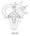
FIG. 1D is a top view of the first embodiment of this invention; -
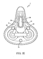
FIG 1E is a bottom view of the first embodiment of this invention; -
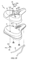
FIG. 1F is an exploded view of the first embodiment of this invention; -
FIG 1G is an exploded view from another viewing angle of the first embodiment of this invention; -
FIG 1H is a schematic assembled view of the first embodiment of this invention; -
FIG 1I is a partially cross-sectional exploded view of the first embodiment of this invention; -
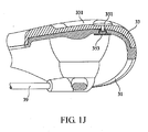
FIG 1J is a partially cross-sectional assembled view of the first embodiment of this invention; -
FIG 2A is a top view of the second embodiment of this invention; -
FIG 2B is a partially cross-sectional exploded view of the second embodiment of this invention; -
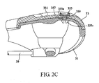
FIG. 2C is a partially cross-sectional assembled view of the second embodiment of this invention; -
FIG. 3A is a top view of the third embodiment of this invention; -
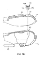
FIG. 3B is a partially cross-sectional exploded view of the third embodiment of this invention; and -
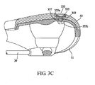
FIG 3C is a partially cross-sectional assembled view of the third embodiment of this invention. - This invention provides a saddle, which primarily comprises a base, a pad, a fastening device, a vent device and a rail device. The pad is made of a material comprising ethylene-vinyl acetate (EVA). This particular material provides the pad with appropriate deformation and cushioning capabilities as well as an appropriate supporting capability. The EVA material should be foamed to produce the
pad 33 to further improve the deformation and cushioning capabilities of thepad 33. It should be noted that the material of the pad may also be a composite formed by the EVA and other materials. -
FIGS. 1A to 1J depict asaddle 1 of the first embodiment of this invention. Thesaddle 1 of this embodiment comprises abase 31, apad 33, afastening device 35, avent device 37 and arail device 39. Thebase 31 may be made of a material including a variety of plastics, carbon fibers or the like. As previously described, thepad 33 is primarily made of the EVA, and may also be made of a composite formed by the EVA and other materials. - In this embodiment, the
fastening device 35 is adapted to be fixedly connected thebase 31 and thepad 33. Thefastening device 35 comprises threefastening pins 351, threefastening caps 353, three first through-holes 357 and three second through-holes 359. As depicted inFIGS. 1F to 1J , the first through-holes 357 are dispersedly formed in thebase 31. The second through-holes 359 are formed in thepad 33 at locations corresponding to the first through-holes 357 respectively. Each of the fastening pins 351 are inserted through both the first through-hole 357 and the corresponding second through-hole 359 to be interlocked with thecorresponding fastening cap 353 to fix thepad 33 onto thebase 31. - As depicted in
FIGS. 1F ,1G ,1I and1J , each of the fastening pins 351 comprises aneck portion 351a, acap portion 351b and a snapfit head 351c. Each of thefastening cap 353 comprises acap portion 353a and a snapfit hole 353b. When the snapfit head 351c of thefastening pin 351 are engaged into the snapfit hole 353b of thefastening cap 353 to fix thepad 33 onto thebase 31, a base portion of thecap portion 351b of thefastening pin 351 abuts against a top surface of thepad 33, a base portion of thecap portion 353a of the fastening caps 353 abuts against a bottom surface of thebase 31, and theneck portion 351a of thefastening pin 351 is inserted through the first through-hole 357 and the second through-hole 359. In other words, thebase 31 and thepad 33 are adapted to be clamped by thecap portion 351b of thefastening pin 351 and thecap portion 353a of thefastening cap 353. - To improve the air permeability of the
saddle 1 and prevent thefastening device 35 from protruding beyond thepad 33, thepad 33 has threegrooves 331 on the top surface so the second through-holes 359 in thepad 33 are formed in thecorresponding grooves 331 respectively. In this embodiment, each of thegrooves 331 has a depth greater than (in other embodiments, may also be equal to) a cap height of each of thefastening pin 351 to prevent thefastening device 35 from protruding beyond thepad 33. - In other examples, the
fastening pin 351 may also be inserted through the first through-hole 357 and the second through-hole 359 from a reverse direction to clamp thebase 31 and thepad 33 together. In this case, the base portion of thecap portion 351b of thefastening pin 351 abuts against the bottom surface of thebase 31, and the base portion of thefastening cap 353 abuts against the top surface of thepad 33. Also, each of thegrooves 331 has a depth greater than or equal to a cap height of each of thefastening cap 353. Furthermore, the number of the fastening pins 351, the fastening caps 353, the first through-holes 357, the second through-holes 359 and thegrooves 331 is not merely limited to three, but may also be another number. It should be noted that when the number of these elements is different from that of this embodiment, the same objectives can also be accomplished simply by correspondingly designing the relative locations. Therefore, such equivalent modifications shall also fall within the scope of the claims of this invention, - The
vent device 37 comprises afirst vent 371 and asecond vent 373. Thefirst vent 371 is formed on thebase 31 and extends from the top surface to the bottom surface of the base 31 to guide air from the bottom surface of the base 31 to thepad 33. Thesecond vent 373 is formed on thepad 33 corresponding to thefirst vent 371 and extends from the top surface to the bottom surface of thepad 33 to guide air from the bottom surface of the base 31 to the top surface of thepad 33. With such an arrangement, a cyclist can sit on thesaddle 1 and ride the bicycle in comfort without the feeling stuffy. It should be noted that although thevent device 37 is used in this embodiment, the vent device may also be eliminated or formed with additional vents in other embodiments to match the requirements in terms of weight, air permeability or the like. - The
rail device 39 is located on the bottom surface of thebase 31, with which the saddle can be fixedly connected to a bicycle frame via elements, such as seat posts and seat post clamps. Therail device 39 is preferably made of a material selected from a group consisting of magnesium, magnesium alloy, titanium, titanium alloy, nickel and nickel alloy to provide adequate support for the base 31 while still cater for the tendency towards lightweight bicycle parts. - As shown in
FIGS. 2A to 2C , the second embodiment of this invention is depicted therein. Asaddle 2 of the second embodiment is similar to thesaddle 1 of the first embodiment except that the fastening device 35' fixes thebase 31 and thepad 33 together by a different means. In this embodiment, the fastening device 35' also comprises three first through-holes 357 and three second through-holes 359. However, the threefastening pins 351 and the threefastening caps 353 used in the first embodiment are replaced by threecowl fasteners 355, i.e., each of thecowl fasteners 355 is adapted to provide functions similar to afastening pin 351 in combination with afastening cap 353. - As shown in
FIG 2A , in the fastening device 35' of this embodiment, the first through-holes 357 are also dispersedly formed in thebase 31, and the second through-holes 359 are also formed in thepad 33 at locations corresponding to the first through-holes 357 respectively. The fastening device 35' simply uses thecowl fasteners 355 inserted through both a first through-hole 357 and a corresponding second through-hole 359 respectively to fix thepad 33 onto thebase 31. - As depicted in
FIGS. 2B and2C , each of thecowl fasteners 355 comprises aneck portion 355a, acap portion 355b and a discontinuousconical portion 355c. When thecowl fastener 355 fixes thepad 33 onto thebase 31, a base portion of thecap portion 355b of thecowl fastener 355 abuts against a top surface of thepad 33, while a support portion of the discontinuousconical portion 355c of thecowl fastener 355 abuts against the bottom surface of thebase 31. Similarly, theneck portion 355a of thecowl fastener 355 is inserted through the first through-hole 357 and the second through-hole 359. In other words, thebase 31 and thepad 33 are adapted to be clamped by thecap portion 355b and the discontinuousconical portion 355c of thecowl fastener 355. - In this embodiment, the
pad 33 has threegrooves 331 on the top surface, so the second through-holes 359 in thepad 33 are formed in thecorresponding grooves 331 respectively. In this embodiment, each of thegrooves 331 has a depth greater than (in other embodiments, may also be equal to) a cap height of each of thecowl fasteners 355 to prevent thefastening device 35 from protruding beyond thepad 33. - In other examples, the
cowl fasteners 355 of this embodiment may also be inserted through the first through-hole 357 and the second through-hole 359 from the reverse direction. In this case, the base portion of thecap portion 355b of thecowl fastener 355 abuts against the bottom surface of thebase 31, while the support portion of the discontinuousconical portion 355c of thecowl fastener 355 abuts against the top surface of thepad 33. Also, each of thegrooves 331 has a depth greater than or equal to a discontinuous conical height of each of thecowl fasteners 355. Furthermore, the number of thecowl fastener 355, the first through-holes 357, the second through-holes 359 and thegrooves 331 is not merely limited to three, but may also be another number. It should be noted that when the number of these elements is different from that of this embodiment, the same objectives can also be accomplished simply by correspondingly designing the relative locations. Therefore, such equivalent modifications shall also fall within the scope of the claims of this invention. Other parts of this embodiment are similar in structure and material to those of the first embodiment, and thus will not be further described again herein. - The third embodiment of this invention is a
saddle 3, which is depicted inFIGS. 3A to 3C . Thesaddle 3 of this embodiment is similar to thesaddle 2 of the second embodiment. In more detail, thebase 31, thepad 33, thevent device 37, therail device 39 and other parts of thesaddle 3 are all the same as those of thesaddle 2 of the second embodiment. However, the third embodiment is different from the second embodiment in that sixcowl fasteners 355 are provided in the third embodiment. Thepad 33 of the third embodiment also has sixrecesses 333 instead of three grooves on the top surface to accommodate thecap portions 355b or the discontinuousconical portions 355c of thecowl fasteners 355. - Accordingly, the
base 31 comprises six first through-holes 357, while thepad 33 comprises six second through-holes 359 formed in the sixrecesses 333 respectively. In this embodiment, each of therecesses 333 has a depth greater than (in other embodiments, may also be equal to) the cap height of each of thecowl fasteners 355. Similar to the second embodiment, each of thecowl fasteners 355 of this embodiment is inserted through the first through-hole 357 and the second through-hole 359 from the positive direction. However, in other examples, each of thecowl fasteners 355 of this embodiment may also be inserted through the first through-hole 357 and the second through-hole 359 from the reverse direction, in which case, each of therecesses 331 has a depth greater than or equal to the discontinuous conical height of each of thecowl fasteners 355. - In other examples, the fastening device of this invention may also be in the form of various different fastening means such as threading, riveting, gluing, inserting or other means. In other words, any fastening means that is able to fix the EVA pad of this invention to the base can be applied to this invention. If the fastening means described in the first, the second or the third embodiments or even threading means are used in the saddle of this invention to fix the pad to the base, the pad can be detachably fixed to the base. Hence, when a dirty or worn pad needs to be replaced, or a pad of a different size or style is desired, or other situations requiring replacement of a pad arise, the pad may be detached from the base and replaced. This results in a greatly improved applicability and industrial competitiveness of the pad of this invention. Furthermore, the application of the saddle of this invention is not merely limited to bicycles, and the same concepts may also be applied to motorcycles, automobiles or other transportation vehicles.
- The pad of the saddle of this invention is made of a material comprising the EVA, which is deformable in response to the different stress distribution to conform to the figure of the cyclist. When the cyclist sits on the saddle of this invention, the pad will experience an appropriate deformation under the action of the weight of the cyclist to conform to the shapes of the buttocks and crotches of the cyclist. On the other hand, this material can also absorb vibrations arising during the riding process, and provide an improved cushioning and supporting capabilities, thus remarkably improving comfort of the riding process.
- The above disclosure is related to the detailed technical contents and inventive features thereof. People skilled in this field may proceed with a variety of modifications and replacements based on the disclosures and suggestions of the invention as described without departing from the characteristics thereof. Nevertheless, although such modifications and replacements are not fully disclosed in the above descriptions, they have substantially been covered in the following claims as appended.
Claims (17)
- A saddle, comprising: a base; a pad being made of a material comprising Ethylene-vinyl acetate (EVA); and a fastening device being adapted to connect the base with the pad.
- The saddle as claimed in claim 1, wherein the fastening device comprises at least one first through hole, at least one second through hole, at least one fastening pin and at least one fastening cap, the at least one first through hole is formed in the base, the at least one second through hole is formed in the pad, and the at least one fastening pin is inserted through the at least one first through hole and the at least one second through hole to interlock with the fastening cap to fix the pad onto the base.
- The saddle as claimed in claim 2, wherein the fastening pin comprises a neck portion, a cap portion and a snap fit head, the fastening cap comprises a snap fit hole, when the snap fit head of the fastening pin interlocks with the snap fit hole of the fastening cap to fix the pad onto the base, wherein a base portion of the cap portion abuts against a top surface of the pad and a base portion of the fastening cap abuts against a bottom surface of the base or the base portion of the cap portion abuts against the bottom surface of the base and the base portion of the fastening cap abuts against the top surface of the pad, and the neck portion is inserted through the first through hole and the second through hole.
- The saddle as claimed in claim 1, wherein the fastening device comprises at least one first through hole, at least one second through hole and at least one cowl fastener, the at least one first through hole is formed in the base, the at least one second through hole is formed in the pad, and the at least one cowl fastener is inserted through the at least one first through hole and the at least one second through hole to clamp the base with the pad.
- The saddle as claimed in claim 4, wherein the at least one cowl fastener comprises a neck portion, a cap portion and a discontinuous conical portion, when the base and the pad are clamped by the at least one cowl fastener, wherein a base portion of the cap portion abuts against a top surface of the pad and a support portion of the discontinuous conical portion abuts against a bottom surface of the base or the base portion of the cap portion abuts against the bottom surface of the base and the support portion of the discontinuous conical portion abuts against the top surface of the pad, and the neck portion is inserted through the at least one first through hole and the at least one second through hole.
- The saddle as claimed in claim 2, wherein a top surface of the pad further comprises at least one groove, the at least one second through hole is formed in the at least one groove, a depth of the at least one groove is greater than or equal to a cap height of the fastening pin or of the fastening cap.
- The saddle as claimed in claim 4, wherein a top surface of the pad further comprises at least one groove, the at least one second through hole is formed in the at least one groove, a depth of the at least one groove is greater than or equal to a cap height of the cowl fastener or a discontinuous conical height of the cowl fastener.
- The saddle as claimed in claim 2, wherein the fastening device comprises three first through holes three second through holes, three fastening pins and three fastening caps, the first through holes are formed in the base, the second through holes are formed in the pad, and the fastening pins are inserted through the first through holes and the second through holes respectively to interlock with the fastening caps to fix the pad on the base.
- The saddle as claimed in claim 4, wherein the fastening device comprises three first through holes, three second through holes, and three cowl fasteners, the first through holes are formed in the base, the second through holes are formed in the pad, and the cowl fasteners are inserted through the first through holes and the second through holes respectively to clamp the base with the pad.
- The saddle as claimed in any of the claims 8 or 9, wherein the top surface of the pad comprises three grooves.
- The saddle as claimed in claim 4, wherein the top surface of the pad further comprises at least one recess, the at least one second through hole is formed in the at least one recess, a depth of the at least one recess is greater than or equal to a cap height or a discontinuous conical height of the cowl fastener.
- The saddle as claimed in claim 1, wherein the base comprises at least a first vent, extending from the top surface to the bottom surface of the base to guide air to flow from bottom surface to the pad.
- The saddle as claimed in claim 12, wherein the pad comprises at least a second vent corresponding to the first vent, extending from a top surface to a bottom surface of the pad to guide the air to flow from the bottom surface of the base to the top surface of the pad.
- The saddle as claimed in claim 1, further comprising a rail device, disposed at a bottom surface of the base.
- The saddle as claimed in claim 14, wherein the rail device is made of a material selected from the group consisting of magnesium, magnesium alloy, titanium, titanium alloy, nickel and nickel alloy thereof.
- The saddle as claimed in claim 1, wherein the pad is made of the material comprising EVA foam material.
- The saddle as claimed in claim 1, wherein the fastening device is adapted to connect the base with the pad detachably.
Applications Claiming Priority (2)
| Application Number | Priority Date | Filing Date | Title |
|---|---|---|---|
| US98294207P | 2007-10-26 | 2007-10-26 | |
| TW97112838A TWI376326B (en) | 2007-10-26 | 2008-04-09 | Saddle |
Publications (2)
| Publication Number | Publication Date |
|---|---|
| EP2052956A2 true EP2052956A2 (en) | 2009-04-29 |
| EP2052956A3 EP2052956A3 (en) | 2010-05-26 |
Family
ID=40293880
Family Applications (1)
| Application Number | Title | Priority Date | Filing Date |
|---|---|---|---|
| EP08157666A Withdrawn EP2052956A3 (en) | 2007-10-26 | 2008-06-05 | Saddle |
Country Status (2)
| Country | Link |
|---|---|
| US (1) | US7669924B2 (en) |
| EP (1) | EP2052956A3 (en) |
Cited By (3)
| Publication number | Priority date | Publication date | Assignee | Title |
|---|---|---|---|---|
| EP2085302A3 (en) * | 2008-01-30 | 2009-12-23 | International Bicycle Products Corporation | Saddle assembly and venting device thereof |
| ITUB20153651A1 (en) * | 2015-09-15 | 2017-03-15 | Maclart S R L | SADDLE FOR CYCLES |
| DE202018003121U1 (en) * | 2018-07-05 | 2019-10-09 | Ergon Lnternational Gmbh | bicycle saddle |
Families Citing this family (5)
| Publication number | Priority date | Publication date | Assignee | Title |
|---|---|---|---|---|
| ITVI20070134A1 (en) * | 2007-05-09 | 2008-11-10 | Selle Royal Spa | SESSION STRUCTURE AND METHOD FOR ITS REALIZATION. |
| KR101149395B1 (en) * | 2008-10-20 | 2012-06-01 | 손범용 | Rest For The Saddle OF Bicycle |
| ITVR20110052A1 (en) * | 2011-03-11 | 2012-09-12 | Selle Royal Spa | SUPPORTING ELEMENT FOR THE HUMAN BODY |
| TWI577592B (en) * | 2015-10-21 | 2017-04-11 | Bicycle cushions | |
| WO2018225098A1 (en) * | 2017-03-14 | 2018-12-13 | Maclart S.R.L. | Saddle for cycles |
Citations (6)
| Publication number | Priority date | Publication date | Assignee | Title |
|---|---|---|---|---|
| US594316A (en) * | 1897-11-23 | David basch | ||
| GB115841A (en) * | 1917-05-15 | 1919-02-06 | Aloysius Petrus Van Leuven | Bicycle Saddle. |
| US3997214A (en) * | 1972-02-09 | 1976-12-14 | The Jacobs Corporation | Bicycle seat |
| EP0728660A1 (en) * | 1995-02-22 | 1996-08-28 | SELLE SAN MARCO DI GIRARDI COMM. LUIGI S.p.A. | A bicycle sadlle and a method for its manufacture |
| US20040195871A1 (en) * | 2003-04-02 | 2004-10-07 | Cionlli Industrial Co., Ltd. | Method for making a bicycle seat and product made thereby |
| US20070246978A1 (en) * | 2006-04-24 | 2007-10-25 | Tsai-Yun Yu | Ventilative cycle saddle |
Family Cites Families (7)
| Publication number | Priority date | Publication date | Assignee | Title |
|---|---|---|---|---|
| US1900574A (en) * | 1931-07-15 | 1933-03-07 | Scovill Manufacturing Co | Fastening device for inherently resilient articles |
| US3388946A (en) * | 1966-09-08 | 1968-06-18 | Ronald R. Grace | Motorcycle seat |
| US4103966A (en) * | 1977-09-19 | 1978-08-01 | Huffy Corporation | Saddle construction |
| US5356205A (en) | 1992-09-18 | 1994-10-18 | Inmotion, Inc. | Seat assembly with a defined flexure region, venting or support nodules |
| US5918931A (en) * | 1997-02-24 | 1999-07-06 | Culbertson; Russell D. | Bicycle saddle |
| US6523891B1 (en) * | 2001-07-11 | 2003-02-25 | Paul M. Yates | Multi-shell bicycle saddle |
| ITVI20050240A1 (en) | 2005-09-13 | 2007-03-14 | Selle Royal Spa | CUSTOMIZABLE SEAT STRUCTURE FOR HUMAN BODY, PARTICULARLY FOR PEDAL VEHICLES |
-
2008
- 2008-06-03 US US12/132,292 patent/US7669924B2/en not_active Expired - Fee Related
- 2008-06-05 EP EP08157666A patent/EP2052956A3/en not_active Withdrawn
Patent Citations (6)
| Publication number | Priority date | Publication date | Assignee | Title |
|---|---|---|---|---|
| US594316A (en) * | 1897-11-23 | David basch | ||
| GB115841A (en) * | 1917-05-15 | 1919-02-06 | Aloysius Petrus Van Leuven | Bicycle Saddle. |
| US3997214A (en) * | 1972-02-09 | 1976-12-14 | The Jacobs Corporation | Bicycle seat |
| EP0728660A1 (en) * | 1995-02-22 | 1996-08-28 | SELLE SAN MARCO DI GIRARDI COMM. LUIGI S.p.A. | A bicycle sadlle and a method for its manufacture |
| US20040195871A1 (en) * | 2003-04-02 | 2004-10-07 | Cionlli Industrial Co., Ltd. | Method for making a bicycle seat and product made thereby |
| US20070246978A1 (en) * | 2006-04-24 | 2007-10-25 | Tsai-Yun Yu | Ventilative cycle saddle |
Cited By (3)
| Publication number | Priority date | Publication date | Assignee | Title |
|---|---|---|---|---|
| EP2085302A3 (en) * | 2008-01-30 | 2009-12-23 | International Bicycle Products Corporation | Saddle assembly and venting device thereof |
| ITUB20153651A1 (en) * | 2015-09-15 | 2017-03-15 | Maclart S R L | SADDLE FOR CYCLES |
| DE202018003121U1 (en) * | 2018-07-05 | 2019-10-09 | Ergon Lnternational Gmbh | bicycle saddle |
Also Published As
| Publication number | Publication date |
|---|---|
| US20090108644A1 (en) | 2009-04-30 |
| US7669924B2 (en) | 2010-03-02 |
| EP2052956A3 (en) | 2010-05-26 |
Similar Documents
| Publication | Publication Date | Title |
|---|---|---|
| US7669924B2 (en) | Saddle | |
| US20090108643A1 (en) | Detachable Saddle and Pad-Replaceable Saddle Set | |
| EP2085302B1 (en) | Saddle assembly and venting device thereof | |
| US6402236B1 (en) | Split rail bicycle saddle | |
| TWI596029B (en) | Ventilated saddle for bicycles, motorcycles and/or other pedal driven machines | |
| EP2689993B1 (en) | Bicycle saddle | |
| US9016779B2 (en) | Bicycle or ride on vehicle seats and saddles | |
| JP7197578B2 (en) | motorcycle seat arrangement | |
| KR20110030915A (en) | Saddle assembly for bicycle | |
| US20110018315A1 (en) | Bicycle saddle | |
| US7328944B2 (en) | Contour motorcycle seat | |
| EP1394025A1 (en) | Saddle for vehicles, in particular for racing bikes, mountain bikes, city bikes and the like | |
| EP1667896B1 (en) | Viscoelastic support structure with improved energy absorption properties | |
| TW200918396A (en) | Saddle | |
| US20080134647A1 (en) | Riding saddle and its method of manufacture | |
| US20060208542A1 (en) | Motorcycle seat | |
| US20090212608A1 (en) | Bicycle seat system | |
| JPH06344964A (en) | Riding-saddle type seat for vehicle | |
| AU2012262657B2 (en) | Improvements to bicycle or ride on vehicle seats and saddles | |
| US9932080B2 (en) | Straddle-type vehicle | |
| KR102210249B1 (en) | Supplementary back for motorcycle | |
| JP5460563B2 (en) | Seat for saddle-ride type vehicle | |
| US20060197307A1 (en) | Supports and support systems for wheeled vehicles | |
| EP1531118B1 (en) | Bicycle saddle | |
| US20170101146A1 (en) | Motorcycle Control Pads |
Legal Events
| Date | Code | Title | Description |
|---|---|---|---|
| PUAI | Public reference made under article 153(3) epc to a published international application that has entered the european phase |
Free format text: ORIGINAL CODE: 0009012 |
|
| AK | Designated contracting states |
Kind code of ref document: A2 Designated state(s): AT BE BG CH CY CZ DE DK EE ES FI FR GB GR HR HU IE IS IT LI LT LU LV MC MT NL NO PL PT RO SE SI SK TR |
|
| AX | Request for extension of the european patent |
Extension state: AL BA MK RS |
|
| PUAL | Search report despatched |
Free format text: ORIGINAL CODE: 0009013 |
|
| AK | Designated contracting states |
Kind code of ref document: A3 Designated state(s): AT BE BG CH CY CZ DE DK EE ES FI FR GB GR HR HU IE IS IT LI LT LU LV MC MT NL NO PL PT RO SE SI SK TR |
|
| AX | Request for extension of the european patent |
Extension state: AL BA MK RS |
|
| RIC1 | Information provided on ipc code assigned before grant |
Ipc: B62J 1/20 20060101ALI20100419BHEP Ipc: B62J 1/00 20060101AFI20090210BHEP |
|
| AKY | No designation fees paid | ||
| STAA | Information on the status of an ep patent application or granted ep patent |
Free format text: STATUS: THE APPLICATION IS DEEMED TO BE WITHDRAWN |
|
| 18D | Application deemed to be withdrawn |
Effective date: 20101129 |
|
| REG | Reference to a national code |
Ref country code: DE Ref legal event code: R108 Effective date: 20110419 |