EP2051511A2 - Terminal mobile de réception de diffusion - Google Patents
Terminal mobile de réception de diffusion Download PDFInfo
- Publication number
- EP2051511A2 EP2051511A2 EP08018258A EP08018258A EP2051511A2 EP 2051511 A2 EP2051511 A2 EP 2051511A2 EP 08018258 A EP08018258 A EP 08018258A EP 08018258 A EP08018258 A EP 08018258A EP 2051511 A2 EP2051511 A2 EP 2051511A2
- Authority
- EP
- European Patent Office
- Prior art keywords
- broadcast
- channel
- user
- channels
- broadcast channel
- Prior art date
- Legal status (The legal status is an assumption and is not a legal conclusion. Google has not performed a legal analysis and makes no representation as to the accuracy of the status listed.)
- Granted
Links
Images


Classifications
-
- H—ELECTRICITY
- H04—ELECTRIC COMMUNICATION TECHNIQUE
- H04N—PICTORIAL COMMUNICATION, e.g. TELEVISION
- H04N5/00—Details of television systems
- H04N5/44—Receiver circuitry for the reception of television signals according to analogue transmission standards
-
- H—ELECTRICITY
- H04—ELECTRIC COMMUNICATION TECHNIQUE
- H04N—PICTORIAL COMMUNICATION, e.g. TELEVISION
- H04N5/00—Details of television systems
- H04N5/44—Receiver circuitry for the reception of television signals according to analogue transmission standards
- H04N5/50—Tuning indicators; Automatic tuning control
-
- H—ELECTRICITY
- H04—ELECTRIC COMMUNICATION TECHNIQUE
- H04B—TRANSMISSION
- H04B1/00—Details of transmission systems, not covered by a single one of groups H04B3/00 - H04B13/00; Details of transmission systems not characterised by the medium used for transmission
- H04B1/38—Transceivers, i.e. devices in which transmitter and receiver form a structural unit and in which at least one part is used for functions of transmitting and receiving
- H04B1/40—Circuits
-
- H—ELECTRICITY
- H04—ELECTRIC COMMUNICATION TECHNIQUE
- H04N—PICTORIAL COMMUNICATION, e.g. TELEVISION
- H04N21/00—Selective content distribution, e.g. interactive television or video on demand [VOD]
- H04N21/40—Client devices specifically adapted for the reception of or interaction with content, e.g. set-top-box [STB]; Operations thereof
- H04N21/41—Structure of client; Structure of client peripherals
- H04N21/414—Specialised client platforms, e.g. receiver in car or embedded in a mobile appliance
- H04N21/41407—Specialised client platforms, e.g. receiver in car or embedded in a mobile appliance embedded in a portable device, e.g. video client on a mobile phone, PDA, laptop
-
- H—ELECTRICITY
- H04—ELECTRIC COMMUNICATION TECHNIQUE
- H04N—PICTORIAL COMMUNICATION, e.g. TELEVISION
- H04N21/00—Selective content distribution, e.g. interactive television or video on demand [VOD]
- H04N21/40—Client devices specifically adapted for the reception of or interaction with content, e.g. set-top-box [STB]; Operations thereof
- H04N21/43—Processing of content or additional data, e.g. demultiplexing additional data from a digital video stream; Elementary client operations, e.g. monitoring of home network or synchronising decoder's clock; Client middleware
- H04N21/433—Content storage operation, e.g. storage operation in response to a pause request, caching operations
- H04N21/4331—Caching operations, e.g. of an advertisement for later insertion during playback
-
- H—ELECTRICITY
- H04—ELECTRIC COMMUNICATION TECHNIQUE
- H04N—PICTORIAL COMMUNICATION, e.g. TELEVISION
- H04N21/00—Selective content distribution, e.g. interactive television or video on demand [VOD]
- H04N21/40—Client devices specifically adapted for the reception of or interaction with content, e.g. set-top-box [STB]; Operations thereof
- H04N21/43—Processing of content or additional data, e.g. demultiplexing additional data from a digital video stream; Elementary client operations, e.g. monitoring of home network or synchronising decoder's clock; Client middleware
- H04N21/438—Interfacing the downstream path of the transmission network originating from a server, e.g. retrieving MPEG packets from an IP network
- H04N21/4383—Accessing a communication channel
- H04N21/4384—Accessing a communication channel involving operations to reduce the access time, e.g. fast-tuning for reducing channel switching latency
Definitions
- the present invention relates to a mobile terminal and corresponding method for receiving a digital multimedia broadcast.
- Analog broadcasting which is currently being used, was originally developed for reception by a fixed terminal. Accordingly, when a user receives audio broadcast signals while walking or driving a vehicle, the sound quality of the audio broadcast signals are significantly lowered. Therefore, a higher level output and a wider frequency band are required.
- digital audio broadcasting technologies are now being used in place of the related art analog broadcasting.
- Examples of such digital audio broadcasting technologies include the Digital Audio Broadcasting (DAB) system in Europe (where Eureka-147 has been adopted as the DAB standard), the Digital Audio Radio (DAR) system in the United States, the Digital Radio Broadcasting (DRB) system in Canada, the Digital Sound Broadcasting (DSB) system in the International Telecommunication Union (ITU-R), and the Digital Multimedia Broadcasting (DMB) system in Korea.
- DAB Digital Audio Broadcasting
- DAR Digital Audio Radio
- DAR Digital Radio Broadcasting
- DVB Digital Radio Broadcasting
- DVB Digital Sound Broadcasting
- ITU-R International Telecommunication Union
- DMB Digital Multimedia Broadcasting
- signals carrying audio data with CD level quality can be received in a moving vehicle.
- the concept of audio or radio broadcasting has been expanded to include visual data.
- multimedia data such as news reports, weather and traffic information, geographic and location information, video information, and the like, can be transmitted via broadcast signals.
- digital broadcasting generally provides a better sound quality than existing AM and FM radio broadcasts, and also provides various data services (including text, graphics, video, etc.) at a data transmission rate of about 1.5 Mbits/sec.
- the digital broadcasting systems also support bi-directional services that allow user interactions. Therefore, broadcasting terminals such as a broadcasting mobile terminal can now receive broadcast programs, sporting events, etc. and the user is able to view such broadcast programs while on the move. However, there is often a delay in a broadcast program when the user changes channels, views other information, etc.
- one object of the present invention is to address the above-noted and other objects.
- Another object of the present invention is to provide a mobile terminal and corresponding method for reducing a broadcasting time delay time when the user changes a channel.
- the present invention provides in one aspect a mobile terminal including an input unit configured to enter a broadcast mode so as to display a broadcast program on a first broadcast channel, a buffering unit configured to buffer a broadcast program on a second broadcast channel different than the first broadcast channel, and a display unit configured to display the buffered broadcast program on the second broadcast channel when a channel change command is entered on the input unit for changing the first broadcast channel to the second broadcast channel.
- the present invention provides a method of controlling a mobile terminal, and which includes entering a broadcast mode so as to display a broadcast program on a first broadcast channel, buffering a broadcast program on a second broadcast channel different than the first broadcast channel, and displaying the buffered broadcast program on the second broadcast channel when a channel change command is entered for changing the first broadcast channel to the second broadcast channel.
- FIG. 1 is a block diagram illustrating a mobile terminal according to an embodiment of the present invention
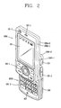
- FIG. 2 is a front perspective view of a mobile terminal according to an embodiment of the present invention.
- FIG. 3 is a rear perspective view of the mobile terminal illustrated in FIG. 2 ;
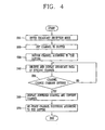
- FIG. 4 is a flowchart illustrating a method of changing channels in a mobile terminal according to an embodiment of the present invention
- FIG. 5 is an overview illustrating a channel buffering or switching setup screen in a mobile terminal according to an embodiment of the present invention
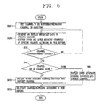
- FIG. 6 is a flowchart illustrating a method of changing broadcast channels based on user preferences according to an embodiment of the present invention
- FIG. 7 is a flowchart illustrating a method of changing broadcast channels in a mobile terminal according to another embodiment of the present invention.
- FIG. 8 is a view illustrating a screen of a mobile terminal according to an embodiment of the present invention.
- FIG. 9 is a flowchart illustrating a method of changing broadcast channels in a mobile terminal according to still another embodiment of the present invention.
- FIG. 1 is a block diagram of a mobile terminal 100 according to an embodiment of the present invention.
- the mobile terminal 100 includes a wireless communication unit 110 having one or more components which permits wireless communication between the mobile terminal 100 and a wireless communication system or network within which the mobile terminal is located.
- the wireless communication unit 110 includes a broadcast receiving module 111 that receives a broadcast signal and/or broadcast associated information from an external broadcast managing entity via a broadcast channel.
- the broadcast channel may include a satellite channel and a terrestrial channel.
- broadcast managing entity generally refers to a system which transmits a broadcast signal and/or broadcast associated information.
- broadcast associated information include information associated with a broadcast channel, a broadcast program, a broadcast service provider, etc.
- broadcast associated information may include an electronic program guide (EPG) of digital multimedia broadcasting (DMB) and electronic service guide (ESG) of digital video broadcast-handheld (DVB-H).
- EPG electronic program guide
- ESG electronic service guide
- the broadcast signal may be implemented as a TV broadcast signal, a radio broadcast signal, and a data broadcast signal, among others.
- the broadcast signal may further include a broadcast signal combined with a TV or radio broadcast signal.
- the broadcast receiving module 111 is also configured to receive broadcast signals transmitted from various types of broadcast systems.
- broadcasting systems include the digital multimedia broadcasting-terrestrial (DMB-T) system, the digital multimedia broadcasting-satellite (DMB-S) system, the digital video broadcast-handheld (DVB-H) system, the data broadcasting system known as media forward link only (MediaFLO®) and the integrated services digital broadcast-terrestrial (ISDB-T) system among others.
- DMB-T digital multimedia broadcasting-terrestrial
- DMB-S digital multimedia broadcasting-satellite
- DVD-H digital video broadcast-handheld
- MediaFLO® media forward link only
- ISDB-T integrated services digital broadcast-terrestrial
- Receiving multicast signals is also possible.
- data received by the broadcast receiving module 111 may be stored in a suitable device, such as a memory 160.
- the wireless communication unit 110 also includes a mobile communication module 112 that transmits/receives wireless signals to/from one or more network entities (e.g., base station, Node-B). Such signals may represent audio, video, multimedia, control signaling, and data, among others.
- network entities e.g., base station, Node-B.
- the wireless Internet module 113 that supports Internet access for the mobile terminal.
- the module 113 may be internally or externally coupled to the terminal.
- the wireless communication unit 110 also includes a short-range communication module 114 that facilitates relatively short-range communications. Suitable technologies for implementing this module include radio frequency identification (RFID), infrared data association (IrDA), ultra-wideband (UWB), as well at the networking technologies commonly referred to as Bluetooth and ZigBee, to name a few.
- RFID radio frequency identification
- IrDA infrared data association
- UWB ultra-wideband
- a position-location module 115 is also included in the wireless communication unit 110 and identifies or otherwise obtains the location of the mobile terminal 100.
- the position-location module 115 may be implemented using global positioning system (GPS) components which cooperate with associated satellites, network components, and combinations thereof.
- GPS global positioning system
- the mobile terminal 100 also includes an Audio/video (A/V) input unit 120 that provides audio or video signals to the mobile terminal 100.
- A/V Audio/video
- the AN input unit 120 includes a camera 121 and a microphone 122.
- the camera 121 receives and processes image frames of still pictures or video.
- the microphone 122 receives an external audio signal while the portable device is in a particular mode, such as a phone call mode, recording mode and voice recognition mode. The received audio signal is then processed and converted into digital data.
- the portable device, and in particular, the AN input unit 120 typically includes assorted noise removing algorithms to remove noise generated in the course of receiving the external audio signal.
- data generated by the AN input unit 120 may be stored in the memory 160, utilized by an output unit 150, or transmitted via one or more modules of the communication unit 110. If desired, two or more microphones and/or cameras may be used.
- the mobile terminal 100 also includes a user input unit 130 that generates input data responsive to user manipulation of an associated input device or devices.
- a user input unit 130 that generates input data responsive to user manipulation of an associated input device or devices. Examples of such devices include a keypad, a dome switch, a touchpad (e.g., static pressure/capacitance), a jog wheel and a jog switch.
- a specific example is one in which the user input unit 130 is configured as a touchpad in cooperation with a touch screen display, which will be described in more detail below.
- touch sensitive technologies may be used.
- the direction of the user's finger(s), a stylus, or other object(s) placed in direct contact with the screen can be performed.
- proximity detection may be used, whereby the user's finger(s) or object is detected when place near the screen without having to contact with the screen itself.
- the touch pad (or other touch sensitive membrane) may be combined onto the display 151 to thus form a touch screen, which allows for both user inputs via touching and provides visual outputs.
- a sensing unit 140 is also included in the mobile terminal 100 and provides status measurements of various aspects of the mobile terminal 100.
- the sensing unit 140 may detect an open/close status of the mobile terminal 100, relative positioning of components (e.g., a display and keypad) of the mobile terminal 100, a change of position of the mobile terminal 100 or a component of the mobile terminal 100, a presence or absence of user contact with the mobile terminal 100, orientation or acceleration/deceleration of the mobile terminal 100, etc.
- the sensing unit 140 may sense whether a sliding portion of the mobile terminal 100 is open or closed.
- Other examples include the sensing unit 140 sensing the presence or absence of power provided by a power supply 190, the presence or absence of a coupling or other connection between an interface unit 170 and an external device, etc.
- the interface unit 170 is often implemented to couple the mobile terminal 100 with external devices.
- Typical external devices include wired/wireless headphones, external chargers, power supplies, storage devices configured to store data (e.g., audio, video, pictures, etc.), earphones, and microphones, among others.
- the interface unit 170 may be configured using a wired/wireless data port, a card socket (e.g., for coupling to a memory card, a subscriber identity module (SIM) card, a user identity module (UIM) card, a removable user identity module (RUIM) card, etc.), audio input/output ports and video input/output ports.
- SIM subscriber identity module
- UIM user identity module
- RUIM removable user identity module
- the output unit 150 generally includes various components which support the output requirements of the mobile terminal 100.
- the mobile terminal 100 also includes a display 151 that visually displays information associated with the mobile terminal 100. For instance, if the mobile terminal 100 is operating in a phone call mode, the display 151 will generally provide a user interface or graphical user interface which includes information associated with placing, conducting, and terminating a phone call. As another example, if the mobile terminal 100 is in a video call mode or a photographing mode, the display 151 may additionally or alternatively display images which are associated with these modes.
- the display 151 also preferably includes a touch screen working in cooperation with an input device, such as a touchpad. This configuration permits the display 151 to function both as an output device and an input device.
- the display 151 may be implemented using display technologies including, for example, a liquid crystal display (LCD), a thin film transistor-liquid crystal display (TFT-LCD), an organic light-emitting diode display (OLED), a flexible display and a three-dimensional display.
- the display 151 also provides a user interface (UI) or graphic user interface (GUI).
- UI user interface
- GUI graphic user interface
- the mobile terminal 100 may also include one or more of such displays.
- An example of a two-display embodiment is one in which one display is configured as an internal display (viewable when the terminal is in an opened position) and a second display configured as an external display (viewable in both the open and closed positions).
- FIG. 1 further shows the output unit 150 having an audio output module 152 which supports the audio output requirements of the mobile terminal 100.
- the audio output module 152 is often implemented using one or more speakers, buzzers, other audio producing devices, and combinations thereof.
- the audio output module 152 functions in various modes including a call-receiving mode, a call-placing mode, a recording mode, a voice recognition mode and a broadcast reception mode. During operation, the audio output module 152 outputs audio relating to a particular function (e.g., call received, message received, and errors).
- the output unit 150 is further shown having an alarm 153, which is used to signal or otherwise identify the occurrence of a particular event associated with the mobile terminal 100.
- Typical events include a call received, a message received and user input received.
- An example of such output includes the providing of tactile sensations (e.g., vibration) to a user.
- the alarm 153 may be configured to vibrate responsive to the mobile terminal 100 receiving a call or message.
- a vibration is provided by the alarm 153 responsive to receiving user input at the mobile terminal 100, thus providing a tactile feedback mechanism.
- the various outputs provided by the components of the output unit 150 may be separately performed, or such output may be performed using any combination of such components.
- the memory 160 is generally used to store various types of data to support the processing, control, and storage requirements of the mobile terminal 100. Examples of such data include program instructions for applications operating on the mobile terminal 100, call history, contact data, phonebook data, messages, pictures, video, etc.
- RAM random access memory
- SRAM static random access memory
- EEPROM electrically erasable programmable read-only memory
- EPROM erasable programmable read-only memory
- PROM programmable read-only memory
- ROM read-only memory
- magnetic memory flash memory, magnetic or optical disk, card-type memory, or other similar memory or data storage device.
- the terminal 100 also includes a controller 180 that typically controls the overall operations of the mobile terminal 100.
- the controller 180 performs the control and processing associated with voice calls, data communications, instant message communications, video calls, camera operations and recording operations.
- the controller 180 may also include a multimedia module 181 for providing multimedia playback functions.
- the multimedia module 181 may be configured as part of the controller 180, or may be implemented as a separate component.
- a power supply 190 provides power used by the various components for the portable device.
- the provided power may be internal power, external power, or combinations thereof.
- FIG. 2 is a perspective view of a front side of the mobile terminal in accordance with the one embodiment of the present invention.
- the mobile terminal includes a first body 100A, and a second body 100B configured to slidably cooperate with the first body 100A in at least one direction.
- first body 100A is positioned over the second body 100B in a manner that the second body 100B is obscured by the first body 100A.
- This state can be referred to as a closed configuration (position).
- the state where the first body 100A exposes at least part of the second body 100B can be referred to as an open configuration (position).
- the mobile terminal may be operable in a standby mode when in the closed position, and this mode can be released by the user's manipulation. Also, the mobile terminal may typically be operable in an active (phone call) mode in the open configuration. This mode may also be changed according to the user's manipulation or after lapse of a certain time.
- a case (housing, casing, cover, etc.) forming the outside of the first body 100A is formed by a first front case 100A-1 and a first rear case 100A-2.
- Various electronic components may be disposed in a space between the first front case 100A-1 and the first rear case 100A-2.
- One or more intermediate cases may additionally be disposed between the first front case 100A-1 and the first rear case 100A-2.
- the cases can be formed of resin in a manner of injection molding, or formed using metallic materials such as stainless steel (STS) and titanium (Ti).
- a display 151, a first audio output module 152-1, a first camera 121-1 and a first user input unit 130-1 are disposed at the first front case 100A-1 of the first body 100A.
- the display 151 includes a Liquid Crystal Display (LCD), an Organic Light Emitting Diodes (OLED), and the like, which can visibly display information.
- LCD Liquid Crystal Display
- OLED Organic Light Emitting Diodes
- the display 151 and a touchpad can be layered with each other such that the display 151 can be configured to function as a touch screen so as to allow a user to input information in a touching manner.
- the first audio output module 152-1 may be implemented as a speaker, and the first camera 121-1 may be implemented to be suitable for a user to capture still images or video.
- a case configuring the outside of the second body 100B is formed by a second front case 100B-1 and a second rear case 100B-2.
- the second user input unit 130-2 is disposed at the second body 100B, and in more detail, at a front face of the second front case 100B-1.
- a third user input unit 130-3, a microphone 122 and an interface unit 170 are also disposed at either the second front case 100B-1 or the second rear case 100B-2.
- the first to third user input units 130-1, 130-2 and 130-3 may be referred to as the user input unit 130.
- Any tactile manner that allows the user to touch and manipulate various key, buttons, etc. can be employed for the user input unit 130.
- the user input unit 130 can be implemented as dome switches or a touch pad by which the user inputs information in a pushing, pressing or touching manner, or implemented by using mechanical elements, such as a moveable wheel (or disk), a jog or a joystick, rotatable keys, and the like.
- the first user input unit 130-1 is used for entering commands, such as 'start', 'end', 'scroll' or the like
- the second user input unit 130-2 is used for entering numbers, characters, symbols, or the like.
- the third user input unit 130-3 can be operated as a hot key for activating a specific function in the mobile terminal.
- the microphone 122 may be implemented to be suitable for receiving user's voice or various sounds.
- the interface unit 170 may be used as a passage through which the terminal can exchange data or the like with an external device.
- the interface unit 170 may be implemented as one of a wired/wireless connection port for connecting an earphone to the mobile terminal, a port for short-range communications (e.g., an Infrared Data Association (IrDA) port, a Bluetooth TM port, a wireless LAN port, etc.), a power supply port for providing power to the external device, or the like.
- IrDA Infrared Data Association
- the interface unit 170 can be a card socket for receiving an external card, such as a Subscriber Identity Module (SIM), a User Identity Module (UIM), a memory card for storing information, or the like.
- SIM Subscriber Identity Module
- UIM User Identity Module
- a power supply 190 is also disposed at a side of the second rear case 100B-2 to provide power to the mobile terminal.
- the power supply 190 may be a rechargeable battery, for example, to be attachable/detachable for charging.
- FIG. 3 is a rear view of the mobile terminal according to one embodiment of the present invention.
- a second camera 121-2 is additionally disposed at a rear face of the second rear case 100B-2 of the second body 100B. Further, the second camera 121-2 faces a direction which is opposite to a direction faced by the first camera 121-1 (see Fig. 1 ), and may have different pixels from those of the first camera 121-1.
- the first camera 121-1 may operate with relatively lower pixels (lower resolution).
- the first camera 121-1 may be useful when a user captures his or her face and send it to another party during a video call or the like.
- the second camera 121-2 may operate with relatively higher pixels (higher resolution) such that it can be useful for a user to obtain higher quality pictures for later use.
- a flash 121-3 and a mirror 121-4 are additionally disposed adjacent to the second camera 121-2.
- the flash 121-3 operates in conjunction with the second camera 121-2 when taking a picture using the second camera 121-2, and the mirror 121-4 cooperates with the second camera 121-2 to allow a user to photograph himself in a self-portrait mode.
- the second rear case 100B-2 includes a second audio output module 152-2 that cooperates with the first audio output module 152-1 (see FIG. 2 ) to provide stereo output.
- the second audio output module 152-2 may be configured to operate as a speakerphone.
- a broadcast signal receiving antenna 111-1 is disposed at one side of the second rear case 100B-2, in addition to a mobile communications antenna. The antenna 111-1 can also be configured to retract into the second body 100B.
- a slide module 100C which allows the first body 100A to be slidably coupled to the second body 100B, is disposed at the first rear case 100A-2 of the first body 100A.
- the other part of the slide module 111-1 is disposed at the second front case 100B-1 of the second body 100B, such that it is not exposed as illustrated in the drawing of the present invention.
- the second camera 121-2 is disposed at the second body 100B; however, the present invention is not limited to the configuration.
- one or more of those components which have been described to be implemented on the second rear case 100B-2, such as the second camera 121-2, is implemented on the first body 100A, particularly, on the first rear case 100A-2.
- the component(s) disposed on the first rear case 100A-2 can be protected by the second body 100B in a closed position of the mobile terminal.
- the first camera 121-1 can be implemented to be rotatable or otherwise moveable in order to capture images from various directions.
- the mobile terminal 100 of Figs. 1-3 may be configured to operate within a communication system which transmits data via frames or packets, including both wireless and wireline communication systems, and satellite-based communication systems.
- a communication system which transmits data via frames or packets, including both wireless and wireline communication systems, and satellite-based communication systems.
- Such communication systems utilize different air interfaces and/or physical layers.
- Examples of such air interfaces utilized by the communication systems include, for example, frequency division multiple access (FDMA), time division multiple access (TDMA), code division multiple access (CDMA), and universal mobile telecommunications system (UMTS), the long term evolution (LTE) of the UMTS, and the global system for mobile communications (GSM).
- FDMA frequency division multiple access
- TDMA time division multiple access
- CDMA code division multiple access
- UMTS universal mobile telecommunications system
- LTE long term evolution
- GSM global system for mobile communications
- a broadcast reception mobile terminal requires about 3-4 seconds to change channels.
- the mobile terminal according to embodiments of the present invention pre-buffers some broadcast signals (e.g., an amount of approximately 3-4 seconds) of one or more specific channel while a user watches a broadcast of a different channel.
- some broadcast signals e.g., an amount of approximately 3-4 seconds
- the mobile terminal may automatically or upon user selection buffer or otherwise temporarily store the contents of adjacent channels, namely, one preceding channel and one succeeding channel relative to the channel which the user is currently watching.
- the mobile terminal may buffer other channels, such as those that the user has set as being preferred channels, to allow the buffered channels to be displayed faster upon performing a channel changing operation.
- the buffer can be updated automatically, updated in a periodic manner, updated in specific situations, or updated upon occurrence of certain events. For example, if a channel change operation is not detected for a certain amount of time (e.g., 5 seconds), the temporarily buffered contents may be discarded, erased or written over with more recent contents. Such continued buffering and updating of buffered contents can also be displayed such that the user would notice minimal delays while changing channels.
- the contents of one or more adjacent channels, user preferred channels or other channels that are desired for buffering may use a time window or some specified time period during which the contents are buffered. For example, a 5 second window or some particular time period corresponding to the channel changing time delay amount can be used to buffer the desired contents, which can later be displayed such that the user would notice only minimal delays when changing channels.
- one or more still images related to the contents of one or more adjacent channels, user preferred channels or other channels or images having some other characteristics, such as advertisements, announcements, or other visual information may be displayed during a channel changing operation such that the user notices minimal delays or image disruptions when changing channels.
- Fig. 4 is a flowchart illustrating a method of changing broadcast channels in a mobile terminal according to one embodiment of the present invention.
- the mobile terminal enters a broadcast reception mode (S10)
- the user can activate a channel buffering (switching) setup screen or some other type of user interactive screen interface.
- the user can then set or select one or more particular channels to be buffered using the setup screen (S20).
- FIG. 5 is an overview illustrating a channel buffering (switching) setup screen of the mobile terminal according to an embodiment of the present invention.
- one embodiment of the present invention allows the user to set certain factors when switching (buffering) channel contents.
- the user can set a channel buffering direction (i.e., previous or subsequent channels among sequential channels, etc.), whether or not a certain channel is authorized for viewing (e.g., viewer age restricted channels, channel reception state or conditions, pay-per-view channels, etc.) and the like.
- a channel buffering direction i.e., previous or subsequent channels among sequential channels, etc.
- a certain channel e.g., viewer age restricted channels, channel reception state or conditions, pay-per-view channels, etc.
- embodiments of the present invention are described with two channels being buffered, multiple channel buffering is also possible.
- step S20 for setting channels to be buffered is performed after step S10 for entering the broadcast reception mode.
- the present invention is not limited to this, and the user can set channels to be buffered by activating the channel buffering setup screen before or regardless of whether the mobile terminal enters the broadcast reception mode.
- the controller 180 buffers the set channel or channels according to the setting (S30) and also receives and displays the broadcast data of a particular channel such as a channel most recently watched (e.g., channel 5) (S40). Further, in one example, the amount of buffered broadcast data may be sufficient for displaying the data during about 3-4 seconds.
- the controller 180 changes the currently watched channel (i.e., Channel 5) to another channel (e.g., Channel 6) according to the user's channel change command.
- a channel change command e.g., a channel up or channel down command
- the controller 180 displays the pre-buffered broadcast data related to Channel 6 on a screen of the terminal (S60).
- the controller 180 restarts the channel buffering operation in step S20 (S70).
- the user may set the direction in which a channel is to be buffered so as to designate a channel to buffer. That is, the user can set whether to buffer upper and lower adjacent channels with respect to the channel currently being broadcast (such as Channel 5) (i.e., bi-directional buffering), whether to buffer the upper or preceding channel (i.e., forward direction buffering), or whether to buffer the lower or succeeding channel (i.e., backward direction buffering).
- Channel 5 i.e., bi-directional buffering
- whether to buffer the upper or preceding channel i.e., forward direction buffering
- the lower or succeeding channel i.e., backward direction buffering
- the controller 180 buffers two channels (i.e., Channel 4 and Channel 3) in the upper direction of the current broadcast channel (i.e., Channel 5). Then, when the user enters a channel change command to change from Channel 5 to Channel 4, the controller 180 displays the buffered broadcast data of Channel 4 while the current broadcast channel is being changed from Channel 5 to Channel 4. Afterwards, when the broadcast channel is completely changed from Channel 5 into Channel 4, the controller 180 can start buffering two channels in the upper direction (i.e. Channels 3 and 2) of the current broadcast channel (i.e., Channel 4).
- FIG. 6 is a flowchart illustrating a method of changing channels based on a user's preference according to an embodiment of the present invention.
- the user can set their preferred channels (e.g., Channels 1, 2, 7, 8 and 10) as channels to be buffered (S110).
- S110 preferred channels
- the controller 180 buffers upper and lower adjacent channels (i.e., Channels 2 and 8 of the current broadcast channel (e.g., Channel 7) (S120). Also, when the user enters a channel up or channel down command (S130 and S140), the controller 180 changes the current broadcast channel (i.e., Channel 7) which the user is watching to the corresponding upper or lower channel (i.e., its preceding or succeeding channel) (S150 or S160).
- the current broadcast channel i.e., Channel 7 which the user is watching to the corresponding upper or lower channel (i.e., its preceding or succeeding channel) (S150 or S160).
- the controller 180 displays the pre-buffered broadcast data of Channel 2 while the broadcast channel is changed from Channel 7 to Channel 2 (S150). Afterwards, when the broadcast channel is completely changed from Channel 7 to Channel 2, the buffering of Channels 1 and 7 are started (S170).
- the user preferred channels may refer to channels that the user prefers to watch or may refer to channels which have not been deleted by the user, namely, channels that the user decided not to delete during a channel set up or channels which the user frequently watches.
- the user can set channels to buffer using genres (or types) of channels. That is, channels can be classified according to genre, such as drama, sports, news, entertainment, music and the like, and accordingly, one or more channels belonging to the same genre may be buffered.
- genres or types
- drama channels e.g., Channels 2, 4, 6, 9 and 11
- the controller 180 buffers the upper and lower adjacent channels (e.g., Channels 4 and 9) with respect to the current channel being broadcast (e.g., Channel 6).
- a channel change command e.g., change to lower channel
- the controller 180 changes the currently viewed broadcast channel (i.e., Channel 6) to the lower channel (e.g., Channel 9).
- the controller 180 displays the previously buffered broadcast data of Channel 9. After the broadcast channel is completely converted from Channel 6 to Channel 9, the buffering of Channels 6 and 11 is started.
- the user can set particular channels that require permission or authorization to watch, for example, free (or no cost) channels (e.g., basic channels or the like), age-restricted channels, pay-per-view channels, channels with reception quality sufficient for viewing excluding channels with low reception quality, and the like, as the channels to be buffered.
- free (or no cost) channels e.g., basic channels or the like
- age-restricted channels e.g., age-restricted channels
- pay-per-view channels e.g., channels with reception quality sufficient for viewing excluding channels with low reception quality, and the like, as the channels to be buffered.
- the controller 180 can perform channel change operations by targeting the free channels (e.g., 1, 2, 4, 5, 6, 9 and 10) and start buffering their contents. If age-restricted channels are set to be buffered at step S20, the controller 180 can perform the channel change operation by using the user's age. For example, if the user is a minor (e.g., under age 17), the controller 180 can perform the channel change and channel content buffering operations by targeting only those channels that have been authorized for viewing by minors.
- a minor e.g., under age 17
- the controller 180 can perform the channel change and buffering operations by targeting only those channels that the user has paid for.
- the permission to view paid channels can be obtained in a variety of ways, such as by making a financial transaction, by accumulation of redeemable points, or the like.
- the controller 180 first considers or detects the reception quality of each channel and then performs the channel change and buffering operations by targeting only those channels with a reception quality that is higher than a reference value. Thus, by excluding channels with a low reception quality from the target channels to be buffered, unnecessary consumption of communication resources and a waste of user's time is channel searching can be avoided.
- FIG. 7 is a flowchart illustrating a method of changing channels in a mobile terminal according to another embodiment of the present invention.
- a current broadcast channel e.g., Channel 2
- the user needs to skip over numerous channels (i.e., by continuously pressing the channel button) to reach the desired channel.
- the present embodiment is implemented such that when the user enters a desired channel number, the contents of the entered channel number is buffered to allow a fast channel change operation. Also, in this embodiment, when the mobile terminal enters a broadcast reception mode (S210), broadcast data of a channel (e.g., Channel 5) that was most currently viewed is received and displayed (S220). Further, similar to the other embodiments, the user can activate a channel buffering setup screen or other user interactive image regardless of whether their mobile terminal enters the broadcast reception mode, so as to set the channels to be buffered.
- a broadcast reception mode S210
- broadcast data of a channel e.g., Channel 5
- the user can activate a channel buffering setup screen or other user interactive image regardless of whether their mobile terminal enters the broadcast reception mode, so as to set the channels to be buffered.
- the controller 180 starts buffering the contents of the entered channel without performing the channel change operation (S240).
- the controller 180 converts the current broadcast channel (e.g., Channel 2) that the user is currently watching to Channel 52.
- the controller 180 displays the buffered broadcast data of Channel 52 (S260).
- FIG. 8 is an overview illustrating a screen of a mobile terminal according to an embodiment of the present invention.
- the controller 180 displays contents of the channel which is being buffered.
- the user can set or release a function of displaying the contents of a channel which is being buffered.
- the channel which is currently being buffered is displayed at one side on the screen of the mobile terminal as illustrated in FIG. 8 .
- a concurrent display of multiple channels may be implemented in a variety of ways, such as using picture-in-picture (PIP) techniques, displaying in split-screen images, using overlapping windows, or the like.
- PIP picture-in-picture
- one embodiment of the present invention allows one or more channels being buffered to be displayed on the screen.
- the user can easily recognize the channel(s) being currently buffered. That is, the user can actually see or preview the contents of the channel currently being buffered and thus the user can more easily decide whether a channel change should be made.
- the channel being currently buffered may be displayed in a visually distinguished manner, such as by being emphasized with distinct colors or specific effects (e.g., highlighting, flickering, animation, neon-sign graphics, or the like) which can attract the user's attention.
- distinct colors or specific effects e.g., highlighting, flickering, animation, neon-sign graphics, or the like
- the present invention automatically buffers particular channels without user intervention.
- the controller 180 determines that the user is changing channels in a forward direction, and thus automatically buffers channels in the forward direction.
- a similar concept applies to the user changing channels in the reverse direction.
- the controller 180 determines the direction that the user is channel channels to (S310).
- the controller 180 buffers channels in the forward direction that are adjacent to the current channel the user has switched to (S320).
- the controller 180 determines the user is changing channels in the reverse direction, the controller buffers channels in the reverse direction that are adjacent to the current channel the user has switched to (S330).
- the controller 180 determines if the user continues to change the channels or stops changing channels to view a particular broadcast program (S340). When the user pauses or stops to watch a broadcast program (No in S340), the controller 180 displays the corresponding broadcast program (S350). When the user continues to change channels (Yes in S340), the step S310 is repeated.
- the present invention advantageously determines the direction the user is changing channels and automatically buffers adjacent channels in the same direction.
- the controller 180 advantageously automatically buffers channels 7 and 8.
- the controller 180 buffers channels 4 and 5 when the user is on channel 6.
- the buffering operation is restarted (e.g., the next two adjacent channels are buffered)
- embodiments of the present invention relate to buffering channels that are set as user preferred channels, which allow a fast channel change operation while receiving broadcast signals, and the buffered contents may also be previewed by the user. Further, a separate mode of setting the channels to be buffered is provided, and thus a mobile terminal capable of performing a fast channel change operation that minimizes the channel change delays noticed by the user can be achieved.
- the above various embodiments may be implemented in a computer-readable medium using, for example, computer software, hardware, or some combination thereof.
- the embodiments described above may be implemented within one or more application specific integrated circuits (ASICs), digital signal processors (DSPs), digital signal processing devices (DSPDs), programmable logic devices (PLDs), field programmable gate arrays (FPGAs), processors, controllers, micro-controllers, microprocessors, other electronic units designed to perform the functions described herein, or a selective combination thereof.
- ASICs application specific integrated circuits
- DSPs digital signal processors
- DSPDs digital signal processing devices
- PLDs programmable logic devices
- FPGAs field programmable gate arrays
- processors controllers, micro-controllers, microprocessors, other electronic units designed to perform the functions described herein, or a selective combination thereof.
- the embodiments described herein may be implemented with separate software modules, such as procedures and functions, each of which perform one or more of the functions and operations described herein.
- the software codes can be implemented with a software application written in any suitable programming language and may be stored in memory (for example, the memory 160), and executed by a controller or processor (for example, the controller 180).
- the mobile terminal 100 may be implemented in a variety of different configurations. Examples of such configurations include a folder-type, slide-type, bar-type, rotational-type, swing-type and combinations thereof.
- the mobile terminal may also be different types of electronic devices such as mobile phones, smart phones, notebook computers, digital broadcast terminals, personal digital assistants (PDAs), portable multimedia players (PMP), navigation devices, etc.
- PDAs personal digital assistants
- PMP portable multimedia players
Landscapes
- Engineering & Computer Science (AREA)
- Signal Processing (AREA)
- Multimedia (AREA)
- General Engineering & Computer Science (AREA)
- Computer Networks & Wireless Communication (AREA)
- Two-Way Televisions, Distribution Of Moving Picture Or The Like (AREA)
- Circuits Of Receivers In General (AREA)
- Telephone Function (AREA)
Applications Claiming Priority (1)
| Application Number | Priority Date | Filing Date | Title |
|---|---|---|---|
| KR1020070104720A KR101463808B1 (ko) | 2007-10-17 | 2007-10-17 | 방송수신 휴대단말기 |
Publications (3)
| Publication Number | Publication Date |
|---|---|
| EP2051511A2 true EP2051511A2 (fr) | 2009-04-22 |
| EP2051511A3 EP2051511A3 (fr) | 2009-05-13 |
| EP2051511B1 EP2051511B1 (fr) | 2012-03-28 |
Family
ID=40325728
Family Applications (1)
| Application Number | Title | Priority Date | Filing Date |
|---|---|---|---|
| EP08018258A Not-in-force EP2051511B1 (fr) | 2007-10-17 | 2008-10-17 | Terminal mobile de réception de diffusion |
Country Status (4)
| Country | Link |
|---|---|
| US (1) | US20090104871A1 (fr) |
| EP (1) | EP2051511B1 (fr) |
| KR (1) | KR101463808B1 (fr) |
| AT (1) | ATE551836T1 (fr) |
Cited By (2)
| Publication number | Priority date | Publication date | Assignee | Title |
|---|---|---|---|---|
| EP2398233A3 (fr) * | 2010-06-15 | 2012-08-15 | Echostar Broadcasting Corporation | Appareil, système et procédé de pré-réglage d'un second syntoniseur en anticipant un changement de chaîne |
| WO2014164335A1 (fr) * | 2013-03-11 | 2014-10-09 | Unted Video Properties, Inc. | Systèmes et procédés pour explorer un contenu stocké dans la bibliothèque de vidéos du spectateur |
Families Citing this family (7)
| Publication number | Priority date | Publication date | Assignee | Title |
|---|---|---|---|---|
| US8077736B2 (en) * | 2008-02-25 | 2011-12-13 | Newport Media, Inc. | Fast audio/visual reception in DVB-H systems |
| CN102006511A (zh) * | 2010-11-24 | 2011-04-06 | 中兴通讯股份有限公司 | 直播节目的回看方法、装置及终端 |
| KR101804516B1 (ko) | 2011-08-31 | 2017-12-07 | 삼성전자주식회사 | 방송 수신 장치 및 방법 |
| GB2507764C (en) * | 2012-11-08 | 2017-08-16 | Nds Ltd | Review buffer |
| US20150201249A1 (en) * | 2014-01-10 | 2015-07-16 | Samsung Electronics Co., Ltd. | Method and apparatus for receiving broadcasting channel |
| JP6279940B2 (ja) * | 2014-03-11 | 2018-02-14 | 株式会社東芝 | 通信装置、及びプログラム |
| US11218779B2 (en) | 2017-01-09 | 2022-01-04 | Nokia Technologies Oy | Method and apparatus for coordinated content delivery in multicast/broadcast networks |
Citations (4)
| Publication number | Priority date | Publication date | Assignee | Title |
|---|---|---|---|---|
| EP1185087A2 (fr) | 2000-08-31 | 2002-03-06 | Matsushita Electric Industrial Co., Ltd. | Système pour surfer sur des canaux de télévision numérique |
| US20040001500A1 (en) | 2002-07-01 | 2004-01-01 | Castillo Michael J. | Predictive tuning to avoid tuning delay |
| US20060085828A1 (en) | 2004-10-15 | 2006-04-20 | Vincent Dureau | Speeding up channel change |
| WO2007053734A2 (fr) | 2005-10-31 | 2007-05-10 | Mediaphy Corporation | Commutation de canal sans retard |
Family Cites Families (32)
| Publication number | Priority date | Publication date | Assignee | Title |
|---|---|---|---|---|
| US5898680A (en) * | 1996-11-05 | 1999-04-27 | Worldspace, Inc. | System for providing location-specific data to a user |
| JP3879231B2 (ja) * | 1997-02-24 | 2007-02-07 | ヤマハ株式会社 | ディジタルチューナおよびそのチャンネル切換方法 |
| US20050086688A1 (en) * | 1999-12-16 | 2005-04-21 | Microsoft Corporation | Methods and systems for managing viewing of multiple live electronic presentations |
| KR20000049367A (ko) * | 2000-01-19 | 2000-08-05 | 황영헌 | 방송채널 링크 서버 및 그를 이용한 방송채널 링크 방법 |
| US20040205698A1 (en) * | 2000-12-29 | 2004-10-14 | Schliesmann Barry Edward | System and method for event driven programming |
| JP3522234B2 (ja) * | 2001-05-22 | 2004-04-26 | 船井電機株式会社 | 受信装置 |
| EP1398902A4 (fr) * | 2001-06-04 | 2007-02-28 | Matsushita Electric Ind Co Ltd | Appareil et procede destines a un systeme ipmp(gestion et protection de la propriete intellectuelle) souple et commun de fourniture et de protection de contenu |
| JP2003032654A (ja) * | 2001-07-16 | 2003-01-31 | Jisedai Joho Hoso System Kenkyusho:Kk | 番組関連コンテンツ生成・提示方法および番組関連コンテンツ生成・提示装置 |
| US7085818B2 (en) * | 2001-09-27 | 2006-08-01 | International Business Machines Corporation | Method, system, and program for providing information on proximate events based on current location and user availability |
| KR20040096014A (ko) * | 2003-05-07 | 2004-11-16 | 엘지전자 주식회사 | 디지털 방송에서의 광고 방법 |
| JP4399275B2 (ja) * | 2004-01-14 | 2010-01-13 | パイオニア株式会社 | 情報処理システム、記録装置、情報処理方法 |
| GB0402006D0 (en) * | 2004-01-30 | 2004-03-03 | Dow Corning Ltd | Liquid crystal materials |
| GB0402637D0 (en) * | 2004-02-06 | 2004-03-10 | Nokia Corp | Mobile telecommunications apparatus |
| DE102004006768B4 (de) * | 2004-02-11 | 2006-01-05 | Infineon Technologies Ag | Verfahren zur Vermeidung von Umschaltverzögerungen beim Kanalwechsel in digitalen Fernsehübertragungssystemen |
| JP4606062B2 (ja) * | 2004-05-12 | 2011-01-05 | 富士通テン株式会社 | デジタル放送受信機および放送受信方法 |
| US7734581B2 (en) * | 2004-05-18 | 2010-06-08 | Oracle International Corporation | Vector reads for array updates |
| US7669194B2 (en) * | 2004-08-26 | 2010-02-23 | International Business Machines Corporation | Fine-grained software-directed data prefetching using integrated high-level and low-level code analysis optimizations |
| KR100539886B1 (ko) * | 2004-09-10 | 2005-12-28 | 삼성전자주식회사 | 디지털 방송 수신 장치 및 그 방법 |
| US20060063482A1 (en) * | 2004-09-20 | 2006-03-23 | Samsung Electronics Co., Ltd. | Apparatus and method for receiving a broadcasting service in a digital multimedia broadcasting system |
| KR100652676B1 (ko) * | 2004-09-25 | 2006-12-06 | 엘지전자 주식회사 | 이동단말기의 위성방송 편집 장치 및 방법 |
| US8170468B2 (en) * | 2004-12-15 | 2012-05-01 | General Motors Llc | Method and system for presenting media content in a mobile vehicle communication system |
| US20060277577A1 (en) * | 2005-06-07 | 2006-12-07 | Nokia Corporation | Terminal, method and computer program product for performing operations with respect to broadcast content |
| US8042140B2 (en) * | 2005-07-22 | 2011-10-18 | Kangaroo Media, Inc. | Buffering content on a handheld electronic device |
| US7659919B2 (en) * | 2005-08-25 | 2010-02-09 | Sony Ericsson Mobile Communications Ab | Mobile television channel switching system and method |
| KR100736615B1 (ko) * | 2005-08-29 | 2007-07-09 | 엘지전자 주식회사 | 채널 전환 제어 방법 |
| KR100929073B1 (ko) * | 2005-10-14 | 2009-11-30 | 삼성전자주식회사 | 휴대 방송 시스템에서 다중 스트림 수신 장치 및 방법 |
| KR101253631B1 (ko) * | 2006-02-08 | 2013-04-10 | 엘지전자 주식회사 | 방송 프로그램 정보의 출력 방법 및 단말기 |
| US8346863B2 (en) * | 2006-08-15 | 2013-01-01 | International Business Machines Corporation | Contact initialization based upon automatic profile sharing between computing devices |
| TW200824451A (en) * | 2006-11-27 | 2008-06-01 | Cyberlink Corp | Method and related system capable of notifying and buffering predetermined events in a program |
| US20080133569A1 (en) * | 2006-12-01 | 2008-06-05 | Amp'd Mobile, Inc. | System and method for content handling and bundling for mobile handset device |
| US20080268772A1 (en) * | 2007-04-27 | 2008-10-30 | Liquid Air Lab Gmbh | Personalized radio engine for mobile devices |
| US8799004B2 (en) * | 2007-07-05 | 2014-08-05 | Map Ip One, Llc | System and method for real estate spatial data analysis |
-
2007
- 2007-10-17 KR KR1020070104720A patent/KR101463808B1/ko not_active IP Right Cessation
-
2008
- 2008-10-16 US US12/253,059 patent/US20090104871A1/en not_active Abandoned
- 2008-10-17 AT AT08018258T patent/ATE551836T1/de active
- 2008-10-17 EP EP08018258A patent/EP2051511B1/fr not_active Not-in-force
Patent Citations (4)
| Publication number | Priority date | Publication date | Assignee | Title |
|---|---|---|---|---|
| EP1185087A2 (fr) | 2000-08-31 | 2002-03-06 | Matsushita Electric Industrial Co., Ltd. | Système pour surfer sur des canaux de télévision numérique |
| US20040001500A1 (en) | 2002-07-01 | 2004-01-01 | Castillo Michael J. | Predictive tuning to avoid tuning delay |
| US20060085828A1 (en) | 2004-10-15 | 2006-04-20 | Vincent Dureau | Speeding up channel change |
| WO2007053734A2 (fr) | 2005-10-31 | 2007-05-10 | Mediaphy Corporation | Commutation de canal sans retard |
Cited By (5)
| Publication number | Priority date | Publication date | Assignee | Title |
|---|---|---|---|---|
| EP2398233A3 (fr) * | 2010-06-15 | 2012-08-15 | Echostar Broadcasting Corporation | Appareil, système et procédé de pré-réglage d'un second syntoniseur en anticipant un changement de chaîne |
| US8739196B2 (en) | 2010-06-15 | 2014-05-27 | Echostar Broadcasting Corporation | Apparatus, systems and methods for pre-tuning a second tuner in anticipation of a channel surfing activity |
| US10779048B2 (en) | 2010-06-15 | 2020-09-15 | Dish Broadcasting Corporation | Apparatus, systems and methods for pre-tuning a second tuner in anticipation of a channel surfing activity |
| US11962863B2 (en) | 2010-06-15 | 2024-04-16 | Dish Broadcasting Corporation | Apparatus, systems and methods for pre-tuning a second tuner in anticipation of a channel surfing activity |
| WO2014164335A1 (fr) * | 2013-03-11 | 2014-10-09 | Unted Video Properties, Inc. | Systèmes et procédés pour explorer un contenu stocké dans la bibliothèque de vidéos du spectateur |
Also Published As
| Publication number | Publication date |
|---|---|
| ATE551836T1 (de) | 2012-04-15 |
| KR20090039217A (ko) | 2009-04-22 |
| KR101463808B1 (ko) | 2014-11-20 |
| US20090104871A1 (en) | 2009-04-23 |
| EP2051511B1 (fr) | 2012-03-28 |
| EP2051511A3 (fr) | 2009-05-13 |
Similar Documents
| Publication | Publication Date | Title |
|---|---|---|
| EP2051511B1 (fr) | Terminal mobile de réception de diffusion | |
| US7970438B2 (en) | Mobile terminal and keypad control method | |
| US8260373B2 (en) | Mobile terminal with variable display control | |
| US8356318B2 (en) | Terminal and method of controlling broadcasting therein | |
| US8660544B2 (en) | Mobile terminal, method of displaying data therein and method of editing data therein | |
| US8259154B2 (en) | Mobile terminal and method of creating multimedia contents therein | |
| US8521228B2 (en) | Mobile terminal and method of displaying standby screen thereof | |
| EP2276241B1 (fr) | Terminal mobile et son procédé de contrôle du contenu multimédia | |
| US8565831B2 (en) | Mobile terminal and method for controlling the same | |
| US8736657B2 (en) | Mobile terminal and method of processing call signal therein | |
| US8103269B2 (en) | Mobile terminal and method of selecting broadcast mode therein | |
| EP2071577A1 (fr) | Terminal mobile et procédé de lecture de données de celui-ci | |
| US8010162B2 (en) | Mobile communication terminal and method of displaying information using the same | |
| CA2641054C (fr) | Terminal mobile traitant et transmettant de l'information relative a la lecture de donnees, et lecture de donnees conforme a l'information | |
| US8995964B2 (en) | Schedule managing apparatus and method in mobile terminal | |
| US8196159B2 (en) | Terminal and method of controlling broadcasting therein | |
| US8170046B2 (en) | Terminal and method of controlling broadcasting therein | |
| US20110207442A1 (en) | Mobile terminal and controlling method thereof |
Legal Events
| Date | Code | Title | Description |
|---|---|---|---|
| PUAI | Public reference made under article 153(3) epc to a published international application that has entered the european phase |
Free format text: ORIGINAL CODE: 0009012 |
|
| PUAL | Search report despatched |
Free format text: ORIGINAL CODE: 0009013 |
|
| 17P | Request for examination filed |
Effective date: 20081017 |
|
| AK | Designated contracting states |
Kind code of ref document: A2 Designated state(s): AT BE BG CH CY CZ DE DK EE ES FI FR GB GR HR HU IE IS IT LI LT LU LV MC MT NL NO PL PT RO SE SI SK TR |
|
| AX | Request for extension of the european patent |
Extension state: AL BA MK RS |
|
| AK | Designated contracting states |
Kind code of ref document: A3 Designated state(s): AT BE BG CH CY CZ DE DK EE ES FI FR GB GR HR HU IE IS IT LI LT LU LV MC MT NL NO PL PT RO SE SI SK TR |
|
| AX | Request for extension of the european patent |
Extension state: AL BA MK RS |
|
| AKX | Designation fees paid |
Designated state(s): AT BE BG CH CY CZ DE DK EE ES FI FR GB GR HR HU IE IS IT LI LT LU LV MC MT NL NO PL PT RO SE SI SK TR |
|
| 17Q | First examination report despatched |
Effective date: 20100421 |
|
| RAP1 | Party data changed (applicant data changed or rights of an application transferred) |
Owner name: LG ELECTRONICS INC. |
|
| GRAP | Despatch of communication of intention to grant a patent |
Free format text: ORIGINAL CODE: EPIDOSNIGR1 |
|
| RIC1 | Information provided on ipc code assigned before grant |
Ipc: H04N 5/50 20060101AFI20111007BHEP Ipc: H04N 21/414 20110101ALI20111007BHEP Ipc: H04N 21/433 20110101ALI20111007BHEP Ipc: H04N 21/438 20110101ALI20111007BHEP |
|
| GRAS | Grant fee paid |
Free format text: ORIGINAL CODE: EPIDOSNIGR3 |
|
| GRAA | (expected) grant |
Free format text: ORIGINAL CODE: 0009210 |
|
| AK | Designated contracting states |
Kind code of ref document: B1 Designated state(s): AT BE BG CH CY CZ DE DK EE ES FI FR GB GR HR HU IE IS IT LI LT LU LV MC MT NL NO PL PT RO SE SI SK TR |
|
| REG | Reference to a national code |
Ref country code: GB Ref legal event code: FG4D |
|
| REG | Reference to a national code |
Ref country code: CH Ref legal event code: EP |
|
| REG | Reference to a national code |
Ref country code: AT Ref legal event code: REF Ref document number: 551836 Country of ref document: AT Kind code of ref document: T Effective date: 20120415 |
|
| REG | Reference to a national code |
Ref country code: IE Ref legal event code: FG4D |
|
| REG | Reference to a national code |
Ref country code: DE Ref legal event code: R096 Ref document number: 602008014378 Country of ref document: DE Effective date: 20120524 |
|
| REG | Reference to a national code |
Ref country code: NL Ref legal event code: VDEP Effective date: 20120328 |
|
| PG25 | Lapsed in a contracting state [announced via postgrant information from national office to epo] |
Ref country code: LT Free format text: LAPSE BECAUSE OF FAILURE TO SUBMIT A TRANSLATION OF THE DESCRIPTION OR TO PAY THE FEE WITHIN THE PRESCRIBED TIME-LIMIT Effective date: 20120328 Ref country code: NO Free format text: LAPSE BECAUSE OF FAILURE TO SUBMIT A TRANSLATION OF THE DESCRIPTION OR TO PAY THE FEE WITHIN THE PRESCRIBED TIME-LIMIT Effective date: 20120628 Ref country code: HR Free format text: LAPSE BECAUSE OF FAILURE TO SUBMIT A TRANSLATION OF THE DESCRIPTION OR TO PAY THE FEE WITHIN THE PRESCRIBED TIME-LIMIT Effective date: 20120328 |
|
| LTIE | Lt: invalidation of european patent or patent extension |
Effective date: 20120328 |
|
| PG25 | Lapsed in a contracting state [announced via postgrant information from national office to epo] |
Ref country code: FI Free format text: LAPSE BECAUSE OF FAILURE TO SUBMIT A TRANSLATION OF THE DESCRIPTION OR TO PAY THE FEE WITHIN THE PRESCRIBED TIME-LIMIT Effective date: 20120328 Ref country code: GR Free format text: LAPSE BECAUSE OF FAILURE TO SUBMIT A TRANSLATION OF THE DESCRIPTION OR TO PAY THE FEE WITHIN THE PRESCRIBED TIME-LIMIT Effective date: 20120629 Ref country code: LV Free format text: LAPSE BECAUSE OF FAILURE TO SUBMIT A TRANSLATION OF THE DESCRIPTION OR TO PAY THE FEE WITHIN THE PRESCRIBED TIME-LIMIT Effective date: 20120328 |
|
| REG | Reference to a national code |
Ref country code: AT Ref legal event code: MK05 Ref document number: 551836 Country of ref document: AT Kind code of ref document: T Effective date: 20120328 |
|
| PG25 | Lapsed in a contracting state [announced via postgrant information from national office to epo] |
Ref country code: CY Free format text: LAPSE BECAUSE OF FAILURE TO SUBMIT A TRANSLATION OF THE DESCRIPTION OR TO PAY THE FEE WITHIN THE PRESCRIBED TIME-LIMIT Effective date: 20120328 |
|
| PG25 | Lapsed in a contracting state [announced via postgrant information from national office to epo] |
Ref country code: BE Free format text: LAPSE BECAUSE OF FAILURE TO SUBMIT A TRANSLATION OF THE DESCRIPTION OR TO PAY THE FEE WITHIN THE PRESCRIBED TIME-LIMIT Effective date: 20120328 Ref country code: SI Free format text: LAPSE BECAUSE OF FAILURE TO SUBMIT A TRANSLATION OF THE DESCRIPTION OR TO PAY THE FEE WITHIN THE PRESCRIBED TIME-LIMIT Effective date: 20120328 Ref country code: CZ Free format text: LAPSE BECAUSE OF FAILURE TO SUBMIT A TRANSLATION OF THE DESCRIPTION OR TO PAY THE FEE WITHIN THE PRESCRIBED TIME-LIMIT Effective date: 20120328 Ref country code: SE Free format text: LAPSE BECAUSE OF FAILURE TO SUBMIT A TRANSLATION OF THE DESCRIPTION OR TO PAY THE FEE WITHIN THE PRESCRIBED TIME-LIMIT Effective date: 20120328 Ref country code: IS Free format text: LAPSE BECAUSE OF FAILURE TO SUBMIT A TRANSLATION OF THE DESCRIPTION OR TO PAY THE FEE WITHIN THE PRESCRIBED TIME-LIMIT Effective date: 20120728 Ref country code: EE Free format text: LAPSE BECAUSE OF FAILURE TO SUBMIT A TRANSLATION OF THE DESCRIPTION OR TO PAY THE FEE WITHIN THE PRESCRIBED TIME-LIMIT Effective date: 20120328 Ref country code: RO Free format text: LAPSE BECAUSE OF FAILURE TO SUBMIT A TRANSLATION OF THE DESCRIPTION OR TO PAY THE FEE WITHIN THE PRESCRIBED TIME-LIMIT Effective date: 20120328 Ref country code: PL Free format text: LAPSE BECAUSE OF FAILURE TO SUBMIT A TRANSLATION OF THE DESCRIPTION OR TO PAY THE FEE WITHIN THE PRESCRIBED TIME-LIMIT Effective date: 20120328 |
|
| PG25 | Lapsed in a contracting state [announced via postgrant information from national office to epo] |
Ref country code: SK Free format text: LAPSE BECAUSE OF FAILURE TO SUBMIT A TRANSLATION OF THE DESCRIPTION OR TO PAY THE FEE WITHIN THE PRESCRIBED TIME-LIMIT Effective date: 20120328 Ref country code: PT Free format text: LAPSE BECAUSE OF FAILURE TO SUBMIT A TRANSLATION OF THE DESCRIPTION OR TO PAY THE FEE WITHIN THE PRESCRIBED TIME-LIMIT Effective date: 20120730 |
|
| PG25 | Lapsed in a contracting state [announced via postgrant information from national office to epo] |
Ref country code: AT Free format text: LAPSE BECAUSE OF FAILURE TO SUBMIT A TRANSLATION OF THE DESCRIPTION OR TO PAY THE FEE WITHIN THE PRESCRIBED TIME-LIMIT Effective date: 20120328 Ref country code: NL Free format text: LAPSE BECAUSE OF FAILURE TO SUBMIT A TRANSLATION OF THE DESCRIPTION OR TO PAY THE FEE WITHIN THE PRESCRIBED TIME-LIMIT Effective date: 20120328 Ref country code: DK Free format text: LAPSE BECAUSE OF FAILURE TO SUBMIT A TRANSLATION OF THE DESCRIPTION OR TO PAY THE FEE WITHIN THE PRESCRIBED TIME-LIMIT Effective date: 20120328 |
|
| PLBE | No opposition filed within time limit |
Free format text: ORIGINAL CODE: 0009261 |
|
| STAA | Information on the status of an ep patent application or granted ep patent |
Free format text: STATUS: NO OPPOSITION FILED WITHIN TIME LIMIT |
|
| 26N | No opposition filed |
Effective date: 20130103 |
|
| REG | Reference to a national code |
Ref country code: DE Ref legal event code: R097 Ref document number: 602008014378 Country of ref document: DE Effective date: 20130103 |
|
| PG25 | Lapsed in a contracting state [announced via postgrant information from national office to epo] |
Ref country code: ES Free format text: LAPSE BECAUSE OF FAILURE TO SUBMIT A TRANSLATION OF THE DESCRIPTION OR TO PAY THE FEE WITHIN THE PRESCRIBED TIME-LIMIT Effective date: 20120709 |
|
| PG25 | Lapsed in a contracting state [announced via postgrant information from national office to epo] |
Ref country code: MC Free format text: LAPSE BECAUSE OF NON-PAYMENT OF DUE FEES Effective date: 20121031 |
|
| REG | Reference to a national code |
Ref country code: CH Ref legal event code: PL |
|
| REG | Reference to a national code |
Ref country code: IE Ref legal event code: MM4A |
|
| PG25 | Lapsed in a contracting state [announced via postgrant information from national office to epo] |
Ref country code: IE Free format text: LAPSE BECAUSE OF NON-PAYMENT OF DUE FEES Effective date: 20121017 Ref country code: CH Free format text: LAPSE BECAUSE OF NON-PAYMENT OF DUE FEES Effective date: 20121031 Ref country code: BG Free format text: LAPSE BECAUSE OF FAILURE TO SUBMIT A TRANSLATION OF THE DESCRIPTION OR TO PAY THE FEE WITHIN THE PRESCRIBED TIME-LIMIT Effective date: 20120628 Ref country code: LI Free format text: LAPSE BECAUSE OF NON-PAYMENT OF DUE FEES Effective date: 20121031 |
|
| PG25 | Lapsed in a contracting state [announced via postgrant information from national office to epo] |
Ref country code: MT Free format text: LAPSE BECAUSE OF FAILURE TO SUBMIT A TRANSLATION OF THE DESCRIPTION OR TO PAY THE FEE WITHIN THE PRESCRIBED TIME-LIMIT Effective date: 20120328 |
|
| PG25 | Lapsed in a contracting state [announced via postgrant information from national office to epo] |
Ref country code: TR Free format text: LAPSE BECAUSE OF FAILURE TO SUBMIT A TRANSLATION OF THE DESCRIPTION OR TO PAY THE FEE WITHIN THE PRESCRIBED TIME-LIMIT Effective date: 20120328 |
|
| PG25 | Lapsed in a contracting state [announced via postgrant information from national office to epo] |
Ref country code: LU Free format text: LAPSE BECAUSE OF NON-PAYMENT OF DUE FEES Effective date: 20121017 |
|
| PG25 | Lapsed in a contracting state [announced via postgrant information from national office to epo] |
Ref country code: HU Free format text: LAPSE BECAUSE OF FAILURE TO SUBMIT A TRANSLATION OF THE DESCRIPTION OR TO PAY THE FEE WITHIN THE PRESCRIBED TIME-LIMIT Effective date: 20081017 |
|
| REG | Reference to a national code |
Ref country code: FR Ref legal event code: PLFP Year of fee payment: 9 |
|
| PGFP | Annual fee paid to national office [announced via postgrant information from national office to epo] |
Ref country code: GB Payment date: 20160906 Year of fee payment: 9 |
|
| PGFP | Annual fee paid to national office [announced via postgrant information from national office to epo] |
Ref country code: FR Payment date: 20160912 Year of fee payment: 9 |
|
| PGFP | Annual fee paid to national office [announced via postgrant information from national office to epo] |
Ref country code: DE Payment date: 20160906 Year of fee payment: 9 |
|
| PGFP | Annual fee paid to national office [announced via postgrant information from national office to epo] |
Ref country code: IT Payment date: 20161012 Year of fee payment: 9 |
|
| REG | Reference to a national code |
Ref country code: DE Ref legal event code: R119 Ref document number: 602008014378 Country of ref document: DE |
|
| GBPC | Gb: european patent ceased through non-payment of renewal fee |
Effective date: 20171017 |
|
| REG | Reference to a national code |
Ref country code: FR Ref legal event code: ST Effective date: 20180629 |
|
| PG25 | Lapsed in a contracting state [announced via postgrant information from national office to epo] |
Ref country code: DE Free format text: LAPSE BECAUSE OF NON-PAYMENT OF DUE FEES Effective date: 20180501 Ref country code: GB Free format text: LAPSE BECAUSE OF NON-PAYMENT OF DUE FEES Effective date: 20171017 |
|
| PG25 | Lapsed in a contracting state [announced via postgrant information from national office to epo] |
Ref country code: FR Free format text: LAPSE BECAUSE OF NON-PAYMENT OF DUE FEES Effective date: 20171031 |
|
| PG25 | Lapsed in a contracting state [announced via postgrant information from national office to epo] |
Ref country code: IT Free format text: LAPSE BECAUSE OF NON-PAYMENT OF DUE FEES Effective date: 20171017 |