EP2051427A2 - Procédé de codage et de transmission d'indicateur de combinaison de format de transport - Google Patents
Procédé de codage et de transmission d'indicateur de combinaison de format de transport Download PDFInfo
- Publication number
- EP2051427A2 EP2051427A2 EP20090001171 EP09001171A EP2051427A2 EP 2051427 A2 EP2051427 A2 EP 2051427A2 EP 20090001171 EP20090001171 EP 20090001171 EP 09001171 A EP09001171 A EP 09001171A EP 2051427 A2 EP2051427 A2 EP 2051427A2
- Authority
- EP
- European Patent Office
- Prior art keywords
- tfci
- bits
- bit
- code word
- code
- Prior art date
- Legal status (The legal status is an assumption and is not a legal conclusion. Google has not performed a legal analysis and makes no representation as to the accuracy of the status listed.)
- Granted
Links
Images


Classifications
-
- H—ELECTRICITY
- H04—ELECTRIC COMMUNICATION TECHNIQUE
- H04L—TRANSMISSION OF DIGITAL INFORMATION, e.g. TELEGRAPHIC COMMUNICATION
- H04L1/00—Arrangements for detecting or preventing errors in the information received
- H04L1/0001—Systems modifying transmission characteristics according to link quality, e.g. power backoff
- H04L1/0036—Systems modifying transmission characteristics according to link quality, e.g. power backoff arrangements specific to the receiver
- H04L1/0039—Systems modifying transmission characteristics according to link quality, e.g. power backoff arrangements specific to the receiver other detection of signalling, e.g. detection of TFCI explicit signalling
-
- H—ELECTRICITY
- H04—ELECTRIC COMMUNICATION TECHNIQUE
- H04L—TRANSMISSION OF DIGITAL INFORMATION, e.g. TELEGRAPHIC COMMUNICATION
- H04L1/00—Arrangements for detecting or preventing errors in the information received
- H04L1/0001—Systems modifying transmission characteristics according to link quality, e.g. power backoff
- H04L1/0006—Systems modifying transmission characteristics according to link quality, e.g. power backoff by adapting the transmission format
-
- H—ELECTRICITY
- H04—ELECTRIC COMMUNICATION TECHNIQUE
- H04L—TRANSMISSION OF DIGITAL INFORMATION, e.g. TELEGRAPHIC COMMUNICATION
- H04L1/00—Arrangements for detecting or preventing errors in the information received
- H04L1/0001—Systems modifying transmission characteristics according to link quality, e.g. power backoff
- H04L1/0023—Systems modifying transmission characteristics according to link quality, e.g. power backoff characterised by the signalling
- H04L1/0025—Transmission of mode-switching indication
-
- H—ELECTRICITY
- H04—ELECTRIC COMMUNICATION TECHNIQUE
- H04L—TRANSMISSION OF DIGITAL INFORMATION, e.g. TELEGRAPHIC COMMUNICATION
- H04L1/00—Arrangements for detecting or preventing errors in the information received
- H04L1/004—Arrangements for detecting or preventing errors in the information received by using forward error control
- H04L1/0041—Arrangements at the transmitter end
-
- H—ELECTRICITY
- H04—ELECTRIC COMMUNICATION TECHNIQUE
- H04L—TRANSMISSION OF DIGITAL INFORMATION, e.g. TELEGRAPHIC COMMUNICATION
- H04L1/00—Arrangements for detecting or preventing errors in the information received
- H04L1/004—Arrangements for detecting or preventing errors in the information received by using forward error control
- H04L1/0056—Systems characterized by the type of code used
- H04L1/0057—Block codes
-
- H—ELECTRICITY
- H04—ELECTRIC COMMUNICATION TECHNIQUE
- H04L—TRANSMISSION OF DIGITAL INFORMATION, e.g. TELEGRAPHIC COMMUNICATION
- H04L1/00—Arrangements for detecting or preventing errors in the information received
- H04L1/004—Arrangements for detecting or preventing errors in the information received by using forward error control
- H04L1/0056—Systems characterized by the type of code used
- H04L1/0067—Rate matching
- H04L1/0068—Rate matching by puncturing
-
- H—ELECTRICITY
- H04—ELECTRIC COMMUNICATION TECHNIQUE
- H04L—TRANSMISSION OF DIGITAL INFORMATION, e.g. TELEGRAPHIC COMMUNICATION
- H04L1/00—Arrangements for detecting or preventing errors in the information received
- H04L1/004—Arrangements for detecting or preventing errors in the information received by using forward error control
- H04L1/0072—Error control for data other than payload data, e.g. control data
-
- H—ELECTRICITY
- H04—ELECTRIC COMMUNICATION TECHNIQUE
- H04L—TRANSMISSION OF DIGITAL INFORMATION, e.g. TELEGRAPHIC COMMUNICATION
- H04L1/00—Arrangements for detecting or preventing errors in the information received
- H04L1/004—Arrangements for detecting or preventing errors in the information received by using forward error control
- H04L1/0056—Systems characterized by the type of code used
- H04L1/0067—Rate matching
Definitions
- the present invention relates to a mobile telecommunication of third generation, and more particularly to a method for transmitting a transport format combination indicator (TFCI) inserted to each time slot of a radio frame in a mobile telecommunication system using a W-CDMA standard.
- TFCI transport format combination indicator
- a Third Generation Partnership Project (3GPP) group describes a definition of a physical channel of an upward link and a downward link of Radio Access Network (RAN).
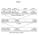
- a Dedicated Physical Channel (DPCH) comprises three-layer structure of super frames, radio frames and time slots.
- Figs. 1 and 2 show two data structures of the DPCH.
- the first type is a Dedicated Physical Data Channel (DPDCH) for transferring dedicated data
- the second type is a Dedicated Control Channel (DPCCH) for transferring a control information.
- DPDCH Dedicated Physical Data Channel
- DPCCH Dedicated Control Channel
- Fig. 1 shows a data structure of an upward link DPCH according to the standard of 3GPP RAN
- Fig. 2 shows a data structure of a downward link DPCH
- the DPCCH includes a TFCI field in each time slot constituting a radio frame.
- information on a transmission format, i.e. TFCI is coded and inserted into each radio frame.
- the number of TFCI bits is variable from a minimum of 1 bit to a maximum of 10 bits, and the number of bits is determined from the point in time when a call starts through a signal processing of an upper layer.
- Different coding methods are applicable to the TFCI depending upon the number of bits. When the number of TFCI bits is less than 6, a bi-orthogonal coding or a first Reed-Muller coding is applicable. When the number of the TFCI bits is greater than 7, a second Reed-Muller coding is applicable.
- the coded TFCI undergoes a puncturing to generate a code word of 30 bit length.
- a TFCI code word is output through a bi-orthogonal coding.
- a (32, 6) coding is applicable to the bi-orthogonal coding.
- a padding procedure is first executed to supplement the deficient bit value with "0" from the Most Significant Bit (MSB). Thereafter, the TFCI code word is inserted into each time slot of a radio frame by two bits. However, the entire length is restricted to be 30 bits.
- the TFCI code word of 32 bits, which has been bi-orthogonal coded is punctured by 2 bits and inserted into each time slot.
- a TFCI code word is output through a second Reed-Muller coding.
- a (32, 10) coding is applicable to the second Reed-Muller coding.
- a padding procedure is first executed to supplement the deficient bits with "0" from the MSB.
- the Reed-Muller coded TFCI code word is referred to as a sub-code. Accordingly, the sub-code is punctured by 2 bits to also generate a TFCI code word of 30 bit length.
- Fig. 3 is a block diagram illustrating a channel coding process.
- Fig. 4 is a diagram showing a typical insertion of the coded TFCI code word into each time slot.
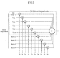
- Fig. 5 is a diagram illustrating an encoding structure for generating a (32, 10) TFCI code word according to the conventional second Reed-Muller coding.
- the TFCI bits variable from 1 to 10 bits are input to an encoder.
- the input data bit is lineally combined with 10 basis sequences.
- the basis sequences (32 element vectors) used for the linear combination comprises of a uniform code, in which all bit values are "1"; five orthogonal variable spreading factor codes represented by ⁇ C32, 1, C32, 2, C32, 4, C32, 8, C32, 16 ⁇ as shown in Table 1; and four mask codes represented by ⁇ Mask1, Mask2, Mask3, Mask4 ⁇ as shown in Table 2.
- M i,0 is the uniform code
- M i,1 ⁇ M i,5 respectively corresponds to C 32,1 , C 32,2 .
- M i,6 ⁇ M i,9 respectively corresponds to Mask1 ⁇ Mask4.
- the TFCI bits are lineally combined with the basis sequences described above and can be expressed by Equation 1, in which a 0 represents the Least Significant Bit (LSB), while a n-1 represents the MSB. a n - 1 , a n - 2 , ... , a 1 , a 0 n ⁇ 10
- a TFCI code word of 30 bit length is subsequently output by puncturing the first and the 17 th bits from the (32, 10) sub-code generated by the linear combination.
- the output TFCI code word of 30 bit length can be expressed by Equation 2: b 0 , b 1 , b 2 ... ... , b 28 , b 29
- Equation 1 the TFCI bits are input as expressed by Equation 1 are encoded by Equation 3 below to output the TFCI code word as expressed by Equation 2:
- Equation 3 the TFCI code word as expressed by Equation 2:
- the TFCI encoding according to the technology in the related art as described above poses the following problems.
- the pattern of the TFCI bits input for encoding are improper because of the padding procedure necessary when the TFCI bits are input for coding.
- a padding procedure is typically executed to supplement the deficient bit values with "0" from the MSB. Therefore, a complex decoding procedure is necessary to decode the encoded and transmitted TFCI code words at a receiving party. Namely, a bi-orthogonal coding is necessary even when the input TFCI bits is less than 6.
- the receiving party needs to perform a priority check to confirm from which set the OVSF code, used for the encoding, has been selected between two OVSF code sets which are in binary complement relations. As a result, additional process and hardware are required.
- a minimum hamming distance loss is up to 2 at maximum.
- one bit is punctured in a (16, 5) code word to generate a (15, 5) TFCI code word. In such case, a minimum hamming distance loss also occurs.
- an object of the present invention is to solve at least the problems and disadvantages of the related art.
- an object of the present invention is to allow an easy decoding of TFCI in a mobile telecommunicaiton system of the third generation under a W-CDMA standard.
- Another object of the present invention to provide an optimal matrix for basis sequences for TFCI coding.
- a still another object of the present invention to provide a method for encoding the TFCI with an optimal matrix for basis sequences.
- a further object of the present invention to provide an optimal matrix for basis sequences for TFCI coding which can maximize a minimum hamming distance with respect to a TFCI code word when inserting one or two bits into each time slot and transmitting after puncturing the TFCI code word used in the mobile telecommunication system under the W-CDMA standard.
- a still further object of the present invention to provide a method for encoding the TFCI with an optimal matrix for basis sequences which can maximize a minimum hamming distance with respect to a TFCI code word when inserting one or two bits into each time slot and transmitting after puncturing the TFCI code word used in the mobile telecommunication system under the W-CDMA standard.
- the TFCI is not more than 10 bits, it is padded with zeros to 10 bits by setting the most significant bits to zero if the bits are less than 10.
- the resultant 10 bit TFCI is encoded by the (32,10) sub-code of second order Reed-Muller code.
- the transmitted code words are linearly combined with 10 basis sequences: ⁇ M 0 , M 1 , ..., M 9 ⁇ .
- the basis sequences are linearly combined with TFCI bits as M 0 to the least significant bit and M 9 to the most significant bit.
- W-CDMA FDD Wide-band Code Divisional Multiple Access Frequency Division Duplex
- a method for encoding the TFCI comprises determining the number of TFCI bits; Repeating a 0 32 times for coding, if the TFCI consist of 1 bit; and linearly mapping the TFCI information bits a 0 , a 1 , a 2 , a 3 , a 4 , a 5 , a 6 , a 7 , a 8 , a 9 (a 0 is LSB and a 9 is MSB) to the basis sequences, if the TFCI consist of more than 2 bits.
- a method according to th present invention for encoding TFCI in split mode comprises determining the number of TFCI bits; Repeating a 0 16 times for coding, if the TFCI consist of 1 bit; and linearly mapping the TFCI information bits a 0 , a 1 , a 2 , a 3 , a 4 (a 0 is LSB and a 4 is MSB) to the basis sequences, if the TFCI consist of more than 2 bits.
- bi-orthogonal coding which is the first order Reed-Muller coding
- the second order Reed-Muller coding were applicable according to the number of bits of the TFCI bits input for the TFCI encoding.
- the bit patterns shown in Fig. 6 is applied so that only an OVSF coding rather than the bi-orthogonal coding can be applicable.
- Bit patterns different from the conventional bit patterns are also applied when the number of bits of the TFCI bits is greater than 6, depending on the cases.
- Fig. 6 is a pattern of TFCI bits applicable to the TFCI encoding according to the present invention
- Fig. 7 is a diagram illustrating a structure of the conventional TFCI encoder, to which the TFCI bit patterns according to the present invention are applicable.
- a bit pattern in which the deficient bit values has been supplemented with "0" from the MSB (a 5 ), unlike the prior bit pattern, and has been barrel-shifted becomes an input of the TFCI encoding to perform the OVSF coding without the bi-orthogonal coding.
- the number of the input TFCI bits is greater than 6, a barrel-shifted bit pattern of the prior bit pattern for 6 bits of the lower side, while the same bit pattern as the prior bit pattern is input to the 4 bits of the upper side (the TFCI bits linearly combined with the mask code of the basis sequences).
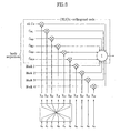
- Figs. 8 and 9 show the construction of hardware for performing the TFCI encoding, to which the bit pattern of Fig. 6 is applied.
- Fig. 8 is a diagram illustrating a detailed structure of the conventional TFCI encoder when the exchanged TFCI bits of Fig. 6 according to the present invention is applicable
- Fig. 9 is a block diagram illustrating the structure of TFCI encoder when the TFCI bits pattern of Fig. 6 is applied according to the present invention.
- Figs. 8 and 9 when the number of bits of the input TFCI bits is less than 6, a simple hardware has been added to allow the OVSF encoding.
- the TFCI bit patterns input to the TFCI encoder as shown in Fig. 7 can be expressed by Equation 4, where X i represents an aggregate composed of ten elements input to the TFCI encoder, i.e. a vector representing each TFCI bits.
- Fig. 6 is one of a detailed pattern expressed by the Equation 4.
- the TFCI encoder performs coding as follows with respect to each input. First, when the number of bits of the TFCI determined by the upper layer is less than 6, the OVSF coding is performed. Second, when the number of bits of the TFCI determined by the upper layer is 6, the bi-orthogonal coding, which is the first order Reed-Muller coding, is performed. Third, when the number of bits of the TFCI determined by the upper layer is greater than 6, the second order Reed-Muller coding is performed.
- the TFCI code word generated by the above coding in accordance with the number of input bits of each TFCI is transmitted to the receiving party. The receiving party then decodes the same.
- an OVSF coding is directly performed without the bi-orthogonal coding when the number of bits of the input TFCI bits is less than 6.
- the receiving party need not undergo a priority check to detect the set to which the OVSF code used for the encoding belongs from the two OVSF code sets that are in binary complement relations.
- Fig. 10a to 10c are diagrams illustrating structures of a decoder in accordance with the number of input bits of the TFCI according to the present invention.
- Fig. 10a shows a structure of a decoder according to the present invention when the number of input bits of the TFCI is greater than 6.
- the receiving party first multiplies the TFCI code word r(t) by "a 6 M 1 +a 7 M 2 +a 8 M 3 +a 9 M 4 ,” through multiplier 10.
- the TFCI code word r(t) has been transmitted after the second Reed-Muller coding and puncturing, and "a 6 M 1 +a 7 M 2 +a 8 M 3 +a 9 M 4 " has been obtained by linearly combining four or less of mask codes M 1 , M 2 , M 3 , M 4 among the basis sequences with 4 bits a 6 , a 7 , a 8 , a 9 of the upper side of the TFCI bits in the course of encoding by the sending party. Thereafter, decoding is performed through a Fast Hadamard Transform (FHT) decoding block 11.
- FHT Fast Hadamard Transform
- the decoded and transformed code word is converted to an OVSF code index in the index conversion block 12.
- the code index conversion is required to obtain the correct TFCI from the TFCI code word received because the relation between the Hadamard code index and the OVSF code index is in a base inversion (index conversion).
- information on the code index can be obtained.
- a priority checking block 13 is necessary because the receiving part has no information that the set to which the OVSF code used for the encoding belongs to from the two OVSF code sets that are in binary complement relations. That is, the code word used for the encoding has been selected between the two OVSF code sets that are in binary complement relations in accordance with the least significant bit (a 0 ) of the transmitter.
- the output of the priority checking block 13 is stored in a storage and comparison block 14.
- the outputs of the priority checking block 13 is stored for all other combinations of "a 6 , a 7 , a 8 , a 9 " by repeating the procedures of above blocks.
- OVSF codes and a uniform code of "a 0 , a 1 , a 2 , a 3 , a 4 , a 5 " which has a maximum likelihood to a particular combination that of "a 6 , a 7 , a 8 , a 9 " are then selected through a comparison procedure, thereby restoring the desired TFCI information bits "a 0 , a 1 , a 2 , a 3 , a 4 , as, a 6 , a 7 , a 8 , a 9 " ( a 0 is LSB and a 9 is MSB).
- Fig. 10b shows a decoder structure according to the present invention when the number of input bit of the TFCI bits of each type is less than 6.
- the receiving party first decodes the TFCI code word r(t), which has been transmitted after the OVSF coding and puncturing, through an FHT decoding block 21.
- the decoded and transformed code word is converted to an OVSF code index in the index conversion block (not shown in the drawings). Because the relation between the Hadamard code index and the OVSF code index is a base inversion, the code index conversion described above is required to obtain correct TFCI from the TFCI code word received.
- the TFCI bits which has undergone the base inversion in advance through barrel shifting, is OVSF-encoded and transmitted.
- the index conversion block is unnecessary.
- the OVSF coding is used. Therefore, priority checking block is unnecessary to detect the set to which the OVSF code used for the encoding belongs to from the two OVSF code sets that are in binary complement relations.
- the output of the FHT decoding block 21 is stored in a storage and comparison block 22, thereby restoring the desired TFCI bits "a 0 , a 1 , a 2 , a 3 , a 4 , a 5 .
- Fig. 10c shows a decoder structure according to the present invention when the number of input bit of the TFCI bits is 6.
- the receiving party first decodes the TFCI code word r(t), which has been transmitted after the first order Reed-Muller coding (bi-orthogonal coding) and puncturing, through an FHT decoding block 31.
- the decoded and transformed code word is converted to an OVSF code index in the index conversion block (not shown in the drawings). Because the relation between the Hadamard code index and the OVSF code index is a base inversion, the code index conversion described above is required in order to obtain correct TFCI from the TFCI code word received.
- the TFCI bits which has undergone the base inversion in advance through barrel shifting, is OVSF-encoded and transmitted.
- the index conversion block is also unnecessary.
- a priority checking block 32 is implemented to determine which OVSF code was used for encoding between the two OVSF code sets that are in binary complement relations. The reason is because either one of the two OVSF code sets that are in binary complement relations is selected by the sending party according to the bit value of a 0 , which is the LSB.
- the output of the priority checking block 32 is stored in a storage and comparison block 33, thereby restoring the desired TFCI bits "a 0 , a 1 , a 2 , a 3 , a 4 , a 5 .”
- Equation 7 the code having a bit length of 32 bits generated by the Rademacher function and a code generated by the Hadamard function are in base inversion (i.e. index conversion) relations as expressed by Equation 7.
- R ⁇ 1 H ⁇ 5 , 16
- R ⁇ 2 H ⁇ 5 , 8
- R ⁇ 3 H ⁇ 5 , 4
- R ⁇ 4 H ⁇ 5 , 2
- R ⁇ 5 H ⁇ 5 , 1
- the OVSF code and the Hadamard code are in base inversion relations as expressed by Equation 8.
- C ⁇ 32 , X ⁇ 1 , X ⁇ 2 , X ⁇ 3 , X ⁇ 4 , X ⁇ 5 ⁇ 2 H ⁇ 5 , X ⁇ 5 , X ⁇ 4 , X ⁇ 3 , X ⁇ 2 , X ⁇ 1 ⁇ 2
- index conversion must be performed when decoding the conventional TFCI bits through FHT after encoding and transmitting the TFCI bits as suggested by the present invention through FHT after encoding.
- the receiving party need not perform the index conversion.
- the present invention can be implemented by changing the matrix of base sequences of TFCI encoder.
- the first method to build a matrix according to the present invention is to shift the construction of the basis sequences linearly combined with the conventional TFCI bit patterns while maintaining the prior patterns of the input TFCI bits as shown in Table 4 below.
- Table 4 Uniform C 32,16 code C 32,8 C 32,1 C 32,4 C 32,2 C 32,2 C 32,4 ⁇ C 32,1 C 32,8 Uniform C 32,16 code Mask1 Mask1 Mask2 Mask2 Mask3 Mask3 Mask4 Mask4
- the second method is to apply the Hadamard code, which is in index conversion relations with the OVSF code index rather than the OVSF code, of the basis sequences linearly combined with the prior TFCI bits patterns while maintaining the prior patterns of the input TFCI bits, and to shift the basis sequences as shown in Table 5 below.
- Table 5 Uniform H 5,1 code H 5,2 C 32,1 H 5,4 C 32,2 H 5,8 C 32,4 > H 5,16 C 32,8 Uniform C 32,16 code Mask 1 Mask 1 Mask2 Mask2 Mask3 Mask3 Mask4 Mask4
- the present invention further utilizes the method of linearly combining a 0 with uniform codes of all 1's, as in the conventional method, instead of applying the pattern as shown in Fig. 6 when the number of bits of the TFCI input for encoding is 1, as well as the method of linearly combining the bit patterns of each type as shown in Fig. 6 in other cases, i.e. when the number of bits of the TFCI bits input for encoding is greater than 2.
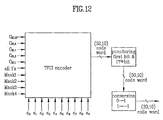
- Fig. 11 is a structure of a transmitting party of the TFCI according to a first embodiment of the present invention while Fig. 12 shows a structure of the TFCI transmitting party according to the second embodiment of the present invention.
- Fig. 11 shows a hardware construction for encoding and transmitting the TFCI, to which the bit pattern of Fig. 6 is applicable.
- Fig. 12 shows different arrangements of the ten basis sequences linearly combined with the input data bit, while inputting the prior TFCI bits patterns as they are.
- Fig. 12 shows a barrel shifting of the symbol codes having all bit values of "1" except the four mask codes (Mask1, Mask2, Mask3, Mask4) among the basis sequences used for linear combination as well as five OVSF codes (C32,1, C32,2, C32,4, C32,8, C32,16), and linearly combining the same with the input data bit.
- the TFCI bits patterns input to the TFCI encoder can be expressed by Equation 4 described above.
- the following coding is performed in the TFCI encoder with respect to each input as explained with reference to Fig. 8 .
- the OVSF coding is performed when the number of bits of the TFCI bits determined by the upper layer is less than 6.
- the bi-orthogonal coding which is the first order Reed-Muller coding, is performed when the number of the TFCI bits determined by the upper layer signalling is 6.
- the second order Reed-Muller coding is performed when the number of bits of the TFCI bits determined by the upper layer is greater than 6.
- the code word of 32 bit length generated by coding in accordance with the input bit numbers of each TFCI bits becomes a code word of 30 bit length after the first and the 17 th bits are punctured.
- the code word is once again converted and transmitted.
- the receiving party then decodes the converted and transmitted code word.
- the bit of "0" is converted to "1,” and the bit of "1” is converted to "-1" in the punctured code word of 30 bit length.
- a decoding structure of the receiving party corresponding to TFCI encoder shown in Figs. 11 and 12 , will be described with reference to Fig. 13 .
- the decoding procedure of the TFCI code word by the receiving party will be described thereafter.
- Fig. 13 is a block diagram illustrating an optimal TFCI decoding procedure according to the present invention.
- the receiving party is unable to know whether the first and the 17 th bits of the code word of 32 bit length punctured by the sending party had a bit value of "1" or "0.”
- a code word of 32 bit length was produced by leaving a blank bit to a corresponding order and decoding when depuncturing a code word of 30 bit length received by the receiving party.
- the encoded and transmitted code word becomes a Hadamard code if the number of input TFCI bits is less than 6. Therefore, errors resulting from decoding can be reduced.
- the Hadamard code has the following characteristics.
- the code of 30 bit length received by the receiving party according to the present invention is depunctured by using the above characteristics of Hadamard code.
- depuncturing is performed in the following three manners.
- the receiving party knows that the first and the 17 th bits punctured from the 32-bit code word by the sending party have bit values of "0,” and that the bit value "0" has been mapped and transmitted to "1.” Thus, the receiving party fills in the first and the 17 th bits with "H ,” which is a predetermined high bias value. (Case 1)
- the receiving party knows that the first bit punctured from the 32-bit code word by the sending party has a bit value of "0,” and that the bit value "0" has been mapped and transmitted to "1.” Thus, the receiving party fills in the first bit with "H” for the first bit. Since the receiving party does not know whether the 17 th bit has a bit value of "1" or "0,” the receiving party fills in the 17 th bit with "B,” which is a blank bit. (Case 2)
- the receiving party when the number of input TFCI bits is greater than 6, the receiving party is unable to know whether the first and the 17 th bits punctured from the 32-bit code word by the sending party had a bit value of "1" or "0.” Thus, the receiving party fills in the 17 th bit with "B.” (Case 3)
- the depuncturing block 10 of Fig. 13 in the receiving party performs a depuncturing (compensating punctured bits) in accordance with the number of input TFCI bits as described above. Thereafter, the TFCI decoder 20 performs a decoding based on the depunctured 32-bit code word as an input.
- the receiving party receives the code word R(t) of 30-bit length as expressed by Equation 9.
- R t R 2 R 3 .... R 16 R 18 .... R 31 R 32
- the Depuncturing block 10 then performs depuncturing in accordance with the number of bits of the input TFCI bits to output a code word of 32-bit length in accordance with each case as shown in Equations 10 to 12 (Case1, Case2, Case3).
- H R 2 R 3 .... R 16 H R 18 .... R 31 R 32 H R 2 R 3 .... R 16 H R 18 .... R 31 R 32 B R 2 R 3 .... R 16 B R 18 .... R 31 R 32
- the receiving party After having knowledge on the value of the bit punctured by the sending party, the receiving party produces a code word of 32-bit length by substituting the bit value for the corresponding bit position.
- the TFCI decoder 20 then performs a decoding based on the 32-bit length code word as an input, thereby restoring the desired TFCI bits.
- a TFCI encoding method according to the present invention by changing the matrix of base sequences of TFCI encoder will now be described in more detail.
- Table 6 shows the basis sequences used in the (32, 10) TFCI encoding
- Table 8 shows the basis sequences used for the (16, 5) TFCI encoding.
- Equation 13 the relations between the basis sequences in Table 6 and those in Table 3 can be expressed by Equation 13.
- S i , 5 M i , 0
- the first and the 17 th bits of M i,j is moved to the last two bits at S i,j
- the basis sequences linearly combined for encoding according to the present invention are applied in the following order: "Si, 0, Si, 1, Si, 2, Si, 3, Si, 4" corresponding to five OVSF codes represented by "C32, 1, C32, 2, C32, 4, C32, 8, C32, 16"; " Si,6, Si,7, Si, 8, Si, 9” corresponding to four mask codes represented by the conventional "Mask1, Mask2, Mask3, Mask4"; and "Si, 5" which is a single uniform code having all bit values of "1.”
- a conversion matrix for encoding a TFCI would include five column vectors of 32 elements of binary code derived from OVSF codes which are to be multiplied to lower bits of the TFCI, one column vector of 32 elements of 1, and four column vectors of 32 elements of binary code derived from mask codes which are to be multiplied to upper bits of the TFCI.
- the five column vectors are derived by moving a first element and a 17 th element of a normal 32 element OVSF code vectors to last two positions of the OVSF code vectors, as will be described in detail below.
- a column vector of the five column vectors which is to be multiplied to a least significant bit of the TFCI is derived from an OVSF code which alternates bits, element by element.
- Equation 14 is applicable when TFCI data bit index Z is "0 ⁇ Z ⁇ 8," while the uniform code is applicable when TFCI data bit index Z is "9,” i.e. only one TFCI bit is input. Accordingly, in the present method for transmitting the TFCI, the TFCI is coded by multiplying with the conversion matrix as describe above if the number of input TFCI bits are more than two or by repeating the input TFCI bit if the number of input TFCI is one bit.
- the TFCI code word encoded as described above is divided into fifteen double bits and inserted into each time slot for transmission, and thus the entire length thereof is fixed to be 30 bits. Accordingly, the encoded 32-bit length TFCI code word is punctured by 2 bits and inserted into each time slot. According to the prior specification of 3GPP standard, the 1 st and 17 th bits of (32,10) sub-code of second order Reed-Muller code word are punctured into (30,10) code word. The following shows the 1 st and 17 th bits of Hadamard codes of length 32.
- the present method punctures the last 31 st bit and the 32 nd bit among the 32-bit length TFCI code word, since the basis sequences had been rearranged to move the first bit to the 31 st bit and the 17 th to the 32 nd bit.
- the code bit having a value of "1" is punctured.
- no code bit having a value of " 1 " is punctured when the input TFCI data bit is ranged from a 0 to a 8 since the last 2 bits are punctured among the 32-bit lenght TFCI word. Therefore, a maximized minimum hamming distance is gained.
- the basis sequences linearly combined for encoding which are applicable according to the present invention, are "Si,0, Si,1, Si,2, Si,3, Si,4" corresponding to five OVSF codes expressed as "C32,1, C32,3, C32,4, C32,8, C32,16" from the top under the conventional art.
- a conversion matrix for encoding the TFCI includes four column vectors of 16 elements of binary code derived from codes orthogonal to one another which are to be multiplied to the lower bits of the TFCI and one column vector of 16 elements of 1. Also, as will be described below, the four column vectors are derived by moving a first element of normal 16 element orthogonal code vectors to last positions of the orthogonal code vectors, and a column vector of the four column vectors which is to be multiplied to a least significant bit of the TFCI is made from an orthogonal code which alternates bits, element by element.
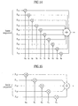
- Fig. 15 is a diagram illustrating a structure of the (16, 5) TFCI encoder according to the present invention.
- a z a 4 , . a 1 , a 0
- encoding is performed using Equation 16 according to the present invention.
- the (16, 5) TFCI code word encoded as described above is divided into 1 bit each, inserted into each time slot, and transmitted. Because the entire length is fixed to 15 bits, the encoded TFCI code word of 16 bit length is punctured for 1 bit, and inserted into each time slot. Here, the last 16 th bit among the TFCI code word of 16 bit length is punctured.
- the UTRAN operates as follows. If one of the links is associated with a DSCH, the TFCI code word may be split in such a way that the code word relevant for TFCI activity indication is not transmitted from every cell. The use of such a functionality shall be indicated by higher layer signalling.
- the TFCI bits are encoded using a (16, 5) bi-orthogonal (or first order Reed-Muller) code.
- the present invention has the following advantageous effects.
- the receiving party can decode an encoded and transmitted TFCI code word through a more simple procedure using an optimal TFCI encoding method.
- the receiving party performs depuncturing by substituting a high bias value for the bit position punctured by the sending party.
- the receiving party therefore is able to know the encoded code word, and may undergo a more simple procedure in decoding the transmitted code word.
- the hardware required can also be reduced, thereby reducing the cost.
- a maximized minimum hamming distance is gained with respect to the TFCI code word when inserting and transmitting the TFCI code word by 1 bit or 2 bits per time slot after puncturing the TFCI code word. The minimum hamming distance is thus maximized with respect to the TFCI code word and the performance of the entire system is enhanced.
Landscapes
- Engineering & Computer Science (AREA)
- Computer Networks & Wireless Communication (AREA)
- Signal Processing (AREA)
- Quality & Reliability (AREA)
- Compression, Expansion, Code Conversion, And Decoders (AREA)
- Dc Digital Transmission (AREA)
- Time-Division Multiplex Systems (AREA)
- Mobile Radio Communication Systems (AREA)
- Reduction Or Emphasis Of Bandwidth Of Signals (AREA)
- Radar Systems Or Details Thereof (AREA)
- Sorting Of Articles (AREA)
- Communication Control (AREA)
Applications Claiming Priority (4)
| Application Number | Priority Date | Filing Date | Title |
|---|---|---|---|
| KR1019990051361A KR100320431B1 (ko) | 1999-11-18 | 1999-11-18 | 최적의 전송 포맷 조합 식별자 엔코딩 방법 |
| KR10-1999-0052138A KR100382521B1 (ko) | 1999-11-23 | 1999-11-23 | 최적의 전송 포맷 조합 식별자 전송 방법 |
| KR10-2000-0005446A KR100451719B1 (ko) | 2000-02-03 | 2000-02-03 | 최적의 전송 포맷 조합 식별자 엔코딩 방법 |
| EP20000125148 EP1104130B1 (fr) | 1999-11-18 | 2000-11-17 | Méthode de codage et de transmission d'un indicateur de combinaison de format de transport |
Related Parent Applications (2)
| Application Number | Title | Priority Date | Filing Date |
|---|---|---|---|
| EP20000125148 Division EP1104130B1 (fr) | 1999-11-18 | 2000-11-17 | Méthode de codage et de transmission d'un indicateur de combinaison de format de transport |
| EP00125148.7 Division | 2000-11-17 |
Publications (3)
| Publication Number | Publication Date |
|---|---|
| EP2051427A2 true EP2051427A2 (fr) | 2009-04-22 |
| EP2051427A3 EP2051427A3 (fr) | 2009-09-23 |
| EP2051427B1 EP2051427B1 (fr) | 2010-07-28 |
Family
ID=27350095
Family Applications (3)
| Application Number | Title | Priority Date | Filing Date |
|---|---|---|---|
| EP20090001171 Expired - Lifetime EP2051427B1 (fr) | 1999-11-18 | 2000-11-17 | Procédé de codage et de transmission d'indicateur de combinaison de format de transport |
| EP20090012298 Expired - Lifetime EP2134022B1 (fr) | 1999-11-18 | 2000-11-17 | Procédé de codage et de transmission d'indicateur de combinaison de format de transport |
| EP20000125148 Expired - Lifetime EP1104130B1 (fr) | 1999-11-18 | 2000-11-17 | Méthode de codage et de transmission d'un indicateur de combinaison de format de transport |
Family Applications After (2)
| Application Number | Title | Priority Date | Filing Date |
|---|---|---|---|
| EP20090012298 Expired - Lifetime EP2134022B1 (fr) | 1999-11-18 | 2000-11-17 | Procédé de codage et de transmission d'indicateur de combinaison de format de transport |
| EP20000125148 Expired - Lifetime EP1104130B1 (fr) | 1999-11-18 | 2000-11-17 | Méthode de codage et de transmission d'un indicateur de combinaison de format de transport |
Country Status (6)
| Country | Link |
|---|---|
| US (4) | US6813506B1 (fr) |
| EP (3) | EP2051427B1 (fr) |
| JP (1) | JP3847078B2 (fr) |
| CN (1) | CN100389548C (fr) |
| AT (3) | ATE525822T1 (fr) |
| DE (2) | DE60044759D1 (fr) |
Families Citing this family (42)
| Publication number | Priority date | Publication date | Assignee | Title |
|---|---|---|---|---|
| ES2228562T7 (es) * | 1999-07-06 | 2014-11-26 | Samsung Electronics Co., Ltd. | Aparato de codificación de un indicador de combinación de formato de transporte para un sistema de comunicación móvil CDMA. |
| DE60044759D1 (de) * | 1999-11-18 | 2010-09-09 | Lg Electronics Inc | Verfahren zur Kodierung und Übertragung von Formatkombinationsindikatoren |
| KR100407942B1 (ko) | 1999-11-19 | 2003-12-01 | 엘지전자 주식회사 | 이동통신 시스템에서 전송 포맷 조합 지시자를 전송하는 방법 |
| EP1190496B1 (fr) * | 2000-02-17 | 2004-10-27 | Samsung Electronics Co., Ltd. | Dispositif et procede d'assignation d'une voie commune de transmission par paquets dans un systeme de communication amcr |
| KR100421164B1 (ko) * | 2000-06-12 | 2004-03-04 | 삼성전자주식회사 | 이동통신시스템에서 전송율 정보 부호화 및 복호화 장치 및 방법 |
| JP3399923B2 (ja) * | 2000-11-29 | 2003-04-28 | 松下電器産業株式会社 | 通信端末装置および通信端末装置における復号化方法 |
| DE10101703A1 (de) * | 2001-01-15 | 2002-07-18 | Philips Corp Intellectual Pty | Drahtloses Netzwerk mit einer Auswahl von Transport-Format-Kombinationen |
| JP3599713B2 (ja) * | 2001-02-27 | 2004-12-08 | 三星電子株式会社 | 分割モードによる伝送形式組合せ表示ビットの伝送装置及び方法 |
| WO2002091656A1 (fr) * | 2001-04-25 | 2002-11-14 | Mitsubishi Denki Kabushiki Kaisha | Procede de decodage de donnees |
| CA2391841C (fr) | 2001-06-28 | 2006-05-16 | Samsung Electronics Co., Ltd. | Appareil et methode de transmission de bits tfci pour un mode de fractionnement permanent dans un systeme de communication mobile amdc |
| GB2380105B (en) * | 2001-07-09 | 2003-12-10 | Samsung Electronics Co Ltd | Apparatus and method for symbol mapping tfci bits for a hard split mode in a cdma mobile communication system |
| KR100402786B1 (ko) * | 2001-07-30 | 2003-10-22 | 한국전자통신연구원 | 무선 통신 단말기에서의 전송율 정보 매핑 장치 및 그 방법 |
| JP4318412B2 (ja) | 2001-08-08 | 2009-08-26 | 富士通株式会社 | 通信システムにおける送受信装置及び送受信方法 |
| GB2379839B (en) * | 2001-09-12 | 2004-07-21 | Ubinetics Ltd | Apparatus and methods for block encoding data |
| US6552996B2 (en) * | 2001-09-18 | 2003-04-22 | Interdigital Communications Corporation | OVSF code system and methods |
| DE10159637C1 (de) * | 2001-12-05 | 2003-08-07 | Siemens Ag | Verfahren zur Zuweisung von Übertragungskanälen in einer Mobilfunkzelle für einen Multicast-Dienst |
| JP3594086B2 (ja) | 2002-02-08 | 2004-11-24 | ソニー株式会社 | 移動体通信における情報多重方法、伝送フォーマット組合せ識別子のデコード方法および装置、移動局装置、基地局装置および移動体通信システム |
| US7292552B2 (en) | 2002-03-14 | 2007-11-06 | Qualcomm Incorporated | Method and apparatus for reducing interference in a wireless communication system |
| JP2003280754A (ja) * | 2002-03-25 | 2003-10-02 | Nec Corp | 隠蔽化ソースプログラム、ソースプログラム変換方法及び装置並びにソース変換プログラム |
| CN1640172A (zh) * | 2002-07-09 | 2005-07-13 | 富士通株式会社 | 通信系统及数据收发装置、数据收发方法 |
| JP3742055B2 (ja) | 2002-11-27 | 2006-02-01 | 埼玉日本電気株式会社 | 無線基地局装置、及びそれに用いるtfci復号特性を利用する復号装置とその復号方法 |
| TWI342686B (en) | 2002-12-04 | 2011-05-21 | Interdigital Tech Corp | Reliability detection of channel quality indicator (cqi) and application to outer loop power control |
| KR100548346B1 (ko) * | 2003-05-13 | 2006-02-02 | 엘지전자 주식회사 | 이동통신 시스템에서의 tfci 전송 방법 |
| US7474643B2 (en) * | 2003-10-02 | 2009-01-06 | Qualcomm Incorporated | Systems and methods for communicating control data using multiple slot formats |
| UA83256C2 (ru) * | 2003-10-02 | 2008-06-25 | Квелкомм Инкорпорэйтед | Система и способ мультиплексирования данных управления для множества каналов передачи данных в одном канале управления (варианты) |
| US7283492B2 (en) * | 2003-10-02 | 2007-10-16 | Qualcomm Incorporated | Systems and methods for multiplexing control information onto a physical data channel |
| US7721179B2 (en) * | 2004-09-15 | 2010-05-18 | Samsung Electronics Co., Ltd. | Method and apparatus for encoding/decoding transmission information in mobile telecommunication system |
| CN100411476C (zh) * | 2004-09-20 | 2008-08-13 | 华为技术有限公司 | 一种宽带码分多址系统中上行增强链路信令编码方法 |
| CN1798446B (zh) | 2004-12-29 | 2010-09-29 | 北京三星通信技术研究有限公司 | 在Mac-ePDU 中传输短信令的方法 |
| US8351401B2 (en) * | 2005-02-25 | 2013-01-08 | Nec Corporation | Code sequence transmission method, wireless communication system, transmitter, and receiver |
| US7934137B2 (en) * | 2006-02-06 | 2011-04-26 | Qualcomm Incorporated | Message remapping and encoding |
| EP2076989A2 (fr) * | 2006-10-02 | 2009-07-08 | Interdigital Technology Corporation | Procédé et appareil permettant de procéder au codage d'un indicateur de qualité de canal et au codage préalable de bits d'informations de contrôle |
| JP4482023B2 (ja) * | 2007-11-08 | 2010-06-16 | 富士通株式会社 | 無線装置におけるチャネル符号化及び復号化装置 |
| US8543885B2 (en) * | 2007-11-18 | 2013-09-24 | Lg Electronics Inc. | Methods of joint coding in mobile communication system |
| HUE038989T2 (hu) | 2007-12-24 | 2018-12-28 | Lg Electronics Inc | Csatorna kódolás egy (32,11) blokk kód és egy változó O hosszúságú (20, O) blokk kód használatával |
| TWI419478B (zh) * | 2007-12-24 | 2013-12-11 | Lg Electronics Inc | 使用塊碼之可變長度資訊的通道編碼方法 |
| KR100970645B1 (ko) | 2007-12-24 | 2010-07-15 | 엘지전자 주식회사 | 블록 코드를 이용한 다양한 길이를 가진 정보의 채널 코딩방법 |
| WO2009082146A2 (fr) * | 2007-12-24 | 2009-07-02 | Lg Electronics Inc. | Procédé de codage de canal sur des informations de longueurs variables au moyen d'un code de blocs |
| US9130712B2 (en) * | 2008-02-29 | 2015-09-08 | Google Technology Holdings LLC | Physical channel segmentation in wireless communication system |
| US20110182169A1 (en) * | 2009-09-13 | 2011-07-28 | Research Institute Of Tsinghua University In Shenzhen | Code division multiplexing method and system |
| KR102453472B1 (ko) | 2015-02-27 | 2022-10-14 | 한국전자통신연구원 | 가변 길이 시그널링 정보 부호화를 위한 패리티 펑처링 장치 및 이를 이용한 패리티 펑처링 방법 |
| RU2699589C1 (ru) * | 2019-02-07 | 2019-09-06 | Российская Федерация, от имени которой выступает Государственная корпорация по атомной энергии "Росатом" | Способ динамического преобразования данных при хранении и передаче |
Citations (2)
| Publication number | Priority date | Publication date | Assignee | Title |
|---|---|---|---|---|
| WO2000033516A1 (fr) * | 1998-11-30 | 2000-06-08 | Siemens Aktiengesellschaft | Procede et systeme de communication destine a transmettre des donnees d'une association de plusieurs services par des canaux physiques utilises en commun |
| EP1009174A2 (fr) * | 1998-12-09 | 2000-06-14 | Lg Electronics Inc. | Dispositif et procédé de réalisation de services multiples TFCI dans un system de communication mobile |
Family Cites Families (18)
| Publication number | Priority date | Publication date | Assignee | Title |
|---|---|---|---|---|
| US5511073A (en) * | 1990-06-25 | 1996-04-23 | Qualcomm Incorporated | Method and apparatus for the formatting of data for transmission |
| JPH07202941A (ja) * | 1994-01-10 | 1995-08-04 | Matsushita Electric Ind Co Ltd | ディジタルデータ伝送方法 |
| US5938787A (en) * | 1997-03-27 | 1999-08-17 | Ericsson Inc. | Communications systems and methods employing code rate partitioning with nonorthogonal modulation |
| FI106667B (fi) * | 1998-02-16 | 2001-03-15 | Nokia Networks Oy | Menetelmä, radioverkko-ohjain ja järjestelmä ainakin kahden radioverkko-ohjaimen kautta kulkevan makrodiversiteettiyhteyden kontrolloimiseksi solukkoradiojärjestelmässä |
| US6202189B1 (en) | 1998-12-17 | 2001-03-13 | Teledesic Llc | Punctured serial concatenated convolutional coding system and method for low-earth-orbit satellite data communication |
| US6356925B1 (en) * | 1999-03-16 | 2002-03-12 | International Business Machines Corporation | Check digit method and system for detection of transposition errors |
| US6693952B1 (en) * | 1999-03-16 | 2004-02-17 | Lucent Technologies Inc. | Dynamic code allocation for downlink shared channels |
| GB2349042B (en) * | 1999-04-12 | 2003-07-23 | Motorola Ltd | A communication apparatus and method of format adaptation therfor |
| ES2228562T7 (es) | 1999-07-06 | 2014-11-26 | Samsung Electronics Co., Ltd. | Aparato de codificación de un indicador de combinación de formato de transporte para un sistema de comunicación móvil CDMA. |
| US7054296B1 (en) * | 1999-08-04 | 2006-05-30 | Parkervision, Inc. | Wireless local area network (WLAN) technology and applications including techniques of universal frequency translation |
| FR2797736B1 (fr) * | 1999-08-19 | 2001-10-12 | Mitsubishi Electric France | Procede de configuration d'un systeme de telecommunications |
| US20040028071A1 (en) | 1999-09-10 | 2004-02-12 | Interval Research Corporation, A Washington Corporation | Apparatus and method for managing variable-sized data slots with timestamp counters within a TDMA frame |
| DE60044759D1 (de) * | 1999-11-18 | 2010-09-09 | Lg Electronics Inc | Verfahren zur Kodierung und Übertragung von Formatkombinationsindikatoren |
| US20020108090A1 (en) * | 2001-02-05 | 2002-08-08 | Cute Ltd. | Blind transport format detection of turbo-coded data |
| EP1292057A4 (fr) * | 2001-02-06 | 2005-06-22 | Mitsubishi Electric Corp | Procede de correction d'erreur et de decodage |
| CA2371556C (fr) * | 2001-02-19 | 2005-08-23 | Samsung Electronics Co., Ltd. | Appareil de multiplexage dpch et methode de commande de puissance de boucle exterieure dans un systeme de communication amrc large bande |
| JP4318412B2 (ja) * | 2001-08-08 | 2009-08-26 | 富士通株式会社 | 通信システムにおける送受信装置及び送受信方法 |
| JP3742055B2 (ja) * | 2002-11-27 | 2006-02-01 | 埼玉日本電気株式会社 | 無線基地局装置、及びそれに用いるtfci復号特性を利用する復号装置とその復号方法 |
-
2000
- 2000-11-17 DE DE60044759T patent/DE60044759D1/de not_active Expired - Lifetime
- 2000-11-17 AT AT09012298T patent/ATE525822T1/de not_active IP Right Cessation
- 2000-11-17 AT AT09001171T patent/ATE476027T1/de not_active IP Right Cessation
- 2000-11-17 EP EP20090001171 patent/EP2051427B1/fr not_active Expired - Lifetime
- 2000-11-17 EP EP20090012298 patent/EP2134022B1/fr not_active Expired - Lifetime
- 2000-11-17 EP EP20000125148 patent/EP1104130B1/fr not_active Expired - Lifetime
- 2000-11-17 AT AT00125148T patent/ATE456205T1/de not_active IP Right Cessation
- 2000-11-17 DE DE60043720T patent/DE60043720D1/de not_active Expired - Lifetime
- 2000-11-17 US US09/714,439 patent/US6813506B1/en not_active Expired - Lifetime
- 2000-11-20 CN CNB001324233A patent/CN100389548C/zh not_active Expired - Lifetime
- 2000-11-20 JP JP2000353640A patent/JP3847078B2/ja not_active Expired - Lifetime
-
2004
- 2004-09-28 US US10/950,788 patent/US7526299B2/en not_active Expired - Lifetime
-
2009
- 2009-03-06 US US12/399,383 patent/US8265666B2/en not_active Expired - Lifetime
- 2009-03-06 US US12/399,422 patent/US8310945B2/en not_active Expired - Lifetime
Patent Citations (2)
| Publication number | Priority date | Publication date | Assignee | Title |
|---|---|---|---|---|
| WO2000033516A1 (fr) * | 1998-11-30 | 2000-06-08 | Siemens Aktiengesellschaft | Procede et systeme de communication destine a transmettre des donnees d'une association de plusieurs services par des canaux physiques utilises en commun |
| EP1009174A2 (fr) * | 1998-12-09 | 2000-06-14 | Lg Electronics Inc. | Dispositif et procédé de réalisation de services multiples TFCI dans un system de communication mobile |
Non-Patent Citations (2)
| Title |
|---|
| "New Optimal Coding for extended TFCI with almost no complexity increase (rev 2)" TSG-RAN WORKING GROUP 1 MEETING, XX, XX, no. #7, 30 August 1999 (1999-08-30), pages 1-16, XP002254198 * |
| SAMSUNG: "Text proposal regarding TFCI coding for FDD" TSG-RAN WORKING GROUP 1 MEETING #7, XX, XX, 30 August 1999 (1999-08-30), XP002344344 * |
Also Published As
| Publication number | Publication date |
|---|---|
| ATE525822T1 (de) | 2011-10-15 |
| EP2134022A2 (fr) | 2009-12-16 |
| EP2134022A3 (fr) | 2010-08-25 |
| EP1104130A2 (fr) | 2001-05-30 |
| ATE476027T1 (de) | 2010-08-15 |
| US20090180461A1 (en) | 2009-07-16 |
| EP2051427B1 (fr) | 2010-07-28 |
| DE60043720D1 (de) | 2010-03-11 |
| EP2051427A3 (fr) | 2009-09-23 |
| US6813506B1 (en) | 2004-11-02 |
| EP1104130A3 (fr) | 2006-02-01 |
| US8265666B2 (en) | 2012-09-11 |
| US20090168740A1 (en) | 2009-07-02 |
| JP2001245359A (ja) | 2001-09-07 |
| EP1104130B1 (fr) | 2010-01-20 |
| EP2134022B1 (fr) | 2011-09-21 |
| US8310945B2 (en) | 2012-11-13 |
| US7526299B2 (en) | 2009-04-28 |
| US20050079881A1 (en) | 2005-04-14 |
| JP3847078B2 (ja) | 2006-11-15 |
| DE60044759D1 (de) | 2010-09-09 |
| ATE456205T1 (de) | 2010-02-15 |
| CN100389548C (zh) | 2008-05-21 |
| CN1300142A (zh) | 2001-06-20 |
Similar Documents
| Publication | Publication Date | Title |
|---|---|---|
| EP2134022B1 (fr) | Procédé de codage et de transmission d'indicateur de combinaison de format de transport | |
| EP2134038B1 (fr) | Procédé d'amélioration de la performance de transport TFCI | |
| US9119198B2 (en) | Method for transmitting control information, and method for generating codeword for the same | |
| US6757536B1 (en) | Method of providing site selection diversity in mobile communication system | |
| EP1400027B1 (fr) | Procede de transmission de bits tfci pour un mode partage "dur" dans un systeme de communication mobile amcr | |
| MXPA04007853A (es) | Metodo de codificacion para informacion de calidad de un canal para hs-dpcch. | |
| EP1307968B1 (fr) | Procede et appareil de perforation de symboles de code dans un systeme de communication | |
| EP1257080B1 (fr) | Codeur/decodeur de canaux et procédé dans un système de communication mobile AMDC | |
| EP1244237B1 (fr) | Procédé et dispositif de codage/décodage dans un système de communication CDMA ( AMRC ) | |
| US6961387B2 (en) | Apparatus and method for coding/decoding optimal (11,5) codeword in a mobile communication system | |
| KR100694397B1 (ko) | 업링크 동기식 전송방식을 위한 전용채널의 tab 결합방법 | |
| EP1330887B1 (fr) | Procede et arrangement de protection optimale de bits contre des erreurs de transmission | |
| KR100320431B1 (ko) | 최적의 전송 포맷 조합 식별자 엔코딩 방법 | |
| EP0588307A2 (fr) | Système de transmission des séquences de bits d'information | |
| KR100382521B1 (ko) | 최적의 전송 포맷 조합 식별자 전송 방법 | |
| EP2157701B1 (fr) | Procédé et appareil de perforation de symboles de codes dans un système de communications | |
| KR100451719B1 (ko) | 최적의 전송 포맷 조합 식별자 엔코딩 방법 | |
| KR20030076012A (ko) | 물리채널 전송 포맷 검출 방법 | |
| KR20110001630A (ko) | 전송 포맷 조합 식별자 부호화 방법 |
Legal Events
| Date | Code | Title | Description |
|---|---|---|---|
| PUAI | Public reference made under article 153(3) epc to a published international application that has entered the european phase |
Free format text: ORIGINAL CODE: 0009012 |
|
| 17P | Request for examination filed |
Effective date: 20090128 |
|
| AC | Divisional application: reference to earlier application |
Ref document number: 1104130 Country of ref document: EP Kind code of ref document: P |
|
| AK | Designated contracting states |
Kind code of ref document: A2 Designated state(s): AT BE CH CY DE DK ES FI FR GB GR IE IT LI LU MC NL PT SE TR |
|
| PUAL | Search report despatched |
Free format text: ORIGINAL CODE: 0009013 |
|
| AK | Designated contracting states |
Kind code of ref document: A3 Designated state(s): AT BE CH CY DE DK ES FI FR GB GR IE IT LI LU MC NL PT SE TR |
|
| GRAP | Despatch of communication of intention to grant a patent |
Free format text: ORIGINAL CODE: EPIDOSNIGR1 |
|
| AKX | Designation fees paid |
Designated state(s): AT BE CH CY DE DK ES FI FR GB GR IE IT LI LU MC NL PT SE TR |
|
| GRAS | Grant fee paid |
Free format text: ORIGINAL CODE: EPIDOSNIGR3 |
|
| GRAA | (expected) grant |
Free format text: ORIGINAL CODE: 0009210 |
|
| AC | Divisional application: reference to earlier application |
Ref document number: 1104130 Country of ref document: EP Kind code of ref document: P |
|
| AK | Designated contracting states |
Kind code of ref document: B1 Designated state(s): AT BE CH CY DE DK ES FI FR GB GR IE IT LI LU MC NL PT SE TR |
|
| REG | Reference to a national code |
Ref country code: GB Ref legal event code: FG4D |
|
| REG | Reference to a national code |
Ref country code: CH Ref legal event code: EP |
|
| REG | Reference to a national code |
Ref country code: NL Ref legal event code: T3 |
|
| REG | Reference to a national code |
Ref country code: IE Ref legal event code: FG4D |
|
| REF | Corresponds to: |
Ref document number: 60044759 Country of ref document: DE Date of ref document: 20100909 Kind code of ref document: P |
|
| PG25 | Lapsed in a contracting state [announced via postgrant information from national office to epo] |
Ref country code: AT Free format text: LAPSE BECAUSE OF FAILURE TO SUBMIT A TRANSLATION OF THE DESCRIPTION OR TO PAY THE FEE WITHIN THE PRESCRIBED TIME-LIMIT Effective date: 20100728 |
|
| PG25 | Lapsed in a contracting state [announced via postgrant information from national office to epo] |
Ref country code: CY Free format text: LAPSE BECAUSE OF FAILURE TO SUBMIT A TRANSLATION OF THE DESCRIPTION OR TO PAY THE FEE WITHIN THE PRESCRIBED TIME-LIMIT Effective date: 20100728 Ref country code: PT Free format text: LAPSE BECAUSE OF FAILURE TO SUBMIT A TRANSLATION OF THE DESCRIPTION OR TO PAY THE FEE WITHIN THE PRESCRIBED TIME-LIMIT Effective date: 20101129 |
|
| PG25 | Lapsed in a contracting state [announced via postgrant information from national office to epo] |
Ref country code: SE Free format text: LAPSE BECAUSE OF FAILURE TO SUBMIT A TRANSLATION OF THE DESCRIPTION OR TO PAY THE FEE WITHIN THE PRESCRIBED TIME-LIMIT Effective date: 20100728 Ref country code: GR Free format text: LAPSE BECAUSE OF FAILURE TO SUBMIT A TRANSLATION OF THE DESCRIPTION OR TO PAY THE FEE WITHIN THE PRESCRIBED TIME-LIMIT Effective date: 20101029 Ref country code: BE Free format text: LAPSE BECAUSE OF FAILURE TO SUBMIT A TRANSLATION OF THE DESCRIPTION OR TO PAY THE FEE WITHIN THE PRESCRIBED TIME-LIMIT Effective date: 20100728 |
|
| PG25 | Lapsed in a contracting state [announced via postgrant information from national office to epo] |
Ref country code: DK Free format text: LAPSE BECAUSE OF FAILURE TO SUBMIT A TRANSLATION OF THE DESCRIPTION OR TO PAY THE FEE WITHIN THE PRESCRIBED TIME-LIMIT Effective date: 20100728 |
|
| PLBE | No opposition filed within time limit |
Free format text: ORIGINAL CODE: 0009261 |
|
| STAA | Information on the status of an ep patent application or granted ep patent |
Free format text: STATUS: NO OPPOSITION FILED WITHIN TIME LIMIT |
|
| PG25 | Lapsed in a contracting state [announced via postgrant information from national office to epo] |
Ref country code: ES Free format text: LAPSE BECAUSE OF FAILURE TO SUBMIT A TRANSLATION OF THE DESCRIPTION OR TO PAY THE FEE WITHIN THE PRESCRIBED TIME-LIMIT Effective date: 20101108 Ref country code: MC Free format text: LAPSE BECAUSE OF NON-PAYMENT OF DUE FEES Effective date: 20101130 |
|
| REG | Reference to a national code |
Ref country code: CH Ref legal event code: PL |
|
| 26N | No opposition filed |
Effective date: 20110429 |
|
| GBPC | Gb: european patent ceased through non-payment of renewal fee |
Effective date: 20101117 |
|
| PG25 | Lapsed in a contracting state [announced via postgrant information from national office to epo] |
Ref country code: LI Free format text: LAPSE BECAUSE OF NON-PAYMENT OF DUE FEES Effective date: 20101130 Ref country code: CH Free format text: LAPSE BECAUSE OF NON-PAYMENT OF DUE FEES Effective date: 20101130 |
|
| REG | Reference to a national code |
Ref country code: DE Ref legal event code: R097 Ref document number: 60044759 Country of ref document: DE Effective date: 20110429 |
|
| REG | Reference to a national code |
Ref country code: DE Ref legal event code: R119 Ref document number: 60044759 Country of ref document: DE Effective date: 20110601 Ref country code: DE Ref legal event code: R119 Ref document number: 60044759 Country of ref document: DE Effective date: 20110531 |
|
| PG25 | Lapsed in a contracting state [announced via postgrant information from national office to epo] |
Ref country code: IE Free format text: LAPSE BECAUSE OF NON-PAYMENT OF DUE FEES Effective date: 20101117 |
|
| PG25 | Lapsed in a contracting state [announced via postgrant information from national office to epo] |
Ref country code: GB Free format text: LAPSE BECAUSE OF NON-PAYMENT OF DUE FEES Effective date: 20101117 |
|
| PG25 | Lapsed in a contracting state [announced via postgrant information from national office to epo] |
Ref country code: LU Free format text: LAPSE BECAUSE OF NON-PAYMENT OF DUE FEES Effective date: 20101117 |
|
| PG25 | Lapsed in a contracting state [announced via postgrant information from national office to epo] |
Ref country code: TR Free format text: LAPSE BECAUSE OF FAILURE TO SUBMIT A TRANSLATION OF THE DESCRIPTION OR TO PAY THE FEE WITHIN THE PRESCRIBED TIME-LIMIT Effective date: 20100728 |
|
| PG25 | Lapsed in a contracting state [announced via postgrant information from national office to epo] |
Ref country code: DE Free format text: LAPSE BECAUSE OF NON-PAYMENT OF DUE FEES Effective date: 20110531 |
|
| REG | Reference to a national code |
Ref country code: FR Ref legal event code: PLFP Year of fee payment: 16 |
|
| REG | Reference to a national code |
Ref country code: FR Ref legal event code: PLFP Year of fee payment: 17 |
|
| REG | Reference to a national code |
Ref country code: FR Ref legal event code: PLFP Year of fee payment: 18 |
|
| REG | Reference to a national code |
Ref country code: FR Ref legal event code: PLFP Year of fee payment: 19 |
|
| PGFP | Annual fee paid to national office [announced via postgrant information from national office to epo] |
Ref country code: NL Payment date: 20191007 Year of fee payment: 20 Ref country code: FI Payment date: 20191004 Year of fee payment: 20 |
|
| PGFP | Annual fee paid to national office [announced via postgrant information from national office to epo] |
Ref country code: FR Payment date: 20191008 Year of fee payment: 20 Ref country code: IT Payment date: 20191121 Year of fee payment: 20 |
|
| REG | Reference to a national code |
Ref country code: NL Ref legal event code: MK Effective date: 20201116 |
|
| REG | Reference to a national code |
Ref country code: FI Ref legal event code: MAE |