EP2051237A1 - Upright piano - Google Patents
Upright piano Download PDFInfo
- Publication number
- EP2051237A1 EP2051237A1 EP08017658A EP08017658A EP2051237A1 EP 2051237 A1 EP2051237 A1 EP 2051237A1 EP 08017658 A EP08017658 A EP 08017658A EP 08017658 A EP08017658 A EP 08017658A EP 2051237 A1 EP2051237 A1 EP 2051237A1
- Authority
- EP
- European Patent Office
- Prior art keywords
- hammer
- stopper
- pedal
- playing mode
- rest rail
- Prior art date
- Legal status (The legal status is an assumption and is not a legal conclusion. Google has not performed a legal analysis and makes no representation as to the accuracy of the status listed.)
- Granted
Links
Images


Classifications
-
- G—PHYSICS
- G10—MUSICAL INSTRUMENTS; ACOUSTICS
- G10C—PIANOS, HARPSICHORDS, SPINETS OR SIMILAR STRINGED MUSICAL INSTRUMENTS WITH ONE OR MORE KEYBOARDS
- G10C5/00—Combinations with other musical instruments, e.g. with bells or xylophones
- G10C5/10—Switching musical instruments to a keyboard, e.g. switching a piano mechanism or an electrophonic instrument to a keyboard; Switching musical instruments to a silent mode
Definitions
- the present invention relates to an upright piano which is played while switching a plying mode between a first playing mode in which acoustic playing is performed by striking strings with hammers and a second playing mode in which playing is performed while detecting the rotational position of each hammer.
- an upright piano of the above-mentioned type has been disclosed e.g. in Patent Literature 1.
- This upright piano is a silent piano which is played while switching between a normal playing mode in which playing is performed using acoustic tones and a silent playing mode in which playing is performed using electronic tones.
- the silent piano includes keys, hammers each of which pivotally moves in accordance with depression of an associated key, a first shutter provided for each key, a first optical sensor disposed below the first shutter, a second shutter provided for each hammer, and second and third optical sensors disposed at a location close to the turning path of the second shutter, and so forth.
- the first to third sensors are connected to a musical tone generator.
- the first shutter blocks the optical path of the first optical sensor
- the second shutter blocks the optical paths of the respective second and third optical sensors, whereby detection signals corresponding to the operations of the respective shutters are output from the respective first to third optical sensors to the musical tone generator.
- the musical tone generator sets sounding timing and a tone volume based on the detection signals from the second and third optical sensors, and sounding stop timing based on the detection signal from the first optical sensor, and generates a musical tone based on these set control parameters.
- an upright silent piano is provided with a soft pedal for giving a soft pedal effect in the normal playing mode though it is not described in Patent Literature 1.
- the soft pedal is connected to a pivotally movable hammer rest rail via a pedal lever and a pedal rod, and in a key-off state of a key, the hammers are held in contact with the hammer rest rail.
- the hammer rest rail is pushed up and pivotally moves toward the strings, whereby the position of each hammer in the key-off state (hereinafter referred to as "the key-off position of the hammers") approaches the associated string.
- the hammer stroke the distance between the key-off position of the hammer and the string (hereinafter referred to as "the hammer stroke) becomes shorter, whereby the soft pedal effect can be obtained in the normal playing mode.
- the present invention has been made in order to solve the above problem, and an object thereof is to provide an upright piano which is capable of providing a soft pedal effect by step-on of a soft pedal in a first playing mode for performing acoustic playing, and an excellent performance in a second playing mode even when the soft pedal is stepped on, without being affected by the step-on of the soft pedal, while properly detecting the rotational position of each hammer.
- Patent Literature 1 Japanese Laid-Open Patent Publication (Kokai) No. 2007-79312
- the invention as claimed in claim 1 is an upright piano that is played while switching a playing mode between a first playing mode in which acoustic playing is performed by striking a string using a hammer which pivotally moves in accordance with depression of a key, and a second playing mode in which playing is performed while detecting a rotational position of the hammer, characterized by comprising a sensor disposed at a location close to a turning path of the hammer, for detecting a rotational position of the hammer in the second playing mode, a hammer rest rail which is pivotally movable and with which the hammer is in contact in a key-off state of the key, a soft pedal which is stepped on so as to give a soft pedal effect, a pedal rod having a lower end thereof connected to the soft pedal, for being moved upward as the soft pedal is stepped on, to thereby push up the hammer rest rail to cause the hammer to pivotally move toward the string, a spring interposed between the pedal rod and
- the hammer is in contact with the hammer rest rail in the key-off state of the key, and when the key is depressed, the hammer pivotally moves in accordance with the key depression to strike the string.
- the stopper is in the permitting position to be kept retreated from the hammer rest rail by the drive of the stopper drive mechanism.
- the pedal rod moves upward in accordance with the step-on of the soft pedal to push up the hammer rest rail via the spring.
- the stopper since the stopper is in the permitting position, the hammer rest rail pivotally moves toward the string without hindrance by the stopper. This causes the key-off position of the hammer to approach the string, whereby the soft pedal effect is provided.
- the stopper in the second playing mode, playing is performed while detecting the rotational position of the hammer by the sensor disposed at the location close to the turning path of the hammer. Further, in the second playing mode, the stopper is in the blocking position by the drive of the stopper drive mechanism and is in abutment with the hammer rest rail. When the soft pedal is stepped on in this state, the pedal rod moves upward to urge the hammer rest rail. However, since the stopper in the blocking position is in abutment with the hammer rest rail, only deformation of the spring interposed between the pedal rod and the hammer rest rail occurs, and the pivotal motion of the hammer rest rail is prevented.
- the key-off position of the hammer is held in the same position as it is in the non-stepped-on state of the soft pedal, so that the relationship between a key depression stroke of the key and the rotational position of the hammer in the stepped-on state of the soft pedal is held unchanged from that in the non-stepped-on state of the soft pedal. Therefore, even when the soft pedal is stepped on in the second playing mode, it is possible to perform excellent playing, without being affected by the step-on of the soft pedal, while properly detecting the rotational position of the hammer corresponding to the key depression stroke by the sensor.
- the invention as claimed in claim 2 is an upright piano as claimed in claim 1, wherein the stopper drive mechanism comprises a switching pedal operated to switch the playing mode between the first playing mode and the second playing mode, and a drive member that operates in accordance with the operation of the switch pedal, to drive the stopper to the permitting position or to the blocking position.
- the stopper drive mechanism comprises a switching pedal operated to switch the playing mode between the first playing mode and the second playing mode, and a drive member that operates in accordance with the operation of the switch pedal, to drive the stopper to the permitting position or to the blocking position.
- the playing mode is switched between the first playing mode and the second playing mode by operating the switching pedal, and the drive member moves in accordance with the operation of the switching pedal to drive the stopper to the permitting position or to the blocking position.
- the drive member moves mechanically in accordance with the operation of the switching pedal for switching the playing mode, to drive the stopper to the permitting position or to the blocking position, which makes it possible to reliably and easily drive the stopper for switching the playing mode, without using a sensor or the like
- the invention as claimed in claim 3 is an upright piano as claimed in claim 1 or 2, wherein the stopper comprises a main stopper part for abutment with the hammer rest rail from above in the blocking position, and a sub-stopper part for abutment with the hammer rest rail from behind in the blocking position.
- the invention as claimed in claim 4 is an upright piano as claimed in claim 3, wherein the main stopper part and the sub-stopper part are formed as separate members, and wherein the stopper comprises a vertical adjustment mechanism for adjusting a mounting position of the main stopper part in a vertical direction, and a front-rear adjustment mechanism for adjusting a mounting position of the sub-stopper part in a front-rear direction.
- the vertical adjustment mechanism adjusts the mounting position of the main stopper part in the vertical direction
- the front-rear adjustment mechanism adjusts the mounting position of the sub-stopper part in the front-rear direction. Therefore, even when the main stopper part and the sub-stopper part deviate from the proper positional relationship with the hammer rest rail due to manufacturing errors or mounting errors of components, it is possible to easily adjust the mounting positions of the main stopper part and the sub-stopper part so as to accommodate the deviation and cause the two stopper parts to be brought into abutment with the hammer rest rail in an optimal state.
- the invention as claimed in claim 5 is an upright piano as claimed in any one of claims 1 to 4, wherein the second playing mode is a silent playing mode in which silent playing is performed using an electronic tone based on a musical tone signal generated according to the rotational position of the hammer detected by the sensor.
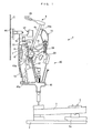
- FIG. 1 shows an upright silent piano 1 according to a first embodiment of the present invention.
- a player's side of the silent piano 1 as viewed from the player (right side as viewed in FIG. 1 ) will be referred to as "front”, and a remote side from the player (left side as viewed in FIG. 1 ) as “rear”.
- a left side of the player will be referred to as “left”, and a right side of the player as "right”.
- the silent piano 1 includes a plurality of (e.g. eighty-eight) keys 3 (only one of which is shown) placed on a keybed 2 in a manner arranged in the left-right direction, actions 40 disposed above the rear parts of the respective keys 3, hammers 4 each provided for an associated one of the keys 3, strings S each stretched at a location rearward of an associated one of the hammers 4, and a pedal device 20 (see FIG. 2 ).
- This silent piano 1 is played while switching the playing mode between an acoustic playing mode (first playing mode) in which playing is performed using acoustic tones generated by striking strings S with respective associated hammers 4 and a silent playing mode (second playing mode) in which playing is performed using electronic tones based on musical tone signals generated by a musical tone generating system 17, described hereinafter.
- first playing mode acoustic playing mode
- second playing mode a silent playing mode
- the key 3 is pivotally supported by a balance rail pin 5 erected on a balance rail 2a on the keybed 2, via a balance rail pin hole (not shown) formed through a central part of the key 3.
- the action 40 is for pivotally moving the hammer 4 in accordance with the key depression and has a wippen 41, a jack 42, and a hammer butt 43 each provided for the associated key 3.
- the wippen 41 and the hammer butt 43 are pivotally supported, respectively, by a wippen flange 41a and a butt flange 43a both mounted to a center rail 10.
- the jack 42 is pivotally mounted to the wippen 41.
- a damper 44 is pivotally mounted to a rear end of the center rail 10.
- the hammer 4 includes a hammer shank 4a extending upward from the hammer butt 43, and a hammer head 4b mounted to an upper end of the hammer shank 4a.
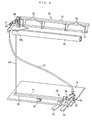
- the pedal device 20 includes a soft pedal 23, a muffler pedal 24, and the damper pedal 25 (see FIG. 3 ) arranged from left to right in the mentioned order and each extending in the front-rear direction, a pedal lever 26 for the soft pedal 23, a pedal lever (not shown) for the damper pedal 25, and a muffler cable 27, and so forth.
- Each of the three pedals 23 to 25 has a rear part thereof mounted on a bottom board 9 via a pedal bracket 9a such that the pedal can perform a vertical pivotal motion.
- the muffler pedal 24 is mounted further in a manner slidable in the left-right direction.
- each of the three pedals 23 to 25 projects forward through a pedal hole 14 formed in a toe rail 13.
- the pedal holes 14 for the soft pedal 23 and the damper pedal 25 are formed into a rectangular shape.
- the pedal hole 14 for the muffler pedal 24 has an engaging part 14a extending leftward from a lower half of the rectangular part. This construction makes it possible to slide the muffler pedal 24 leftward, after step-on of the same, into engagement with the engaging part 14a to thereby hold the muffler pedal 24 in a stepped-on state.
- the pedal lever 26 for the soft pedal 23 has its central part supported by a pedal lever bracket 28 such that the pedal lever 26 can swing.
- the right end of the pedal lever 26 is connected to the soft pedal 23, and the left end thereof is connected to a pedal rod 29.
- the pedal rod 29 is formed by a round bar, and extends upward from the pedal lever 26 to a location close to the left end of a hammer rest rail 15.
- the upper end of the pedal rod 29 is formed as a spring mounting part 29a smaller in diameter than the other part of the pedal rod 29.
- the spring mounting part 29a extends through a hole formed in a bottom wall of the hollow hammer rest rail 15 and projects into the hollow inside of the hollow hammer rest rail 15.
- a coil spring 30 having a predetermined spring force and a predetermined length is mounted on the spring mounting part 29a in a manner held in contact from below with a spring receiving part 18 provided on the bottom wall of the hammer rest rail 15.
- the hammer rest rail 15 is formed by an extrusion molded article made e.g. of an aluminum alloy, and extends in the left-right direction between brackets 12 (only one of which is shown) mounted on the respective left and right ends of the keybed 2 (see FIG. 2 ). As shown in FIGS. 1 and 4 , the hammer rest rail 15 has a hollow sector shape in cross section, and a shock absorbing member 15a formed e.g. of felt is affixed to the rear surface of the hammer rest rail 15 except a left end of the same.
- Front ends of respective arms 16 are fixed to the respective left and right end of the hammer rest rail 15 with screws, and the rear end of each of the arms 16 is engaged with an engaging hole 12c formed in the bracket 12.
- the hammer rest rail 15 is supported by the bracket 12 via the arms 16 in a manner pivotally movable about a horizontal axis.
- the hammer rest rail 15 is held in a stop position (indicated by solid lines in FIG. 7 ) and placed on a rail placing part 12a of the bracket 12 via a shock absorbing member 12b. Further, in a key-off state, the hammer shank 4a of the hammer 4 is in an inclined position in abutment with the hammer rest rail 15 via the shock absorbing member 15a, and hence the key-off position of the hammer 4 is determined according to the position of the hammer rest rail 15.
- the muffler pedal 24 is stepped on to switch the playing mode between the acoustic playing mode and the silent playing mode.
- the muffler pedal 24 is connected to a muffler 50 via the muffler cable 27.
- the muffler 50 is comprised of a drive rod 51, a stop rail 52 for stopping the pivotal motion of the hammer 4, four connecting members 53 for connecting between the drive rod 51 and the stop rail 52, and a drive lever 54 for driving the drive rod 51.
- the drive rod 51 is formed by a round bar.
- the drive rod 51 extends along the whole length of the action 40 in the left-right direction at a location rearward of the bracket 12, and is pivotally supported by the bracket 12 via a support metal fitting 12d (see FIG. 7 ) fixed to the bracket 12. Further, the drive lever 54 is fixed to the drive rod 51 and is connected to the muffler cable 27.
- Each of the connecting members 53 extends in the vertical direction, with a lower end thereof fixed to the drive rod 51 and an upper end thereof fixed to the stop rail 52.
- the stop rail 52 extends in the left-right direction along the whole length of the array of all the hammers 4.
- the stop rail 52 in a state where the muffler pedal 24 is not stepped on, the stop rail 52 is held in a retreated position (indicated by solid lines in FIG. 4 ) where the stop rail 52 is retreated from the range of pivotal motion of the hammer shank 4a of the hammer 4.
- the drive lever 54 and the drive rod 51 integral with the drive lever 54 pivotally move through a predetermined angle in a clockwise direction as viewed in FIG. 4 , whereby the stop rail 52 pivotally moves to an advanced position (indicated by two-dot chain lines in FIG. 4 ) within the range of pivotal motion of the hammer shank 4a.
- a stopper 60 is provided in the vicinity of the left end of the hammer rest rail 15.
- the stopper 60 is configured to prevent the hammer rest rail 15 from being moved by push-up of the pedal rod 29 in the silent playing mode.
- the stopper is comprised of a base part 62, a main stopper 63, and a sub-stopper 64. These parts are each formed e.g. by a bent steel plate, and have the same width.
- the base part 62 has a front wall 62a and left and right side walls 62b and 62b forming a U shape open rearward, and extends vertically.
- the side walls 62b and 62b have lower portions thereof formed with semicircular cutouts 62c and 62c (only one of which is shown), respectively, such that the semicircular cutouts 62c and 62c are opposed to each other.
- the base part 62 is fixed to the drive rod 51 by screwing a countersunk screw 65 into the drive rod 51 via the front wall 62a with the cutouts 62c and 62c fitted on a circumferentially half of part of the drive rod 51.
- the head of the countersunk screw 65 is accommodated in a counterbored hole 62d formed in the front wall 62a so as not to hinder mounting of the main stopper 63 to the front wall 62a.
- the main stopper 63 has an L shape in cross section, and is comprised of a mounting part 63a mounted on the front wall 62a of the base part 62, and a contact part 63b extending forward from the upper end of the mounting part 63a to a location over the hammer rest rail 15 or its vicinity.
- the mounting part 63a is formed with a slot 63c extending in the vertical direction
- the contact part 63b is formed with a slot 63d extending in the front-rear direction.
- the main stopper 63 is fixed to the base part 62 by screwing two screws 66 and 66 passed through the slot 63c into respective two upper and lower screw holes 62e and 62e formed in the front wall 62a.
- the slot 63c of the main stopper 63, the two screw holes 62e and 62e of the base part 62, and the screws 66 and 66 constitute a vertical adjustment mechanism 71.
- the sub-stopper 64 is a flat-plate member attached on the lower surface of the contact part 63b of the main stopper 63. Specifically, the sub-stopper 64 is fixed to the main stopper 63 by screwing two screws 67 and 67 passed through the slot 63d of the contact part 63b into respective two front and rear screw holes 64a and 64a formed in the sub-stopper 64.
- the slot 63d of the main stopper 63, the two screw holes 64a and 64a of the sub-stopper 64, and the screws 67 and 67 constitute a front-rear adjustment mechanism 72.
- a shock absorbing member 15b formed of e.g. a thin sheet-like felt is affixed to a portion of the hammer rest rail 15 corresponding to the stopper 60 (see FIGS. 1 and 4 ).
- the stopper 60 in a state where the muffler pedal 24 is not stepped on, the stopper 60 is held in a permitting position appearing in FIG. 7 .
- the contact part 63b of the main stopper 63 and the sub-stopper 64 are retreated to a location far above the hammer rest rail 15.
- the hammer rest rail 15 is permitted to be moved by the push-up of the pedal rod 19, and moves to the operated position indicated by the two-dot chain lines.
- the stopper 60 is driven by the muffler cable 27, the drive lever 54, and the drive rod 51. That is, in the present embodiment, the four elements 24, 27, 54, and 51 constitute a stopper drive mechanism 61.
- a soft pedal switch 33 is provided in the vicinity of the pedal lever 26, and a muffler pedal switch 34 is provided in the vicinity of the muffler pedal 24 (see FIG. 9 ).
- the switches 33 and 34 are implemented e.g. by microswitches, and output to the musical tone generating system 17 ON/OFF signals corresponding to whether or not the soft pedal 23 and the muffler pedal 24 have been stepped on, respectively.
- the damper pedal 25 is provided with a damper pedal sensor 35 (see FIG. 9 ). The damper pedal sensor 35 outputs a detection signal indicative of a stepped-on amount of the damper pedal 25 to the musical tone generating system 17.
- the musical tone generating system 17 is configured to generate electronic musical tones in the silent playing mode, and is comprised of a shutter 6 and first and second optical sensors 7 and 8 for detecting key depression information on each key 3, a musical tone generating section 17a, a speaker 17b, and a headphone 17c.
- the shutter 6 is formed into a rectangular plate shape, and is fixed to the rear surface of the hammer shank 4a of the hammer 4 in a manner extending rearward.
- the first and second optical sensors 7 and 8 are disposed at respective predetermined locations rearward of the shutter 6.
- Each of the first and second optical sensors 7 and 8 is implemented by a pair of a light emitting diode and a phototransistor (neither of which is shown), and is electrically connected to a printed circuit board 11.
- the first and second optical sensors 7 and 8 are arranged in parallel in the front-rear direction along a turning path of the shutter 6. When the optical paths of the respective optical sensors 7 and 8 are blocked by the shutter 6, the optical sensors 7 and 8 output respective signals of L level as detection signals to the musical tone generating section 17a, whereas when the optical paths are open, the optical sensors 7 and 8 output respective signals of H level as the detection signals to the musical tone generating section 17a.
- the printed circuit board 11 is mounted on a mounting rail (not shown) extending between the left and right brackets 12 and 12.
- the musical tone generating section 17a When the ON signal is being output from the muffler pedal switch 34, i.e. when the muffler pedal 24 is currently stepped on, the musical tone generating section 17a generates a musical tone signal according to the detection signals from the respective first and second optical sensors 7 and 8. Specifically, sounding timing, sounding stop timing, and a tone volume are determined according to the detection signals from the respective first and second optical sensors 7 and 8, and then a musical tone is generated based on the results of the determination, followed by being output to the speaker 17b or the headphone 17c. It should be noted that the musical tone is output to the headphone 17c when a jack (not shown) of the headphone 17c is plugged in.
- the musical tone generating section 17a reduces the level of a tone signal to thereby give a soft pedal effect to an electronic tone. Furthermore, the musical tone generating section 17a adds a predetermined reverberation effect to a musical tone signal according to the detection signal from the damper pedal sensor 35 to thereby give a damper pedal effect to an electronic tone.
- the muffler pedal 24 is held in a non-stepped-on state.
- the stop rail 52 is held in the retreated position (indicated by the solid lines in FIG. 4 ), and the stopper 60 is held in the permitting position (see the position in FIG. 7 ).
- the jack 42 moves upward along with the wippen 41 pivotally moving in accordance with the key depression, to push up the hammer butt 43, whereby the hammer 4 pivotally moves counterclockwise as viewed in FIG. 1 .
- the stop rail 52 since the stop rail 52 is held in the retreated position, the hammer 4 pivotally moves without hindrance by the stop rail 52, and the hammer head 4b strikes the string S, whereby acoustic playing is performed.
- the muffler pedal 24 is stepped on to be brought into engagement with the engaging part 14a.
- the stop rail 52 is moved to the advanced position (indicated by the two-dot chain lines in FIG. 4 ) by the operation described hereinbefore, and the stopper 60 is moved to the blocking position (see the position in FIG. 8 ).
- the key 3 is depressed in this state, the hammer shank 4a of the pivotally moving hammer 4 comes into contact with the stop rail 52 in the advanced position, whereby further pivotal motion of the hammer 4 is prevented so as to prevent the hammer 4 from striking the string S.
- an electronic tone corresponding to a rotational position of the hammer 4 detected by the first and second optical sensors 7 and 8 is generated by the musical tone generating section 17a and output from the speaker 17b or the headphone 17c.
- the stopper 60 is mechanically driven by the stopper drive mechanism 61 in accordance with the operation of the muffler pedal 24 for switching the playing mode, it is possible to reliably and easily drive the stopper 60 for switching the playing mode, without using a sensor or the like.
- the component elements of the stopper drive mechanism 61 i.e. the muffler pedal 24, the muffler cable 27, the drive lever 54, and the drive rod 51 are also used as a drive mechanism for the stop rail 52 that switches the playing mode, and the shared use of the component elements contributes to reduction of the number of components and manufacturing costs.
- the main stopper 63 and the sub-stopper 64 are held in abutment with the hammer rest rail 15, from above and from behind, respectively, at the same time, so that it is possible to reliably hold the hammer rest rail 15 urged by pressure of the pedal rod 29 from performing pivotal motion. Further, since the main stopper 63 and the sub-stopper 64 are screwed via the respective slots 63c and 63d, it is possible to perform continuous adjustment of the main stopper 63 in the vertical direction and continuous adjustment of the sub-stopper 64 in the front-rear direction, independently of each other.
- the present invention is by no means limited to the above-described embodiment, but can be practiced in various forms.
- the stopper drive mechanism 61 for driving the stopper 60 is formed by the muffler pedal 24, the drive rod 51, and so forth, and is shared for use as the drive mechanism for the stop rail 52, the construction may be arbitrarily modified insofar as the stopper 60 can be properly driven in accordance with switching of the playing mode.
- the stopper 60 has the main stopper 63 and the sub-stopper 64 formed as separate members, they may be formed as one piece. Alternatively, it is also within the scope of the present invention that the stopper is more simplified such that it comes into abutment with the hammer rest rail 15 only from above or from behind. Further, it is a matter of course that the slots and the screws used to form the vertical adjustment mechanism and the front-rear adjustment mechanism for adjusting the mounting position of the stopper 60 in the vertical direction and in the front-rear direction, respectively, can be replaced by other suitable means. Further, although the coil spring is used as a spring interposed between the hammer rest rail and the pedal rod, another kind of spring, such as a leaf spring, may be employed.
- the present invention is applied to a silent piano by way of example, this is not limitative, but the present invention can be applied to an automatic playing piano.
- the key-off position of the hammer can be held in the same position as it is in the non-stepped-on state of the soft pedal, and therefore it is possible to obtain appropriate performance data according to a detected rotational position of the hammer.
Landscapes
- Physics & Mathematics (AREA)
- Engineering & Computer Science (AREA)
- Acoustics & Sound (AREA)
- Multimedia (AREA)
- Electrophonic Musical Instruments (AREA)
Abstract
The upright piano comprises sensors (7 and 8) for detecting the rotational position of a hammer 4 in the second playing mode, a hammer rest rail (15) with which the hammer (4) is in contact in a key-off state of a key, a soft pedal (23), a pedal rod (29) for pushing up the hammer rest rail (15) as the soft pedal (23) is stepped on, to cause the same to pivotally move toward a string (S), a spring (30) interposed between the pedal rod (29) and the hammer rest rail (15), a stopper (60) movable between a permitting position for permitting motion of the hammer rest rail (15) caused by the pedal rod (29) and a blocking position for blocking the motion of the hammer rest rail (15) by abutment with the hammer rest rail (15), and a stopper drive mechanism (61) for driving the stopper (60) to the permitting position in the first playing mode and to the blocking position in the second playing mode.
Description
- The present invention relates to an upright piano which is played while switching a plying mode between a first playing mode in which acoustic playing is performed by striking strings with hammers and a second playing mode in which playing is performed while detecting the rotational position of each hammer.
- Conventionally, an upright piano of the above-mentioned type has been disclosed e.g. in Patent Literature 1. This upright piano is a silent piano which is played while switching between a normal playing mode in which playing is performed using acoustic tones and a silent playing mode in which playing is performed using electronic tones. The silent piano includes keys, hammers each of which pivotally moves in accordance with depression of an associated key, a first shutter provided for each key, a first optical sensor disposed below the first shutter, a second shutter provided for each hammer, and second and third optical sensors disposed at a location close to the turning path of the second shutter, and so forth. The first to third sensors are connected to a musical tone generator.
- In the silent playing mode, as the hammer pivotally moves in accordance with key depression, the first shutter blocks the optical path of the first optical sensor, and the second shutter blocks the optical paths of the respective second and third optical sensors, whereby detection signals corresponding to the operations of the respective shutters are output from the respective first to third optical sensors to the musical tone generator. The musical tone generator sets sounding timing and a tone volume based on the detection signals from the second and third optical sensors, and sounding stop timing based on the detection signal from the first optical sensor, and generates a musical tone based on these set control parameters.
- Further, in general, an upright silent piano is provided with a soft pedal for giving a soft pedal effect in the normal playing mode though it is not described in Patent Literature 1. The soft pedal is connected to a pivotally movable hammer rest rail via a pedal lever and a pedal rod, and in a key-off state of a key, the hammers are held in contact with the hammer rest rail. When the soft pedal is stepped on, the hammer rest rail is pushed up and pivotally moves toward the strings, whereby the position of each hammer in the key-off state (hereinafter referred to as "the key-off position of the hammers") approaches the associated string. As a consequence, the distance between the key-off position of the hammer and the string (hereinafter referred to as "the hammer stroke") becomes shorter, whereby the soft pedal effect can be obtained in the normal playing mode.
- In the conventional silent piano constructed as above, when the soft pedal is stepped on in the silent playing mode, the motion of the hammer rest rail caused by the step-on of the soft pedal causes the key-off position of the hammer, i.e. the initial position of the hammer that pivotally moves in accordance with key depression, to approach the string, and hence timing in which the second shutter provided for the hammer blocks the optical paths of the respective second and third optical sensors differs from original blocking timing in a non-stepped-on state of the soft pedal. This makes it impossible to appropriately set sounding timing and a tone volume based on detected blocking timing, and therefore, there is a fear that silent playing cannot be properly performed.
- The present invention has been made in order to solve the above problem, and an object thereof is to provide an upright piano which is capable of providing a soft pedal effect by step-on of a soft pedal in a first playing mode for performing acoustic playing, and an excellent performance in a second playing mode even when the soft pedal is stepped on, without being affected by the step-on of the soft pedal, while properly detecting the rotational position of each hammer.
- [Patent Literature 1] Japanese Laid-Open Patent Publication (Kokai) No.
2007-79312 - To attain the above object, the invention as claimed in claim 1 is an upright piano that is played while switching a playing mode between a first playing mode in which acoustic playing is performed by striking a string using a hammer which pivotally moves in accordance with depression of a key, and a second playing mode in which playing is performed while detecting a rotational position of the hammer, characterized by comprising a sensor disposed at a location close to a turning path of the hammer, for detecting a rotational position of the hammer in the second playing mode, a hammer rest rail which is pivotally movable and with which the hammer is in contact in a key-off state of the key, a soft pedal which is stepped on so as to give a soft pedal effect, a pedal rod having a lower end thereof connected to the soft pedal, for being moved upward as the soft pedal is stepped on, to thereby push up the hammer rest rail to cause the hammer to pivotally move toward the string, a spring interposed between the pedal rod and the hammer rest rail, a stopper movable between a permitting position in which the stopper is retreated from the hammer rest rail to permit motion of the hammer rest rail caused by pushing-up of the pedal rod and a blocking position in which the stopper is in abutment with the hammer rest rail to prevent the motion of the hammer rest rail, and a stopper drive mechanism that drives the stopper to the permitting position in the first playing mode and to the blocking position in the second playing mode.
- According to this upright piano, the hammer is in contact with the hammer rest rail in the key-off state of the key, and when the key is depressed, the hammer pivotally moves in accordance with the key depression to strike the string. In the first playing mode for performing acoustic playing, the stopper is in the permitting position to be kept retreated from the hammer rest rail by the drive of the stopper drive mechanism. When the soft pedal is stepped on in this state, the pedal rod moves upward in accordance with the step-on of the soft pedal to push up the hammer rest rail via the spring. In this case, since the stopper is in the permitting position, the hammer rest rail pivotally moves toward the string without hindrance by the stopper. This causes the key-off position of the hammer to approach the string, whereby the soft pedal effect is provided.
- On the other hand, in the second playing mode, playing is performed while detecting the rotational position of the hammer by the sensor disposed at the location close to the turning path of the hammer. Further, in the second playing mode, the stopper is in the blocking position by the drive of the stopper drive mechanism and is in abutment with the hammer rest rail. When the soft pedal is stepped on in this state, the pedal rod moves upward to urge the hammer rest rail. However, since the stopper in the blocking position is in abutment with the hammer rest rail, only deformation of the spring interposed between the pedal rod and the hammer rest rail occurs, and the pivotal motion of the hammer rest rail is prevented. As a consequence, the key-off position of the hammer is held in the same position as it is in the non-stepped-on state of the soft pedal, so that the relationship between a key depression stroke of the key and the rotational position of the hammer in the stepped-on state of the soft pedal is held unchanged from that in the non-stepped-on state of the soft pedal. Therefore, even when the soft pedal is stepped on in the second playing mode, it is possible to perform excellent playing, without being affected by the step-on of the soft pedal, while properly detecting the rotational position of the hammer corresponding to the key depression stroke by the sensor.
- The invention as claimed in
claim 2 is an upright piano as claimed in claim 1, wherein the stopper drive mechanism comprises a switching pedal operated to switch the playing mode between the first playing mode and the second playing mode, and a drive member that operates in accordance with the operation of the switch pedal, to drive the stopper to the permitting position or to the blocking position. - With this construction, the playing mode is switched between the first playing mode and the second playing mode by operating the switching pedal, and the drive member moves in accordance with the operation of the switching pedal to drive the stopper to the permitting position or to the blocking position. Thus, the drive member moves mechanically in accordance with the operation of the switching pedal for switching the playing mode, to drive the stopper to the permitting position or to the blocking position, which makes it possible to reliably and easily drive the stopper for switching the playing mode, without using a sensor or the like
- The invention as claimed in
claim 3 is an upright piano as claimed inclaim 1 or 2, wherein the stopper comprises a main stopper part for abutment with the hammer rest rail from above in the blocking position, and a sub-stopper part for abutment with the hammer rest rail from behind in the blocking position. - With this construction, when the stopper is in the blocking position, not only is the main stopper part of the stopper is in abutment with the hammer rest rail from above, but also the sub-stopper part in abutment with the hammer rest rail from behind. Thus, the hammer rest rail is held by the main stopper part and the sub-stopper part from above and behind, respectively, at the same time, which makes it possible to reliably hold the hammer rest rail urged by pressure of the pedal rod from performing pivotal motion.
- The invention as claimed in
claim 4 is an upright piano as claimed inclaim 3, wherein the main stopper part and the sub-stopper part are formed as separate members, and wherein the stopper comprises a vertical adjustment mechanism for adjusting a mounting position of the main stopper part in a vertical direction, and a front-rear adjustment mechanism for adjusting a mounting position of the sub-stopper part in a front-rear direction. - With this construction, the vertical adjustment mechanism adjusts the mounting position of the main stopper part in the vertical direction, and the front-rear adjustment mechanism adjusts the mounting position of the sub-stopper part in the front-rear direction. Therefore, even when the main stopper part and the sub-stopper part deviate from the proper positional relationship with the hammer rest rail due to manufacturing errors or mounting errors of components, it is possible to easily adjust the mounting positions of the main stopper part and the sub-stopper part so as to accommodate the deviation and cause the two stopper parts to be brought into abutment with the hammer rest rail in an optimal state.
- The invention as claimed in
claim 5 is an upright piano as claimed in any one of claims 1 to 4, wherein the second playing mode is a silent playing mode in which silent playing is performed using an electronic tone based on a musical tone signal generated according to the rotational position of the hammer detected by the sensor. - With this configuration, even when the soft pedal is stepped on in the silent playing mode, it is possible to correctly detect a rotational position of the hammer corresponding to the key depression stroke. This makes it possible to perform excellent silent playing while appropriately setting sounding timing and sounding stop timing for a musical tone and the tone volume of the musical tone according to the detected rotational position.
- The invention will now be described in detail with reference to the drawings showing a preferred embodiment thereof.
FIG. 1 shows an upright silent piano 1 according to a first embodiment of the present invention. It should be noted that in the following description, a player's side of the silent piano 1 as viewed from the player (right side as viewed inFIG. 1 ) will be referred to as "front", and a remote side from the player (left side as viewed inFIG. 1 ) as "rear". Further, a left side of the player will be referred to as "left", and a right side of the player as "right". - As shown in
FIG. 1 , the silent piano 1 includes a plurality of (e.g. eighty-eight) keys 3 (only one of which is shown) placed on akeybed 2 in a manner arranged in the left-right direction,actions 40 disposed above the rear parts of therespective keys 3,hammers 4 each provided for an associated one of thekeys 3, strings S each stretched at a location rearward of an associated one of thehammers 4, and a pedal device 20 (seeFIG. 2 ). This silent piano 1 is played while switching the playing mode between an acoustic playing mode (first playing mode) in which playing is performed using acoustic tones generated by striking strings S with respective associatedhammers 4 and a silent playing mode (second playing mode) in which playing is performed using electronic tones based on musical tone signals generated by a musicaltone generating system 17, described hereinafter. - The
key 3 is pivotally supported by abalance rail pin 5 erected on a balance rail 2a on thekeybed 2, via a balance rail pin hole (not shown) formed through a central part of thekey 3. - The
action 40 is for pivotally moving thehammer 4 in accordance with the key depression and has awippen 41, ajack 42, and ahammer butt 43 each provided for the associatedkey 3. Thewippen 41 and thehammer butt 43 are pivotally supported, respectively, by awippen flange 41a and abutt flange 43a both mounted to acenter rail 10. Thejack 42 is pivotally mounted to thewippen 41. Further, adamper 44 is pivotally mounted to a rear end of thecenter rail 10. When thekey 3 is released after key depression in a state where adamper pedal 25, described hereinafter, is not operated, thedamper 44 comes into contact with the string S to thereby stop sounding. - On the other hand, the
hammer 4 includes ahammer shank 4a extending upward from thehammer butt 43, and ahammer head 4b mounted to an upper end of thehammer shank 4a. - As shown in
FIG. 2 , thepedal device 20 includes asoft pedal 23, amuffler pedal 24, and the damper pedal 25 (seeFIG. 3 ) arranged from left to right in the mentioned order and each extending in the front-rear direction, apedal lever 26 for thesoft pedal 23, a pedal lever (not shown) for thedamper pedal 25, and amuffler cable 27, and so forth. - Each of the three
pedals 23 to 25 has a rear part thereof mounted on abottom board 9 via apedal bracket 9a such that the pedal can perform a vertical pivotal motion. Themuffler pedal 24 is mounted further in a manner slidable in the left-right direction. As shown inFIG. 3 , each of the threepedals 23 to 25 projects forward through apedal hole 14 formed in atoe rail 13. Thepedal holes 14 for thesoft pedal 23 and thedamper pedal 25 are formed into a rectangular shape. On the other hand, thepedal hole 14 for themuffler pedal 24 has anengaging part 14a extending leftward from a lower half of the rectangular part. This construction makes it possible to slide themuffler pedal 24 leftward, after step-on of the same, into engagement with theengaging part 14a to thereby hold themuffler pedal 24 in a stepped-on state. - The
pedal lever 26 for thesoft pedal 23 has its central part supported by apedal lever bracket 28 such that thepedal lever 26 can swing. The right end of thepedal lever 26 is connected to thesoft pedal 23, and the left end thereof is connected to apedal rod 29. - The
pedal rod 29 is formed by a round bar, and extends upward from thepedal lever 26 to a location close to the left end of ahammer rest rail 15. As shown inFIG. 4 , the upper end of thepedal rod 29 is formed as aspring mounting part 29a smaller in diameter than the other part of thepedal rod 29. Thespring mounting part 29a extends through a hole formed in a bottom wall of the hollowhammer rest rail 15 and projects into the hollow inside of the hollowhammer rest rail 15. Further, acoil spring 30 having a predetermined spring force and a predetermined length is mounted on thespring mounting part 29a in a manner held in contact from below with aspring receiving part 18 provided on the bottom wall of thehammer rest rail 15. - The
hammer rest rail 15 is formed by an extrusion molded article made e.g. of an aluminum alloy, and extends in the left-right direction between brackets 12 (only one of which is shown) mounted on the respective left and right ends of the keybed 2 (seeFIG. 2 ). As shown inFIGS. 1 and4 , thehammer rest rail 15 has a hollow sector shape in cross section, and ashock absorbing member 15a formed e.g. of felt is affixed to the rear surface of thehammer rest rail 15 except a left end of the same. - Front ends of respective arms 16 (only one of which is shown) are fixed to the respective left and right end of the
hammer rest rail 15 with screws, and the rear end of each of thearms 16 is engaged with an engaginghole 12c formed in thebracket 12. Thus, thehammer rest rail 15 is supported by thebracket 12 via thearms 16 in a manner pivotally movable about a horizontal axis. - With the above-described construction, in a state where the
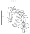
soft pedal 23 is not stepped on, thehammer rest rail 15 is held in a stop position (indicated by solid lines inFIG. 7 ) and placed on arail placing part 12a of thebracket 12 via ashock absorbing member 12b. Further, in a key-off state, thehammer shank 4a of thehammer 4 is in an inclined position in abutment with thehammer rest rail 15 via theshock absorbing member 15a, and hence the key-off position of thehammer 4 is determined according to the position of thehammer rest rail 15. - On the other hand, when the
soft pedal 23 is stepped on, a portion of thepedal lever 26 rightward of thepedal lever bracket 28 is pulled down, and a left portion of thepedal lever 26 pivotally moves upward, whereby thepedal rod 29 moves upward to push up thehammer rest rail 15 via thecoil spring 30. As a consequence, thehammer rest rail 15 pivotally moves rearward from the stop position through a predetermined angle to an operated position (indicated by two-dot chain lines inFIG. 7 ), and the key-off position of thehammer 4 also moves toward the string S in accordance with the motion of the hammer rest rail 15 (see a position indicated by two-dot chain lines inFIG. 7 ). - The
muffler pedal 24 is stepped on to switch the playing mode between the acoustic playing mode and the silent playing mode. Themuffler pedal 24 is connected to amuffler 50 via themuffler cable 27. As shown inFIG. 2 , themuffler 50 is comprised of adrive rod 51, astop rail 52 for stopping the pivotal motion of thehammer 4, four connectingmembers 53 for connecting between thedrive rod 51 and thestop rail 52, and adrive lever 54 for driving thedrive rod 51. - The
drive rod 51 is formed by a round bar. Thedrive rod 51 extends along the whole length of theaction 40 in the left-right direction at a location rearward of thebracket 12, and is pivotally supported by thebracket 12 via a support metal fitting 12d (seeFIG. 7 ) fixed to thebracket 12. Further, thedrive lever 54 is fixed to thedrive rod 51 and is connected to themuffler cable 27. - Each of the connecting
members 53 extends in the vertical direction, with a lower end thereof fixed to thedrive rod 51 and an upper end thereof fixed to thestop rail 52. Thestop rail 52 extends in the left-right direction along the whole length of the array of all thehammers 4. - With the above-described arrangement, in a state where the
muffler pedal 24 is not stepped on, thestop rail 52 is held in a retreated position (indicated by solid lines inFIG. 4 ) where thestop rail 52 is retreated from the range of pivotal motion of thehammer shank 4a of thehammer 4. On the other hand, when themuffler pedal 24 is stepped on, as themuffler cable 27 is pulled down, thedrive lever 54 and thedrive rod 51 integral with thedrive lever 54 pivotally move through a predetermined angle in a clockwise direction as viewed inFIG. 4 , whereby thestop rail 52 pivotally moves to an advanced position (indicated by two-dot chain lines inFIG. 4 ) within the range of pivotal motion of thehammer shank 4a. - As shown in
FIG. 2 , astopper 60 is provided in the vicinity of the left end of thehammer rest rail 15. Thestopper 60 is configured to prevent thehammer rest rail 15 from being moved by push-up of thepedal rod 29 in the silent playing mode. As shown inFIGS. 5 and 6 , the stopper is comprised of abase part 62, amain stopper 63, and a sub-stopper 64. These parts are each formed e.g. by a bent steel plate, and have the same width. - The
base part 62 has afront wall 62a and left andright side walls side walls semicircular cutouts semicircular cutouts base part 62 is fixed to thedrive rod 51 by screwing a countersunkscrew 65 into thedrive rod 51 via thefront wall 62a with thecutouts drive rod 51. The head of the countersunkscrew 65 is accommodated in acounterbored hole 62d formed in thefront wall 62a so as not to hinder mounting of themain stopper 63 to thefront wall 62a. - The
main stopper 63 has an L shape in cross section, and is comprised of a mountingpart 63a mounted on thefront wall 62a of thebase part 62, and acontact part 63b extending forward from the upper end of the mountingpart 63a to a location over thehammer rest rail 15 or its vicinity. The mountingpart 63a is formed with aslot 63c extending in the vertical direction, and thecontact part 63b is formed with aslot 63d extending in the front-rear direction. Themain stopper 63 is fixed to thebase part 62 by screwing twoscrews slot 63c into respective two upper andlower screw holes front wall 62a. - With the above-described construction, by sliding the
main stopper 63 vertically on thefront wall 62a along theslot 63c before screwing thescrews 66, it is possible to continuously adjust the mounting position of themain stopper 63 vertically. That is, in the present embodiment, theslot 63c of themain stopper 63, the twoscrew holes base part 62, and thescrews vertical adjustment mechanism 71. - The sub-stopper 64 is a flat-plate member attached on the lower surface of the
contact part 63b of themain stopper 63. Specifically, the sub-stopper 64 is fixed to themain stopper 63 by screwing twoscrews slot 63d of thecontact part 63b into respective two front andrear screw holes - With the above-described construction, by sliding the sub-stopper 64 on the
contact part 63b in the front-rear direction along theslot 63d before screwing thescrews 67, it is possible to continuously adjust the mounting position of the sub-stopper 64 in the front-rear direction. That is, in the present embodiment, theslot 63d of themain stopper 63, the twoscrew holes screws rear adjustment mechanism 72. - Further, a
shock absorbing member 15b formed of e.g. a thin sheet-like felt is affixed to a portion of thehammer rest rail 15 corresponding to the stopper 60 (seeFIGS. 1 and4 ). - With the above-described construction, in a state where the
muffler pedal 24 is not stepped on, thestopper 60 is held in a permitting position appearing inFIG. 7 . In this permitting position, thecontact part 63b of themain stopper 63 and the sub-stopper 64 are retreated to a location far above thehammer rest rail 15. As a consequence, when thesoft pedal 23 is stepped on, thehammer rest rail 15 is permitted to be moved by the push-up of the pedal rod 19, and moves to the operated position indicated by the two-dot chain lines. - On the other hand, when the
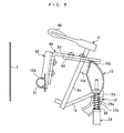
muffler pedal 24 is stepped on, as thedrive rod 51 is pivotally moved by themuffler cable 27 and thedrive lever 54, thestopper 60 integral with thedrive rod 51 pivotally moves from the permitting position through the predetermined angle in the clockwise direction, whereby thestopper 60 moves to a blocking position shown inFIG. 8 . In this blocking position, thecontact part 63b of themain stopper 63 and the front end of the sub-stopper 64 come into abutment with thehammer rest rail 15, from above and from behind, respectively, via theshock absorbing member 15b at respective portions of thehammer rest rail 15 close to its top part as a boundary between its front and rear surfaces. This blocks the motion of thehammer rest rail 15 caused by the push-up of thepedal rod 29 when thesoft pedal 23 is stepped on, whereby thehammer rest rail 15 is held in the stop position. - As described above, when the
muffler pedal 24 is stepped on, thestopper 60 is driven by themuffler cable 27, thedrive lever 54, and thedrive rod 51. That is, in the present embodiment, the fourelements stopper drive mechanism 61. - Further, a
soft pedal switch 33 is provided in the vicinity of thepedal lever 26, and amuffler pedal switch 34 is provided in the vicinity of the muffler pedal 24 (seeFIG. 9 ). Theswitches tone generating system 17 ON/OFF signals corresponding to whether or not thesoft pedal 23 and themuffler pedal 24 have been stepped on, respectively. Further, thedamper pedal 25 is provided with a damper pedal sensor 35 (seeFIG. 9 ). Thedamper pedal sensor 35 outputs a detection signal indicative of a stepped-on amount of thedamper pedal 25 to the musicaltone generating system 17. - The musical
tone generating system 17 is configured to generate electronic musical tones in the silent playing mode, and is comprised of ashutter 6 and first and secondoptical sensors tone generating section 17a, aspeaker 17b, and aheadphone 17c. - As shown in
FIG. 4 , theshutter 6 is formed into a rectangular plate shape, and is fixed to the rear surface of thehammer shank 4a of thehammer 4 in a manner extending rearward. The first and secondoptical sensors shutter 6. - Each of the first and second
optical sensors circuit board 11. The first and secondoptical sensors shutter 6. When the optical paths of the respectiveoptical sensors shutter 6, theoptical sensors tone generating section 17a, whereas when the optical paths are open, theoptical sensors tone generating section 17a. The printedcircuit board 11 is mounted on a mounting rail (not shown) extending between the left andright brackets - When the ON signal is being output from the
muffler pedal switch 34, i.e. when themuffler pedal 24 is currently stepped on, the musicaltone generating section 17a generates a musical tone signal according to the detection signals from the respective first and secondoptical sensors optical sensors speaker 17b or theheadphone 17c. It should be noted that the musical tone is output to theheadphone 17c when a jack (not shown) of theheadphone 17c is plugged in. - Further, when the ON signal is being output from the
soft pedal switch 33, the musicaltone generating section 17a reduces the level of a tone signal to thereby give a soft pedal effect to an electronic tone. Furthermore, the musicaltone generating section 17a adds a predetermined reverberation effect to a musical tone signal according to the detection signal from thedamper pedal sensor 35 to thereby give a damper pedal effect to an electronic tone. - Next, a description will be given of the operation of the silent piano 1 constructed as described above. In the case of carrying out acoustic playing, the
muffler pedal 24 is held in a non-stepped-on state. As described hereinbefore, when themuffler pedal 24 is in the non-stepped-on state, thestop rail 52 is held in the retreated position (indicated by the solid lines inFIG. 4 ), and thestopper 60 is held in the permitting position (see the position inFIG. 7 ). As thekey 3 is depressed in this state, thejack 42 moves upward along with the wippen 41 pivotally moving in accordance with the key depression, to push up thehammer butt 43, whereby thehammer 4 pivotally moves counterclockwise as viewed inFIG. 1 . In this case, since thestop rail 52 is held in the retreated position, thehammer 4 pivotally moves without hindrance by thestop rail 52, and thehammer head 4b strikes the string S, whereby acoustic playing is performed. - When the
soft pedal 23 is stepped on during this acoustic playing, thepedal rod 29 is driven via thepedal lever 26 to move upward, whereby thehammer rest rail 15 is pushed up via thecoil spring 30. In this case, since thestopper 60 is held in the permitting position, thehammer rest rail 15 pivotally moves counterclockwise as viewed inFIG. 7 , without hindrance by thestopper 60, from the stop position (indicated by the solid lines) to the operated position (indicated by the two-dot chain lines). In accordance with this, thehammer 4 as well pivotally moves toward the string S, and the key-off position of thehammer 4 approaches the string S, whereby the soft pedal effect can be obtained. - On the other hand, in the case of carrying out silent playing, the
muffler pedal 24 is stepped on to be brought into engagement with theengaging part 14a. When themuffler pedal 24 is thus stepped on, thestop rail 52 is moved to the advanced position (indicated by the two-dot chain lines inFIG. 4 ) by the operation described hereinbefore, and thestopper 60 is moved to the blocking position (see the position inFIG. 8 ). As thekey 3 is depressed in this state, thehammer shank 4a of the pivotally movinghammer 4 comes into contact with thestop rail 52 in the advanced position, whereby further pivotal motion of thehammer 4 is prevented so as to prevent thehammer 4 from striking the string S. Further, an electronic tone corresponding to a rotational position of thehammer 4 detected by the first and secondoptical sensors tone generating section 17a and output from thespeaker 17b or theheadphone 17c. - When the
soft pedal 23 is stepped on during this silent playing, thepedal rod 29 moves upward, as shown inFIG. 8 , to urge thehammer rest rail 15. However, since thestopper 60 in the blocking position is held in abutment with thehammer rest rail 15, thecoil spring 30 is compressed, but thehammer rest rail 15 is held in the stop position without being pivotally moved. As a consequence, the key-off position of thehammer 4 is also held in the same position as it is in the non-stepped-on state of thesoft pedal 23, so that the relationship between the key depression stroke of thekey 3 and the rotational position of thehammer 4 in the stepped-on state of thesoft pedal 23 is held unchanged from that in the non-stepped-on state of thesoft pedal 23. Therefore, even when thesoft pedal 23 is stepped on during silent playing, it is possible to perform excellent silent playing, without being affected by the step-on of thesoft pedal 23, while properly detecting the rotational position of thehammer 4 corresponding to the key depression stroke of the key 3 by the first and secondoptical sensors - Further, since the
stopper 60 is mechanically driven by thestopper drive mechanism 61 in accordance with the operation of themuffler pedal 24 for switching the playing mode, it is possible to reliably and easily drive thestopper 60 for switching the playing mode, without using a sensor or the like. Furthermore, the component elements of thestopper drive mechanism 61, i.e. themuffler pedal 24, themuffler cable 27, thedrive lever 54, and thedrive rod 51 are also used as a drive mechanism for thestop rail 52 that switches the playing mode, and the shared use of the component elements contributes to reduction of the number of components and manufacturing costs. - When the
stopper 60 is in the blocking position, themain stopper 63 and the sub-stopper 64 are held in abutment with thehammer rest rail 15, from above and from behind, respectively, at the same time, so that it is possible to reliably hold thehammer rest rail 15 urged by pressure of thepedal rod 29 from performing pivotal motion. Further, since themain stopper 63 and the sub-stopper 64 are screwed via therespective slots main stopper 63 in the vertical direction and continuous adjustment of the sub-stopper 64 in the front-rear direction, independently of each other. Therefore, even when themain stopper 63 and the sub-stopper 64 deviate from the proper positional relationship with thehammer rest rail 15 due to manufacturing errors or mounting errors of components, it is possible to easily adjust the mounting positions of the respective twostoppers stoppers hammer rest rail 15 in an optimal state. - It should be noted that the present invention is by no means limited to the above-described embodiment, but can be practiced in various forms. For example, although in the present embodiment, the
stopper drive mechanism 61 for driving thestopper 60 is formed by themuffler pedal 24, thedrive rod 51, and so forth, and is shared for use as the drive mechanism for thestop rail 52, the construction may be arbitrarily modified insofar as thestopper 60 can be properly driven in accordance with switching of the playing mode. - Further, although in the present embodiment, the
stopper 60 has themain stopper 63 and the sub-stopper 64 formed as separate members, they may be formed as one piece. Alternatively, it is also within the scope of the present invention that the stopper is more simplified such that it comes into abutment with thehammer rest rail 15 only from above or from behind. Further, it is a matter of course that the slots and the screws used to form the vertical adjustment mechanism and the front-rear adjustment mechanism for adjusting the mounting position of thestopper 60 in the vertical direction and in the front-rear direction, respectively, can be replaced by other suitable means. Further, although the coil spring is used as a spring interposed between the hammer rest rail and the pedal rod, another kind of spring, such as a leaf spring, may be employed. - Moreover, although in the above-described embodiment, the present invention is applied to a silent piano by way of example, this is not limitative, but the present invention can be applied to an automatic playing piano. In this case, even when the soft pedal is stepped on during recording of performance data, the key-off position of the hammer can be held in the same position as it is in the non-stepped-on state of the soft pedal, and therefore it is possible to obtain appropriate performance data according to a detected rotational position of the hammer. It is to be further understood that various changes and modifications may be made without departing from the spirit and scope thereof.
-
- [
FIG. 1 ]
A schematic side view of an upright silent piano according to an embodiment of the present invention. - [
FIG. 2 ]
A perspective view of a pedal device. - [
FIG. 3 ]
An enlarged partial perspective view of the pedal device. - [
FIG. 4 ]
A side view useful in explaining operation of a stop rail. - [
FIG. 5 ]
A perspective view of a stopper of a hammer rest rail. - [
FIG. 6 ]
A cross-sectional view of the stopper. - [
FIG. 7 ]
A side view useful in explaining an operation in a state where the stopper is held in a permitting position. - [
FIG. 8 ]
A side view useful in explaining an operation in a state where the stopper is held in a blocking position. - [
FIG. 9 ]
A block diagram of a musical tone generating system.
Claims (5)
wherein said stopper comprises:
Applications Claiming Priority (1)
| Application Number | Priority Date | Filing Date | Title |
|---|---|---|---|
| JP2007265867A JP4859806B2 (en) | 2007-10-11 | 2007-10-11 | Upright piano |
Publications (2)
| Publication Number | Publication Date |
|---|---|
| EP2051237A1 true EP2051237A1 (en) | 2009-04-22 |
| EP2051237B1 EP2051237B1 (en) | 2012-05-30 |
Family
ID=40229793
Family Applications (1)
| Application Number | Title | Priority Date | Filing Date |
|---|---|---|---|
| EP08017658A Active EP2051237B1 (en) | 2007-10-11 | 2008-10-08 | Upright piano |
Country Status (4)
| Country | Link |
|---|---|
| US (1) | US7858858B2 (en) |
| EP (1) | EP2051237B1 (en) |
| JP (1) | JP4859806B2 (en) |
| CN (1) | CN101409068B (en) |
Cited By (1)
| Publication number | Priority date | Publication date | Assignee | Title |
|---|---|---|---|---|
| CN108630169A (en) * | 2017-03-16 | 2018-10-09 | 卡西欧计算机株式会社 | Key board unit and keyboard instrument |
Families Citing this family (14)
| Publication number | Priority date | Publication date | Assignee | Title |
|---|---|---|---|---|
| WO2012004999A1 (en) * | 2010-07-08 | 2012-01-12 | 有限会社藤井ピアノサービス | Action for upright piano |
| US8735699B2 (en) * | 2012-01-19 | 2014-05-27 | Kirk Burgett | Main action rail for upright piano with front-accessible whippen flange screw |
| CN103383842B (en) * | 2012-04-02 | 2018-05-29 | 施坦威音乐器材有限公司 | For the hammer retainer with acoustics and the piano of silent mode |
| US9343044B2 (en) | 2013-10-03 | 2016-05-17 | Steinway, Inc. | Piano extended soft pedal |
| US8927835B1 (en) * | 2013-10-03 | 2015-01-06 | Steinway Musical Instruments, Inc. | Piano extended soft pedal |
| US9159302B2 (en) | 2013-10-03 | 2015-10-13 | Steinway Musical Instruments, Inc. | Piano extended soft pedal/CIP |
| WO2016200483A1 (en) * | 2015-06-12 | 2016-12-15 | Steinway, Inc. | Piano extended soft pedal |
| CN105006224A (en) * | 2015-08-14 | 2015-10-28 | 森鹤乐器股份有限公司 | Sound producing wooden grain of piano string striking machine |
| WO2018090798A1 (en) | 2016-11-17 | 2018-05-24 | Sunland Information Technology Co., Ltd. | System and method for recording user performance of keyboard instrument |
| CN107591146A (en) * | 2017-09-07 | 2018-01-16 | 大连佳音科技有限公司 | A kind of piano performance action detection device |
| CN109448667B (en) * | 2018-09-12 | 2021-03-30 | 烟台南山学院 | A piano extended soft pedal |
| CN109658906B (en) * | 2018-12-20 | 2021-12-17 | 宁波迪比亿贸易有限公司 | Multifunctional platform piano |
| CN110047453A (en) * | 2019-04-26 | 2019-07-23 | 南阳理工学院 | It is a kind of for the hammer retainer with acoustics and the piano of silent mode |
| CN117207204B (en) * | 2023-11-09 | 2024-01-30 | 之江实验室 | A control method and control device for a piano-playing robot |
Citations (4)
| Publication number | Priority date | Publication date | Assignee | Title |
|---|---|---|---|---|
| US5200570A (en) | 1989-08-08 | 1993-04-06 | Yamaha Corporation | Key-touch state detection device for an automatic performance piano |
| US5451706A (en) * | 1992-02-14 | 1995-09-19 | Yamaha Corporation | Automatic player piano equipped with mute lock system for reproducing faint sounds in playback mode |
| JP2007079312A (en) | 2005-09-15 | 2007-03-29 | Kawai Musical Instr Mfg Co Ltd | Keyboard instrument touch detection device |
| EP1837853A1 (en) * | 2006-03-20 | 2007-09-26 | Yamaha Corporation | Musical instrument having controller exactly discriminating half-pedal and controlling system used therein |
Family Cites Families (6)
| Publication number | Priority date | Publication date | Assignee | Title |
|---|---|---|---|---|
| US4572911A (en) * | 1984-08-02 | 1986-02-25 | Mcneilab, Inc. | Hexahydroindolinzine compounds, pharmaceutical compositions and methods and intermediates |
| JP3463365B2 (en) * | 1993-11-30 | 2003-11-05 | ヤマハ株式会社 | Keyboard instrument |
| JP3493743B2 (en) * | 1994-09-20 | 2004-02-03 | ヤマハ株式会社 | Keyboard instrument |
| US5539142A (en) * | 1995-06-07 | 1996-07-23 | Baldwin Piano And Organ Company | Combined acoustic and electronic piano in which the acoustic action is disabled when played in the electronic mode |
| JP2005345896A (en) * | 2004-06-04 | 2005-12-15 | Kawai Musical Instr Mfg Co Ltd | Upright piano action |
| JP4650361B2 (en) * | 2006-07-14 | 2011-03-16 | ヤマハ株式会社 | Optical shutter body |
-
2007
- 2007-10-11 JP JP2007265867A patent/JP4859806B2/en active Active
-
2008
- 2008-10-08 EP EP08017658A patent/EP2051237B1/en active Active
- 2008-10-10 US US12/249,381 patent/US7858858B2/en active Active
- 2008-10-13 CN CN2008101799124A patent/CN101409068B/en active Active
Patent Citations (4)
| Publication number | Priority date | Publication date | Assignee | Title |
|---|---|---|---|---|
| US5200570A (en) | 1989-08-08 | 1993-04-06 | Yamaha Corporation | Key-touch state detection device for an automatic performance piano |
| US5451706A (en) * | 1992-02-14 | 1995-09-19 | Yamaha Corporation | Automatic player piano equipped with mute lock system for reproducing faint sounds in playback mode |
| JP2007079312A (en) | 2005-09-15 | 2007-03-29 | Kawai Musical Instr Mfg Co Ltd | Keyboard instrument touch detection device |
| EP1837853A1 (en) * | 2006-03-20 | 2007-09-26 | Yamaha Corporation | Musical instrument having controller exactly discriminating half-pedal and controlling system used therein |
Cited By (1)
| Publication number | Priority date | Publication date | Assignee | Title |
|---|---|---|---|---|
| CN108630169A (en) * | 2017-03-16 | 2018-10-09 | 卡西欧计算机株式会社 | Key board unit and keyboard instrument |
Also Published As
| Publication number | Publication date |
|---|---|
| JP2009093087A (en) | 2009-04-30 |
| CN101409068B (en) | 2012-06-27 |
| CN101409068A (en) | 2009-04-15 |
| US7858858B2 (en) | 2010-12-28 |
| US20090100980A1 (en) | 2009-04-23 |
| EP2051237B1 (en) | 2012-05-30 |
| JP4859806B2 (en) | 2012-01-25 |
Similar Documents
| Publication | Publication Date | Title |
|---|---|---|
| EP2051237B1 (en) | Upright piano | |
| CN1818663B (en) | Velocity detection equipment for keyboard instruments | |
| JP3456243B2 (en) | Flat keyboard instruments | |
| US12542118B2 (en) | Keyboard device for keyboard instrument | |
| US6271447B1 (en) | Velocity calculating system for moving object widely varied in velocity method for correcting velocity and keyboard musical instrument equipped with the velocity calculating system for accurately determining loudness of sounds | |
| JPH07219522A (en) | Keyboard musical instrument | |
| KR100412026B1 (en) | Keyboard musical instrument equipped with partially repaireable change-over mechanism for changing hammer stopper | |
| JP3861906B2 (en) | Silencer for keyboard instruments | |
| JP3479397B2 (en) | Musical instrument | |
| JP3693047B2 (en) | Silencer for keyboard instruments | |
| JP3431369B2 (en) | Electronic musical instrument keyboard and electronic piano | |
| JPH0612057A (en) | Keyboard musical instrument | |
| JP3413931B2 (en) | Vertical keyboard instrument | |
| JP3823999B2 (en) | Silencer for keyboard instrument and keyboard instrument | |
| JPH09127945A (en) | Musical tone device | |
| JP2009244307A (en) | Grand piano | |
| JPH07261749A (en) | Keyboard instrument | |
| JP2011112951A (en) | Damper device of grand piano | |
| US20250308495A1 (en) | Musical sound control method for keyboard instrument | |
| US20250308494A1 (en) | Musical sound control device for keyboard instrument | |
| US20250308490A1 (en) | Musical sound control method for keyboard instrument | |
| JP3654268B2 (en) | Keyboard instrument | |
| JP6766511B2 (en) | Keyboard instrument | |
| JP3856032B2 (en) | Keyboard instrument | |
| JPH09120289A (en) | Electronic musical instrument keyboard device and electronic piano |
Legal Events
| Date | Code | Title | Description |
|---|---|---|---|
| PUAI | Public reference made under article 153(3) epc to a published international application that has entered the european phase |
Free format text: ORIGINAL CODE: 0009012 |
|
| AK | Designated contracting states |
Kind code of ref document: A1 Designated state(s): AT BE BG CH CY CZ DE DK EE ES FI FR GB GR HR HU IE IS IT LI LT LU LV MC MT NL NO PL PT RO SE SI SK TR |
|
| AX | Request for extension of the european patent |
Extension state: AL BA MK RS |
|
| 17P | Request for examination filed |
Effective date: 20090707 |
|
| 17Q | First examination report despatched |
Effective date: 20090810 |
|
| AKX | Designation fees paid |
Designated state(s): DE GB |
|
| GRAP | Despatch of communication of intention to grant a patent |
Free format text: ORIGINAL CODE: EPIDOSNIGR1 |
|
| GRAS | Grant fee paid |
Free format text: ORIGINAL CODE: EPIDOSNIGR3 |
|
| GRAA | (expected) grant |
Free format text: ORIGINAL CODE: 0009210 |
|
| RIN1 | Information on inventor provided before grant (corrected) |
Inventor name: EITAKI, SHU Inventor name: OKANO, TETSUYA |
|
| AK | Designated contracting states |
Kind code of ref document: B1 Designated state(s): DE GB |
|
| REG | Reference to a national code |
Ref country code: GB Ref legal event code: FG4D |
|
| REG | Reference to a national code |
Ref country code: DE Ref legal event code: R096 Ref document number: 602008015970 Country of ref document: DE Effective date: 20120726 |
|
| PLBE | No opposition filed within time limit |
Free format text: ORIGINAL CODE: 0009261 |
|
| STAA | Information on the status of an ep patent application or granted ep patent |
Free format text: STATUS: NO OPPOSITION FILED WITHIN TIME LIMIT |
|
| 26N | No opposition filed |
Effective date: 20130301 |
|
| REG | Reference to a national code |
Ref country code: DE Ref legal event code: R097 Ref document number: 602008015970 Country of ref document: DE Effective date: 20130301 |
|
| PGFP | Annual fee paid to national office [announced via postgrant information from national office to epo] |
Ref country code: GB Payment date: 20250828 Year of fee payment: 18 |
|
| PGFP | Annual fee paid to national office [announced via postgrant information from national office to epo] |
Ref country code: DE Payment date: 20250902 Year of fee payment: 18 |