EP2050897A2 - Vorrichtung zur Befestigung von Energiepanelen an Gebäudefassaden - Google Patents
Vorrichtung zur Befestigung von Energiepanelen an Gebäudefassaden Download PDFInfo
- Publication number
- EP2050897A2 EP2050897A2 EP08381030A EP08381030A EP2050897A2 EP 2050897 A2 EP2050897 A2 EP 2050897A2 EP 08381030 A EP08381030 A EP 08381030A EP 08381030 A EP08381030 A EP 08381030A EP 2050897 A2 EP2050897 A2 EP 2050897A2
- Authority
- EP
- European Patent Office
- Prior art keywords
- energy apparatus
- attachment device
- wall
- anchoring
- supports
- Prior art date
- Legal status (The legal status is an assumption and is not a legal conclusion. Google has not performed a legal analysis and makes no representation as to the accuracy of the status listed.)
- Withdrawn
Links
Images


Classifications
-
- E—FIXED CONSTRUCTIONS
- E04—BUILDING
- E04F—FINISHING WORK ON BUILDINGS, e.g. STAIRS, FLOORS
- E04F19/00—Other details of constructional parts for finishing work on buildings
- E04F19/02—Borders; Finishing strips, e.g. beadings; Light coves
- E04F19/022—Borders; Finishing strips, e.g. beadings; Light coves for use at vertical intersections of walls
-
- E—FIXED CONSTRUCTIONS
- E04—BUILDING
- E04F—FINISHING WORK ON BUILDINGS, e.g. STAIRS, FLOORS
- E04F13/00—Coverings or linings, e.g. for walls or ceilings
- E04F13/07—Coverings or linings, e.g. for walls or ceilings composed of covering or lining elements; Sub-structures therefor; Fastening means therefor
- E04F13/08—Coverings or linings, e.g. for walls or ceilings composed of covering or lining elements; Sub-structures therefor; Fastening means therefor composed of a plurality of similar covering or lining elements
- E04F13/0801—Separate fastening elements
- E04F13/0803—Separate fastening elements with load-supporting elongated furring elements between wall and covering elements
- E04F13/081—Separate fastening elements with load-supporting elongated furring elements between wall and covering elements with additional fastening elements between furring elements and covering elements
- E04F13/0821—Separate fastening elements with load-supporting elongated furring elements between wall and covering elements with additional fastening elements between furring elements and covering elements the additional fastening elements located in-between two adjacent covering elements
-
- E—FIXED CONSTRUCTIONS
- E04—BUILDING
- E04F—FINISHING WORK ON BUILDINGS, e.g. STAIRS, FLOORS
- E04F13/00—Coverings or linings, e.g. for walls or ceilings
- E04F13/07—Coverings or linings, e.g. for walls or ceilings composed of covering or lining elements; Sub-structures therefor; Fastening means therefor
- E04F13/08—Coverings or linings, e.g. for walls or ceilings composed of covering or lining elements; Sub-structures therefor; Fastening means therefor composed of a plurality of similar covering or lining elements
- E04F13/14—Coverings or linings, e.g. for walls or ceilings composed of covering or lining elements; Sub-structures therefor; Fastening means therefor composed of a plurality of similar covering or lining elements stone or stone-like materials, e.g. ceramics concrete; of glass or with an outer layer of stone or stone-like materials or glass
- E04F13/142—Coverings or linings, e.g. for walls or ceilings composed of covering or lining elements; Sub-structures therefor; Fastening means therefor composed of a plurality of similar covering or lining elements stone or stone-like materials, e.g. ceramics concrete; of glass or with an outer layer of stone or stone-like materials or glass with an outer layer of ceramics or clays
-
- E—FIXED CONSTRUCTIONS
- E04—BUILDING
- E04F—FINISHING WORK ON BUILDINGS, e.g. STAIRS, FLOORS
- E04F13/00—Coverings or linings, e.g. for walls or ceilings
- E04F13/07—Coverings or linings, e.g. for walls or ceilings composed of covering or lining elements; Sub-structures therefor; Fastening means therefor
- E04F13/08—Coverings or linings, e.g. for walls or ceilings composed of covering or lining elements; Sub-structures therefor; Fastening means therefor composed of a plurality of similar covering or lining elements
- E04F13/14—Coverings or linings, e.g. for walls or ceilings composed of covering or lining elements; Sub-structures therefor; Fastening means therefor composed of a plurality of similar covering or lining elements stone or stone-like materials, e.g. ceramics concrete; of glass or with an outer layer of stone or stone-like materials or glass
- E04F13/145—Coverings or linings, e.g. for walls or ceilings composed of covering or lining elements; Sub-structures therefor; Fastening means therefor composed of a plurality of similar covering or lining elements stone or stone-like materials, e.g. ceramics concrete; of glass or with an outer layer of stone or stone-like materials or glass with an outer layer of glass
-
- E—FIXED CONSTRUCTIONS
- E04—BUILDING
- E04F—FINISHING WORK ON BUILDINGS, e.g. STAIRS, FLOORS
- E04F19/00—Other details of constructional parts for finishing work on buildings
- E04F19/02—Borders; Finishing strips, e.g. beadings; Light coves
- E04F19/06—Borders; Finishing strips, e.g. beadings; Light coves specially designed for securing panels or masking the edges of wall- or floor-covering elements
- E04F19/062—Borders; Finishing strips, e.g. beadings; Light coves specially designed for securing panels or masking the edges of wall- or floor-covering elements used between similar elements
- E04F19/063—Borders; Finishing strips, e.g. beadings; Light coves specially designed for securing panels or masking the edges of wall- or floor-covering elements used between similar elements for simultaneously securing panels having different thicknesses
-
- E—FIXED CONSTRUCTIONS
- E04—BUILDING
- E04F—FINISHING WORK ON BUILDINGS, e.g. STAIRS, FLOORS
- E04F19/00—Other details of constructional parts for finishing work on buildings
- E04F19/02—Borders; Finishing strips, e.g. beadings; Light coves
- E04F19/06—Borders; Finishing strips, e.g. beadings; Light coves specially designed for securing panels or masking the edges of wall- or floor-covering elements
- E04F19/062—Borders; Finishing strips, e.g. beadings; Light coves specially designed for securing panels or masking the edges of wall- or floor-covering elements used between similar elements
- E04F19/064—Borders; Finishing strips, e.g. beadings; Light coves specially designed for securing panels or masking the edges of wall- or floor-covering elements used between similar elements in corners
-
- F—MECHANICAL ENGINEERING; LIGHTING; HEATING; WEAPONS; BLASTING
- F24—HEATING; RANGES; VENTILATING
- F24S—SOLAR HEAT COLLECTORS; SOLAR HEAT SYSTEMS
- F24S20/00—Solar heat collectors specially adapted for particular uses or environments
- F24S20/60—Solar heat collectors integrated in fixed constructions, e.g. in buildings
- F24S20/69—Solar heat collectors integrated in fixed constructions, e.g. in buildings in the form of shingles or tiles
-
- F—MECHANICAL ENGINEERING; LIGHTING; HEATING; WEAPONS; BLASTING
- F24—HEATING; RANGES; VENTILATING
- F24S—SOLAR HEAT COLLECTORS; SOLAR HEAT SYSTEMS
- F24S25/00—Arrangement of stationary mountings or supports for solar heat collector modules
-
- Y—GENERAL TAGGING OF NEW TECHNOLOGICAL DEVELOPMENTS; GENERAL TAGGING OF CROSS-SECTIONAL TECHNOLOGIES SPANNING OVER SEVERAL SECTIONS OF THE IPC; TECHNICAL SUBJECTS COVERED BY FORMER USPC CROSS-REFERENCE ART COLLECTIONS [XRACs] AND DIGESTS
- Y02—TECHNOLOGIES OR APPLICATIONS FOR MITIGATION OR ADAPTATION AGAINST CLIMATE CHANGE
- Y02B—CLIMATE CHANGE MITIGATION TECHNOLOGIES RELATED TO BUILDINGS, e.g. HOUSING, HOUSE APPLIANCES OR RELATED END-USER APPLICATIONS
- Y02B10/00—Integration of renewable energy sources in buildings
- Y02B10/20—Solar thermal
-
- Y—GENERAL TAGGING OF NEW TECHNOLOGICAL DEVELOPMENTS; GENERAL TAGGING OF CROSS-SECTIONAL TECHNOLOGIES SPANNING OVER SEVERAL SECTIONS OF THE IPC; TECHNICAL SUBJECTS COVERED BY FORMER USPC CROSS-REFERENCE ART COLLECTIONS [XRACs] AND DIGESTS
- Y02—TECHNOLOGIES OR APPLICATIONS FOR MITIGATION OR ADAPTATION AGAINST CLIMATE CHANGE
- Y02E—REDUCTION OF GREENHOUSE GAS [GHG] EMISSIONS, RELATED TO ENERGY GENERATION, TRANSMISSION OR DISTRIBUTION
- Y02E10/00—Energy generation through renewable energy sources
- Y02E10/40—Solar thermal energy, e.g. solar towers
- Y02E10/47—Mountings or tracking
Definitions
- the purpose of the present invention is a device which permits a simple, easy and effective attachment of energy apparatus such as thermal tiles, made, for example, from ceramic or glass, which require a non ventilated installation which permits an intermediate non ventilated or slightly ventilated chamber to be created between the energy apparatus and said façade, thus providing optimum use of the energy provided or absorbed by said energy apparatus.
- Anchoring of the apparatus described above is achieved by introducing an expansive screw into the façade of the anchoring device, and by means of hanging the parts from their corresponding supports, however this does not provide not a firm attachment.
- the present invention consists of an attachment device for energy apparatus in building façades which is easy to manufacture and set up, as it permits attachment to anchoring plates with plugless screws, and permits energy plates to be fitted without any additional apparatus and in a correct position, so that the attachment is achieved once the position has been reached.
- the object of this invention is also the mounting procedure for the aforementioned attachment device, characterised in that, having fitted the energy apparatus, it is attached by means of a horizontal support, provided with at least a lower wedge or stop and if another energy apparatus is to be attached it is also provided with another one above.
- the upper horizontal support is attached by means of the corresponding screw attachments to the body for anchoring to a wall, normally situated in a perpendicular manner to said horizontal supports, which are thus arranged for placement of vertical separators and corner pieces, also vertical.
- Figure 1 shows a cross section view of a first part which comprises the attachment device of the invention for an example of an embodiment, in which the energy apparatus comprises thermal tiles of equal thickness.
- Figure 2 shows a perspective view of the part in figure 1 .
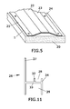
- Figure 3 shows a cross section view of a second attachment part for the corner parts of the building, for an example of an embodiment in which the energy apparatus comprises thermal tiles of equal thickness.
- Figure 4 shows a perspective view of a third part separating the energy apparatus.
- Figure 5 shows a perspective view of a first example of the embodiment of an anchoring body attached to a wall for affixing and anchoring of the supports for the energy apparatus, which includes anchoring wings.
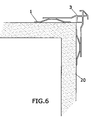
- Figure 6 shows an upper cross section view of a corner of a building provided with a corner support of the energy apparatus according to figure 3 .
- Figure 7 shows a diagram perspective view of mounting of a group of parts of figures 1, 2 , 4 and 5 supporting an energy apparatus.
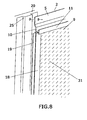
- Figure 8 shows a diagram in perspective view of mounting of a group of parts of figures 1, 2 , and 4 together with a body for anchoring to a vertical concrete wall.
- Figure 9 shows a cross section view of a first part which comprises the attachment device of the invention, for an example of an embodiment in which the energy apparatus comprises thermal tiles of different thickness.
- Figure 10 shows a cross section view of a second part for attachment of the corner parts of the building for an example of an embodiment in which the energy apparatus comprises at least two types of thermal tiles of different thickness.
- Figure 11 shows a cross section view of an additional horizontal part which comprises the attachment device of the invention for an example of an embodiment in which alternate rows are laid of thermal tiles with different thickness.
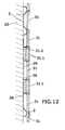
- Figure 12 shows a cross section view of a vertical plane of the mounting of a group of parts of figures 9 and 11 sustaining a series of energy apparatus or thermal tiles which occupy different thicknesses.
- an device for attaching energy apparatus to building façades which includes:
- the anchoring device in the invention includes an attachment part which may be fixed to one or both faces of a corner either directly, or through an anchoring part, such as that described previously.
- the horizontal supports preferably include an interior hollow or concavity which would be observed from the wall, providing an additional separation of the sustained energy apparatus, in such a way that the sum of the concavity of the horizontal support and that of the anchoring body provides adequate separation of the energy apparatus in respect to the wall on which they are fitted.
- a group of anchoring bodies (1, 25) are situated and attached to a wall (20), arranged in an essentially parallel form and coinciding or not with the lateral ends of each one of the sets of energy apparatus.
- Figure 7 shows an example of an embodiment on which said anchoring body (1) is provided with at least one lateral attachment wing (21) or with the facility for making holes (24) in said wing for their anchoring on said wall.
- the attachment body (1) comprises an attachment surface (22) with horizontal supports (2) using plugless screws. Said surface (22) is adequately sized to include the screws for one or more said horizontal supports (2), and which comprise lateral surfaces (23) which separate said surface (22) from the wall (20).
- Figure 8 shows an example of an embodiment in which the anchoring body (25) comprises a vertical concrete body.
- the horizontal supports (2) which are situated between said rows of energy apparatus (31) such as thermal tiles, as shown in figures 1, 2 and 9 , comprise a separation concavity (7) (seen from the wall,) formed at one end by the surface (5) and on the other by a support flap (8).
- Said horizontal supports (2) include a projection (30) emerging outwards which is provided at its end and visible surface (11) with an upper (10) or lower wedge (9) or stop, or both (9,10).
- the horizontal support (2) corresponding to figure 9 is provided with a gap (7) of a greater depth than that corresponding to the horizontal support (2) of figure 1 .
- the horizontal support (2) corresponds to the example in which, although it joins energy apparatus (31), such as thermal tiles, of equal thickness through the corresponding wedges or stops (9, 10) however, in those rows above or below these rows which are joined by the aforementioned horizontal support (2) there was at least one row of sets of energy apparatus which occupy a different thickness which may be formed by one or various thermal tiles (31), therefore the rest of the rows of energy apparatus (31) should present external surfaces aligned with those which occupy a greater thickness, so that those sets of energy apparatus (31) which take up less thickness will have a greater separation with respect to the wall (20), a function which is fulfilled, increasing the depth of the gap(7).
- energy apparatus such as thermal tiles
- FIG 11 shows an additional horizontal support (26) designed to join the respective rows of energy apparatus (31) which occupy a different thickness.
- a ceramic thermal tile (31) for example, is arranged, designed to occupy the upper external wedge or stop (28) and, for example, respective glass thermal tiles (31.1) which will jointly occupy the lower wedge or stop (29) and which could include separators (31.2) between them in order to provide an air chamber.
- a curtain wall may be established which reduces the passage of solar light, as well as reducing the internal temperature, providing the structure with a feeling of lightness.
- the horizontal support (26) instead of a gap to distance the thermal tile (31) from the wall (20), there is an upper intermediate partition (32).
- the horizontal support (26) comprises a projection (33) emerging towards the exterior which forms its end and visible surface (34).
- the horizontal support (2) corresponding to figure 9 comprises in its upper wedge or stop (10) a projection (35) for support of vertical separators (4).
- the separators (4) consist of H-shaped parts which will also have a function as adornment or trim.
- the hollows (19) in those H-shaped parts will house a portion of the sides of the energy apparatus (31) with the external surface (18) remaining visible.
- the corner parts (3) When a corner is reached, the corner parts (3), two of whose embodiments are represented in figures 3 and 10 , are fitted, which, as well as serving as adornment in the crests, also function as attachments.
- the corner parts (3) comprise projections (12) towards at least one of the sides of the corner and preferably towards two, preferably provided with a hole (13) for its attachment by means of screws to the corresponding anchor base (1, 25) and they define respective lateral compartments (15, 16) for arranging on these a portion of the energy apparatus (31).
- a preferably bevelled edge is arranged (27), with said bevel configuring a surface for connection between the lateral compartments (15, 16) which carries out the functions of structural reinforcement and adornment surface.
- a support zone (14) in the corresponding corner and reinforcement of the part (3) has also been provided.
- the corner part (3) corresponding to figure 3 is provided with a stepping (12.1) in the lateral projections (12), whereas in the corner part (3) corresponding to figure 10 the lateral projections (12) are situated continuing from the support zone (14) and therefore its face perpendicular (14.1) to the projections (12) acts as a distancer. Furthermore, this perpendicular face (14.1) has a greater depth than the stepping (12.1) which would permit the corner part (3) to adapt to the fact of having used thermal tiles (31) which occupy different thicknesses.
- the corresponding parts may be made of any material, including, but without being a restrictive list, metals (steel, aluminium) and plastics (PVC, Nylon, Pa etc.).
Applications Claiming Priority (1)
| Application Number | Priority Date | Filing Date | Title |
|---|---|---|---|
| ES200702127U ES1066338Y (es) | 2007-10-19 | 2007-10-19 | Dispositivo de agarre de aparatos energeticos en fachadas de edificaciones. |
Publications (2)
| Publication Number | Publication Date |
|---|---|
| EP2050897A2 true EP2050897A2 (de) | 2009-04-22 |
| EP2050897A3 EP2050897A3 (de) | 2011-01-19 |
Family
ID=38858811
Family Applications (1)
| Application Number | Title | Priority Date | Filing Date |
|---|---|---|---|
| EP08381030A Withdrawn EP2050897A3 (de) | 2007-10-19 | 2008-09-08 | Vorrichtung zur Befestigung von Energiepanelen an Gebäudefassaden |
Country Status (2)
| Country | Link |
|---|---|
| EP (1) | EP2050897A3 (de) |
| ES (1) | ES1066338Y (de) |
Cited By (3)
| Publication number | Priority date | Publication date | Assignee | Title |
|---|---|---|---|---|
| AT15995U1 (de) * | 2017-08-29 | 2018-10-15 | Prefa Aluminiumprodukte Gmbh | Befestigungsprofil |
| EP3613917A1 (de) * | 2018-08-21 | 2020-02-26 | Juan Ramón Hernampérez Cuesta | Halteklemme für fassadenverkleidungsstrukturen |
| AT17697U3 (de) * | 2022-02-09 | 2023-04-15 | Kremser Ing Helmut | Halterung für Bauelemente |
Citations (6)
| Publication number | Priority date | Publication date | Assignee | Title |
|---|---|---|---|---|
| EP0584047A1 (de) * | 1992-08-03 | 1994-02-23 | PARIFUR S.r.L. | Reihe von Elementen zum Gebrauch im belüfteten Fassadenbau |
| DE19804166A1 (de) * | 1997-01-17 | 1999-05-06 | Jerzy Dipl Ing Lech | Fassadenbekleidung mit Fassadenplatten |
| WO1999045219A1 (de) * | 1998-03-04 | 1999-09-10 | Gustav Kerle | Vorrichtung zur bekleidung von wänden mit flächigen teilen |
| US6289646B1 (en) * | 1999-03-26 | 2001-09-18 | Nichiha Co., Ltd. | Metal fixture assembly for installation of vertical sidings, construction and method of installation |
| US20020023398A1 (en) * | 2000-08-09 | 2002-02-28 | Nichiha Co., Ltd. | External wall construction, sealing fixture, external wall panel, and external wall constructing method |
| DE202004010160U1 (de) * | 2004-06-28 | 2004-10-28 | Riel, Harald | Universalprofil |
-
2007
- 2007-10-19 ES ES200702127U patent/ES1066338Y/es not_active Expired - Fee Related
-
2008
- 2008-09-08 EP EP08381030A patent/EP2050897A3/de not_active Withdrawn
Patent Citations (6)
| Publication number | Priority date | Publication date | Assignee | Title |
|---|---|---|---|---|
| EP0584047A1 (de) * | 1992-08-03 | 1994-02-23 | PARIFUR S.r.L. | Reihe von Elementen zum Gebrauch im belüfteten Fassadenbau |
| DE19804166A1 (de) * | 1997-01-17 | 1999-05-06 | Jerzy Dipl Ing Lech | Fassadenbekleidung mit Fassadenplatten |
| WO1999045219A1 (de) * | 1998-03-04 | 1999-09-10 | Gustav Kerle | Vorrichtung zur bekleidung von wänden mit flächigen teilen |
| US6289646B1 (en) * | 1999-03-26 | 2001-09-18 | Nichiha Co., Ltd. | Metal fixture assembly for installation of vertical sidings, construction and method of installation |
| US20020023398A1 (en) * | 2000-08-09 | 2002-02-28 | Nichiha Co., Ltd. | External wall construction, sealing fixture, external wall panel, and external wall constructing method |
| DE202004010160U1 (de) * | 2004-06-28 | 2004-10-28 | Riel, Harald | Universalprofil |
Cited By (4)
| Publication number | Priority date | Publication date | Assignee | Title |
|---|---|---|---|---|
| AT15995U1 (de) * | 2017-08-29 | 2018-10-15 | Prefa Aluminiumprodukte Gmbh | Befestigungsprofil |
| EP3450649A1 (de) * | 2017-08-29 | 2019-03-06 | Prefa Aluminiumprodukte Gesellschaft m.b.H. | Befestigungsprofil |
| EP3613917A1 (de) * | 2018-08-21 | 2020-02-26 | Juan Ramón Hernampérez Cuesta | Halteklemme für fassadenverkleidungsstrukturen |
| AT17697U3 (de) * | 2022-02-09 | 2023-04-15 | Kremser Ing Helmut | Halterung für Bauelemente |
Also Published As
| Publication number | Publication date |
|---|---|
| EP2050897A3 (de) | 2011-01-19 |
| ES1066338U (es) | 2008-01-01 |
| ES1066338Y (es) | 2008-04-01 |
Similar Documents
| Publication | Publication Date | Title |
|---|---|---|
| AU2011263360B2 (en) | A structural infill wall panel module | |
| US6099768A (en) | Modular building panel and method for constructing the same | |
| US9567752B2 (en) | Facade | |
| US7043884B2 (en) | Cladding system | |
| ES2364608T3 (es) | Sistema para el revestimiento de superficies. | |
| US10036156B1 (en) | Method of forming a three-dimensional structure having rigid wall panels | |
| US20120085042A1 (en) | Wall Panel Systems for Rigid Wall Panels | |
| WO1994004765A1 (en) | Stopless butt-joint multiple curtainwall system | |
| EP1712694A1 (de) | Vorgehängte Fassade | |
| WO2008113207A1 (fr) | Panneau mural extérieur et son procédé de montage | |
| RU2557269C1 (ru) | Способ монтажа облицовки фасада и теплоизоляции с плиты межэтажного перекрытия | |
| EP2050897A2 (de) | Vorrichtung zur Befestigung von Energiepanelen an Gebäudefassaden | |
| US20230383537A1 (en) | Systems, methods and apparatus for interlocking unitized curtainwall building façade | |
| EP0195662A2 (de) | Tragkonstruktion für Verkleidungsplatten | |
| WO2009059392A1 (en) | Apparatus and method for installing cladding to structures | |
| US11203876B2 (en) | Metal or alloy framed insulated building cladding system | |
| EP2449185B1 (de) | Zusätzliches isoliersystem und ein verfahren zur isolierung einer fassade | |
| EP3656941A1 (de) | Vakuumisolationspaneelsystem | |
| RU158890U1 (ru) | Сендвич-панель | |
| CN212507184U (zh) | 一种保温装饰板的装配结构 | |
| JP3370253B2 (ja) | 建物の断熱パネル及び断熱パネル構造 | |
| DI NASO et al. | GLASS FAÇADE [in:] Sustainable Buildings. Development of Low Energy and Eco-Friendly Constructions | |
| WO2002095162A1 (en) | Brick slip fixture system | |
| EP2546426A2 (de) | Vorgefertigtes Bauelement zur Herstellung von Mauern und Mauer bestehend aus solchen Bauelementen | |
| NO347475B1 (en) | Façade insulating system |
Legal Events
| Date | Code | Title | Description |
|---|---|---|---|
| PUAI | Public reference made under article 153(3) epc to a published international application that has entered the european phase |
Free format text: ORIGINAL CODE: 0009012 |
|
| AK | Designated contracting states |
Kind code of ref document: A2 Designated state(s): AT BE BG CH CY CZ DE DK EE ES FI FR GB GR HR HU IE IS IT LI LT LU LV MC MT NL NO PL PT RO SE SI SK TR |
|
| AX | Request for extension of the european patent |
Extension state: AL BA MK RS |
|
| PUAL | Search report despatched |
Free format text: ORIGINAL CODE: 0009013 |
|
| AK | Designated contracting states |
Kind code of ref document: A3 Designated state(s): AT BE BG CH CY CZ DE DK EE ES FI FR GB GR HR HU IE IS IT LI LT LU LV MC MT NL NO PL PT RO SE SI SK TR |
|
| AX | Request for extension of the european patent |
Extension state: AL BA MK RS |
|
| 17P | Request for examination filed |
Effective date: 20110715 |
|
| AKX | Designation fees paid |
Designated state(s): AT BE BG CH CY CZ DE DK EE ES FI FR GB GR HR HU IE IS IT LI LT LU LV MC MT NL NO PL PT RO SE SI SK TR |
|
| STAA | Information on the status of an ep patent application or granted ep patent |
Free format text: STATUS: THE APPLICATION IS DEEMED TO BE WITHDRAWN |
|
| 18D | Application deemed to be withdrawn |
Effective date: 20110720 |