EP2050418B1 - Adjustable wheelchair for pets - Google Patents
Adjustable wheelchair for pets Download PDFInfo
- Publication number
- EP2050418B1 EP2050418B1 EP08017963A EP08017963A EP2050418B1 EP 2050418 B1 EP2050418 B1 EP 2050418B1 EP 08017963 A EP08017963 A EP 08017963A EP 08017963 A EP08017963 A EP 08017963A EP 2050418 B1 EP2050418 B1 EP 2050418B1
- Authority
- EP
- European Patent Office
- Prior art keywords
- leg
- wheelchair
- clamp
- harness
- support frame
- Prior art date
- Legal status (The legal status is an assumption and is not a legal conclusion. Google has not performed a legal analysis and makes no representation as to the accuracy of the status listed.)
- Active
Links
Images


Classifications
-
- A—HUMAN NECESSITIES
- A61—MEDICAL OR VETERINARY SCIENCE; HYGIENE
- A61D—VETERINARY INSTRUMENTS, IMPLEMENTS, TOOLS, OR METHODS
- A61D3/00—Appliances for supporting or fettering animals for operative purposes
Definitions
- the present invention relates generally to walking aids for animals. Particularly, the present invention relates to mobile devices for disabled animals. More particularly, the present invention relates to mobile devices for injured or partially-immobilized animals such as cats and dogs.
- U.S. Patent No. 6,820,572 (2004, Parkes ), corresponding to US 2004/023 1613 , discloses a prosthetic apparatus for disabled four-legged animals.
- the apparatus is a cart with a chassis.
- the chassis includes a front subassembly detachably mounted to a rearward subassembly.
- a primary wheel is mounted to the frame of the chassis at each side of the rearward end and a set of swively mounted secondary wheels is mounted to the frame at each side of the forward end.
- a yoke extends across the frame at the forward end and is movable from an active position spanning the side walls of the frame to an inactive position away from one of the side walls to permit entrance and exit of the animal from the cart.
- U.S. Patent No. 5,224,444 (1993, Hill et al. ) discloses a walking aid for a four-legged animal.
- the walking aid includes a cradle attachable below the animal's hind quarters, and a support member pivotally attached to the cradle.
- a wheel arrangement is provided on the support member at its end remote from the cradle. Resiliency is provided for biasing the support member below the cradle.
- U.S. Patent No. 4,821,676 (1989, Hulterstrum ) discloses a cart assembly for a partially-immobilized animal.
- the cart assembly includes a plastic cradle adapted to support and partially encompass the hind portion of the animal, wheels connected to the plastic cradle for mobility, and a harness that is secured over the head of the animal and secured to the cradle.
- U.S. Patent No. 4,375,203 (1983, Parkes ) discloses a prosthetic cart for animals.
- the cart has a yoke attachable to the animal's thorax, a hip support member for carrying the animal's rear quarters, a shin support for the animal's rear legs, and a pair of wheels.
- the cart also includes a pair of adjustment blocks that each has a plurality of axle holes. The axle is positioned with respect to the cart to approximate a balanced support of the rear quarters.
- U.S. Patent No. 3,406,661 (1968, Parkes ) discloses an apparatus for suspending the hindquarters of a crippled household pet.
- the apparatus includes a standard formed of spaced shafts interconnected adjacent their upper ends and rotatably mounting a wheeled axle adjacent their lower ends, an upper and lower clamp device for each shaft, a shoulder unit formed of spaced parallel shafts having an integrally formed front yoke for embracing the shoulder area and providing spaced rear ends, and a suspension unit formed of spaced parallel shafts having an integrally formed lower abdominal sling merging into a pair of rear leg loops.
- U.S. Patent No. 3,215,117 (1965, Short ) discloses a veterinary paraplegic cart.
- the cart includes an inverted U-shaped frame, wheels mounted on the frame, a shaped saddle bar adjustably secured to the frame, a preformed saddle secured to the saddle bar, a horizontal bar fitted to the front body area of the animal, rearwardly extending elongated rods with a fastening mechanism that is detachably connected to the horizontal bar and connected to the frame.
- US Patent N° 3,241,851 (1966, Dingbaum ) discloses a mobile animal support comprising, a pair of substantially identically constructed opposed supporting units which are adjustably interconnected to provide the desired support for the animal.
- the prior art devices all suffer from various disadvantages. All of the prior art devices must be made to order and custom designed to the measurements of the animal. Some of the prior art devices can be adjusted based on the height and length of the animal but the wheel legs cannot be angularly adjusted relative to the horizontal axis of the device. Because they are custom-made, prior art carts cannot be returned or used on another animal unless the other animal has the same height, length and width measurements as the original animal for which the cart was made. In addition, the prior art carts tend to be bulky and more difficult to transport.
- the present invention achieves these and other objectives by providing a wheelchair for animals having a harness support frame, first and second knuckle clamp assemblies, a plurality of harness connectors, first and second leg assemblies, and first and second wheels attached adjacent to the distal end of the first and second leg assemblies.
- the harness support frame is generally U-shaped and includes first and second lateral supports spaced from each other with a width extender adjustably connected between the first and second lateral supports at or adjacent to a proximal end (i.e. the end forming the base of the "U" shape) of the harness support frame.
- the first and second knuckle clamp assemblies have a first clamp component and a second clamp component that adjustably interlock to provide for selective circumferential positioning of the second clamp component relative to the first clamp component. It is the knuckle clamp assembly that provides the collapsibility of the wheelchair for transportation as well as the angular adjustment of the leg assembly relative to the harness support frame.
- Each of the first clamp components has a lateral bore sized to slidably and matingly receive one of the first and second lateral supports therethrough.
- the first clamp component also includes a locking mechanism to securely position the first clamp component in a desired location along the lateral support to accommodate the length of a particular animal.
- the second clamp component has a clamp recess for securely receiving the leg assembly.
- the plurality of harness connectors is positionable, yet securely fixable, in various locations on the harness support frame. This flexibility provides for accommodating various types of animal harnesses that are configured for a particular ailment or injury. For instance, the harness for an animal with a broken leg is structurally different than a harness for a paraplegic animal since the support requirements are different.
- the adjustable positioning of the plurality of harness connectors is designed to accommodate these different requirements without the need to custom make each harness support frame.
- First and second leg assemblies are removably connected to the second clamp component of the knuckle clamp assemblies.
- the clamp recess of the second clamp component receives in sliding and mating engagement a proximal end of the leg assemblies.
- the proximal end of the leg assemblies is secured to the second clamp component to prevent inadvertent or accidental disconnection of the leg assemblies from the knuckle clamp assemblies.
- a wheel is rotatably connected adjacent to each of the distal ends of the leg assemblies.
- the wheels may be sized for the terrain, for example, a larger diameter wheel for soft sand or uneven terrain and a smaller diameter wheel for hard surfaces.
- the leg assemblies may optionally include leg extenders that are preferably telescopically connected to the distal end of the leg assemblies.
- a leg lock mechanism is employed to securely lock the leg extender at a pre-selected position depending on the height of the animal being fitted and the diameter of the wheels used on the leg assemblies. The wheels are then rotatably connected adjacent to the distal end of the leg extender.
- the leg lock mechanism may be a button and hole device, a twist and lock device, a collar mechanism, a locking pin, or a set screw, and the like.
- the button and hole device is a biased "button" or pin that mates with a locking hole in the leg assembly.
- the biasing mechanism forces the "button” or pin into a hole in the leg assembly with which it is aligned.
- the twist and lock device is typically a compression-type fitting on the leg assembly that surrounds the leg extender and compressibly holds the leg extender at a pre-selected and extended position. This type of mechanism is used on adjustable ski poles. An optional set screw may be incorporated in the leg assembly to prevent inadvertent or accidental disengagement of the leg lock mechanism.
- the width extender of the harness support frame is preferably telescopically connected to the first and second lateral supports at the proximal end of the harness support frame.
- a frame lock mechanism is employed to securely lock the width extender at a pre-selected position, depending on the width of the animal.
- the frame lock mechanism for the width extender may be a button and hole device, a twist and lock device, a collar mechanism, a locking pin, or a set screw, and the like.
- An optional set screw may also be incorporated in the first and second lateral supports to prevent the inadvertent or accidental disengagement of the frame locking mechanism.
- the harness support frame may optionally include first and second lateral extenders at the distal end of the first and second lateral supports.
- the lateral extenders are preferably telescopically connected to the first and second lateral supports.
- a lateral lock mechanism is also preferably employed to securely lock the lateral extenders at a pre-selected position, depending on the length of the animal.
- the lateral lock mechanism may take any form that securely locks the lateral extender at a pre-selected extension. Examples of some of these devices include a button and hole device, a twist and lock device, a collar mechanism, a locking pin, a set screw, and the like. An optional set screw may also be incorporated for the same reasons as stated above for the previously described extenders.
- indicia may be incorporated or applied thereon to facilitate proper sizing for a range of animal dimensions.
- These indicia may be actual measurement marks such as inches or centimeters, or they may be color coded with a color coding chart designed specifically for various animal sizes (i.e. small, medium and large or height, width and length).
- the color coding may be used for proper selection of the extenders that accommodate animals within a predefined size range as well as for ease of assembly.
- the leg extenders may have indicia that match indicia on the leg assembly while the lateral extenders may have a different indicia that matches the first and second lateral supports.
- the plurality of harness connectors may also have indicia or the harness support frame may have indicia to easily select placement of the harness connectors on the harness support frame depending on the harness to be used and the size of the animal.
- the present invention may also include optional features such as (1) a foot stabilizer that attaches to the leg assembly and extends away from the leg assembly to prevent over-rotation of the harness frame support relative to the wheels, (2) a stabilizer bar that attaches between the lateral supports and extends above the harness frame support to accommodate the body of the animal, to stabilize the lateral extenders and to provide an assist handle for use by the animal's keeper, and (3) a shock absorber connected to the leg assemblies to dampen wheel impacts.
- a foot stabilizer that attaches to the leg assembly and extends away from the leg assembly to prevent over-rotation of the harness frame support relative to the wheels
- a stabilizer bar that attaches between the lateral supports and extends above the harness frame support to accommodate the body of the animal, to stabilize the lateral extenders and to provide an assist handle for use by the animal's keeper
- a shock absorber connected to the leg assemblies to dampen wheel impacts.
- Adjustability is the key characteristic of the present invention.
- This key characteristic includes the ability to adjust the length of the harness support frame, the width of the harness support frame, the height of the harness support frame, and the collapsibility of the rotatable knuckle clamp assemblies allowing the leg assemblies to rotate and be positioned parallel with the harness support frame for easy transportation.
- the rotatable knuckle clamp assemblies also provides angular adjustment of the leg assemblies relative to the harness support frame. This adjustability eliminates the need for custom designing a wheelchair/cart for a particular animal. It also eliminates the need for accurate measurements of the animal in order to obtain the custom designed wheelchair/cart.
- the present invention's adjustability allows the end user to make the necessary adjustments for the end user's animal.
- the present invention can be easily adjusted to fit various size animals making the device re-usable.
- the same wheelchair or cart since it is not custom made, can be resold or leased.
- the adjustability of the present invention eliminates or minimizes the need to purchase a new wheelchair or cart if the animal outgrows it. A simple readjustment is typically all that is required.
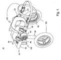
- FIGURE 1 is a perspective front view of the present invention showing an adjustable wheelchair for four-legged animals.
- FIGURE 2 is an enlarged, expanded and perspective view of the knuckle clamp assembly of the present invention.
- FIGURE 2A is a cross-sectional view of the knuckle clamp assembly of the present invention.
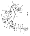
- FIGURE 3 is an exploded, front, perspective view of the present invention showing the components of the present invention.
- FIGURE 4 is a front end view of the present invention showing the angle ⁇ to the vertical of the leg assemblies.
- FIGURE 5 is a perspective front view of the present invention showing an adjustable wheelchair for animals in a collapsed position for transport.
- FIGURES 6A and 6B are side views of the present invention showing a stability extension on a leg of the present invention situated on a surface.
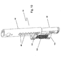
- FIGURE 7 is a magnified view of the stability extension shown in Figs. 6A and 6B .
- FIGURE 8 is a perspective view of the present invention without the harness assembly showing a front stabilizer bar.
- FIGURE 9 is a perspective rear view of the present invention showing optional shock absorbers on the wheeled legs.
- FIGURE 10 is an enlarged perspective view of one leg of the present invention showing the shock absorber.
- FIG. 1 The wheelchair for four-legged animals 10 is shown in Fig. 1 .
- Wheelchair 10 includes a harness support frame 20, a first and second knuckle clamp assembly 40, a plurality of harness connectors 60, first and second leg assemblies 80, first and second wheels 100 attached adjacent to the distal end 90 of first and second leg assemblies 80, and a harness assembly 120.
- Harness support frame 20 includes first and second lateral supports 22, 24 that are spaced from each other. First and second lateral supports 22, 24 are connected to each other at frame proximal end 26 by a width extender 28 (shown in Fig. 2 ).
- Proximal end 26 gives harness support frame 20 a U-shaped structure that typically receives the hindquarters of an animal needing support.
- First and second lateral supports 22, 24 include a plurality of apertures 31 that are used in conjunction with a spring button for adjusting the length and width of harness support frame 20.
- Harness assembly 120 includes any sub-component that connects harness support frame 20 to an animal or supports a portion of the animal's body.
- First and second knuckle clamp assembly has a locking component 48.
- Harness assembly 120 includes a harness hindquarter component 122, a harness leg support 124 and an animal body harness 126, which are more clearly delineated in Fig. 3 .
- Knuckle clamp assembly 40 includes a first clamp component 42 and a second clamp component 46.
- Second clamp component 46 adjustably interlocks with first clamp component 42 to provide for selective circumferential positioning of second clamp component 46 relative to first clamp component 42.
- the inter-component lock interface may include a plurality of ridges 45 shown on the opposing surface of first clamp component 42 that mates with a plurality of elongated, complimentary recesses on the opposing surface of second clamp component 46.
- One or more notches 50 may also be incorporated in the outer peripheral surface of both first and second clamp components 42, 46 to indicate a pre-selected alignment such as the position when leg assemblies 80 are perpendicular to harness support frame 20 or other selected angle. It should be understood that any interlocking interface between the opposing surfaces of the first and second clamp components 42, 46 may be used to prevent slippage when locked into a user-selected position. It is also noted that second clamp component 46 may rotate a full 360° relative to first clamp component 42 or any subset of rotational angles less than 360°. The preferred angle of the leg assemblies 80 to the lateral supports 22, 24 when supporting an animal is in a range of about 13° to about 17° from the vertical toward the proximal end 26.
- first clamp component 42 includes a first clamp housing 42a and a first clamp interlock component 42b.
- First clamp component 42 has a lateral bore 52 to slidably receive one of first and second lateral supports 22, 24 therethrough.
- Lateral bore 52 includes a plurality of protrusions 43 spaced to coincide with the spacing of the adjustment apertures 31 of lateral supports 22, 24.
- Protrusions 43 not only provide alignment support to knuckle clamp assembly 40 when connecting it to lateral supports 22, 24 but also prevent the preferred spring button used for adjusting the length of the harness support frame to the animal from being inadvertently positioned in a button receiving aperture 31 that is inside the knuckle clamp assembly 40 and, thus, inaccessible for future adjustment without taking knuckle clamp assembly 40 apart.
- First clamp component 42 includes a knuckle-to-frame locking mechanism 44 to securely position first clamp component 42 in a desired location along lateral supports 22, 24. Adjustability of first clamp component 42 on lateral supports 22, 24 provides a means to improve the balance of wheelchair 10 to the animal to be supported.
- Second clamp component 46 includes a second clamp housing 46a and a second clamp interlock component 46b.
- Second claim component 46 includes a clamp recess 47 and a knuckle clamp lock mechanism 48.
- Clamp recess 47 receives leg assembly 80 while knuckle clamp lock mechanism 48 provides for adjustably interlocking second clamp component 46 to first clamp component 42 and providing selective circumferential positioning of second clamp component 46 relative to first clamp component 42.
- Figure 2A is a cross-sectional view of knuckle clamp assembly 40.
- knuckle clamp assembly 40 One important aspect of knuckle clamp assembly 40 is the angled aperture 52 relative to the vertical. As explained below, it is this angle that sets the angle of the leg assembly 80 to the harness support frame 20.
- width extender 28 of harness support frame 20 is preferably telescopically connected to the first and second lateral supports 22, 24 and defines the spatial distance between first and second lateral supports 22, 24.
- harness support frame 20 can be adjusted to accommodate various animal width sizes without having to take exact measurements of the animal to be fitted to wheelchair 10.
- a frame lock mechanism 30 is employed to securely lock width extender 28 at a pre-selected position, depending on the space between first and second lateral supports 22, 24 desired.
- Frame lock mechanism 30 may be a button and hole device, a twist and lock device, a collar mechanism, a locking pin, a set screw, and the like.
- a button and hole device coupled with a set screw is preferably used.
- first and second lateral supports 22, 24 include a plurality of apertures 31 for receiving the interlocking "button.” Further included are set screws 33 adjacent the junctions between first and second lateral supports 22, 24 and width extender 28 to securely lock the pre-selected position and prevent the inadvertent or accidental disengagement of frame lock mechanism 30.
- First and second lateral supports 22, 24 are preferably L-shaped, integral components but may also be an assembly of removably attachable sub-components.
- the plurality of harness connectors 60 are adjustably connected on first and second lateral supports 22, 24 and are positionable, yet lockable, in various locations on harness support frame 20.
- a total of six to eight harness connectors 60 is typically used to support the harness assembly 120. More or less harness connectors 60, however, may be used depending on the harness configuration to be attached to the harness support frame 20 and the size of the animal to be supported.
- harness connectors 60 are quick-release clips or buckles typically found on backpacks, etc., where a frame portion 62 of the clip or buckle is fastened to the harness support frame 20 and the mating harness portion 64 of the clip or buckle is fastened to the harness assembly 120.
- Harness connectors 60 include a locking structure that provides for fixedly securing each harness connector 60 to a pre-selected location.
- the locking structure may be a bolting device, a locking pin, a screw, a set screw, a rivet, and the like.
- the preferred method of fixedly attaching harness connectors 60 to the harness support frame 20 is to use the optional set screws 33 of the harness support frame 20.
- Leg assembly 80 includes at least a leg support 82 having a leg proximal end 82a and a leg distal end 82b.
- Leg support 82 may optionally include a plurality of longitudinally-spaced apertures 85.
- Leg proximal end 82a is removably connected to and received into clamp recess 47.
- An optional leg extender 90 is telescopically received by leg distal end 82b and adjustably connected to leg support 82.
- a leg lock mechanism 92 is employed to selectively fix the length of leg assembly 80 and securely hold leg extender 90 at a pre-selected extension.
- leg lock mechanism 92 may be a button and hole device, a twist and lock mechanism, a locking pin, a collar mechanism, a set screw, and the like.
- leg extender 90 has a push button that engages one of the plurality of leg apertures 85.
- leg support 82 may incorporate a plurality of axle apertures to adjustably attach wheels 100. Wheels 100 are mounted on individual axles 102 adjacent the leg distal end 84.
- Figure 4 illustrates a front view of wheelchair 10.
- Leg assemblies 80 are attached to second clamp components 46 and are shown extending at a downward angle ⁇ to the outside of harness support frame 20.
- the angle ⁇ is preferably in the range of 0° to about 10° from the vertical. More preferably, the angle is 5°.
- the angle ⁇ to the leg assemblies 80 relative to the first and second lateral supports 22, 24 is provided by forming the lateral support bore 52 in first clamp component 42 at the desired angle relative to the knuckle clamp longitudinal axis 200. This was more clearly shown in Fig. 2A .
- the clamp recess 47 may alternatively be formed in second clamp component 46 at the desired angle relative to knuckle clamp longitudinal axis 200.
- FIG. 5 there is illustrated wheelchair 10 in a collapsed/folded position.
- first and second lateral supports 22, 24 are in their closest spatial arrangement at proximal end 26.
- Lateral extenders 36 are fully retracted relative to first and second lateral supports 22, 24.
- Leg extenders 90 are also in their fully retracted position relative to leg assemblies 80.
- leg assemblies 80 are rotated to a position where leg assemblies 80 are parallel to first and second lateral supports 22, 24. It should be noted that the extenders do not have to be in their fully retracted position to place wheelchair 10 in the collapsed/folded position. It is only recommended when it is desired that wheelchair 10 be in its most compact configuration for transport.
- knuckle clamp assembly 40 has a dial-type knuckle lock mechanism 48 that is rotatable between a locked position and an unlocked position. Knuckle lock mechanism 48 releases second clamp component 46 from its interlocking engagement with first clamp component 42. Once released, second clamp component 46 can be rotated about the knuckle longitudinal axis 200 and then re-engaged with first clamp component 42 to secure wheelchair 10 for transport.
- Figures 6A and 6B are side views of wheelchair 10 without the harness assembly 120 but showing the optional foot stabilizer 130.
- Optional foot stabilizer 130 is connected near the distal end 85 of leg assembly 80 and preferably extends towards the back of wheelchair 10. Foot stabilizer 130 prevents wheelchair 10 from over-rotating about wheels 100 such that harness frame distal end 26 would contact the ground 1 but for foot stabilizer 130. This is more clearly shown in Fig. 6B . Because an animal harnessed to wheelchair 10 can also sit while attached to wheelchair 10, optional foot stabilizer 130 prevents any inadvertent backward tipping of the cart caused by the animal's movement to a sitting position, which could lead to injury to the attached animal since the animal already has limited use of its hindquarters.
- FIG. 7 is an enlarged, perspective view of foot stabilizer 130.
- foot stabilizer 130 is shown as a U-shaped bar having a foot proximal end 132 connected to leg extension 90 at the wheel connection 103.
- Figure 7 also more clearly shows another feature of leg extension 90.
- leg extension 90 is an elongated tube having a channel 91 longitudinally extending along the length of one or both opposed sides of leg extension 90. Channel 91 engages with a mating structure on the inside of leg support 82, which also extends along the length of leg support 82.
- This structural configuration facilitates alignment of the push button with the sizing apertures 85 in leg support 82.
- the flat surface of the channel also provides a surface for the optional set screws 93.
- Width extender 28 and lateral extenders 36 may also optionally have the same or similar structure, which facilitates alignment of the push button in lateral extenders 36 and width extender 28 with the sizing apertures 31 in the lateral supports 22, 24.
- Harness support frame 20 may also include an optional stabilizer bar 140.
- Stabilizer bar 40 is preferably removably, but securely, attached to lateral extenders 22, 24 and extends above the plane of harness support frame 20. Stabilizer bar 40 has several purposes. It stabilizes lateral extenders 22, 24 about the animal when the harness assembly 120 is attached to the animal and it also provides a handle for the animal's keeper to assist the animal is difficult situations.
- Fig. 9 is a rear perspective view of the wheelchair 10 with an optional shock absorber 150 on each leg assembly 80.
- the use of optional shock absorber 150 eliminates the need for adjustment mechanism 92 or optional set screw 93. Shock absorber 150 provides for a less jarring experience for the animal harnessed into wheelchair 10. It should be understood that shock absorber 150 made be incorporated in any position on leg assembly 80 so long as it provides shock absorbing characteristics between wheel 100 and leg support 82. Particularly, shock absorber 150 may be configured internally within leg assembly 80 instead of externally as shown in Fig. 9 .
- FIG 10 is an enlarged perspective view of leg assembly 80 showing shock absorber 150.
- shock absorber 150 is externally configured to leg assembly 80 and has a first and second absorber support 152 and 154, respectively.
- First absorber support 152 securely attaches one end of shock absorber 150 to leg support 82 and second absorber support 154 securely attaches the other end of shock absorber 150 to leg extension 90.
- the total adjustability feature of wheelchair 10 eliminates the need for a user to take careful measurements of the animal's length, width and height.
- the user only needs to know the animal's relative size, i.e. small, medium or large or other designation, in order to obtain a wheelchair 10 that is designed to be adjustable for the animal's true size. After having received wheelchair 10, the user can easily make the final sizing adjustments for the user's animal.
- wheelchair 10 is in the collapsed position for transport as shown in Fig. 5 .
- Wheelchair 10 is opened from the collapsed position by unlocking knuckle lock mechanism 48 on each knuckle clamp assembly 40 and rotating leg assembly 80 to the position that is perpendicular to harness support frame 20. Once leg assembly 80 is in position, knuckle lock mechanism 48 is re-locked to secure leg assembly 80 into position.
- Leg assembly 80 may be perpendicular to the harness support frame 20 or, preferably, set to an angle as previously discussed for better stability when attached to the animal.
- leg lock mechanism 92 is disengaged and leg extender 90 is extended to a second position where leg lock mechanism 92 is re-engaged such that the harness support frame is positioned for the height of the animal to be supported.
- the width of the harness support frame is adjusted for the width of the animal.
- the frame lock mechanism is disengaged from the first and second lateral supports 22, 24 and first and second lateral supports 22, 24 are adjusted by separating first and second lateral supports 22, 24 from each other along the width extender 28 to the width of the animal to be supported. Once the proper width/spacing between first and second lateral supports 22, 24 is achieved, frame lock mechanism is re-engaged. If the length of harness support frame 20 needs to be adjusted, then the lateral lock mechanism is disengaged and lateral extenders 36 are extended the desired distance for the length of the animal to be supported. The lateral lock mechanism is then re-engaged.
- the harness assembly 120 is removably attached to the animal and then connected to the plurality of harness connectors 60 on harness support frame 20. Depending on the design of the harness used, the position of the plurality of harness connectors 60 may need to be re-positioned on harness support frame 20.
- the user may collapse wheelchair 10 for transport.
- the user may either fully collapse wheelchair 10 or only rotate leg assemblies 80 to a parallel position with harness support frame 20 by unlocking the knuckle lock mechanism 48, rotating the leg assemblies 80 to the desired position and re-locking knuckle lock mechanism 48.
- optional set screws 33 on harness support frame 20 and optional set screws 93 on leg assemblies 80 may be engaged to further secure the positions of the width extender 28, lateral extenders 36 and leg extenders 90.
Landscapes
- Life Sciences & Earth Sciences (AREA)
- Veterinary Medicine (AREA)
- Health & Medical Sciences (AREA)
- Zoology (AREA)
- Engineering & Computer Science (AREA)
- Wood Science & Technology (AREA)
- Animal Husbandry (AREA)
- Animal Behavior & Ethology (AREA)
- General Health & Medical Sciences (AREA)
- Public Health (AREA)
- Housing For Livestock And Birds (AREA)
- Catching Or Destruction (AREA)
- Handcart (AREA)
- Carriages For Children, Sleds, And Other Hand-Operated Vehicles (AREA)
Applications Claiming Priority (1)
| Application Number | Priority Date | Filing Date | Title |
|---|---|---|---|
| US11/874,555 US7549398B2 (en) | 2007-10-18 | 2007-10-18 | Adjustable wheelchair for pets |
Publications (3)
| Publication Number | Publication Date |
|---|---|
| EP2050418A2 EP2050418A2 (en) | 2009-04-22 |
| EP2050418A3 EP2050418A3 (en) | 2009-05-13 |
| EP2050418B1 true EP2050418B1 (en) | 2010-02-17 |
Family
ID=40303595
Family Applications (1)
| Application Number | Title | Priority Date | Filing Date |
|---|---|---|---|
| EP08017963A Active EP2050418B1 (en) | 2007-10-18 | 2008-10-14 | Adjustable wheelchair for pets |
Country Status (7)
| Country | Link |
|---|---|
| US (1) | US7549398B2 (enExample) |
| EP (1) | EP2050418B1 (enExample) |
| JP (1) | JP5385584B2 (enExample) |
| AT (1) | ATE457702T1 (enExample) |
| CA (1) | CA2641092C (enExample) |
| DE (1) | DE602008000666D1 (enExample) |
| ES (1) | ES2339303T3 (enExample) |
Families Citing this family (37)
| Publication number | Priority date | Publication date | Assignee | Title |
|---|---|---|---|---|
| US8038158B1 (en) * | 2008-09-22 | 2011-10-18 | White Cynthia M | Infant crawler |
| WO2011027088A1 (fr) * | 2009-09-07 | 2011-03-10 | Roland De La Celle | Dispositif de reeducation ou d'assistance a la mobilite d'un animal quadrupede |
| US9179646B2 (en) | 2010-07-11 | 2015-11-10 | Nekuda D.M. Technologies And Design Ltd. | Walking aid for disabled four-legged animals |
| US20130040279A1 (en) * | 2011-08-12 | 2013-02-14 | Dawn LANE | Bridle and halter instructional system |
| US8961500B2 (en) | 2012-03-28 | 2015-02-24 | Medtronic Navigation, Inc. | Navigated instrument with a stabilizer |
| US9089109B2 (en) * | 2013-03-06 | 2015-07-28 | Daniel Codos | Force transfer harness and method |
| JP6296896B2 (ja) * | 2014-05-20 | 2018-03-20 | 株式会社松本義肢製作所 | ペット用車椅子 |
| US20160050879A1 (en) * | 2014-08-21 | 2016-02-25 | Ip Holdings, Inc. | Livestock support system |
| CN104473735A (zh) * | 2014-12-18 | 2015-04-01 | 上海第二工业大学 | 一种宠物犬轮椅 |
| US9962249B2 (en) * | 2015-07-29 | 2018-05-08 | Sylvan, Inc. | Mobility aid for quadrupeds |
| ITUB20153031A1 (it) * | 2015-08-10 | 2017-02-10 | Amil S R L | Carrello di ausilio alla deambulazione di animali |
| USD804112S1 (en) * | 2015-10-30 | 2017-11-28 | Sylvan, Inc. | Mobility aid for quadrupeds |
| CN106691789B (zh) * | 2016-12-19 | 2019-04-02 | 惠州市格雷戈里科技有限公司 | 助残车 |
| US10765087B1 (en) * | 2017-01-31 | 2020-09-08 | Loma Linda Academy | Walker for animals |
| JP6715195B2 (ja) * | 2017-02-09 | 2020-07-01 | 株式会社ピカコーポレイション | 動物用ハーネス |
| KR101986202B1 (ko) * | 2018-03-12 | 2019-06-05 | 인천대학교 산학협력단 | 애완동물용 돌출행동 차단장치 |
| KR101899553B1 (ko) * | 2018-04-23 | 2018-09-17 | 김기연 | 애완 동물 보행 보조기 |
| CN109431663B (zh) * | 2018-10-27 | 2020-10-23 | 周盈裕 | 一种残疾哈巴狗后腿行走义肢 |
| EP3937844A4 (en) | 2019-03-13 | 2022-10-12 | Handicapped Pets, Inc. | Pet mobility carrier assembly |
| US10994761B2 (en) | 2019-03-20 | 2021-05-04 | Susan Chappell | Low profile cart with access ramp |
| CN110327165B (zh) * | 2019-07-11 | 2020-09-18 | 青岛大学附属医院 | 一种产科产后综合护理器及其使用方法 |
| WO2021024967A1 (ja) * | 2019-08-05 | 2021-02-11 | 洋明 是枝 | 四足動物用車椅子 |
| KR102546405B1 (ko) * | 2020-02-27 | 2023-06-23 | 이은재 | 동물용 보행 보조기구 |
| ES2868548A1 (es) * | 2020-04-21 | 2021-10-21 | Llorens Mario Pedret | Aparato ortopédico de asistencia a la movilidad de animales cuadrúpedos discapacitados de sus extremidades posteriores |
| USD919200S1 (en) * | 2020-09-07 | 2021-05-11 | Shenzhen Ailin Trading Co., Ltd | Pet wheelchair |
| CN112450114A (zh) * | 2020-12-07 | 2021-03-09 | 陈桂军 | 一种针对体型较大的残疾、瘫痪宠物观光车 |
| USD987917S1 (en) * | 2021-08-22 | 2023-05-30 | Nengfei Li | Adjustable pet wheelchair |
| USD987918S1 (en) * | 2021-08-23 | 2023-05-30 | Nengfei Li | Adjustable pet wheelchair |
| USD977767S1 (en) * | 2021-08-24 | 2023-02-07 | Nengfei Li | Adjustable pet wheelchair |
| USD987921S1 (en) * | 2021-10-19 | 2023-05-30 | Nengfei Li | Adjustable pet wheelchair |
| EP4514296A1 (en) * | 2022-04-28 | 2025-03-05 | Handicapped Pets, Inc. | Wheelchair device for mobility-challenged quadrupeds with user-actuated sit-down action |
| CN117615649A (zh) * | 2022-06-20 | 2024-02-27 | 日光技术株式会社 | 四腿动物用轮椅 |
| KR20250033612A (ko) | 2023-09-01 | 2025-03-10 | 핀에스코리아(주) | 강아지용 휠체어 |
| USD1089898S1 (en) * | 2023-12-09 | 2025-08-19 | Yunlei Zhang | Adjustable pet wheelchair |
| US12268192B1 (en) * | 2023-12-13 | 2025-04-08 | King Fahd University Of Petroleum And Minerals | Motorized animal walker |
| USD1104377S1 (en) * | 2024-05-07 | 2025-12-02 | Guangzhou Fashoula Pet Products Co., Ltd. | Pet wheelchair |
| USD1047314S1 (en) * | 2024-07-13 | 2024-10-15 | Jibo Tu | Pet wheelchair |
Family Cites Families (20)
| Publication number | Priority date | Publication date | Assignee | Title |
|---|---|---|---|---|
| US1879915A (en) * | 1929-06-10 | 1932-09-27 | Janie Irene Carroll | Portable animal bath |
| US2546726A (en) | 1948-09-30 | 1951-03-27 | Jr Carl C Creamer | Mobile sling for crippled animals |
| US2976840A (en) | 1958-09-26 | 1961-03-28 | John W Hugus | Suspensory sling for animals |
| US3241851A (en) * | 1964-01-13 | 1966-03-22 | Merald W Dingbaum | Mobile animal support |
| US3215117A (en) | 1964-01-27 | 1965-11-02 | Thayne R Short | Veterinary paraplegic cart |
| US3406661A (en) | 1967-01-17 | 1968-10-22 | Lincoln J. Parkes | Mobile suspensory apparatus for crippled household animals |
| US4375203A (en) | 1981-06-11 | 1983-03-01 | Parkes Lincoln J | Prosthetic cart for animals |
| US4428326A (en) | 1982-04-01 | 1984-01-31 | Dubovick Carol A | Infirmed pet ambulator |
| US4449481A (en) * | 1982-08-24 | 1984-05-22 | Buck Dear | Calf cart |
| US4796903A (en) * | 1986-10-22 | 1989-01-10 | Proctor David C | Creeper for handicapped children |
| US4777910A (en) * | 1987-02-12 | 1988-10-18 | Pecor Francis H | Animal exercising device |
| US4821676A (en) | 1988-02-05 | 1989-04-18 | Hulterstrum Harold D | Cart assembly for a partially-immobilized animal |
| GB9116481D0 (en) | 1991-07-30 | 1991-09-11 | Hill Richard W | Improvements in or relating to walking aids for animals |
| US5823146A (en) * | 1996-12-11 | 1998-10-20 | Pharmacia & Upjohn | Animal restraining device |
| JP2002345360A (ja) * | 2001-05-28 | 2002-12-03 | Yukio Shibata | 病犬介護用歩行補助具 |
| US6820572B1 (en) | 2003-05-23 | 2004-11-23 | Lincoln J. Parkes | Mobile prosthetic apparatus for disabled four-legged animals |
| JP3878609B2 (ja) * | 2004-02-20 | 2007-02-07 | 株式会社有薗製作所 | ペット用車椅子 |
| JP2006314226A (ja) * | 2005-05-11 | 2006-11-24 | Akihiro Kotani | ペット用補助具 |
| US7389749B1 (en) * | 2006-05-23 | 2008-06-24 | Choate Tim H | Stabilizer for shoeing a horse |
| JP4244233B2 (ja) * | 2006-08-01 | 2009-03-25 | 延行 島岡 | ペット用車椅子 |
-
2007
- 2007-10-18 US US11/874,555 patent/US7549398B2/en active Active
-
2008
- 2008-10-14 DE DE602008000666T patent/DE602008000666D1/de active Active
- 2008-10-14 EP EP08017963A patent/EP2050418B1/en active Active
- 2008-10-14 AT AT08017963T patent/ATE457702T1/de not_active IP Right Cessation
- 2008-10-14 ES ES08017963T patent/ES2339303T3/es active Active
- 2008-10-16 CA CA2641092A patent/CA2641092C/en active Active
- 2008-10-17 JP JP2008268697A patent/JP5385584B2/ja active Active
Also Published As
| Publication number | Publication date |
|---|---|
| US20090101084A1 (en) | 2009-04-23 |
| US7549398B2 (en) | 2009-06-23 |
| DE602008000666D1 (de) | 2010-04-01 |
| JP2009095349A (ja) | 2009-05-07 |
| EP2050418A3 (en) | 2009-05-13 |
| JP5385584B2 (ja) | 2014-01-08 |
| CA2641092C (en) | 2016-02-09 |
| EP2050418A2 (en) | 2009-04-22 |
| ES2339303T3 (es) | 2010-05-18 |
| ATE457702T1 (de) | 2010-03-15 |
| CA2641092A1 (en) | 2009-04-18 |
Similar Documents
| Publication | Publication Date | Title |
|---|---|---|
| EP2050418B1 (en) | Adjustable wheelchair for pets | |
| US11122776B2 (en) | Pet harness for assisting pet mobility | |
| US6820572B1 (en) | Mobile prosthetic apparatus for disabled four-legged animals | |
| US6913271B2 (en) | Pet buggy | |
| US4375203A (en) | Prosthetic cart for animals | |
| US7007956B1 (en) | Harness device, kit and method of using same | |
| US10064783B2 (en) | Collapsible personal wheeled conveyance having a selectively adjustable width | |
| CA2074931A1 (en) | Walking aids for animals | |
| US3406661A (en) | Mobile suspensory apparatus for crippled household animals | |
| US7810190B1 (en) | Split-apart basket stretcher | |
| US12357525B2 (en) | Pet mobility carrier assembly | |
| US9308113B2 (en) | Detachable orthopedic sling | |
| US20220370269A1 (en) | Exercise pedal wheel accessory and attachment bracket for wheelchairs | |
| US20170349201A1 (en) | Stroller Pulling Handle System | |
| US20210289754A1 (en) | Cart for assisting animals in movement | |
| HK40039221B (zh) | 宠物移动托架组件 | |
| HK40039221A (en) | Pet mobility carrier assembly | |
| PH12015000054A1 (en) | Adjustable animal wheelchair |
Legal Events
| Date | Code | Title | Description |
|---|---|---|---|
| PUAI | Public reference made under article 153(3) epc to a published international application that has entered the european phase |
Free format text: ORIGINAL CODE: 0009012 |
|
| PUAL | Search report despatched |
Free format text: ORIGINAL CODE: 0009013 |
|
| AK | Designated contracting states |
Kind code of ref document: A2 Designated state(s): AT BE BG CH CY CZ DE DK EE ES FI FR GB GR HR HU IE IS IT LI LT LU LV MC MT NL NO PL PT RO SE SI SK TR |
|
| AX | Request for extension of the european patent |
Extension state: AL BA MK RS |
|
| AK | Designated contracting states |
Kind code of ref document: A3 Designated state(s): AT BE BG CH CY CZ DE DK EE ES FI FR GB GR HR HU IE IS IT LI LT LU LV MC MT NL NO PL PT RO SE SI SK TR |
|
| AX | Request for extension of the european patent |
Extension state: AL BA MK RS |
|
| 17P | Request for examination filed |
Effective date: 20090707 |
|
| GRAP | Despatch of communication of intention to grant a patent |
Free format text: ORIGINAL CODE: EPIDOSNIGR1 |
|
| RIC1 | Information provided on ipc code assigned before grant |
Ipc: A61D 3/00 20060101AFI20090821BHEP |
|
| GRAS | Grant fee paid |
Free format text: ORIGINAL CODE: EPIDOSNIGR3 |
|
| GRAA | (expected) grant |
Free format text: ORIGINAL CODE: 0009210 |
|
| AKX | Designation fees paid |
Designated state(s): AT BE BG CH CY CZ DE DK EE ES FI FR GB GR HR HU IE IS IT LI LT LU LV MC MT NL NO PL PT RO SE SI SK TR |
|
| AK | Designated contracting states |
Kind code of ref document: B1 Designated state(s): AT BE BG CH CY CZ DE DK EE ES FI FR GB GR HR HU IE IS IT LI LT LU LV MC MT NL NO PL PT RO SE SI SK TR |
|
| REG | Reference to a national code |
Ref country code: GB Ref legal event code: FG4D |
|
| REG | Reference to a national code |
Ref country code: CH Ref legal event code: EP |
|
| REG | Reference to a national code |
Ref country code: IE Ref legal event code: FG4D |
|
| REF | Corresponds to: |
Ref document number: 602008000666 Country of ref document: DE Date of ref document: 20100401 Kind code of ref document: P |
|
| REG | Reference to a national code |
Ref country code: ES Ref legal event code: FG2A Ref document number: 2339303 Country of ref document: ES Kind code of ref document: T3 |
|
| REG | Reference to a national code |
Ref country code: NL Ref legal event code: VDEP Effective date: 20100217 |
|
| LTIE | Lt: invalidation of european patent or patent extension |
Effective date: 20100217 |
|
| PG25 | Lapsed in a contracting state [announced via postgrant information from national office to epo] |
Ref country code: HR Free format text: LAPSE BECAUSE OF FAILURE TO SUBMIT A TRANSLATION OF THE DESCRIPTION OR TO PAY THE FEE WITHIN THE PRESCRIBED TIME-LIMIT Effective date: 20100217 Ref country code: NO Free format text: LAPSE BECAUSE OF FAILURE TO SUBMIT A TRANSLATION OF THE DESCRIPTION OR TO PAY THE FEE WITHIN THE PRESCRIBED TIME-LIMIT Effective date: 20100517 Ref country code: LT Free format text: LAPSE BECAUSE OF FAILURE TO SUBMIT A TRANSLATION OF THE DESCRIPTION OR TO PAY THE FEE WITHIN THE PRESCRIBED TIME-LIMIT Effective date: 20100217 Ref country code: IS Free format text: LAPSE BECAUSE OF FAILURE TO SUBMIT A TRANSLATION OF THE DESCRIPTION OR TO PAY THE FEE WITHIN THE PRESCRIBED TIME-LIMIT Effective date: 20100617 |
|
| PG25 | Lapsed in a contracting state [announced via postgrant information from national office to epo] |
Ref country code: FI Free format text: LAPSE BECAUSE OF FAILURE TO SUBMIT A TRANSLATION OF THE DESCRIPTION OR TO PAY THE FEE WITHIN THE PRESCRIBED TIME-LIMIT Effective date: 20100217 Ref country code: PL Free format text: LAPSE BECAUSE OF FAILURE TO SUBMIT A TRANSLATION OF THE DESCRIPTION OR TO PAY THE FEE WITHIN THE PRESCRIBED TIME-LIMIT Effective date: 20100217 Ref country code: SI Free format text: LAPSE BECAUSE OF FAILURE TO SUBMIT A TRANSLATION OF THE DESCRIPTION OR TO PAY THE FEE WITHIN THE PRESCRIBED TIME-LIMIT Effective date: 20100217 Ref country code: LV Free format text: LAPSE BECAUSE OF FAILURE TO SUBMIT A TRANSLATION OF THE DESCRIPTION OR TO PAY THE FEE WITHIN THE PRESCRIBED TIME-LIMIT Effective date: 20100217 Ref country code: AT Free format text: LAPSE BECAUSE OF FAILURE TO SUBMIT A TRANSLATION OF THE DESCRIPTION OR TO PAY THE FEE WITHIN THE PRESCRIBED TIME-LIMIT Effective date: 20100217 |
|
| PG25 | Lapsed in a contracting state [announced via postgrant information from national office to epo] |
Ref country code: BE Free format text: LAPSE BECAUSE OF FAILURE TO SUBMIT A TRANSLATION OF THE DESCRIPTION OR TO PAY THE FEE WITHIN THE PRESCRIBED TIME-LIMIT Effective date: 20100217 Ref country code: CY Free format text: LAPSE BECAUSE OF FAILURE TO SUBMIT A TRANSLATION OF THE DESCRIPTION OR TO PAY THE FEE WITHIN THE PRESCRIBED TIME-LIMIT Effective date: 20100217 Ref country code: EE Free format text: LAPSE BECAUSE OF FAILURE TO SUBMIT A TRANSLATION OF THE DESCRIPTION OR TO PAY THE FEE WITHIN THE PRESCRIBED TIME-LIMIT Effective date: 20100217 Ref country code: GR Free format text: LAPSE BECAUSE OF FAILURE TO SUBMIT A TRANSLATION OF THE DESCRIPTION OR TO PAY THE FEE WITHIN THE PRESCRIBED TIME-LIMIT Effective date: 20100518 Ref country code: NL Free format text: LAPSE BECAUSE OF FAILURE TO SUBMIT A TRANSLATION OF THE DESCRIPTION OR TO PAY THE FEE WITHIN THE PRESCRIBED TIME-LIMIT Effective date: 20100217 Ref country code: RO Free format text: LAPSE BECAUSE OF FAILURE TO SUBMIT A TRANSLATION OF THE DESCRIPTION OR TO PAY THE FEE WITHIN THE PRESCRIBED TIME-LIMIT Effective date: 20100217 Ref country code: SE Free format text: LAPSE BECAUSE OF FAILURE TO SUBMIT A TRANSLATION OF THE DESCRIPTION OR TO PAY THE FEE WITHIN THE PRESCRIBED TIME-LIMIT Effective date: 20100217 |
|
| PG25 | Lapsed in a contracting state [announced via postgrant information from national office to epo] |
Ref country code: CZ Free format text: LAPSE BECAUSE OF FAILURE TO SUBMIT A TRANSLATION OF THE DESCRIPTION OR TO PAY THE FEE WITHIN THE PRESCRIBED TIME-LIMIT Effective date: 20100217 Ref country code: SK Free format text: LAPSE BECAUSE OF FAILURE TO SUBMIT A TRANSLATION OF THE DESCRIPTION OR TO PAY THE FEE WITHIN THE PRESCRIBED TIME-LIMIT Effective date: 20100217 Ref country code: BG Free format text: LAPSE BECAUSE OF FAILURE TO SUBMIT A TRANSLATION OF THE DESCRIPTION OR TO PAY THE FEE WITHIN THE PRESCRIBED TIME-LIMIT Effective date: 20100517 |
|
| PLBE | No opposition filed within time limit |
Free format text: ORIGINAL CODE: 0009261 |
|
| STAA | Information on the status of an ep patent application or granted ep patent |
Free format text: STATUS: NO OPPOSITION FILED WITHIN TIME LIMIT |
|
| 26N | No opposition filed |
Effective date: 20101118 |
|
| PG25 | Lapsed in a contracting state [announced via postgrant information from national office to epo] |
Ref country code: DK Free format text: LAPSE BECAUSE OF FAILURE TO SUBMIT A TRANSLATION OF THE DESCRIPTION OR TO PAY THE FEE WITHIN THE PRESCRIBED TIME-LIMIT Effective date: 20100217 |
|
| PG25 | Lapsed in a contracting state [announced via postgrant information from national office to epo] |
Ref country code: IT Free format text: LAPSE BECAUSE OF FAILURE TO SUBMIT A TRANSLATION OF THE DESCRIPTION OR TO PAY THE FEE WITHIN THE PRESCRIBED TIME-LIMIT Effective date: 20100217 |
|
| PG25 | Lapsed in a contracting state [announced via postgrant information from national office to epo] |
Ref country code: MC Free format text: LAPSE BECAUSE OF NON-PAYMENT OF DUE FEES Effective date: 20101031 |
|
| PG25 | Lapsed in a contracting state [announced via postgrant information from national office to epo] |
Ref country code: IE Free format text: LAPSE BECAUSE OF NON-PAYMENT OF DUE FEES Effective date: 20101014 |
|
| PG25 | Lapsed in a contracting state [announced via postgrant information from national office to epo] |
Ref country code: MT Free format text: LAPSE BECAUSE OF FAILURE TO SUBMIT A TRANSLATION OF THE DESCRIPTION OR TO PAY THE FEE WITHIN THE PRESCRIBED TIME-LIMIT Effective date: 20100217 |
|
| PG25 | Lapsed in a contracting state [announced via postgrant information from national office to epo] |
Ref country code: HU Free format text: LAPSE BECAUSE OF FAILURE TO SUBMIT A TRANSLATION OF THE DESCRIPTION OR TO PAY THE FEE WITHIN THE PRESCRIBED TIME-LIMIT Effective date: 20100818 Ref country code: LU Free format text: LAPSE BECAUSE OF NON-PAYMENT OF DUE FEES Effective date: 20101014 |
|
| PG25 | Lapsed in a contracting state [announced via postgrant information from national office to epo] |
Ref country code: TR Free format text: LAPSE BECAUSE OF FAILURE TO SUBMIT A TRANSLATION OF THE DESCRIPTION OR TO PAY THE FEE WITHIN THE PRESCRIBED TIME-LIMIT Effective date: 20100217 |
|
| REG | Reference to a national code |
Ref country code: CH Ref legal event code: PL |
|
| PG25 | Lapsed in a contracting state [announced via postgrant information from national office to epo] |
Ref country code: PT Free format text: LAPSE BECAUSE OF NON-PAYMENT OF DUE FEES Effective date: 20100217 Ref country code: LI Free format text: LAPSE BECAUSE OF NON-PAYMENT OF DUE FEES Effective date: 20121031 Ref country code: CH Free format text: LAPSE BECAUSE OF NON-PAYMENT OF DUE FEES Effective date: 20121031 |
|
| REG | Reference to a national code |
Ref country code: FR Ref legal event code: PLFP Year of fee payment: 8 |
|
| REG | Reference to a national code |
Ref country code: FR Ref legal event code: PLFP Year of fee payment: 9 |
|
| REG | Reference to a national code |
Ref country code: FR Ref legal event code: PLFP Year of fee payment: 10 |
|
| REG | Reference to a national code |
Ref country code: FR Ref legal event code: PLFP Year of fee payment: 11 |
|
| PGFP | Annual fee paid to national office [announced via postgrant information from national office to epo] |
Ref country code: DE Payment date: 20241022 Year of fee payment: 17 |
|
| PGFP | Annual fee paid to national office [announced via postgrant information from national office to epo] |
Ref country code: ES Payment date: 20241105 Year of fee payment: 17 |
|
| PGFP | Annual fee paid to national office [announced via postgrant information from national office to epo] |
Ref country code: GB Payment date: 20250923 Year of fee payment: 18 |
|
| PGFP | Annual fee paid to national office [announced via postgrant information from national office to epo] |
Ref country code: FR Payment date: 20250923 Year of fee payment: 18 |