EP2048675B1 - Herstellungsverfahren von Knöpfen für ein elektrisches Schneidegerät und nach diesem Verfahren erhaltener Knopf - Google Patents
Herstellungsverfahren von Knöpfen für ein elektrisches Schneidegerät und nach diesem Verfahren erhaltener Knopf Download PDFInfo
- Publication number
- EP2048675B1 EP2048675B1 EP08354064A EP08354064A EP2048675B1 EP 2048675 B1 EP2048675 B1 EP 2048675B1 EP 08354064 A EP08354064 A EP 08354064A EP 08354064 A EP08354064 A EP 08354064A EP 2048675 B1 EP2048675 B1 EP 2048675B1
- Authority
- EP
- European Patent Office
- Prior art keywords
- contact pad
- contact
- parts
- elementary
- pad
- Prior art date
- Legal status (The legal status is an assumption and is not a legal conclusion. Google has not performed a legal analysis and makes no representation as to the accuracy of the status listed.)
- Active
Links
Images

Classifications
-
- H—ELECTRICITY
- H01—ELECTRIC ELEMENTS
- H01H—ELECTRIC SWITCHES; RELAYS; SELECTORS; EMERGENCY PROTECTIVE DEVICES
- H01H1/00—Contacts
- H01H1/02—Contacts characterised by the material thereof
- H01H1/0203—Contacts characterised by the material thereof specially adapted for vacuum switches
- H01H1/0206—Contacts characterised by the material thereof specially adapted for vacuum switches containing as major components Cu and Cr
-
- H—ELECTRICITY
- H01—ELECTRIC ELEMENTS
- H01H—ELECTRIC SWITCHES; RELAYS; SELECTORS; EMERGENCY PROTECTIVE DEVICES
- H01H33/00—High-tension or heavy-current switches with arc-extinguishing or arc-preventing means
- H01H33/60—Switches wherein the means for extinguishing or preventing the arc do not include separate means for obtaining or increasing flow of arc-extinguishing fluid
- H01H33/66—Vacuum switches
- H01H33/664—Contacts; Arc-extinguishing means, e.g. arcing rings
- H01H33/6643—Contacts; Arc-extinguishing means, e.g. arcing rings having disc-shaped contacts subdivided in petal-like segments, e.g. by helical grooves
Definitions
- the present invention relates to a method for manufacturing contact pads for an electrical breaking device, said contact pad comprising at least one slot, and a contact pad made according to the method mentioned above.
- the document DE 2454157 describes a device according to the preamble of claim 1.
- a preform is made consisting of a cylinder of diameter slightly greater than the final diameter of the contact and thickness, that of the contact after machining.
- This preform is sintered, calibrated and then annealed in order to give the contact the desired physicochemical properties including the desired electrical conductivity.
- This preform is then machined to give the contact its final shape.
- the shape of the contact contributes to the breaking function of the vacuum bulbs, especially with the machining of the slots.
- This fabrication ends in a deburring step, this step having for objective to remove any sharp angle possibly left by machining chips and affecting the dielectric strength of the contact in the vacuum bottle.
- the first is a metallurgical step of sintering the preform and obtaining the final physicochemical properties
- the second is a machining step.
- This last step does not really have any added value in the manufacture of the contact. This machining cost is all the more important as some suppliers perform a manual deburring operation, a necessary operation in areas inaccessible to tools, such as the end of machined slots.
- the present invention solves these disadvantages and proposes a contact pad according to claim 1.
- this vacuum interrupter comprises a cylindrical envelope inside which are housed two arcing contacts respectively a fixed arcing contact and a movable arcing contact, this movable contact being able to be moved. inside the casing between two positions respectively a closing position of the contacts and a position of opening of the contacts.
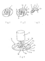
- this contact pad 1 is in one piece and was made by shrinking, then machining the slots.
- a contact pad 2 made according to the method of the invention is illustrated.
- the first step of the method consists in identifying the shape of an elementary piece 3 having no slot, which part is intended to be reproduced in a certain number of copies, these elementary pieces 3 then being intended to be assembled in such a way as to forming a disk-shaped pellet 2 having slots 4.
- the elementary part 3 is manufactured for example by sintering without additional machining.
- the slots 4 of the contact pad 2 are formed by two facing edges 4a, 4b respectively belonging to two adjacent elementary pieces 3a, 3b.
- the pellet 2 is constituted by four elementary pieces 3a, 3b, 3c, 3d such as that illustrated on FIG. figure 3 said pieces being assembled to form a whole pellet.
- each of the elementary pieces 3 is formed by a ring quarter 5 connected on a part of its outer circumference 6 by a beak-shaped part 7, this part 7 having a circular peripheral edge 8 forming the circular peripheral edge of the contact pad 2, a rectilinear inner edge 9 and an outer lateral edge 10.
- the rectilinear inner edge 9 of an elementary piece 3a forms with the outer rectilinear edge 10a of a adjacent part 3d an orthoradial slot 11.
- the lateral outer edge 10 of the elementary part 3a forms with the rectilinear inner edge 9a of an adjacent elementary piece 3b an orthoradial rectilinear slot 11a of the contact pad 2.
- said elementary part After manufacture of the elementary part for example by sintering, said elementary part is calibrated, then annealed, in order to give the material of said part the expected physicochemical properties of the contact material.
- the piece thus manufactured can be deburred by industrial means (for example by passing the barrel).
- the contact is then reconstituted by final assembly of the various elementary parts and fixing of this assembly by a solder 12 on a contact support 13.
- this elementary part being smaller in size than the final pellet, the means of implementation, for example comprising a pelletizing press, are reduced and require less investment.
- the steps for calibrating and assembling the elementary shapes can be performed simultaneously with the aid of a shrinking piece 14, ensuring the mechanical strength of the contact, a solder 15 solidarizing the contact pad 2 to the contact support 13.
- the manufacturing method according to the invention applies in particular to vacuum interrupters of circuit breakers using the so-called axial magnetic field cleavage technique, as shown in FIG. figure 6 , or radial magnetic field as shown on the figure 7 , the slots 4 being oriented differently on the contact pad 2 according to the cutting technique used.
- the invention is also applicable to similar contacts having slots belonging to electrical switching devices. According to the example of the bulb illustrated on the figure 6 , the slots 16 are radial, while according to the embodiment of the bulb illustrated on the figure 7 the slots 17 are orthoradial.
- the number of segments constituting the pellet is at least two, the maximum limitation being determined by the technological limits of elaboration.
- the method of manufacturing contact pads according to the invention is applicable to any pad intended for the manufacture of contacts comprising slots for switches, circuit breakers, contactors with vacuum technology or other, in the fields of the average , low or high voltage, whatever its destination, from the moment when the pellet can be segmented into several elementary forms without any slot involving mechanical embrittlement of the piece to be sintered.
- the invention can be used for contact pads consisting of contact material compositions for cutting short circuit currents (circuit breakers) or load currents (switches), occasionally or with high electrical endurance (contactors), for example contacts made of Cu-Cr with a mass percentage of chromium of between 10% and 60%.
- a method of manufacturing a contact pad which is particularly economical, has a reduced implementation means. Indeed, the elementary part being of smaller dimensions than the final pellet, the implementation means used (for example a pelletizing press) are reduced and require less investment.
- the invention also makes it possible to produce complex slot shapes that can hardly be obtained by machining. In addition, this type of elemental petal is easily achievable directly to the sides by metallurgy powders, this being more difficult for whole pellets because of the slots.
- the invention is not limited to the embodiments described and illustrated which have been given by way of example.
Landscapes
- Manufacture Of Switches (AREA)
- Powder Metallurgy (AREA)
Claims (3)
- Kontaktplättchen bestehend aus mindestens zwei voneinander unabhängigen Elementen (3a, 3b, 3c, 3d), welche Elemente keine Schlitze (4) aufweisen und reproduzierbar sind, um nach entsprechender Verbindung der Elemente ein Kontaktplättchen (2) gewünschter Endform zu bilden, wobei in dem genannten Kontaktplättchen Schlitze ausgebildet sind, von denen jeder einzelne Schlitz (4) durch zwei einander gegenüberliegende Ränder (4a, 4b) gebildet wird, die zu zwei aneinandergrenzenden Grundelementen gehören, dadurch gekennzeichnet, dass jedes Grundelement aus einem Viertelring (5) besteht, der in einem Teilabschnitt seiner Umfangslinie (6) mit einem schnabelförmigen Bereich (7) verbunden ist, welcher schnabelförmige Bereich (7) einen kreisbogenförmigen Außenrand (8), der den umlaufenden Rand des Kontaktplättchens (2) bildet, einen geradlinigen Innenrand (9), der dazu dient, mit dem seitlichen Außenrand (10a) eines angrenzenden Grundelements (3d) einen orthoradialen geradlinigen Schlitz (11) des Kontaktplättchens (2) zu bilden, sowie einen seitlichen Außenrand (10) aufweist, der dazu dient, mit dem geradlinigen Innenrand (9a) eines angrenzenden Grundelements (3b) einen zweiten orthoradialen Schlitz (11) zu bilden, wobei das genannte Kontaktplättchen durch abschließende Verbindung der einzelnen Grundelemente und Befestigung der so gebildeten Anordnung durch Auflöten 12 auf einen Kontaktträger hergestellt wird und die genannte Lötverbindung zwischen die Viertelringe und den genannten Kontaktträger eingebracht wird.
- Elektrisches Schaltgerät mit mindestens einem Kontaktplättchen nach Anspruch 1.
- Vakuum-Schaltrohr mit mindestens einem Kontaktplättchen (2) nach Anspruch 1.
Applications Claiming Priority (1)
| Application Number | Priority Date | Filing Date | Title |
|---|---|---|---|
| FR0707166A FR2922355B1 (fr) | 2007-10-12 | 2007-10-12 | Procede de fabrication de pastilles de contacts pour un appareil de coupure electrique et pastille de contact obtenue selon ce procede |
Publications (2)
| Publication Number | Publication Date |
|---|---|
| EP2048675A1 EP2048675A1 (de) | 2009-04-15 |
| EP2048675B1 true EP2048675B1 (de) | 2010-08-25 |
Family
ID=39386438
Family Applications (1)
| Application Number | Title | Priority Date | Filing Date |
|---|---|---|---|
| EP08354064A Active EP2048675B1 (de) | 2007-10-12 | 2008-09-29 | Herstellungsverfahren von Knöpfen für ein elektrisches Schneidegerät und nach diesem Verfahren erhaltener Knopf |
Country Status (5)
| Country | Link |
|---|---|
| EP (1) | EP2048675B1 (de) |
| CN (1) | CN101409163B (de) |
| AT (1) | ATE479192T1 (de) |
| DE (1) | DE602008002299D1 (de) |
| FR (1) | FR2922355B1 (de) |
Families Citing this family (1)
| Publication number | Priority date | Publication date | Assignee | Title |
|---|---|---|---|---|
| FR2969367B1 (fr) * | 2010-12-17 | 2013-04-26 | Schneider Electric Ind Sas | Appareil de coupure electrique |
Family Cites Families (4)
| Publication number | Priority date | Publication date | Assignee | Title |
|---|---|---|---|---|
| DE2454157C3 (de) * | 1974-11-14 | 1979-03-15 | Siemens Ag, 1000 Berlin Und 8000 Muenchen | Vakuumschaltrohr |
| DE3422949A1 (de) * | 1984-06-19 | 1985-12-19 | Siemens AG, 1000 Berlin und 8000 München | Vakuumschaltroehre mit einer spule zum erzeugen eines magnetfeldes |
| JPS61126720A (ja) * | 1984-11-22 | 1986-06-14 | 株式会社日立製作所 | 真空遮断器 |
| JP2002334641A (ja) * | 2001-05-09 | 2002-11-22 | Meidensha Corp | 真空遮断器の電極及びその製造方法 |
-
2007
- 2007-10-12 FR FR0707166A patent/FR2922355B1/fr not_active Expired - Fee Related
-
2008
- 2008-09-29 DE DE602008002299T patent/DE602008002299D1/de active Active
- 2008-09-29 AT AT08354064T patent/ATE479192T1/de active
- 2008-09-29 EP EP08354064A patent/EP2048675B1/de active Active
- 2008-10-10 CN CN200810169870.6A patent/CN101409163B/zh not_active Expired - Fee Related
Also Published As
| Publication number | Publication date |
|---|---|
| EP2048675A1 (de) | 2009-04-15 |
| ATE479192T1 (de) | 2010-09-15 |
| FR2922355B1 (fr) | 2009-12-04 |
| DE602008002299D1 (de) | 2010-10-07 |
| CN101409163A (zh) | 2009-04-15 |
| CN101409163B (zh) | 2013-05-29 |
| FR2922355A1 (fr) | 2009-04-17 |
Similar Documents
| Publication | Publication Date | Title |
|---|---|---|
| EP2261940B1 (de) | Wickung für einen Vakuumschalterkontakt mit erhöhter Festigkeit, Vakuumschalter und Schalteinrichtung, insbesondere Generator-Schutzschalter | |
| EP2867912B1 (de) | Elektrischer schalter zur herstellung eines schnellbetätigungsschutzschalters | |
| EP1445829B1 (de) | Subreflektor für Cassegrain-Mikrowellenantenne | |
| EP2120242B1 (de) | Elektrischer Trennschalter für Mittel- und Hochspannung | |
| FR2918509A1 (fr) | Traversee metal - materiau de fixation | |
| EP2048675B1 (de) | Herstellungsverfahren von Knöpfen für ein elektrisches Schneidegerät und nach diesem Verfahren erhaltener Knopf | |
| FR2828760A1 (fr) | Ensemble a lames pour disjoncteur, et procede d'interruption de circuit | |
| EP0807945B1 (de) | Hochspannungsschalter mit Einschaltwiderstand | |
| EP3132460B1 (de) | Drehbogenschutzschalter mit einer feldspule mit hohem widerstand | |
| EP1152445B1 (de) | Vakuumröhre für elektrisches Schutzgerät wie z.B. einen Schalter oder einen Lastschalter | |
| EP0715324B1 (de) | Elektrischer Vakuumschalter | |
| EP3035363B1 (de) | Lichtbogen-schaltkammer für einen leistungsschalter, und leistungsschalter, der eine solche kammer umfasst | |
| EP3251140B1 (de) | Schutzschalter mit ausziehbarer auslassabdeckung | |
| EP4022661A1 (de) | Pyrotechnischer schalter | |
| EP4095878B1 (de) | Unterbrechungssystem eines elektrischen geräts | |
| EP4654238A1 (de) | Elektrische schaltkontaktanordnung | |
| EP4020514B1 (de) | Elektrischer unterbrechungskontakt | |
| FR3155945A1 (fr) | Tige de conduction de courant électrique pour ampoule à vide | |
| EP4006939A1 (de) | Mittelspannungs-vakuumröhrenkontakt mit verbesserter lichtbogenunterbrechung und entsprechende vakuumröhre | |
| EP2827352B1 (de) | Schutzschalter und Herstellungsverfahren eines Schutzschalters | |
| EP4064309B1 (de) | System zur abschaltung eines elektrischen geräts | |
| FR3161795A1 (fr) | Dispositif de coupure électrique | |
| FR3147662A1 (fr) | Coupe-circuit pyrotechnique | |
| EP2402970A1 (de) | Unterbrechungskammer eines Schutzschalters für Hoch- und Mittelspannung mit reduzierter Bedienungsenergie und kleineren Abmessungen | |
| FR2613125A1 (fr) | Piece de contact d'un disjoncteur miniature et procede de fabrication d'une telle piece a partir d'une bande bimetallique |
Legal Events
| Date | Code | Title | Description |
|---|---|---|---|
| PUAI | Public reference made under article 153(3) epc to a published international application that has entered the european phase |
Free format text: ORIGINAL CODE: 0009012 |
|
| AK | Designated contracting states |
Kind code of ref document: A1 Designated state(s): AT BE BG CH CY CZ DE DK EE ES FI FR GB GR HR HU IE IS IT LI LT LU LV MC MT NL NO PL PT RO SE SI SK TR |
|
| AX | Request for extension of the european patent |
Extension state: AL BA MK RS |
|
| 17P | Request for examination filed |
Effective date: 20090427 |
|
| 17Q | First examination report despatched |
Effective date: 20090603 |
|
| AKX | Designation fees paid |
Designated state(s): AT BE BG CH CY CZ DE DK EE ES FI FR GB GR HR HU IE IS IT LI LT LU LV MC MT NL NO PL PT RO SE SI SK TR |
|
| GRAP | Despatch of communication of intention to grant a patent |
Free format text: ORIGINAL CODE: EPIDOSNIGR1 |
|
| RIN1 | Information on inventor provided before grant (corrected) |
Inventor name: GUILLET, DENIS Inventor name: CARDOLETTI, OLIVIER Inventor name: HENON, ALBIN Inventor name: NICOLLE, CYRIL |
|
| GRAS | Grant fee paid |
Free format text: ORIGINAL CODE: EPIDOSNIGR3 |
|
| GRAA | (expected) grant |
Free format text: ORIGINAL CODE: 0009210 |
|
| AK | Designated contracting states |
Kind code of ref document: B1 Designated state(s): AT BE BG CH CY CZ DE DK EE ES FI FR GB GR HR HU IE IS IT LI LT LU LV MC MT NL NO PL PT RO SE SI SK TR |
|
| REG | Reference to a national code |
Ref country code: GB Ref legal event code: FG4D Free format text: NOT ENGLISH |
|
| REG | Reference to a national code |
Ref country code: CH Ref legal event code: EP |
|
| REG | Reference to a national code |
Ref country code: IE Ref legal event code: FG4D Free format text: LANGUAGE OF EP DOCUMENT: FRENCH |
|
| REF | Corresponds to: |
Ref document number: 602008002299 Country of ref document: DE Date of ref document: 20101007 Kind code of ref document: P |
|
| REG | Reference to a national code |
Ref country code: NL Ref legal event code: VDEP Effective date: 20100825 |
|
| LTIE | Lt: invalidation of european patent or patent extension |
Effective date: 20100825 |
|
| PG25 | Lapsed in a contracting state [announced via postgrant information from national office to epo] |
Ref country code: NO Free format text: LAPSE BECAUSE OF FAILURE TO SUBMIT A TRANSLATION OF THE DESCRIPTION OR TO PAY THE FEE WITHIN THE PRESCRIBED TIME-LIMIT Effective date: 20101125 Ref country code: LT Free format text: LAPSE BECAUSE OF FAILURE TO SUBMIT A TRANSLATION OF THE DESCRIPTION OR TO PAY THE FEE WITHIN THE PRESCRIBED TIME-LIMIT Effective date: 20100825 Ref country code: FI Free format text: LAPSE BECAUSE OF FAILURE TO SUBMIT A TRANSLATION OF THE DESCRIPTION OR TO PAY THE FEE WITHIN THE PRESCRIBED TIME-LIMIT Effective date: 20100825 |
|
| PG25 | Lapsed in a contracting state [announced via postgrant information from national office to epo] |
Ref country code: BG Free format text: LAPSE BECAUSE OF FAILURE TO SUBMIT A TRANSLATION OF THE DESCRIPTION OR TO PAY THE FEE WITHIN THE PRESCRIBED TIME-LIMIT Effective date: 20101125 Ref country code: PL Free format text: LAPSE BECAUSE OF FAILURE TO SUBMIT A TRANSLATION OF THE DESCRIPTION OR TO PAY THE FEE WITHIN THE PRESCRIBED TIME-LIMIT Effective date: 20100825 Ref country code: CY Free format text: LAPSE BECAUSE OF FAILURE TO SUBMIT A TRANSLATION OF THE DESCRIPTION OR TO PAY THE FEE WITHIN THE PRESCRIBED TIME-LIMIT Effective date: 20100825 Ref country code: IS Free format text: LAPSE BECAUSE OF FAILURE TO SUBMIT A TRANSLATION OF THE DESCRIPTION OR TO PAY THE FEE WITHIN THE PRESCRIBED TIME-LIMIT Effective date: 20101225 Ref country code: SI Free format text: LAPSE BECAUSE OF FAILURE TO SUBMIT A TRANSLATION OF THE DESCRIPTION OR TO PAY THE FEE WITHIN THE PRESCRIBED TIME-LIMIT Effective date: 20100825 Ref country code: HR Free format text: LAPSE BECAUSE OF FAILURE TO SUBMIT A TRANSLATION OF THE DESCRIPTION OR TO PAY THE FEE WITHIN THE PRESCRIBED TIME-LIMIT Effective date: 20100825 |
|
| REG | Reference to a national code |
Ref country code: IE Ref legal event code: FD4D |
|
| BERE | Be: lapsed |
Owner name: SCHNEIDER ELECTRIC INDUSTRIES SAS Effective date: 20100930 |
|
| PG25 | Lapsed in a contracting state [announced via postgrant information from national office to epo] |
Ref country code: GR Free format text: LAPSE BECAUSE OF FAILURE TO SUBMIT A TRANSLATION OF THE DESCRIPTION OR TO PAY THE FEE WITHIN THE PRESCRIBED TIME-LIMIT Effective date: 20101126 Ref country code: NL Free format text: LAPSE BECAUSE OF FAILURE TO SUBMIT A TRANSLATION OF THE DESCRIPTION OR TO PAY THE FEE WITHIN THE PRESCRIBED TIME-LIMIT Effective date: 20100825 Ref country code: SE Free format text: LAPSE BECAUSE OF FAILURE TO SUBMIT A TRANSLATION OF THE DESCRIPTION OR TO PAY THE FEE WITHIN THE PRESCRIBED TIME-LIMIT Effective date: 20100825 Ref country code: LV Free format text: LAPSE BECAUSE OF FAILURE TO SUBMIT A TRANSLATION OF THE DESCRIPTION OR TO PAY THE FEE WITHIN THE PRESCRIBED TIME-LIMIT Effective date: 20100825 |
|
| PG25 | Lapsed in a contracting state [announced via postgrant information from national office to epo] |
Ref country code: IE Free format text: LAPSE BECAUSE OF FAILURE TO SUBMIT A TRANSLATION OF THE DESCRIPTION OR TO PAY THE FEE WITHIN THE PRESCRIBED TIME-LIMIT Effective date: 20100825 Ref country code: DK Free format text: LAPSE BECAUSE OF FAILURE TO SUBMIT A TRANSLATION OF THE DESCRIPTION OR TO PAY THE FEE WITHIN THE PRESCRIBED TIME-LIMIT Effective date: 20100825 Ref country code: MC Free format text: LAPSE BECAUSE OF NON-PAYMENT OF DUE FEES Effective date: 20100930 |
|
| PG25 | Lapsed in a contracting state [announced via postgrant information from national office to epo] |
Ref country code: SK Free format text: LAPSE BECAUSE OF FAILURE TO SUBMIT A TRANSLATION OF THE DESCRIPTION OR TO PAY THE FEE WITHIN THE PRESCRIBED TIME-LIMIT Effective date: 20100825 Ref country code: IT Free format text: LAPSE BECAUSE OF FAILURE TO SUBMIT A TRANSLATION OF THE DESCRIPTION OR TO PAY THE FEE WITHIN THE PRESCRIBED TIME-LIMIT Effective date: 20100825 Ref country code: RO Free format text: LAPSE BECAUSE OF FAILURE TO SUBMIT A TRANSLATION OF THE DESCRIPTION OR TO PAY THE FEE WITHIN THE PRESCRIBED TIME-LIMIT Effective date: 20100825 Ref country code: EE Free format text: LAPSE BECAUSE OF FAILURE TO SUBMIT A TRANSLATION OF THE DESCRIPTION OR TO PAY THE FEE WITHIN THE PRESCRIBED TIME-LIMIT Effective date: 20100825 Ref country code: CZ Free format text: LAPSE BECAUSE OF FAILURE TO SUBMIT A TRANSLATION OF THE DESCRIPTION OR TO PAY THE FEE WITHIN THE PRESCRIBED TIME-LIMIT Effective date: 20100825 |
|
| PG25 | Lapsed in a contracting state [announced via postgrant information from national office to epo] |
Ref country code: ES Free format text: LAPSE BECAUSE OF FAILURE TO SUBMIT A TRANSLATION OF THE DESCRIPTION OR TO PAY THE FEE WITHIN THE PRESCRIBED TIME-LIMIT Effective date: 20101206 |
|
| PLBE | No opposition filed within time limit |
Free format text: ORIGINAL CODE: 0009261 |
|
| STAA | Information on the status of an ep patent application or granted ep patent |
Free format text: STATUS: NO OPPOSITION FILED WITHIN TIME LIMIT |
|
| PG25 | Lapsed in a contracting state [announced via postgrant information from national office to epo] |
Ref country code: BE Free format text: LAPSE BECAUSE OF NON-PAYMENT OF DUE FEES Effective date: 20100930 |
|
| 26N | No opposition filed |
Effective date: 20110526 |
|
| REG | Reference to a national code |
Ref country code: DE Ref legal event code: R097 Ref document number: 602008002299 Country of ref document: DE Effective date: 20110526 |
|
| PG25 | Lapsed in a contracting state [announced via postgrant information from national office to epo] |
Ref country code: MT Free format text: LAPSE BECAUSE OF FAILURE TO SUBMIT A TRANSLATION OF THE DESCRIPTION OR TO PAY THE FEE WITHIN THE PRESCRIBED TIME-LIMIT Effective date: 20100825 |
|
| PG25 | Lapsed in a contracting state [announced via postgrant information from national office to epo] |
Ref country code: HU Free format text: LAPSE BECAUSE OF FAILURE TO SUBMIT A TRANSLATION OF THE DESCRIPTION OR TO PAY THE FEE WITHIN THE PRESCRIBED TIME-LIMIT Effective date: 20110226 Ref country code: LU Free format text: LAPSE BECAUSE OF NON-PAYMENT OF DUE FEES Effective date: 20100929 |
|
| PG25 | Lapsed in a contracting state [announced via postgrant information from national office to epo] |
Ref country code: TR Free format text: LAPSE BECAUSE OF FAILURE TO SUBMIT A TRANSLATION OF THE DESCRIPTION OR TO PAY THE FEE WITHIN THE PRESCRIBED TIME-LIMIT Effective date: 20100825 |
|
| GBPC | Gb: european patent ceased through non-payment of renewal fee |
Effective date: 20120929 |
|
| PG25 | Lapsed in a contracting state [announced via postgrant information from national office to epo] |
Ref country code: GB Free format text: LAPSE BECAUSE OF NON-PAYMENT OF DUE FEES Effective date: 20120929 Ref country code: PT Free format text: LAPSE BECAUSE OF NON-PAYMENT OF DUE FEES Effective date: 20100825 |
|
| REG | Reference to a national code |
Ref country code: FR Ref legal event code: PLFP Year of fee payment: 9 |
|
| PGFP | Annual fee paid to national office [announced via postgrant information from national office to epo] |
Ref country code: CH Payment date: 20160914 Year of fee payment: 9 |
|
| PGFP | Annual fee paid to national office [announced via postgrant information from national office to epo] |
Ref country code: AT Payment date: 20160826 Year of fee payment: 9 |
|
| REG | Reference to a national code |
Ref country code: FR Ref legal event code: PLFP Year of fee payment: 10 |
|
| REG | Reference to a national code |
Ref country code: CH Ref legal event code: PL |
|
| REG | Reference to a national code |
Ref country code: AT Ref legal event code: MM01 Ref document number: 479192 Country of ref document: AT Kind code of ref document: T Effective date: 20170929 |
|
| PG25 | Lapsed in a contracting state [announced via postgrant information from national office to epo] |
Ref country code: LI Free format text: LAPSE BECAUSE OF NON-PAYMENT OF DUE FEES Effective date: 20170930 Ref country code: CH Free format text: LAPSE BECAUSE OF NON-PAYMENT OF DUE FEES Effective date: 20170930 |
|
| PG25 | Lapsed in a contracting state [announced via postgrant information from national office to epo] |
Ref country code: AT Free format text: LAPSE BECAUSE OF NON-PAYMENT OF DUE FEES Effective date: 20170929 |
|
| REG | Reference to a national code |
Ref country code: FR Ref legal event code: PLFP Year of fee payment: 11 |
|
| PGFP | Annual fee paid to national office [announced via postgrant information from national office to epo] |
Ref country code: DE Payment date: 20250926 Year of fee payment: 18 |
|
| PGFP | Annual fee paid to national office [announced via postgrant information from national office to epo] |
Ref country code: FR Payment date: 20250925 Year of fee payment: 18 |