EP2048335A1 - Moteur à course de piston variable - Google Patents
Moteur à course de piston variable Download PDFInfo
- Publication number
- EP2048335A1 EP2048335A1 EP08016234A EP08016234A EP2048335A1 EP 2048335 A1 EP2048335 A1 EP 2048335A1 EP 08016234 A EP08016234 A EP 08016234A EP 08016234 A EP08016234 A EP 08016234A EP 2048335 A1 EP2048335 A1 EP 2048335A1
- Authority
- EP
- European Patent Office
- Prior art keywords
- crankshaft
- camshaft
- rotational shaft
- end portion
- timing
- Prior art date
- Legal status (The legal status is an assumption and is not a legal conclusion. Google has not performed a legal analysis and makes no representation as to the accuracy of the status listed.)
- Granted
Links
Images


Classifications
-
- F—MECHANICAL ENGINEERING; LIGHTING; HEATING; WEAPONS; BLASTING
- F02—COMBUSTION ENGINES; HOT-GAS OR COMBUSTION-PRODUCT ENGINE PLANTS
- F02B—INTERNAL-COMBUSTION PISTON ENGINES; COMBUSTION ENGINES IN GENERAL
- F02B41/00—Engines characterised by special means for improving conversion of heat or pressure energy into mechanical power
- F02B41/02—Engines with prolonged expansion
- F02B41/04—Engines with prolonged expansion in main cylinders
-
- F—MECHANICAL ENGINEERING; LIGHTING; HEATING; WEAPONS; BLASTING
- F02—COMBUSTION ENGINES; HOT-GAS OR COMBUSTION-PRODUCT ENGINE PLANTS
- F02B—INTERNAL-COMBUSTION PISTON ENGINES; COMBUSTION ENGINES IN GENERAL
- F02B75/00—Other engines
- F02B75/04—Engines with variable distances between pistons at top dead-centre positions and cylinder heads
- F02B75/048—Engines with variable distances between pistons at top dead-centre positions and cylinder heads by means of a variable crank stroke length
Definitions
- the present invention relates to a variable stroke engine in which a crankshaft, a camshaft constituting a part of a valve-operating system, and a rotational shaft having an eccentric shaft, are rotatably supported in a crankcase of an engine body so as to have axes parallel to one another, a connecting rod is connected, at one end portion thereof, to a piston by a piston pin, a control rod is connected, at one end portion thereof, to the eccentric shaft, the other end portion of the connecting rod and the other end portion of the control rod are linked to each other by a link member rotatably supported on the crankshaft, and a rotative power of the crankshaft is transmitted to the camshaft and the rotational shaft, respectively.
- variable stroke engine has already been known as disclosed in Japanese Patent Application Laid-open No. 2005-54685 and the like.
- a driving gear for transmitting a power to a camshaft side and a driving gear for transmitting a power to a rotational shaft side are mounted on a crankshaft in a manner that these driving gears are adjacent to each other in the axial direction. Accordingly, the bearing span of the crankshaft is increased.
- This structure poses an increase in the diameter of the crankshaft for the purpose of avoiding deformation and an increase in friction of the crankshaft due to deterioration of the bearing support rigidity.
- the present invention has been made in view of the above-described circumstance. It is an object of the present invention to provide a variable stroke engine having a reduced bearing span of a crankshaft, and thus being capable of preventing the bearing support rigidity from deteriorating while avoiding an increase in the diameter of the crankshaft.
- a variable stroke engine in which a crankshaft, a camshaft constituting a part of a valve-operating system, and a rotational shaft having an eccentric shaft, are rotatably supported in a crankcase of an engine body so as to have axes parallel to one another, a connecting rod is connected, at one end portion thereof, to a piston by a piston pin, a control rod is connected, at one end portion thereof, to the eccentric shaft, the other end portion of the connecting rod and the other end portion of the control rod are linked to each other by a link member rotatably supported on the crankshaft, and a rotative power of the crankshaft is transmitted to the camshaft and the rotational shaft, respectively, the variable stroke engine comprising: a timing driving wheel mounted on the crankshaft, and transmitting the rotative power to the camshaft, and a timing driven wheel mounted on the rotational shaft, and driven by the timing driving wheel.
- the timing driving wheel is mounted on the crankshaft so as to be shared for the power transmission from the crankshaft to the camshaft and for the power transmission from the crankshaft to the rotational shaft.
- This configuration makes it possible to reduce the bearing span of the crankshaft as compared with a conventional variable stroke engine having two driving gears mounted on a crankshaft so as to be adjacent to each other. Accordingly, the bearing support rigidity can be prevented from deteriorating while an increase in the diameter of the crankshaft is avoided.
- the timing driving wheel is a gear
- a driven gear meshing with the timing driving wheel is mounted on the camshaft
- the timing driven wheel is a gear meshing with the timing driving wheel
- addendum modifications of the timing driven wheel and the driven gear are set to be different from each other.
- the camshaft and the rotational shaft are disposed on the same side of a plane defined by the cylinder axis and the crankshaft axis.
- the camshaft and the rotational shaft are disposed on the same side of a plane defined by the cylinder axis and the crankshaft axis. This configuration makes it possible to make compact the entire engine by disposing the camshaft at a position close to the rotational shaft side while avoiding interference between the camshaft and the trajectory of motion of the link member.
- FIG. 1 and FIG. 2 show a first embodiment of the present invention.
- FIG. 1 is a vertical cross-sectional side view of an engine, and is a cross-sectional view taken along a line 1-1 in FIG. 2 .
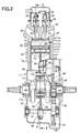
- FIG. 2 is a cross-sectional view taken along a line 2-2 in FIG. 1 .
- FIG. 3 is a vertical cross-sectional side view corresponding to FIG. 1 , and showing an engine of a second embodiment.
- This engine is an air-cooled single cylinder engine, which is used for working machines and the like, for example.
- An engine body 11 includes: a crankcase 12; a cylinder block 13 protruding upward from the crankcase 12; a cylinder head 14 joined to a head portion of the cylinder block 13; and a head cover 15 connected to the cylinder head 14.
- the crankcase 12 is mounted on engine heads of various operating machines, at a mounting face 12a on the lower surface of the crankcase 12.
- a crankshaft 17 is rotatably supported in the crankcase 12.
- the crankshaft 17 integrally has a pair of balance weights 17a and 17b, as well as a crank pin 17c which connects between the balance weights 17a and 17b.
- a cylinder bore 19 is formed in the cylinder block 13.
- a piston 18 is slidably fitted in the cylinder bore 19.
- a combustion chamber 20 is formed between the cylinder block 13 and the cylinder head 14, and a top portion of the piston 18 faces the combustion chamber 20.
- An intake port 21 and an exhaust port 22, both communicating with the combustion chamber 20, are formed in the cylinder head 14.
- an intake valve 23 for opening and closing the passage between the intake port 21 and the combustion chamber 20 as well as an exhaust valve 24 for opening and closing the passage between the exhaust port 22 and the combustion chamber 20 are disposed in the cylinder head 14 so as to be capable of performing the opening and closing operations.
- a valve-operating system 25 for driving the intake valve 23 and the exhaust valve 24 to be opened and closed includes a camshaft 26, an intake-side cam 27, an exhaust-side cam 28, an intake-side valve lifter 29, an exhaust-side valve lifter 30, an intake-side push rod 31, an exhaust-side push rod (not illustrated), an intake-side rocker arm 33, and an exhaust-side rocker arm 34.
- the camshaft 26 has an axis parallel to the crankshaft 17, and is rotatably supported in the crankcase 12.
- the intake-side and exhaust-side cams 27 and 28 are provided on the camshaft 26.
- the intake-side valve lifter 29 is operably supported in the cylinder block 13, and is in sliding contact with the intake-side cam 27.
- the exhaust-side valve lifter 30 is operably supported in the cylinder block 13, and is in sliding contact with the exhaust-side cam 28.
- the intake-side push rod 31 extends toward the head cover 15 while abutting, at the lower end thereof, on the intake-side valve lifter 29.
- the exhaust-side push rod extends toward the head cover 15 while abutting, at the lower end thereof, on the exhaust-side valve lifter 30.
- the intake-side rocker arm 33 is swingably supported in the cylinder head 14, while abutting, at one end thereof, on the intake valve 23 spring-biased in its closing direction. The upper end of the intake-side push rod 31 abuts on the other end of the intake-side rocker arm 33.
- the exhaust-side rocker arm 34 is swingably supported in the cylinder head 14, while abutting, at one end thereof, on the exhaust valve 24 spring-biased in its closing direction.
- the upper end of the exhaust-side push rod abuts on the other end of the exhaust-side rocker arm 34.
- An operating chamber 35 is formed in the cylinder block 13 and the cylinder head 14.
- the upper portions respectively of the intake-side and exhaust-side valve lifters 29 and 30 protrude into the operating chamber 35 from the lower portion of the operating chamber 35.
- the intake-side push rod 31 and the exhaust-side push rod are disposed in the operating chamber 35.
- a rotational shaft 37 having an eccentric shaft 38 is disposed on the opposite side of the axis of the crankshaft 17 from the camshaft 26.
- the rotational shaft 37 is rotatably supported in the crankcase 12 in a manner that the rotational shaft 37 is rotatable about its axis parallel to the crankshaft 17 and the camshaft 26.
- a connecting rod 41 is connected, at one end portion thereof, to the piston 18 by a piston pin 40, while a control rod 42 is connected, at one end portion thereof, to the eccentric shaft 38.
- the other end portions respectively of the connecting rod 41 and the control rod 42 are linked to each other by a link member 43 which is rotatably supported by the crank pin 17c of the crankshaft 17.
- the connecting rod 41, the link member 43, and the control rod 42 constitute a link mechanism 39.
- the link member 43 is formed to be in sliding contact with a half of the circumference of the crank pin 17c.
- a crank cap 44 is in sliding contact with the remaining half of the circumference of the crank pin 17c, and is fastened to the link member 43 with bolts 45, 45.
- the connecting rod 41 is rotatably connected, at the other end portion thereof, to one end portion of the link member 43 by a first pin 46.
- a circular shaft hole 47 is formed in the one end portion of the control rod 42, and the eccentric shaft 38 is fitted in the circular shaft hole 47 so as to be relatively slidable.
- the control rod 42 is rotatably connected, at the other end portion thereof, to the other end portion of the link member 43 by a second pin 48.
- a driving gear 49 is mounted on the crankshaft 17, and arranged at a position to the outer side, in the axial direction, of the balance weight 17b of the crankshaft 17.
- the driving gear 49 serves as a timing driving wheel for transmitting the rotative power to the camshaft 26 side.
- a first driven gear 50 meshing with the driving gear 49 is mounted on the camshaft 26.
- a second driven gear 51 meshing with the driving gear 49 and serving as a timing driven wheel is mounted on the rotational shaft 37.
- the first and second driven gears 50 and 51 are each formed to have an outside diameter which is twice as large as that of the driving gear 49.
- the width of the first driven gear 50 in the axial direction is set to be approximately half the width of the driving gear 49 in the axial direction
- the width of the second driven gear 51 in the axial direction is set to be substantially the same as the width of the driving gear 49 in the axial direction, in consideration of the fact that the load between the crankshaft 17 and the rotational shaft 37 is larger than that between the crankshaft 17 and the camshaft 26.
- addendum modifications respectively of the first driven gear 50 mounted on the camshaft 26 and of the second driven gear 51 mounted on the rotational shaft 37 are set to be different from each other.
- the link mechanism 39 operates in association with the rotation of the eccentric shaft 38 with a speed reduction ratio of 1/2 according to the rotation of the crankshaft 17, in a manner that the stroke of the piston 18 in the expansion stroke becomes larger than that in the compression stroke.
- a higher expansion work is achieved with the same intake volume of the air-fuel mixture, so that the cycle thermal efficiency is improved.
- the driving gear 49 for transmitting the rotative power to the camshaft 26 side is mounted on the crankshaft 17, while the second driven gear 51 meshing with the driving gear 49 is mounted on the rotational shaft 37.
- the driving gear 49 is mounted on the crankshaft 17 so as to be shared for the power transmission from the crankshaft 17 to the camshaft 26 and for the power transmission from the crankshaft 17 to the rotational shaft 37.
- the addendum modifications respectively of the first driven gear 50 mounted on the camshaft 26 and of the second driven gear 51 mounted on the rotational shaft 37 are set to be different from each other, the load applied to the camshaft 26 and the rotational shaft 37 is optimally distributed. Accordingly, the engine can be reduced in size by individually setting the distance between the crankshaft 17 and the camshaft 26 as well as the distance between the crankshaft 17 and the rotational shaft 37.
- FIG 3 shows the second embodiment of the present invention. Parts corresponding to those in the first embodiment are shown in FIG. 3 with the same reference numerals, and are not described in detail.
- the camshaft 26 is disposed on the opposite side of the axis of the crankshaft 17 from the rotational shaft 37.
- the camshaft 26 and a rotational shaft 37 are disposed on the same side of a plane defined by a cylinder axis C and the axis of the crankshaft 17.
- the intake-side valve lifter 29, the exhaust-side valve lifter 30, the intake-side push rod 31, and the exhaust-side push rod in the valve-operating system 25 are disposed on the opposite side from those in the first embodiment.
- the camshaft 26 it is possible to make the entire engine compact by disposing the camshaft 26 at a position close to the rotational shaft 37 side while avoiding interference between the camshaft 26 and the trajectory of the motion of the link member 43.
- a variable stroke engine has a crankshaft, a camshaft, and a rotational shaft, having an eccentric shaft, which are rotatably supported in a crankcase so as to have axes parallel to one another.
- a connecting rod is connected, at one end portion thereof, to a piston by a piston pin, and a control rod is connected, at one end portion thereof, to the eccentric shaft.
- the other end portion of the connecting rod and the other end portion of the control rod are linked to each other by a link member rotatably supported on the crankshaft.
- a rotative power of the crankshaft is transmitted to the camshaft and the rotational shaft, respectively.
- a timing driving wheel transmitting the rotative power to the camshaft side is mounted on the crankshaft, and a timing driven wheel driven by the timing driving wheel is mounted on the rotational shaft.
Applications Claiming Priority (1)
| Application Number | Priority Date | Filing Date | Title |
|---|---|---|---|
| JP2007265674A JP4922121B2 (ja) | 2007-10-11 | 2007-10-11 | ストローク可変エンジン |
Publications (2)
| Publication Number | Publication Date |
|---|---|
| EP2048335A1 true EP2048335A1 (fr) | 2009-04-15 |
| EP2048335B1 EP2048335B1 (fr) | 2011-02-16 |
Family
ID=39771178
Family Applications (1)
| Application Number | Title | Priority Date | Filing Date |
|---|---|---|---|
| EP08016234A Expired - Fee Related EP2048335B1 (fr) | 2007-10-11 | 2008-09-15 | Moteur à course de piston variable |
Country Status (5)
| Country | Link |
|---|---|
| US (1) | US8127739B2 (fr) |
| EP (1) | EP2048335B1 (fr) |
| JP (1) | JP4922121B2 (fr) |
| CN (1) | CN101408128B (fr) |
| DE (1) | DE602008004963D1 (fr) |
Cited By (1)
| Publication number | Priority date | Publication date | Assignee | Title |
|---|---|---|---|---|
| EP3246543A4 (fr) * | 2015-01-15 | 2017-12-27 | Nissan Motor Co., Ltd. | Mécanisme à piston et manivelle à double biellette pour moteur à combustion interne |
Families Citing this family (9)
| Publication number | Priority date | Publication date | Assignee | Title |
|---|---|---|---|---|
| FI121283B (fi) * | 2009-08-17 | 2010-09-15 | Aulis Pohjalainen | Moottorin sylinteripaineen säädin |
| US20130312698A1 (en) * | 2011-11-20 | 2013-11-28 | Nagesh Siddabasappa Mavinahally | Ms extended expansion engine |
| CN103185124B (zh) * | 2011-12-31 | 2016-06-08 | 沃德(天津)传动有限公司 | 一种减速机及其箱体 |
| US8671895B2 (en) | 2012-05-22 | 2014-03-18 | Michael Inden | Variable compression ratio apparatus with reciprocating piston mechanism with extended piston offset |
| JP2014034927A (ja) * | 2012-08-09 | 2014-02-24 | Honda Motor Co Ltd | 復リンク式の内燃機関 |
| DE102013021980A1 (de) * | 2013-12-20 | 2015-06-25 | Audi Ag | Koppelglied für einen Mehrgelenkskurbeltrieb sowie Mehrgelenkskurbeltrieb |
| US9334797B2 (en) * | 2014-05-15 | 2016-05-10 | Luis Alberto Velazquez | System for a mechanical conversion of an internal combustion engine of 4 strokes into 8 strokes |
| DE102016011392A1 (de) * | 2016-09-21 | 2018-03-22 | GM Global Technology Operations, LLC (n.d. Ges. d. Staates Delaware) | Brennkraftmaschine |
| JP7034195B2 (ja) * | 2020-03-18 | 2022-03-11 | 本田技研工業株式会社 | 内燃機関 |
Citations (3)
| Publication number | Priority date | Publication date | Assignee | Title |
|---|---|---|---|---|
| US2314789A (en) * | 1938-06-17 | 1943-03-23 | Jacobsen Edwin | Internal combustion engine |
| EP1347159A2 (fr) * | 2002-03-20 | 2003-09-24 | Honda Giken Kogyo Kabushiki Kaisha | Moteur à combustion |
| JP2007064011A (ja) * | 2005-08-29 | 2007-03-15 | Honda Motor Co Ltd | ストローク可変エンジン |
Family Cites Families (13)
| Publication number | Priority date | Publication date | Assignee | Title |
|---|---|---|---|---|
| US6170443B1 (en) * | 1998-09-11 | 2001-01-09 | Edward Mayer Halimi | Internal combustion engine with a single crankshaft and having opposed cylinders with opposed pistons |
| JP2000108704A (ja) * | 1998-10-06 | 2000-04-18 | Fuji Heavy Ind Ltd | 複合プラネタリギア装置およびそれを用いたセンターディファレンシャル装置 |
| JP3861583B2 (ja) * | 2000-08-14 | 2006-12-20 | 日産自動車株式会社 | 内燃機関のピストンクランク機構 |
| US6499453B1 (en) * | 2000-10-30 | 2002-12-31 | Tecumseh Products Company | Mid cam engine |
| JPWO2002041313A1 (ja) * | 2000-11-20 | 2004-03-25 | ソニー株式会社 | ディスクトレイの移動装置及びディスク記録及び/又は再生装置 |
| US7051344B2 (en) * | 2000-11-20 | 2006-05-23 | Sony Corporation | Disk tray moving device and disk recording and/or reproducing device |
| JP3882643B2 (ja) * | 2001-04-05 | 2007-02-21 | 日産自動車株式会社 | 内燃機関の可変圧縮比機構 |
| JP2003314237A (ja) * | 2002-04-17 | 2003-11-06 | Honda Motor Co Ltd | エンジン |
| JP2003314211A (ja) * | 2002-04-17 | 2003-11-06 | Honda Motor Co Ltd | ストローク可変エンジン |
| JP4057976B2 (ja) | 2003-08-05 | 2008-03-05 | 本田技研工業株式会社 | 圧縮比可変エンジン |
| US6857401B1 (en) * | 2004-01-09 | 2005-02-22 | Ford Global Technologies, Llc | Variable compression ratio sensing system for internal combustion engine |
| JP2005211142A (ja) * | 2004-01-27 | 2005-08-11 | Aisin Seiki Co Ltd | 角度調整装置 |
| JP2006250182A (ja) * | 2005-03-08 | 2006-09-21 | Jtekt Corp | 差動歯車装置 |
-
2007
- 2007-10-11 JP JP2007265674A patent/JP4922121B2/ja not_active Expired - Fee Related
-
2008
- 2008-09-12 CN CN2008102131083A patent/CN101408128B/zh not_active Expired - Fee Related
- 2008-09-15 EP EP08016234A patent/EP2048335B1/fr not_active Expired - Fee Related
- 2008-09-15 DE DE602008004963T patent/DE602008004963D1/de active Active
- 2008-10-10 US US12/249,524 patent/US8127739B2/en not_active Expired - Fee Related
Patent Citations (3)
| Publication number | Priority date | Publication date | Assignee | Title |
|---|---|---|---|---|
| US2314789A (en) * | 1938-06-17 | 1943-03-23 | Jacobsen Edwin | Internal combustion engine |
| EP1347159A2 (fr) * | 2002-03-20 | 2003-09-24 | Honda Giken Kogyo Kabushiki Kaisha | Moteur à combustion |
| JP2007064011A (ja) * | 2005-08-29 | 2007-03-15 | Honda Motor Co Ltd | ストローク可変エンジン |
Cited By (2)
| Publication number | Priority date | Publication date | Assignee | Title |
|---|---|---|---|---|
| EP3246543A4 (fr) * | 2015-01-15 | 2017-12-27 | Nissan Motor Co., Ltd. | Mécanisme à piston et manivelle à double biellette pour moteur à combustion interne |
| US10087833B2 (en) | 2015-01-15 | 2018-10-02 | Nissan Motor Co., Ltd. | Double-link piston crank mechanism for internal combustion engine |
Also Published As
| Publication number | Publication date |
|---|---|
| EP2048335B1 (fr) | 2011-02-16 |
| US8127739B2 (en) | 2012-03-06 |
| DE602008004963D1 (de) | 2011-03-31 |
| JP2009092036A (ja) | 2009-04-30 |
| CN101408128A (zh) | 2009-04-15 |
| CN101408128B (zh) | 2011-06-08 |
| JP4922121B2 (ja) | 2012-04-25 |
| US20090095262A1 (en) | 2009-04-16 |
Similar Documents
| Publication | Publication Date | Title |
|---|---|---|
| EP2048335B1 (fr) | Moteur à course de piston variable | |
| EP2048336B1 (fr) | Moteur avec piston de course variable | |
| JP5105130B2 (ja) | 内燃機関の可変動弁装置 | |
| EP2655814B1 (fr) | Poussoir de soupape à galet antirotation | |
| US7305938B2 (en) | Stroke-variable engine | |
| JP2007064011A (ja) | ストローク可変エンジン | |
| US6953015B2 (en) | Engine | |
| US20090241873A1 (en) | Variable valve-operating system for internal combustion engine | |
| US8161922B2 (en) | Link type variable stroke engine | |
| EP2136049B1 (fr) | Moteur à piston de course variable | |
| JP2007205299A (ja) | 内燃機関のシリンダヘッド | |
| JP2592964B2 (ja) | エンジンの動弁装置 | |
| JP4459135B2 (ja) | ストローク可変エンジン | |
| JP6301757B2 (ja) | 内燃機関 | |
| JP2004052707A (ja) | エンジン | |
| JP2007205329A (ja) | 内燃機関の可変動弁機構 | |
| JP2007132248A (ja) | 可変動弁機構 | |
| JP2007205277A (ja) | 内燃機関の可変動弁機構 | |
| JP2007278089A (ja) | 内燃機関の可変動弁機構 | |
| JP2007278079A (ja) | 内燃機関の可変動弁機構 |
Legal Events
| Date | Code | Title | Description |
|---|---|---|---|
| PUAI | Public reference made under article 153(3) epc to a published international application that has entered the european phase |
Free format text: ORIGINAL CODE: 0009012 |
|
| 17P | Request for examination filed |
Effective date: 20080915 |
|
| AK | Designated contracting states |
Kind code of ref document: A1 Designated state(s): AT BE BG CH CY CZ DE DK EE ES FI FR GB GR HR HU IE IS IT LI LT LU LV MC MT NL NO PL PT RO SE SI SK TR |
|
| AX | Request for extension of the european patent |
Extension state: AL BA MK RS |
|
| AKX | Designation fees paid |
Designated state(s): DE FR GB IT |
|
| GRAP | Despatch of communication of intention to grant a patent |
Free format text: ORIGINAL CODE: EPIDOSNIGR1 |
|
| GRAS | Grant fee paid |
Free format text: ORIGINAL CODE: EPIDOSNIGR3 |
|
| GRAA | (expected) grant |
Free format text: ORIGINAL CODE: 0009210 |
|
| AK | Designated contracting states |
Kind code of ref document: B1 Designated state(s): DE FR GB IT |
|
| REG | Reference to a national code |
Ref country code: GB Ref legal event code: FG4D |
|
| REF | Corresponds to: |
Ref document number: 602008004963 Country of ref document: DE Date of ref document: 20110331 Kind code of ref document: P |
|
| REG | Reference to a national code |
Ref country code: DE Ref legal event code: R096 Ref document number: 602008004963 Country of ref document: DE Effective date: 20110331 |
|
| PLBE | No opposition filed within time limit |
Free format text: ORIGINAL CODE: 0009261 |
|
| STAA | Information on the status of an ep patent application or granted ep patent |
Free format text: STATUS: NO OPPOSITION FILED WITHIN TIME LIMIT |
|
| 26N | No opposition filed |
Effective date: 20111117 |
|
| REG | Reference to a national code |
Ref country code: DE Ref legal event code: R097 Ref document number: 602008004963 Country of ref document: DE Effective date: 20111117 |
|
| REG | Reference to a national code |
Ref country code: FR Ref legal event code: PLFP Year of fee payment: 8 |
|
| PGFP | Annual fee paid to national office [announced via postgrant information from national office to epo] |
Ref country code: GB Payment date: 20150909 Year of fee payment: 8 |
|
| PGFP | Annual fee paid to national office [announced via postgrant information from national office to epo] |
Ref country code: FR Payment date: 20150629 Year of fee payment: 8 |
|
| PGFP | Annual fee paid to national office [announced via postgrant information from national office to epo] |
Ref country code: IT Payment date: 20150925 Year of fee payment: 8 |
|
| GBPC | Gb: european patent ceased through non-payment of renewal fee |
Effective date: 20160915 |
|
| REG | Reference to a national code |
Ref country code: FR Ref legal event code: ST Effective date: 20170531 |
|
| PG25 | Lapsed in a contracting state [announced via postgrant information from national office to epo] |
Ref country code: GB Free format text: LAPSE BECAUSE OF NON-PAYMENT OF DUE FEES Effective date: 20160915 Ref country code: FR Free format text: LAPSE BECAUSE OF NON-PAYMENT OF DUE FEES Effective date: 20160930 |
|
| PG25 | Lapsed in a contracting state [announced via postgrant information from national office to epo] |
Ref country code: IT Free format text: LAPSE BECAUSE OF NON-PAYMENT OF DUE FEES Effective date: 20160915 |
|
| PGFP | Annual fee paid to national office [announced via postgrant information from national office to epo] |
Ref country code: DE Payment date: 20170912 Year of fee payment: 10 |
|
| REG | Reference to a national code |
Ref country code: DE Ref legal event code: R119 Ref document number: 602008004963 Country of ref document: DE |
|
| PG25 | Lapsed in a contracting state [announced via postgrant information from national office to epo] |
Ref country code: DE Free format text: LAPSE BECAUSE OF NON-PAYMENT OF DUE FEES Effective date: 20190402 |