EP2048290A2 - Coupling device with semi-automatic locking for the detachable coupling of an implement to a utility vehicle - Google Patents
Coupling device with semi-automatic locking for the detachable coupling of an implement to a utility vehicle Download PDFInfo
- Publication number
- EP2048290A2 EP2048290A2 EP08017346A EP08017346A EP2048290A2 EP 2048290 A2 EP2048290 A2 EP 2048290A2 EP 08017346 A EP08017346 A EP 08017346A EP 08017346 A EP08017346 A EP 08017346A EP 2048290 A2 EP2048290 A2 EP 2048290A2
- Authority
- EP
- European Patent Office
- Prior art keywords
- coupling
- bracket
- securing
- locking
- utility vehicle
- Prior art date
- Legal status (The legal status is an assumption and is not a legal conclusion. Google has not performed a legal analysis and makes no representation as to the accuracy of the status listed.)
- Granted
Links
Images








Classifications
-
- E—FIXED CONSTRUCTIONS
- E02—HYDRAULIC ENGINEERING; FOUNDATIONS; SOIL SHIFTING
- E02F—DREDGING; SOIL-SHIFTING
- E02F3/00—Dredgers; Soil-shifting machines
- E02F3/04—Dredgers; Soil-shifting machines mechanically-driven
- E02F3/627—Devices to connect beams or arms to tractors or similar self-propelled machines, e.g. drives therefor
-
- A—HUMAN NECESSITIES
- A01—AGRICULTURE; FORESTRY; ANIMAL HUSBANDRY; HUNTING; TRAPPING; FISHING
- A01D—HARVESTING; MOWING
- A01D87/00—Loaders for hay or like field crops
- A01D87/0053—Tractor-mounted loaders
- A01D87/0069—Tractor-mounted loaders mounted on the tractor but having their own lifting device
- A01D87/0076—Front loaders
-
- B—PERFORMING OPERATIONS; TRANSPORTING
- B62—LAND VEHICLES FOR TRAVELLING OTHERWISE THAN ON RAILS
- B62D—MOTOR VEHICLES; TRAILERS
- B62D49/00—Tractors
- B62D49/02—Tractors modified to take lifting devices
-
- E—FIXED CONSTRUCTIONS
- E02—HYDRAULIC ENGINEERING; FOUNDATIONS; SOIL SHIFTING
- E02F—DREDGING; SOIL-SHIFTING
- E02F3/00—Dredgers; Soil-shifting machines
- E02F3/04—Dredgers; Soil-shifting machines mechanically-driven
- E02F3/627—Devices to connect beams or arms to tractors or similar self-propelled machines, e.g. drives therefor
- E02F3/6273—Devices to connect beams or arms to tractors or similar self-propelled machines, e.g. drives therefor using legs to support the beams or arms on the ground during the connecting process
Definitions
- the present invention relates to a coupling device for the detachable coupling of a working device, in particular of a front loader, on a utility vehicle, in particular on an agricultural tractor in accordance with the preamble of Claim 1.
- Such a device is known, for example, from DE 32 29 947 A1 .
- a first mounting part is secured to a tractor, and a second mounting part is coupled to the front loader rocker arm.
- a locking device is provided in the form of a locking block, which has flattened surfaces which are adapted to co-operate with the hook-shaped jaws under the action of a spring element to lock the mounting parts together.
- a hand lever is provided, by means of which the locking block can be moved to an unlocked position. The locking block can be moved to its locking position by the engagement of the hand lever with a corresponding engagement projection carried by the loader rocker arm.
- a front loader is known from DE 36 30 976 A1 which can be coupled by means of spar ends of its loader rocker arms to mounting brackets on a tractor.
- a locking device in the form of a latch is subjected to pre-tension into a locked position by a locking spring.
- An actuation lever is provided to unlock the latch, which is fitted with a slotted plate, which has a guide slot into which a bolt of the latch engages.
- the latch can be moved by actuating the actuation lever into an unlocked position.
- the latch is fixed in the unlocked position.
- a device for the detachable coupling of a working device, in particular a loader rocker arm, to a carrier vehicle.
- a locking arrangement is provided in this case between the loader rocker arm and a mount-on bracket of a carrier vehicle, which consists of a moveable bolt element which is arranged on a carrier bracket of the working device (the loader rocker arm), and which acts on a stop on the carrying bracket of the carrying vehicle, such that the carrying bracket of the working device and the carrying vehicle can be locked to one another.
- an actuating lever is spring biased into a position in which the bolt element locks the working device to the carrying vehicle.
- An engagement device is also provided, by means of which the bolt element, after the release of the device, is held in its unlocked position against the effect of the spring biasing, this engagement device being released when that the carrying brackets of the working device and of the carrying vehicle are brought into contact with one another.
- the object of the present invention is to provide a securing device which reliably prevents unintentional unlocking of the locking device or unintentional raising of the working device from the utility vehicle.
- This is intended to be associated with easy handling, such that the locking or unlocking and coupling and uncoupling respectively of the working device and of the utility vehicle can be carried out in an easy manner.
- the unlocked position can be adopted again immediately after the uncoupling, in order to be ready for the next coupling procedure.
- an additional securing element is provided, by means of which an unintentional unlocking of the locking element can be prevented.
- the locking element can be moved together with the securing element into the unlocked position, without a separate uncoupling of the securing element being required.
- a type of semi-automatic arrangement is produced, such that, after uncoupling, the locking device again passes into a state in which it is ready for the next coupling procedure.
- the kinematic arrangement according to the invention makes the situation easier, in that by the actuating of a single actuation element both the locking element passes into an unlocked position and the securing element passes, beforehand or simultaneously, out of a locked position into an unlocked position.
- the locking element In the locked position, the locking element is located advantageously in a position in which a locking surface is in contact with a locking contour of the utility vehicle coupling bracket, such that a movement against the relative coupling movement between the working device coupling bracket and the utility vehicle coupling bracket is prevented by a positive fit connection.
- the present embodiment example relates, according to Fig. 1 , to a tractor 20, which is intended to be coupled to a front loader rocker arm 1.
- the front loader rocker arm 1 is secured by means of a coupling device 4 to a coupling device 3 on the tractor.
- the coupling device 3 is secured firmly to the vehicle or to a vehicle frame 2 of the vehicle.
- the coupling device on the front loader 1, referred to hereinafter as the coupling tower 4, when coupled to the vehicle, is mechanically connected to the coupling device of the vehicle, referred to hereinafter as the mount-on bracket 3.
- Fig. 2 shows the two components in the coupled position.
- the remainder of the front loader rocker arm 1 has been omitted. This would be connected to the left side, in Fig. 2a , of the coupling tower 4, wherein the individual components are securely connected by bolts, which are guided through the holes 4a to 4c which can be identified there.
- the coupling tower 4 has two carrier parts 5 (see Fig. 2a ), which are designed as identical and are held at a predetermined distance from one another by a spacer plate 5d, such as can be seen for example in Fig. 2c .
- the spacer plate 5d is designed essentially in the form of an inverted Y.
- the two carrier parts 5 can be welded to one another by means of the spacer plate 5d.
- Inside the two carrier parts 5 are further components which are provided for locking the front loader to the vehicle.
- a mounting bolt 5b is provided, which is mounted in two holes coaxial to one another, provided in the carrier parts 5. The function of the mounting bolts 5b will be described later.
- in the lower region of the carrier parts 5 holes are provided, aligned in each case coaxially to one another, which form a rotation axis A (see Fig. 2b, c ), the function of which is described below.
- Figs. 2b and 2c two curved discs are provided, aligned parallel to one another, which serve as locking elements 6, described later, in the form of contoured plates.
- the two locking elements 6 are mounted so as to be rotatable about the axis A, as can be seen from Fig. 2b .
- the axis A is provided by a bolt, which is mounted in holes in the carrier parts 5.
- the locking element 6 has a passage aperture 6a, which can be seen, for example, in Fig. 3 as well as in Figures 4 to 11 .
- the passage aperture is formed as a type of elongated slot.
- the locking element 6 in the present embodiment example is designed as a curved disc in the form of a segment of a circle. In this situation the circle-segment-related outer circumference section of the circle segment corresponds to the outer radius of a circle. According to a further embodiment, however, the outer circumference can also have a changing curvature, in order, for example, to strengthen the clamping effect with the mount-on bracket, as described later.
- a hand lever 7 is provided in the carrier part 5, which is mounted such as to rotate about an axle B (see Fig. 2b, c ).
- the hand lever 7 is provided at its end opposite the handle with a sheet metal segment, on which a carrier bolt 7a is located, which extends perpendicular to this (see Figs. 2c , 4-9 ).
- a curved longitudinal hole 5a is provided in the carrier part 5, which lies within a radius about an axle B as the circle centre point (see Fig. 3 ).
- the passage aperture 6a in this situation has an aperture width which is greater than the diameter of the carrier bolt 7a.
- a securing element 8 is provided, such as can be seen, for example, in Fig. 2c , and in particular as an individual component in Figs. 13 and 14 .
- this is a contoured sheet, which is mounted so as to rotate about an axle C provided in the locking element 6 (see Figs. 3-9 ).
- the securing element 8 in the present embodiment example is shaped as a bar in the form of an inverted U. It consists of a middle part 8a, connected to which are two limbs 8b, angled essentially at right angles downwards in Figs. 13b and 14 respectively. Provided at the free end of the limbs 8b in each case is a hole 8c. Both holes 8c are aligned coaxially to one another. The mid-point of the two holes 8c lies on and defines an axis of rotation C (see Fig. 14 ), the function of which will be described later.
- a type of lug 8e Formed approximately in the middle of the limbs 8b is a type of lug 8e, in which in each case a further hole 8d is provided. Both holes 8d are likewise aligned coaxially to one another. The mid-point of the two holes 8d lies on and defines the axis of rotation E, the function of which is described later (see Fig. 14 ).
- a contour 8f is provided on the edge side opposite the lug 8e (see Fig. 13a ).
- the securing element 8 is arranged in such a way, and contoured in such a way, that it is in contact tangentially with its contour 8f on the carrier bolt 7a (see Figs. 4-9 ). The interaction of the contour 8f and the carrier bolt 7a is described later.
- a tensioning spring assembly 9 is mounted on the carrier part 5.
- the tensioning spring assembly 9 is mounted at one end such as to be rotatable about an axle D in the carrier part 5, and, in addition, is mounted at the other end such as to be rotatable about the axle E in the securing element 8.
- the mount-on bracket 3 is explained hereinafter in greater detail by reference to Fig. 12 .
- two mount-on brackets are provided, which in each case are located on one side of the vehicle. These are solid cast components, connected to the vehicle frame 2 by securing eyes 3 f, g, h and i.
- the mount-on bracket extends essentially perpendicular upwards and is designed in the upper third as curved in the direction of travel (see Fig. 1 ).
- Located at the upper end of the main body is a semicircular cut-out aperture 3a (see Fig. 12 ).
- the securing contour 3d has a contact surface 3dlrunning obliquely from below in Fig. 12 .
- the oblique contact surface 3d1 merges into a straight part 3d2.
- a shoulder part 3d3 Connected to the straight part, running at approximately a right angle is a shoulder part 3d3, which leads the securing contour 3d back again into the main body of the mount-on bracket 3.
- the coupling tower 4 is pivoted by means of the front loader's own hydraulics system, as can be seen in Fig. 10 .
- the front axle suspension is set to the lowest position, such that the front part of the vehicle and therefore the mount-on bracket 3 are lowered towards the front.
- the vehicle In the lowered state, the vehicle is moved, in the coupling position, into the mount-on bracket.
- the upper mounting bolt 5b of the carrier part 5 in this situation is centred and suspended in the cut-out aperture 3a in the mount-on bracket 3.
- the coupling tower 4 is then pivoted back in the direction of arrow X by means of the front loader's own hydraulics system.
- the locking element 6 can again pivot downwards, since the run-on contour 3b has only a limited wall thickness, as can be seen in particular in Fig. 12 . Due to the spring force of the spring assembly 9, the locking element 6 is pressed downwards, such that the locking surface 6c of the locking element 6 comes in contact with the locking contour 3e of the mount-on bracket 3, and the two parts lock with one another. Due to the spring force, the coupling position is set in the "locked" position, free of play, as represented in Fig. 4 .
- the securing element 8 is provided, which, when the coupling tower is raised at the securing contour 3d, comes in contact with the mount-on bracket 3, and so prevents raising. This can best be seen in Fig. 11 .
- the middle part 8a of the securing element 8 is located opposite the securing contour 3d of the mount-on bracket 3.
- the middle part 8a of the securing element 8 would come in contact with the securing contour 3d of the mount-on bracket 3 and prevent any further movement.
- a point to be particularly emphasised in this situation is that the securing element 8 is moved in such a way that it is not blocked by the securing contour 3d of the mount-on bracket 3 but is firstly pivoted away out of this region and is then moved upwards. At the upper end of the securing contour 3d, the securing element 8 is then again pivoted by the spring force in such a way that the securing element 8 remains in the "unlocked" position (see Fig. 9 ) even after the hand lever has been released and the front loader can again be coupled up.
- Fig. 4 the "locked" position is represented. In this position the carrier bolt 7a in the passage aperture 6a is in its lowest position. Due to the spring force of the tensioning spring assembly 9, the securing element 8 is pressed about the rotation axle C against the carrier bolt 7a. As already indicated, the rotation axle C is provided in the locking element 6. That is to say, upon a rotation of the locking element 6 in the clockwise direction, the rotation axle C likewise moves upwards on a circular trajectory about the rotation axle A of the locking element 6. In consequence, the securing element 8, which is joint-connected at the rotation axle C to the locking element 6, also moves in a coupled movement. In the "locked” position shown in Fig. 4 , the securing element 8 is located with its middle part 8a opposite the securing contour 3d of the mount-on bracket 3. To better understand, for the mount-on bracket 3 only the securing contour 3d is shown as a line.
- a position is represented in which the hand lever 7 has been pivoted by 10° in a clockwise direction.
- the carrier bolt 7a is no longer in its lowest position in the passage aperture 6a, but is now in its uppermost position.
- the locking element 6 in this situation has not yet moved.
- the securing element 8 has, however, already rotated somewhat anti-clockwise about the axle C, against the spring force of the tensioning spring assembly 9. The reason for this is that, due to the spring pre-tension, the securing element with its contour 8f is constantly in contact with the carrier bolt 7a. Due to the movement of the carrier bolt 7a and contact with the contour 8f, the securing element 8 can as a consequence be easily pivoted.
- the middle part 8a of the securing element 8 is still located opposite the securing contour 3d of the mount-on bracket 3, in the figure it is already pivoted somewhat further to the left.
- a position is represented in which the actuating lever 7 has been pivoted by 25° in a clockwise direction.
- the carrier bolt 7a moves further upwards, in a circular trajectory about the axle B.
- the locking element 6 is already somewhat raised.
- the securing element 8 continues to be in the position pivoted to the left in the anticlockwise direction.
- the rotation axle C is simultaneously raised and pivoted, such that the securing element 8 joint-connected to the rotation axle C is also raised. It can now be seen that the securing element is already pivoted so far that it is moved past the securing contour 3d.
- a position is represented in which the actuation lever 7 has been pivoted by 35° in the clockwise direction.
- the locking element 6 is further raised.
- the securing element 8 is still in the position pivoted to the left, anti-clockwise, and has likewise been raised still further.
- Fig. 8 a position is represented in which the actuation lever 7 has been pivoted by 45° in the clockwise direction. In this position the locking element 6 is raised sufficiently far that the locking surface 6c is no longer in contact with the locking contour 3e. This means that an unlocked state already exists.
- the middle part 8a of the securing element 8 is located in its highest position, i.e. the bar part formed by the middle part 8a is in the position shortly before it snaps over the securing contour 3d.
- Fig. 9 Represented in Fig. 9 is the final "unlocked” state.
- the locking element 6 is in this case pivoted entirely upwards.
- the carrier bolt 7a is located in the uppermost position.
- the contour 8f of the securing element 8 the carrier bolt 7a now lies in a cut-out aperture and fixes the securing element 8 in this position.
- the bar of the middle part 8a snaps over the securing contour 3d and holds the position against the spring force of the spring assembly 9 which in this position is compressed to a maximum.
- Figs. 15 to 18 The positions of the securing element 8 are shown more precisely in Figs. 15 to 18 .
- Figs. 15 and 16 a situation is represented in which the securing element 8 is shortly before the position in which it attains the highest position in relation to the mount-on bracket 3.
- the middle part 8a of the securing element 8, forming the bar is still in contact with the oblique surface of the securing contour 3d.
- Figs. 17 and 18 then show the end position in which the middle part 8a of the bar of the securing element 8 has moved out over the highest position of the securing contour 8d. Due to the spring force of the tensioning spring assembly 9, the bar is "hooked" into the securing contour 3d, such that the securing element remains in this position.
- the uncoupling procedure is carried out in the reverse sequence. As soon as the coupling tower 4 with its locking element 6 is pivoted out of the region of the securing contour 3d and is no longer in contact, the locking device by means of the spring force of the tensioning spring assembly 9 is brought into the "locked” position (see Fig. 4 ). From this position the front loader 1 can be coupled on again.
- the hand lever 7 is provided with a display device 7b in the form of a pointer, in order to indicate to the operator the function of the position which has been set. To do this, a scale, not represented, is fixed to the carrier part 5, which defines the two positions "locked” and “unlocked” by the pointer position.
Landscapes
- Engineering & Computer Science (AREA)
- Mechanical Engineering (AREA)
- Mining & Mineral Resources (AREA)
- Structural Engineering (AREA)
- General Engineering & Computer Science (AREA)
- Civil Engineering (AREA)
- Transportation (AREA)
- Environmental Sciences (AREA)
- Life Sciences & Earth Sciences (AREA)
- Chemical & Material Sciences (AREA)
- Combustion & Propulsion (AREA)
- Agricultural Machines (AREA)
- Lock And Its Accessories (AREA)
Abstract
Description
- The present invention relates to a coupling device for the detachable coupling of a working device, in particular of a front loader, on a utility vehicle, in particular on an agricultural tractor in accordance with the preamble of
Claim 1. - Such a device is known, for example, from
DE 32 29 947 A1 . This discloses a locking device which serves to couple a front loader rocker arm to a tractor. In this situation, a first mounting part is secured to a tractor, and a second mounting part is coupled to the front loader rocker arm. By means of open coupling jaws and hook-shaped jaws which cooperate with bearing pins, the two mounting parts are coupled to one another by relative pivoting. A locking device is provided in the form of a locking block, which has flattened surfaces which are adapted to co-operate with the hook-shaped jaws under the action of a spring element to lock the mounting parts together. A hand lever is provided, by means of which the locking block can be moved to an unlocked position. The locking block can be moved to its locking position by the engagement of the hand lever with a corresponding engagement projection carried by the loader rocker arm. - In addition, a front loader is known from
DE 36 30 976 A1 - Finally, from
EP 1 528 164 A1 - The object of the present invention is to provide a securing device which reliably prevents unintentional unlocking of the locking device or unintentional raising of the working device from the utility vehicle. This is intended to be associated with easy handling, such that the locking or unlocking and coupling and uncoupling respectively of the working device and of the utility vehicle can be carried out in an easy manner. In addition, the unlocked position can be adopted again immediately after the uncoupling, in order to be ready for the next coupling procedure.
- This object is resolved with the features according to
Claim 1. Further advantageous embodiments of the invention are the subject matter of the sub-claims. - According to the invention, an additional securing element is provided, by means of which an unintentional unlocking of the locking element can be prevented. At the same time, by the intentional actuating of an actuation element, the locking element can be moved together with the securing element into the unlocked position, without a separate uncoupling of the securing element being required. As a result, a type of semi-automatic arrangement is produced, such that, after uncoupling, the locking device again passes into a state in which it is ready for the next coupling procedure. Further, the kinematic arrangement according to the invention makes the situation easier, in that by the actuating of a single actuation element both the locking element passes into an unlocked position and the securing element passes, beforehand or simultaneously, out of a locked position into an unlocked position.
- In the locked position, the locking element is located advantageously in a position in which a locking surface is in contact with a locking contour of the utility vehicle coupling bracket, such that a movement against the relative coupling movement between the working device coupling bracket and the utility vehicle coupling bracket is prevented by a positive fit connection.
- As, in the present invention, major components are put into effect by the outer contours of the working device coupling bracket and the utility vehicle coupling bracket, only a small number of components is required, which leads to reductions in manufacturing costs.
- One embodiment of the present invention will now be described, by way of example only, with reference to the accompanying drawings in which:-
-
Fig. 1 shows an agricultural utility vehicle with a mount-on front loader; -
Fig. 2a shows a perspective representation of a mount-on bracket and a coupling tower in the coupled state; -
Fig. 2b shows the coupling tower in a side view, wherein a carrier part has been omitted for easier illustration; -
Fig. 2c shows a perspective view of the major components of the coupling tower; -
Fig. 3 shows a section of the coupling tower in a side view; -
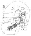
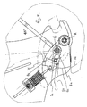
Figures 4 to 9 show the kinematics of the locking arrangement showing part of the coupling tower in a side view in different pivot positions; -
Fig. 10 shows a side view of the coupling procedure of the coupling tower and a part of the mount-on bracket; -
Fig. 11 shows the coupled situation fromFig. 10 ; -
Fig. 12 shows a perspective view the mount-on bracket; -
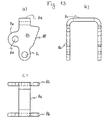
Figs. 13a, b, and c show an individual component of the coupling tower in a front, side, and overhead view; -
Fig. 14 shows the individual component of the coupling tower in a perspective view; -
Figs. 15 and 16 show part sections with a securing element and a securing contour shortly before the position in which the highest position is attained in relation to the mount-on bracket, and -
Figs. 17 and 18 show the part sections fromFigs. 15 and 16 in a final position. - The present embodiment example relates, according to
Fig. 1 , to atractor 20, which is intended to be coupled to a frontloader rocker arm 1. The frontloader rocker arm 1 is secured by means of a coupling device 4 to acoupling device 3 on the tractor. Thecoupling device 3 is secured firmly to the vehicle or to avehicle frame 2 of the vehicle. The coupling device on thefront loader 1, referred to hereinafter as the coupling tower 4, when coupled to the vehicle, is mechanically connected to the coupling device of the vehicle, referred to hereinafter as the mount-onbracket 3. -
Fig. 2 shows the two components in the coupled position. For simpler illustration, the remainder of the frontloader rocker arm 1 has been omitted. This would be connected to the left side, inFig. 2a , of the coupling tower 4, wherein the individual components are securely connected by bolts, which are guided through theholes 4a to 4c which can be identified there. - The coupling tower 4 has two carrier parts 5 (see
Fig. 2a ), which are designed as identical and are held at a predetermined distance from one another by aspacer plate 5d, such as can be seen for example inFig. 2c . For a more stable connection of the twocarrier parts 5, thespacer plate 5d is designed essentially in the form of an inverted Y. The twocarrier parts 5 can be welded to one another by means of thespacer plate 5d. Inside the twocarrier parts 5 are further components which are provided for locking the front loader to the vehicle. In particular, amounting bolt 5b is provided, which is mounted in two holes coaxial to one another, provided in thecarrier parts 5. The function of themounting bolts 5b will be described later. Further, in the lower region of thecarrier parts 5 holes are provided, aligned in each case coaxially to one another, which form a rotation axis A (seeFig. 2b, c ), the function of which is described below. - As can be seen from
Figs. 2b and 2c , two curved discs are provided, aligned parallel to one another, which serve as locking elements 6, described later, in the form of contoured plates. The two locking elements 6 are mounted so as to be rotatable about the axis A, as can be seen fromFig. 2b . The axis A is provided by a bolt, which is mounted in holes in thecarrier parts 5. - The locking element 6 has a passage aperture 6a, which can be seen, for example, in
Fig. 3 as well as inFigures 4 to 11 . The passage aperture is formed as a type of elongated slot. The locking element 6 in the present embodiment example is designed as a curved disc in the form of a segment of a circle. In this situation the circle-segment-related outer circumference section of the circle segment corresponds to the outer radius of a circle. According to a further embodiment, however, the outer circumference can also have a changing curvature, in order, for example, to strengthen the clamping effect with the mount-on bracket, as described later. - Further, a
hand lever 7 is provided in thecarrier part 5, which is mounted such as to rotate about an axle B (seeFig. 2b, c ). Thehand lever 7 is provided at its end opposite the handle with a sheet metal segment, on which a carrier bolt 7a is located, which extends perpendicular to this (seeFigs. 2c ,4-9 ). In addition to this, a curvedlongitudinal hole 5a is provided in thecarrier part 5, which lies within a radius about an axle B as the circle centre point (seeFig. 3 ). As a result, the carrier bolt 7a secured to thehand lever 7, which extends through the passage aperture 6a in the locking element 6 and through thelongitudinal hole 5a of thecarrier part 5, can be pivoted along thelongitudinal hole 5a on a circular path about the axle B together with thehand lever 7. The passage aperture 6a in this situation has an aperture width which is greater than the diameter of the carrier bolt 7a. - Further, a securing
element 8 is provided, such as can be seen, for example, inFig. 2c , and in particular as an individual component inFigs. 13 and14 . In this situation, this is a contoured sheet, which is mounted so as to rotate about an axle C provided in the locking element 6 (seeFigs. 3-9 ). - According to
Figs. 13 and14 , the securingelement 8 in the present embodiment example is shaped as a bar in the form of an inverted U. It consists of amiddle part 8a, connected to which are twolimbs 8b, angled essentially at right angles downwards inFigs. 13b and14 respectively. Provided at the free end of thelimbs 8b in each case is ahole 8c. Bothholes 8c are aligned coaxially to one another. The mid-point of the twoholes 8c lies on and defines an axis of rotation C (seeFig. 14 ), the function of which will be described later. Formed approximately in the middle of thelimbs 8b is a type oflug 8e, in which in each case afurther hole 8d is provided. Bothholes 8d are likewise aligned coaxially to one another. The mid-point of the twoholes 8d lies on and defines the axis of rotation E, the function of which is described later (seeFig. 14 ). Finally, acontour 8f is provided on the edge side opposite the lug 8e (seeFig. 13a ). The securingelement 8 is arranged in such a way, and contoured in such a way, that it is in contact tangentially with itscontour 8f on the carrier bolt 7a (seeFigs. 4-9 ). The interaction of thecontour 8f and the carrier bolt 7a is described later. - According to
Figs. 2b and 2c , atensioning spring assembly 9 is mounted on thecarrier part 5. Thetensioning spring assembly 9 is mounted at one end such as to be rotatable about an axle D in thecarrier part 5, and, in addition, is mounted at the other end such as to be rotatable about the axle E in the securingelement 8. - The mount-on
bracket 3 is explained hereinafter in greater detail by reference toFig. 12 . To secure the front loader, two mount-on brackets are provided, which in each case are located on one side of the vehicle. These are solid cast components, connected to thevehicle frame 2 by securingeyes 3 f, g, h and i. The mount-on bracket extends essentially perpendicular upwards and is designed in the upper third as curved in the direction of travel (seeFig. 1 ). Located at the upper end of the main body is a semicircular cut-out aperture 3a (seeFig. 12 ). Provided on the outer contour are a securingcontour 3d, a run-oncontour 3b, a lockingcontour 3e, as well as alower stop surface 3c, the functions of which are described in detail later. The securingcontour 3d has a contact surface 3dlrunning obliquely from below inFig. 12 . The oblique contact surface 3d1 merges into a straight part 3d2. Connected to the straight part, running at approximately a right angle is a shoulder part 3d3, which leads the securingcontour 3d back again into the main body of the mount-onbracket 3. - The coupling procedure is explained hereinafter: To couple up the
front loader 1, the coupling tower 4 is pivoted by means of the front loader's own hydraulics system, as can be seen inFig. 10 . On a vehicle with a height adjustable front axle, the front axle suspension is set to the lowest position, such that the front part of the vehicle and therefore the mount-onbracket 3 are lowered towards the front. In the lowered state, the vehicle is moved, in the coupling position, into the mount-on bracket. Theupper mounting bolt 5b of thecarrier part 5 in this situation is centred and suspended in the cut-out aperture 3a in the mount-onbracket 3. The coupling tower 4 is then pivoted back in the direction of arrow X by means of the front loader's own hydraulics system. This means that the lower section of the coupling tower is in this situation rotated in the direction of the mount-on bracket, such that thecoupling element 5c in the form of a cut-out aperture passes into engagement onto the projecting coupling element orlower stop 3c of the mount-onbracket 3. - The locking procedure is explained hereinafter: Due to the run-on
contour 3b in the mount-onbracket 3, during the coupling procedure the locking element 6 is pivoted upwards anti-clockwise about the axle A, against the spring force of the tensioning spring assembly 9 (seeFigs. 3 ,10 , in particular the arrow Y). In accordance with their interconnection, the other parts are also pivoted in sympathy. For this purpose reference is made in particular toFig. 3 . In the end position, i.e. in the locked state (seeFig. 11 ), the locking element 6 is again pressed downwards by the spring force of thetensioning spring assembly 9, and pivoted in the anti-clockwise direction against the direction of the arrow Y about the axle A. In this situation, a lockingsurface 6c comes in contact with a lockingcontour 3e of the mount-on bracket. Further, thelower contact surface 3c of the mount-onbracket 3 comes in contact with the correspondingcontour 5c of thecarrier part 5, as has already been indicated above. The locking procedure can be appreciated by means ofFigures 10 and11 . InFigure 10 , locking has not yet taken place. It can be seen that when thecarrier parts 5 are pivoted into the mount-onbracket 3, the run-on contour 6b of the locking element 6 slides along the run-oncontour 3b of the mount-on bracket, so that thetensioning spring assembly 9 is compressed. This sets the locking element 6 under preliminary tension. At the moment at which the locking element 6 has reached a position in which it has passed by the run-oncontour 3b, the locking element 6 can again pivot downwards, since the run-oncontour 3b has only a limited wall thickness, as can be seen in particular inFig. 12 . Due to the spring force of thespring assembly 9, the locking element 6 is pressed downwards, such that the lockingsurface 6c of the locking element 6 comes in contact with the lockingcontour 3e of the mount-onbracket 3, and the two parts lock with one another. Due to the spring force, the coupling position is set in the "locked" position, free of play, as represented inFig. 4 . - In order to prevent the possibility of an outside influence from beneath exerted on the locking element 6 causing unintentional release, the securing
element 8 is provided, which, when the coupling tower is raised at the securingcontour 3d, comes in contact with the mount-onbracket 3, and so prevents raising. This can best be seen inFig. 11 . In the "locked" position represented there, themiddle part 8a of the securingelement 8 is located opposite the securingcontour 3d of the mount-onbracket 3. If due to the outside influence of the locking element 6 there were to be a movement upwards, due for example to thefront loader 1 being raised upwards, themiddle part 8a of the securingelement 8 would come in contact with the securingcontour 3d of the mount-onbracket 3 and prevent any further movement. - The unlocking procedure is described hereinafter with reference to
Figs. 4-9 . Unlocking takes place by thehand lever 7 being pivoted out of the locking position into the unlocking position. The locking position is represented inFig. 4 . The unlocking position is represented inFig. 9 .Figures 5 to 8 show the individual lever positions in the different angle stages. If thelever 7 is pivoted, the drive force connections, as already described, cause the components of the locking arrangement likewise to pivot and move. - A point to be particularly emphasised in this situation is that the securing
element 8 is moved in such a way that it is not blocked by the securingcontour 3d of the mount-onbracket 3 but is firstly pivoted away out of this region and is then moved upwards. At the upper end of the securingcontour 3d, the securingelement 8 is then again pivoted by the spring force in such a way that the securingelement 8 remains in the "unlocked" position (seeFig. 9 ) even after the hand lever has been released and the front loader can again be coupled up. - The kinematic arrangements of the individual components are explained below.
- In
Fig. 4 , the "locked" position is represented. In this position the carrier bolt 7a in the passage aperture 6a is in its lowest position. Due to the spring force of thetensioning spring assembly 9, the securingelement 8 is pressed about the rotation axle C against the carrier bolt 7a. As already indicated, the rotation axle C is provided in the locking element 6. That is to say, upon a rotation of the locking element 6 in the clockwise direction, the rotation axle C likewise moves upwards on a circular trajectory about the rotation axle A of the locking element 6. In consequence, the securingelement 8, which is joint-connected at the rotation axle C to the locking element 6, also moves in a coupled movement. In the "locked" position shown inFig. 4 , the securingelement 8 is located with itsmiddle part 8a opposite the securingcontour 3d of the mount-onbracket 3. To better understand, for the mount-onbracket 3 only the securingcontour 3d is shown as a line. - In
Fig. 5 a position is represented in which thehand lever 7 has been pivoted by 10° in a clockwise direction. In this position, the carrier bolt 7a is no longer in its lowest position in the passage aperture 6a, but is now in its uppermost position. The locking element 6 in this situation has not yet moved. The securingelement 8 has, however, already rotated somewhat anti-clockwise about the axle C, against the spring force of thetensioning spring assembly 9. The reason for this is that, due to the spring pre-tension, the securing element with itscontour 8f is constantly in contact with the carrier bolt 7a. Due to the movement of the carrier bolt 7a and contact with thecontour 8f, the securingelement 8 can as a consequence be easily pivoted. Although themiddle part 8a of the securingelement 8 is still located opposite the securingcontour 3d of the mount-onbracket 3, in the figure it is already pivoted somewhat further to the left. - In
Fig. 6 a position is represented in which theactuating lever 7 has been pivoted by 25° in a clockwise direction. In this position, the carrier bolt 7a moves further upwards, in a circular trajectory about the axle B. In this position the locking element 6 is already somewhat raised. The securingelement 8 continues to be in the position pivoted to the left in the anticlockwise direction. However, with the movement of the locking element 6, the rotation axle C is simultaneously raised and pivoted, such that the securingelement 8 joint-connected to the rotation axle C is also raised. It can now be seen that the securing element is already pivoted so far that it is moved past the securingcontour 3d. - In
Fig. 7 a position is represented in which theactuation lever 7 has been pivoted by 35° in the clockwise direction. In this position, the locking element 6 is further raised. The securingelement 8 is still in the position pivoted to the left, anti-clockwise, and has likewise been raised still further. - In
Fig. 8 a position is represented in which theactuation lever 7 has been pivoted by 45° in the clockwise direction. In this position the locking element 6 is raised sufficiently far that the lockingsurface 6c is no longer in contact with the lockingcontour 3e. This means that an unlocked state already exists. Themiddle part 8a of the securingelement 8 is located in its highest position, i.e. the bar part formed by themiddle part 8a is in the position shortly before it snaps over the securingcontour 3d. - Represented in
Fig. 9 is the final "unlocked" state. The locking element 6 is in this case pivoted entirely upwards. The carrier bolt 7a is located in the uppermost position. By way of thecontour 8f of the securingelement 8, the carrier bolt 7a now lies in a cut-out aperture and fixes the securingelement 8 in this position. In this position the bar of themiddle part 8a snaps over the securingcontour 3d and holds the position against the spring force of thespring assembly 9 which in this position is compressed to a maximum. - The positions of the securing
element 8 are shown more precisely inFigs. 15 to 18 . InFigs. 15 and 16 a situation is represented in which the securingelement 8 is shortly before the position in which it attains the highest position in relation to the mount-onbracket 3. Themiddle part 8a of the securingelement 8, forming the bar, is still in contact with the oblique surface of the securingcontour 3d.Figs. 17 and 18 then show the end position in which themiddle part 8a of the bar of the securingelement 8 has moved out over the highest position of the securingcontour 8d. Due to the spring force of thetensioning spring assembly 9, the bar is "hooked" into the securingcontour 3d, such that the securing element remains in this position. - The uncoupling procedure is carried out in the reverse sequence. As soon as the coupling tower 4 with its locking element 6 is pivoted out of the region of the securing
contour 3d and is no longer in contact, the locking device by means of the spring force of thetensioning spring assembly 9 is brought into the "locked" position (seeFig. 4 ). From this position thefront loader 1 can be coupled on again.
Thehand lever 7 is provided with a display device 7b in the form of a pointer, in order to indicate to the operator the function of the position which has been set. To do this, a scale, not represented, is fixed to thecarrier part 5, which defines the two positions "locked" and "unlocked" by the pointer position.
Claims (13)
- A coupling device for the detachable coupling of a working device (1), in particular of a front loader, to a utility vehicle, in particular an agricultural tractor (20), wherein the coupling device has:- a working device coupling bracket (4), which can be or has been connected to a working device (1), and- a utility vehicle coupling bracket (3), which can be or has been connected to a utility vehicle (20),- working device coupling element means (5b, 5c), provided on the working device coupling bracket (4), and- utility vehicle coupling element means (3a, 3c), provided on the utility vehicle coupling bracket (3),- wherein the coupling element means can be coupled together, by means of a relative coupling movement between the working device coupling bracket and utility vehicle coupling bracket, and- at least one locking element (6) located in a movable manner on the working device coupling bracket (4), which is pre-tensioned into a locked position in which a relative movement between the working device coupling bracket 94) and the utility vehicle coupling bracket (3) in a direction opposite to the relative coupling movement is prevented, the locking element being moveable into an unlocked position by the actuating of an actuation element (carrier part and hand lever 5, 7),- the coupling device being characterised by the inclusion of a securing element (8) which is pre-tensioned into a securing position, and is coupled to the locking element (6) in such a way that, when an external force is applied, to the locking element to move it towards the unlocked position, it contacts the utility vehicle coupling bracket (3d) to prevent further movement of the locking element towards the unlocked position is prevented, and- wherein the actuation element (7) is coupled in such a way to the locking element (6) and the securing element (8) that, when the actuation element (7) is moved out of the securing position, the locking element (6) is moved together with the securing element (8) into the unlocked position.
- A coupling device according to Claim 1, characterised in that- first coupling element means (5b,3a) on the working device coupling bracket (4) and the utility vehicle coupling bracket (3) can be coupled by a first essentially linear relative coupling movement between the coupling brackets, and in that- second coupling element means (5c,3c) on the coupling brackets (4,3) can be coupled by a second relative pivoting coupling movement between coupling brackets (4,3) about a pivot axis which lies in the region of the first coupled coupling element means (5b,3a), and- wherein the locking element (6) in the locked position prevents a relative movement between the coupling brackets (4,3) in a direction opposite to the second relative coupling movement.
- A coupling device according to Claim 1 or 2, characterised in that the utility vehicle coupling element means comprises- a first upwardly open cut-out (3a), and second cut-out apertures (3c) on both sides of the utility vehicle coupling bracket (3), which are opened towards the working device coupling element means,- in that the working device coupling element means comprises a mounting bolt (5b) adapted to be received in the first upwardly open cut-out aperture (3a) and formations (5c) on the working device coupling element bracket (4) designed for engagement with the second cut-out apertures (3c).
- A coupling device according to any one of the preceding claims, characterised in that the locking element (6) is on the working device coupling bracket (4), for pivoting about a first axis (A).
- A coupling device according to Claim 4, characterised in that the securing element (8) is connected to the locking element (6) in a manner such as to be capable of pivoting about a securing element axis (C), which is parallel and displaced from to the first axis (A).
- A coupling device according to Claim 5, characterised in that the locking element (6) has a run-on contour (6b) and the utility vehicle coupling bracket (3) has a corresponding run-on contour (3b), wherein the locking element (6) during the second relative coupling movement is moved by mutual contact of the two run-on contours (3b, 6b) into the unlocked position, and in that the locking element (6), after completion of the second relative coupling movement, is moved by pre-tension into the locked position, in which a locking surface (6c) of the locking element (6) and a locking contour (3e) of the utility vehicle coupling bracket (3) are in contact with one another.
- A coupling device according to any one of Claims 4 to 6, characterised in that the actuation element (7) is mounted on the working device coupling bracket (3) so as to be pivotable about an actuation element axis (B) and has a bolt (7a) which can be moved together with the actuation element in a trajectory about the actuation element axis (B) and which extends through a passage aperture (6a) provided in the locking element (6), wherein the passage aperture (6a) is offset relative to the first axis (A) and at least in the direction of the movement of the bolt (7a), is larger than a diameter of the bolt (7a).
- A coupling device according to Claim 7, characterised in that the securing element (8) is pre-tensioned into the securing position and the locking element (6) is pre-tensioned into the locked position by a tensioning element (9), which acts between the working device coupling element (4) and the securing element (8) at a point offset relative to the securing element axis (C).
- A coupling device according to Claim 8, characterised in that the securing element (8) is pre-tensioned by the tensioning element in contact with the bolt (7a) of the actuation element (7).
- A coupling device according to any one of Claims 7 to 9, characterised in that the actuation element (7) has an actuation lever for the pivoting of the actuation element and a plate, by means of which the bolt (7a) is connected to the actuation lever.
- A coupling device according to any one of the preceding claims, characterised in that, in an unlocking end position of the actuation element (7) in which the locking element (6) is unlocked, the securing element (8), due to the pre-tensioning, is held in engagement with a section of the utility vehicle coupling bracket (3).
- A utility vehicle, in particular an agricultural tractor, with a working device connected therewith by a coupling device according to any one of the preceding claims.
- Agricultural tractor with a front loader connected therewith by two coupling devices, according to any one of Claims 1 to 11, which are arranged on both sides of the agricultural tractor in the region between a front axle and a driver's cab of the agricultural tractor, and which in each case couple an arm of the front loader to the agricultural tractor.
Applications Claiming Priority (1)
| Application Number | Priority Date | Filing Date | Title |
|---|---|---|---|
| DE200710048334 DE102007048334A1 (en) | 2007-10-09 | 2007-10-09 | Coupling device with semi-automatic locking |
Publications (3)
| Publication Number | Publication Date |
|---|---|
| EP2048290A2 true EP2048290A2 (en) | 2009-04-15 |
| EP2048290A3 EP2048290A3 (en) | 2013-02-27 |
| EP2048290B1 EP2048290B1 (en) | 2014-03-05 |
Family
ID=40091429
Family Applications (1)
| Application Number | Title | Priority Date | Filing Date |
|---|---|---|---|
| EP20080017346 Active EP2048290B1 (en) | 2007-10-09 | 2008-10-02 | Coupling device with semi-automatic locking for the detachable coupling of an implement to a utility vehicle |
Country Status (2)
| Country | Link |
|---|---|
| EP (1) | EP2048290B1 (en) |
| DE (1) | DE102007048334A1 (en) |
Citations (4)
| Publication number | Priority date | Publication date | Assignee | Title |
|---|---|---|---|---|
| DE3229947A1 (en) | 1982-08-12 | 1984-02-16 | Wilhelm Stoll Maschinenfabrik Gmbh, 3325 Lengede | Set-aside front loader which can be releasably attached to a tractor |
| DE3630976A1 (en) | 1985-09-12 | 1987-03-19 | Hydrac Puehringer Ges M B H & | Front loader |
| EP1528164A1 (en) | 2003-10-31 | 2005-05-04 | Franz Hauer | Apparatus for detachably coupling an implement, especially a loading arm, to a vehicle |
| DE202006007042U1 (en) | 2006-04-28 | 2006-10-12 | Deere & Company, Moline | Front loader/mounting console combination for a tractor comprises clamping units each connected to a locking hook so that a clamping unit is formed relative to the pivoting axle of the hook |
Family Cites Families (7)
| Publication number | Priority date | Publication date | Assignee | Title |
|---|---|---|---|---|
| AT307990B (en) * | 1970-07-27 | 1973-06-12 | Puehringer Josef | Device for coupling a parkable front loader with an agricultural tractor or the like. |
| JPS5820343B2 (en) * | 1978-03-30 | 1983-04-22 | キヤタピラ−三菱株式会社 | Quitsuku Kabra |
| DE3437931A1 (en) * | 1984-10-17 | 1986-04-24 | Macmoter S.P.A., Modigliana | ATTACHMENT HOLDER |
| FR2747137B1 (en) * | 1996-04-09 | 1998-06-19 | Manip | DEVICE FOR CONNECTING A FRONTAL TOOL WITH A MACHINE, IN PARTICULAR A TRACTOR |
| FR2830166B1 (en) * | 2001-09-28 | 2003-11-28 | Cochet Sa | AUTOMATIC HITCHING AND LOCKING DEVICE OF AN AGRICULTURAL MACHINE AT THE BACK OF A TRACTOR |
| US6994511B2 (en) * | 2003-11-21 | 2006-02-07 | Westendorf Manufacturing Co., Inc. | Loader assembly, combination motor vehicle and loader assembly, hydraulic cylinders and methods for operating a loader assembly |
| FR2871485B1 (en) * | 2004-06-10 | 2006-09-01 | Etude Et D Innovation Dans Le | DEVICE FOR COUPLING A LOADER ON A TRACTOR |
-
2007
- 2007-10-09 DE DE200710048334 patent/DE102007048334A1/en not_active Ceased
-
2008
- 2008-10-02 EP EP20080017346 patent/EP2048290B1/en active Active
Patent Citations (4)
| Publication number | Priority date | Publication date | Assignee | Title |
|---|---|---|---|---|
| DE3229947A1 (en) | 1982-08-12 | 1984-02-16 | Wilhelm Stoll Maschinenfabrik Gmbh, 3325 Lengede | Set-aside front loader which can be releasably attached to a tractor |
| DE3630976A1 (en) | 1985-09-12 | 1987-03-19 | Hydrac Puehringer Ges M B H & | Front loader |
| EP1528164A1 (en) | 2003-10-31 | 2005-05-04 | Franz Hauer | Apparatus for detachably coupling an implement, especially a loading arm, to a vehicle |
| DE202006007042U1 (en) | 2006-04-28 | 2006-10-12 | Deere & Company, Moline | Front loader/mounting console combination for a tractor comprises clamping units each connected to a locking hook so that a clamping unit is formed relative to the pivoting axle of the hook |
Also Published As
| Publication number | Publication date |
|---|---|
| EP2048290A3 (en) | 2013-02-27 |
| EP2048290B1 (en) | 2014-03-05 |
| DE102007048334A1 (en) | 2009-04-23 |
Similar Documents
| Publication | Publication Date | Title |
|---|---|---|
| DE3017890C2 (en) | Safety device for a door lock arranged in a vehicle door | |
| EP3659833B1 (en) | Trailer coupling and load support device for a trailer coupling | |
| DE602004001823T2 (en) | Locking device for vehicle seats | |
| EP2076631B1 (en) | Coupler for excavators | |
| US9580938B2 (en) | Motor vehicle door lock | |
| EP2133495B1 (en) | Motor vehicle lock | |
| EP2964858B1 (en) | Lock for a motor vehicle | |
| DE19962653A1 (en) | Fixture for vehicle seat comprises release lever and fastening plate with mechanism controlling rotation of lever through engagement | |
| KR101534465B1 (en) | Locking device for a fold-over backrest of a seat | |
| WO2013004450A1 (en) | Fitting system for a vehicle seat | |
| DE102010039553A1 (en) | The vehicle seat reclining device | |
| US7726731B2 (en) | Device for removably fitting to prams carrycot seats and carrycots being provided with an articulated handle | |
| EP1976723A1 (en) | Fitting for a vehicle seat | |
| EP3924217B1 (en) | Locking device and vehicle seat | |
| EP2048290B1 (en) | Coupling device with semi-automatic locking for the detachable coupling of an implement to a utility vehicle | |
| CA2856624C (en) | Front loader arrangement | |
| EP2199502B1 (en) | Motor vehicle lock | |
| EP1745949B1 (en) | Trailer coupling with safety locking mechanism | |
| AU2008243058B2 (en) | Implement Coupling System | |
| CN105917061A (en) | Motor vehicle door-handle | |
| EP0921029B1 (en) | Vehicle seat with tiltable backrest | |
| DE2754815C2 (en) | Backrest locking for vehicle seats | |
| WO2008000240A2 (en) | Vehicle seat | |
| FI3929361T3 (en) | Tool holding device and mobile working machine | |
| DE102005007122B4 (en) | Motor vehicle seat with folding backrest |
Legal Events
| Date | Code | Title | Description |
|---|---|---|---|
| PUAI | Public reference made under article 153(3) epc to a published international application that has entered the european phase |
Free format text: ORIGINAL CODE: 0009012 |
|
| AK | Designated contracting states |
Kind code of ref document: A2 Designated state(s): AT BE BG CH CY CZ DE DK EE ES FI FR GB GR HR HU IE IS IT LI LT LU LV MC MT NL NO PL PT RO SE SI SK TR |
|
| AX | Request for extension of the european patent |
Extension state: AL BA MK RS |
|
| PUAL | Search report despatched |
Free format text: ORIGINAL CODE: 0009013 |
|
| AK | Designated contracting states |
Kind code of ref document: A3 Designated state(s): AT BE BG CH CY CZ DE DK EE ES FI FR GB GR HR HU IE IS IT LI LT LU LV MC MT NL NO PL PT RO SE SI SK TR |
|
| AX | Request for extension of the european patent |
Extension state: AL BA MK RS |
|
| RIC1 | Information provided on ipc code assigned before grant |
Ipc: B62D 49/02 20060101ALI20130124BHEP Ipc: E02F 3/627 20060101AFI20130124BHEP Ipc: A01B 59/00 20060101ALI20130124BHEP Ipc: A01D 87/00 20060101ALI20130124BHEP |
|
| 17P | Request for examination filed |
Effective date: 20130827 |
|
| RBV | Designated contracting states (corrected) |
Designated state(s): AT BE BG CH CY CZ DE DK EE ES FI FR GB GR HR HU IE IS IT LI LT LU LV MC MT NL NO PL PT RO SE SI SK TR |
|
| GRAP | Despatch of communication of intention to grant a patent |
Free format text: ORIGINAL CODE: EPIDOSNIGR1 |
|
| AKX | Designation fees paid |
Designated state(s): AT BE BG CH CY CZ DE DK EE ES FI FR GB GR HR HU IE IS IT LI LT LU LV MC MT NL NO PL PT RO SE SI SK TR |
|
| RIC1 | Information provided on ipc code assigned before grant |
Ipc: A01B 59/00 20060101ALI20130930BHEP Ipc: E02F 3/627 20060101AFI20130930BHEP Ipc: A01D 87/00 20060101ALI20130930BHEP Ipc: B62D 49/02 20060101ALI20130930BHEP |
|
| INTG | Intention to grant announced |
Effective date: 20131016 |
|
| GRAS | Grant fee paid |
Free format text: ORIGINAL CODE: EPIDOSNIGR3 |
|
| GRAA | (expected) grant |
Free format text: ORIGINAL CODE: 0009210 |
|
| AK | Designated contracting states |
Kind code of ref document: B1 Designated state(s): AT BE BG CH CY CZ DE DK EE ES FI FR GB GR HR HU IE IS IT LI LT LU LV MC MT NL NO PL PT RO SE SI SK TR |
|
| REG | Reference to a national code |
Ref country code: GB Ref legal event code: FG4D |
|
| REG | Reference to a national code |
Ref country code: CH Ref legal event code: EP |
|
| REG | Reference to a national code |
Ref country code: AT Ref legal event code: REF Ref document number: 654988 Country of ref document: AT Kind code of ref document: T Effective date: 20140315 |
|
| REG | Reference to a national code |
Ref country code: IE Ref legal event code: FG4D |
|
| REG | Reference to a national code |
Ref country code: DE Ref legal event code: R096 Ref document number: 602008030553 Country of ref document: DE Effective date: 20140417 |
|
| REG | Reference to a national code |
Ref country code: SE Ref legal event code: TRGR |
|
| REG | Reference to a national code |
Ref country code: NL Ref legal event code: VDEP Effective date: 20140305 |
|
| PG25 | Lapsed in a contracting state [announced via postgrant information from national office to epo] |
Ref country code: NO Free format text: LAPSE BECAUSE OF FAILURE TO SUBMIT A TRANSLATION OF THE DESCRIPTION OR TO PAY THE FEE WITHIN THE PRESCRIBED TIME-LIMIT Effective date: 20140605 Ref country code: LT Free format text: LAPSE BECAUSE OF FAILURE TO SUBMIT A TRANSLATION OF THE DESCRIPTION OR TO PAY THE FEE WITHIN THE PRESCRIBED TIME-LIMIT Effective date: 20140305 |
|
| REG | Reference to a national code |
Ref country code: LT Ref legal event code: MG4D |
|
| PG25 | Lapsed in a contracting state [announced via postgrant information from national office to epo] |
Ref country code: CY Free format text: LAPSE BECAUSE OF FAILURE TO SUBMIT A TRANSLATION OF THE DESCRIPTION OR TO PAY THE FEE WITHIN THE PRESCRIBED TIME-LIMIT Effective date: 20140305 Ref country code: FI Free format text: LAPSE BECAUSE OF FAILURE TO SUBMIT A TRANSLATION OF THE DESCRIPTION OR TO PAY THE FEE WITHIN THE PRESCRIBED TIME-LIMIT Effective date: 20140305 |
|
| PG25 | Lapsed in a contracting state [announced via postgrant information from national office to epo] |
Ref country code: LV Free format text: LAPSE BECAUSE OF FAILURE TO SUBMIT A TRANSLATION OF THE DESCRIPTION OR TO PAY THE FEE WITHIN THE PRESCRIBED TIME-LIMIT Effective date: 20140305 Ref country code: HR Free format text: LAPSE BECAUSE OF FAILURE TO SUBMIT A TRANSLATION OF THE DESCRIPTION OR TO PAY THE FEE WITHIN THE PRESCRIBED TIME-LIMIT Effective date: 20140305 |
|
| PG25 | Lapsed in a contracting state [announced via postgrant information from national office to epo] |
Ref country code: RO Free format text: LAPSE BECAUSE OF FAILURE TO SUBMIT A TRANSLATION OF THE DESCRIPTION OR TO PAY THE FEE WITHIN THE PRESCRIBED TIME-LIMIT Effective date: 20140305 Ref country code: NL Free format text: LAPSE BECAUSE OF FAILURE TO SUBMIT A TRANSLATION OF THE DESCRIPTION OR TO PAY THE FEE WITHIN THE PRESCRIBED TIME-LIMIT Effective date: 20140305 Ref country code: IS Free format text: LAPSE BECAUSE OF FAILURE TO SUBMIT A TRANSLATION OF THE DESCRIPTION OR TO PAY THE FEE WITHIN THE PRESCRIBED TIME-LIMIT Effective date: 20140705 Ref country code: EE Free format text: LAPSE BECAUSE OF FAILURE TO SUBMIT A TRANSLATION OF THE DESCRIPTION OR TO PAY THE FEE WITHIN THE PRESCRIBED TIME-LIMIT Effective date: 20140305 Ref country code: BE Free format text: LAPSE BECAUSE OF FAILURE TO SUBMIT A TRANSLATION OF THE DESCRIPTION OR TO PAY THE FEE WITHIN THE PRESCRIBED TIME-LIMIT Effective date: 20140305 Ref country code: BG Free format text: LAPSE BECAUSE OF FAILURE TO SUBMIT A TRANSLATION OF THE DESCRIPTION OR TO PAY THE FEE WITHIN THE PRESCRIBED TIME-LIMIT Effective date: 20140605 |
|
| PG25 | Lapsed in a contracting state [announced via postgrant information from national office to epo] |
Ref country code: SK Free format text: LAPSE BECAUSE OF FAILURE TO SUBMIT A TRANSLATION OF THE DESCRIPTION OR TO PAY THE FEE WITHIN THE PRESCRIBED TIME-LIMIT Effective date: 20140305 Ref country code: ES Free format text: LAPSE BECAUSE OF FAILURE TO SUBMIT A TRANSLATION OF THE DESCRIPTION OR TO PAY THE FEE WITHIN THE PRESCRIBED TIME-LIMIT Effective date: 20140305 Ref country code: PL Free format text: LAPSE BECAUSE OF FAILURE TO SUBMIT A TRANSLATION OF THE DESCRIPTION OR TO PAY THE FEE WITHIN THE PRESCRIBED TIME-LIMIT Effective date: 20140305 |
|
| REG | Reference to a national code |
Ref country code: DE Ref legal event code: R097 Ref document number: 602008030553 Country of ref document: DE |
|
| PG25 | Lapsed in a contracting state [announced via postgrant information from national office to epo] |
Ref country code: PT Free format text: LAPSE BECAUSE OF FAILURE TO SUBMIT A TRANSLATION OF THE DESCRIPTION OR TO PAY THE FEE WITHIN THE PRESCRIBED TIME-LIMIT Effective date: 20140707 |
|
| PLBE | No opposition filed within time limit |
Free format text: ORIGINAL CODE: 0009261 |
|
| STAA | Information on the status of an ep patent application or granted ep patent |
Free format text: STATUS: NO OPPOSITION FILED WITHIN TIME LIMIT |
|
| PG25 | Lapsed in a contracting state [announced via postgrant information from national office to epo] |
Ref country code: DK Free format text: LAPSE BECAUSE OF FAILURE TO SUBMIT A TRANSLATION OF THE DESCRIPTION OR TO PAY THE FEE WITHIN THE PRESCRIBED TIME-LIMIT Effective date: 20140305 |
|
| 26N | No opposition filed |
Effective date: 20141208 |
|
| REG | Reference to a national code |
Ref country code: DE Ref legal event code: R097 Ref document number: 602008030553 Country of ref document: DE Effective date: 20141208 |
|
| PG25 | Lapsed in a contracting state [announced via postgrant information from national office to epo] |
Ref country code: MC Free format text: LAPSE BECAUSE OF FAILURE TO SUBMIT A TRANSLATION OF THE DESCRIPTION OR TO PAY THE FEE WITHIN THE PRESCRIBED TIME-LIMIT Effective date: 20140305 Ref country code: LU Free format text: LAPSE BECAUSE OF FAILURE TO SUBMIT A TRANSLATION OF THE DESCRIPTION OR TO PAY THE FEE WITHIN THE PRESCRIBED TIME-LIMIT Effective date: 20141002 Ref country code: SI Free format text: LAPSE BECAUSE OF FAILURE TO SUBMIT A TRANSLATION OF THE DESCRIPTION OR TO PAY THE FEE WITHIN THE PRESCRIBED TIME-LIMIT Effective date: 20140305 |
|
| REG | Reference to a national code |
Ref country code: CH Ref legal event code: PL |
|
| REG | Reference to a national code |
Ref country code: IE Ref legal event code: MM4A |
|
| PG25 | Lapsed in a contracting state [announced via postgrant information from national office to epo] |
Ref country code: LI Free format text: LAPSE BECAUSE OF NON-PAYMENT OF DUE FEES Effective date: 20141031 Ref country code: CH Free format text: LAPSE BECAUSE OF NON-PAYMENT OF DUE FEES Effective date: 20141031 |
|
| REG | Reference to a national code |
Ref country code: FR Ref legal event code: PLFP Year of fee payment: 8 |
|
| PG25 | Lapsed in a contracting state [announced via postgrant information from national office to epo] |
Ref country code: IE Free format text: LAPSE BECAUSE OF NON-PAYMENT OF DUE FEES Effective date: 20141002 |
|
| PG25 | Lapsed in a contracting state [announced via postgrant information from national office to epo] |
Ref country code: GR Free format text: LAPSE BECAUSE OF FAILURE TO SUBMIT A TRANSLATION OF THE DESCRIPTION OR TO PAY THE FEE WITHIN THE PRESCRIBED TIME-LIMIT Effective date: 20140606 |
|
| PG25 | Lapsed in a contracting state [announced via postgrant information from national office to epo] |
Ref country code: TR Free format text: LAPSE BECAUSE OF FAILURE TO SUBMIT A TRANSLATION OF THE DESCRIPTION OR TO PAY THE FEE WITHIN THE PRESCRIBED TIME-LIMIT Effective date: 20140305 Ref country code: HU Free format text: LAPSE BECAUSE OF FAILURE TO SUBMIT A TRANSLATION OF THE DESCRIPTION OR TO PAY THE FEE WITHIN THE PRESCRIBED TIME-LIMIT; INVALID AB INITIO Effective date: 20081002 Ref country code: MT Free format text: LAPSE BECAUSE OF FAILURE TO SUBMIT A TRANSLATION OF THE DESCRIPTION OR TO PAY THE FEE WITHIN THE PRESCRIBED TIME-LIMIT Effective date: 20140305 |
|
| REG | Reference to a national code |
Ref country code: FR Ref legal event code: PLFP Year of fee payment: 9 |
|
| REG | Reference to a national code |
Ref country code: FR Ref legal event code: PLFP Year of fee payment: 10 |
|
| PGFP | Annual fee paid to national office [announced via postgrant information from national office to epo] |
Ref country code: IT Payment date: 20171025 Year of fee payment: 10 Ref country code: GB Payment date: 20171019 Year of fee payment: 10 |
|
| REG | Reference to a national code |
Ref country code: FR Ref legal event code: PLFP Year of fee payment: 11 |
|
| PGFP | Annual fee paid to national office [announced via postgrant information from national office to epo] |
Ref country code: AT Payment date: 20181022 Year of fee payment: 11 |
|
| GBPC | Gb: european patent ceased through non-payment of renewal fee |
Effective date: 20181002 |
|
| PG25 | Lapsed in a contracting state [announced via postgrant information from national office to epo] |
Ref country code: IT Free format text: LAPSE BECAUSE OF NON-PAYMENT OF DUE FEES Effective date: 20181002 Ref country code: GB Free format text: LAPSE BECAUSE OF NON-PAYMENT OF DUE FEES Effective date: 20181002 |
|
| REG | Reference to a national code |
Ref country code: AT Ref legal event code: MM01 Ref document number: 654988 Country of ref document: AT Kind code of ref document: T Effective date: 20191002 |
|
| PG25 | Lapsed in a contracting state [announced via postgrant information from national office to epo] |
Ref country code: AT Free format text: LAPSE BECAUSE OF NON-PAYMENT OF DUE FEES Effective date: 20191002 |
|
| REG | Reference to a national code |
Ref country code: DE Ref legal event code: R084 Ref document number: 602008030553 Country of ref document: DE |
|
| P01 | Opt-out of the competence of the unified patent court (upc) registered |
Effective date: 20230518 |
|
| PGFP | Annual fee paid to national office [announced via postgrant information from national office to epo] |
Ref country code: CZ Payment date: 20230922 Year of fee payment: 16 |
|
| PGFP | Annual fee paid to national office [announced via postgrant information from national office to epo] |
Ref country code: SE Payment date: 20231019 Year of fee payment: 16 |
|
| PG25 | Lapsed in a contracting state [announced via postgrant information from national office to epo] |
Ref country code: CZ Free format text: LAPSE BECAUSE OF NON-PAYMENT OF DUE FEES Effective date: 20241002 |
|
| REG | Reference to a national code |
Ref country code: SE Ref legal event code: EUG |
|
| PG25 | Lapsed in a contracting state [announced via postgrant information from national office to epo] |
Ref country code: SE Free format text: LAPSE BECAUSE OF NON-PAYMENT OF DUE FEES Effective date: 20241003 |
|
| PGFP | Annual fee paid to national office [announced via postgrant information from national office to epo] |
Ref country code: DE Payment date: 20251021 Year of fee payment: 18 |
|
| PGFP | Annual fee paid to national office [announced via postgrant information from national office to epo] |
Ref country code: FR Payment date: 20251029 Year of fee payment: 18 |