EP2048074A2 - Dämpfereinstellung für Motorrad - Google Patents
Dämpfereinstellung für Motorrad Download PDFInfo
- Publication number
- EP2048074A2 EP2048074A2 EP08017817A EP08017817A EP2048074A2 EP 2048074 A2 EP2048074 A2 EP 2048074A2 EP 08017817 A EP08017817 A EP 08017817A EP 08017817 A EP08017817 A EP 08017817A EP 2048074 A2 EP2048074 A2 EP 2048074A2
- Authority
- EP
- European Patent Office
- Prior art keywords
- straddle
- adjuster
- footrest
- type vehicle
- vehicle
- Prior art date
- Legal status (The legal status is an assumption and is not a legal conclusion. Google has not performed a legal analysis and makes no representation as to the accuracy of the status listed.)
- Granted
Links
Images



Classifications
-
- B—PERFORMING OPERATIONS; TRANSPORTING
- B62—LAND VEHICLES FOR TRAVELLING OTHERWISE THAN ON RAILS
- B62K—CYCLES; CYCLE FRAMES; CYCLE STEERING DEVICES; RIDER-OPERATED TERMINAL CONTROLS SPECIALLY ADAPTED FOR CYCLES; CYCLE AXLE SUSPENSIONS; CYCLE SIDECARS, FORECARS, OR THE LIKE
- B62K11/00—Motorcycles, engine-assisted cycles or motor scooters with one or two wheels
- B62K11/02—Frames
- B62K11/04—Frames characterised by the engine being between front and rear wheels
-
- B—PERFORMING OPERATIONS; TRANSPORTING
- B62—LAND VEHICLES FOR TRAVELLING OTHERWISE THAN ON RAILS
- B62K—CYCLES; CYCLE FRAMES; CYCLE STEERING DEVICES; RIDER-OPERATED TERMINAL CONTROLS SPECIALLY ADAPTED FOR CYCLES; CYCLE AXLE SUSPENSIONS; CYCLE SIDECARS, FORECARS, OR THE LIKE
- B62K25/00—Axle suspensions
- B62K25/04—Axle suspensions for mounting axles resiliently on cycle frame or fork
- B62K25/28—Axle suspensions for mounting axles resiliently on cycle frame or fork with pivoted chain-stay
- B62K25/283—Axle suspensions for mounting axles resiliently on cycle frame or fork with pivoted chain-stay for cycles without a pedal crank, e.g. motorcycles
-
- B—PERFORMING OPERATIONS; TRANSPORTING
- B62—LAND VEHICLES FOR TRAVELLING OTHERWISE THAN ON RAILS
- B62K—CYCLES; CYCLE FRAMES; CYCLE STEERING DEVICES; RIDER-OPERATED TERMINAL CONTROLS SPECIALLY ADAPTED FOR CYCLES; CYCLE AXLE SUSPENSIONS; CYCLE SIDECARS, FORECARS, OR THE LIKE
- B62K25/00—Axle suspensions
- B62K25/04—Axle suspensions for mounting axles resiliently on cycle frame or fork
- B62K25/28—Axle suspensions for mounting axles resiliently on cycle frame or fork with pivoted chain-stay
- B62K25/286—Axle suspensions for mounting axles resiliently on cycle frame or fork with pivoted chain-stay the shock absorber being connected to the chain-stay via a linkage mechanism
-
- B—PERFORMING OPERATIONS; TRANSPORTING
- B62—LAND VEHICLES FOR TRAVELLING OTHERWISE THAN ON RAILS
- B62K—CYCLES; CYCLE FRAMES; CYCLE STEERING DEVICES; RIDER-OPERATED TERMINAL CONTROLS SPECIALLY ADAPTED FOR CYCLES; CYCLE AXLE SUSPENSIONS; CYCLE SIDECARS, FORECARS, OR THE LIKE
- B62K25/00—Axle suspensions
- B62K25/04—Axle suspensions for mounting axles resiliently on cycle frame or fork
- B62K2025/048—Axle suspensions for mounting axles resiliently on cycle frame or fork with suspension manual adjustment details
Definitions
- the present invention relates to a straddle-type vehicle such as a motorcycle in which a rear suspension that buffers an external load that acts on a rear wheel is disposed between a rear arm and a vehicle body frame.
- a straddle-type vehicle comprising: a vehicle body frame, at least one footrest on which a rider sitting on a rear seat of the straddle-type vehicle can place his/her foot, and which is attached to the vehicle body frame, a rear arm swingably supported by the vehicle body frame and having a rear suspension, the rear suspension including at least one adjuster configured to remotely adjust at least one operation characteristic of the rear suspension, wherein the adjuster is at least partly disposed below the footrest when viewed from a rear of the straddle-type vehicle.
- the adjuster can be positioned in a location that can be seen from the side of the vehicle, and this in itself improves operability.
- a vehicle body cover covers at least a side of a rear portion of the vehicle body frame, wherein, preferably, the footrest protrudes outwards from the vehicle body cover, and wherein, preferably, the adjuster is at least partly disposed in vehicle width direction on an inside of an outer end surface of the vehicle body cover when viewed from the rear of the straddle-type vehicle.
- the adjuster when the adjuster is viewed from the vehicle rear, it is positioned inside the vehicle body cover outside end surface in the vehicle width direction as well as below the footrest.
- the rear seat rider mistaking the adjuster for the footrest and placing their foot on it can be reliably inhibited.
- the adjuster comprises an adjusting knob which is disposed in vehicle width direction on the inside of the outer end surface of the vehicle body cover and/or below the footrest when viewed from the rear of the vehicle.
- the footrest includes a footrest bracket attached to the vehicle body frame and a footrest main body attached to the footrest bracket, and, preferably, the adjuster, in particular the adjusting knob, is attached to the footrest bracket.
- the vehicle body frame includes a rear frame and a fuel tank disposed on an inside of the vehicle body frame, and, preferably, the footrest bracket is attached to a bottom part of the rear frame.
- the footrest bracket is attached by a bolt that is inserted from bottom to top in the bottom part of the rear frame.
- an exhaust system including a muffler is disposed so as to pass through at least one side of the straddle-type vehicle, and, preferably, the adjuster, in particular the adjusting knob, is located in a space surrounded by at least two of the vehicle body cover, the footrest and the muffler when viewed from the rear of the straddle-type vehicle.
- the vehicle body cover includes a mudguard that covers a rear wheel of the straddle-type vehicle from a top thereof and a fender main body that extends upward from a side edge portion of the mudguard in vehicle width direction, wherein, preferably, a disposition portion is formed in a boundary portion of the fender main body and the mudguard, and, preferably, the adjuster, in particular the adjusting knob, overlaps with the disposition portion and is positioned below the footrest when viewed from a side of the straddle-type vehicle.
- the adjuster includes a spring force adjuster configured to adjust a spring force of the rear suspension and/or at least one damping force adjuster configured to adjust a damping force of the rear suspension.
- the damping force adjuster includes a pressure damping force adjuster and/or an extension damping force adjuster.
- an adjusting knob of the spring force adjuster is disposed above the rear arm and on one side in vehicle width direction, and, preferably, an adjusting knob of the damping force adjuster is disposed above the rear arm and on the other side in vehicle width direction.
- the damping force adjuster includes a sub-tank that is connected to the rear suspension by a hydraulic fluid path and stores hydraulic fluid, and, preferably, an adjusting knob that is provided on the sub-tank.
- the sub-tank and adjusting knob are disposed in vehicle width direction on an inside of an outer end surface of the vehicle body cover and below the footrest.
- the spring force adjuster includes a cylinder mechanism connected to the rear suspension by a hydraulic pressure path, and, preferably, an adjusting knob that is attached to the cylinder mechanism.
- the cylinder mechanism and adjusting knob are disposed in vehicle width direction on an inside of an outer end surface of the vehicle body cover and below the footrest.
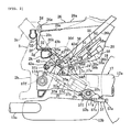
- FIGs. 1 to 10 illustrate to explain a straddle-type vehicle, such as a motorcycle, of the embodiment.
- a straddle-type vehicle has a body frame and a seat on which a rider can be seated straddling the body frame when being seated.
- the terms front, rear, left, and right as used in this embodiment indicate the front, rear, left, and right when viewed from a rider seated on a seat.
- the reference numeral 1 indicates a motorcycle which is generally structured as below.
- a head pipe 2a at the front end portion of a vehicle body frame 2 supports a front fork 3 in such a manner that the front fork 3 is steerable to the left and right.
- a front wheel 4 is pivotally supported at a lower end portion of the front fork 3 and the front wheel 4 is covered by a front fender 5 which is installed at the lower portion of the front fork 3.
- the upper portion of the front fork 3 is provided with a headlight unit 6, and a steering handle 7 is fixed to the upper end portion of the front fork 3.
- the vehicle body frame 2 has an engine unit 8 that is supported by being suspended by a front suspension bracket 9, a center suspension bracket 10, and a rear arm bracket portion 2b of the vehicle body frame 2.
- the engine unit 8 is connected to an intake system 12 and an exhaust system 13. Furthermore, a radiator unit 14 is provided at the front of the engine unit 8.
- the intake system 12 is covered, from the top thereof, by a frame cover 15 which is provided with an indicator 16 that indicates a vehicle condition.
- a lower portion of a left side wall of the engine unit 8 is provided with a side stand unit 21 that allows the motorcycle 1 to stand slightly tilted to the left.
- a rear arm 17 is supported by the rear arm bracket portion 2b of the vehicle body frame 2 in such a manner that it can swing upward and downward.
- a rear wheel 18 is supported by a rear end portion of the rear arm 17. Hydraulic braking systems 22 and 22 are used to brake the rear wheel 18 and the front wheel 4.
- a rear suspension 19 is disposed between the rear arm 17 and the rear arm bracket portion 2b.
- the rear suspension 19 is provided with a remote control-type operation characteristics adjuster 25.
- a fuel tank 20 is disposed on top of the rear suspension 19.
- a hydraulic control unit 22a of the braking system 22 is disposed in front of and diagonally upward from the fuel tank 20.
- a front seat 23a is disposed such that it covers, from the top, the hydraulic control unit 22a and the fuel tank 20.
- a rear seat 23b is disposed at the rear of the front seat 23a.
- a reference numeral 23c indicates a backrest for supporting a lower back of a rider.
- a rear fender 24 (vehicle body cover) which covers the rear wheel 18 from the top is disposed under the rear seat 23b.
- the engine unit 8 is a water-cooled 4-stroke V-type 4-cylinder type engine that is structured such that the left and right front cylinders 8a and left and right rear cylinders 8b form a V-bank in a longitudinal direction.
- the exhaust system 13 includes four exhaust pipes 13a that are connected with each of the cylinders of the engine unit 8 and extend to the rear.
- the exhaust system 13 has an exhaust chamber (capacity chamber) 13b that is shared by all cylinders and is connected with the respective exhaust pipes 13a, and left and right mufflers 13c that are connected with the left and right side walls of the exhaust chamber 13b and extend to the rear and diagonally upward on the left side and right side of the vehicle, respectively.
- the exhaust chamber 13b is disposed under the front portion of the rear arm 17 as well as in front of the rear wheel 18.
- the rear arm 17 includes a left arm main body (a first arm main body) 17a located to the left side (one side) in a vehicle width direction, and a right arm main body (a second arm main body) 17b located to the right side (the other side).
- the rear arm 17 has a cross portion 17c for connecting the arm main bodies 17a and 17b with each other at the front portions thereof, and a pivot portion 17d formed at the front end portion of the cross portion 17c.
- the left and right arm main bodies 17a and 17b each have cylindrical body structures and extend in the longitudinal direction of the vehicle.
- the left arm main body 17a is also used as a shaft case in which a rear wheel driving shaft 18a is inserted and housed.
- a diameter of the left arm main body 17a is larger than a diameter of the right arm main body 17b.
- the cross portion 17c forms a flat box shape and is provided with a substantially rectangular opening 17e that passes vertically through the cross portion 17c.
- the opening 17e is formed in such manner as to be offset from a vehicle longitudinal centerline A towards one side (left side) of the vehicle width direction only by a dimension C.
- the opening 17e houses therein a cushion unit 37 of the rear suspension 19.
- the pivot portion 17d has a pivot shaft 17f inserted and housed therein.
- the rear arm 17 is supported by the rear arm bracket portion 2b of the vehicle body frame 2 via the pivot shaft 17f such that it can swing upward and downward.
- the fuel tank 20 is disposed in such a manner as to be housed in a rear frame 26 which constitutes a part of the vehicle body frame 2.
- the rear frame 26 has left and right seat rails 26a and 26a which extend substantially horizontally in a longitudinal direction, and has left and right back stays 26b and 26b which are fixedly connected to the rear portions of the left and right seat rails 26a and 26a and which extend to the front and diagonally downward from the rear portions.
- the rear frame 26 substantially forms a Y-shape in a vehicle side view.
- the seat rail 26a forms a U-shape, the opening of which is facing down, in a cross-sectional view.
- the back stay 26b forms a rectangular shape in the cross-sectional view.
- respective front end portions and respective rear end portions of the left and right seat rails 26a and 26a are connected by front and rear cross members which extend in the vehicle width direction.
- the rear frame 26 forms a substantially rectangular frame shape in a plane view.
- each of the seat rails 26a of the rear frame 26 is detachably connected, by a bolt 26e, with a boss portion 2d formed at the middle portion of the left and right main frames 2c and 2c that extend to the rear and diagonally downward from the head pipe 2a.
- the front end portion of each of the back stays 26b is detachably connected to the rear arm bracket portion 2b.
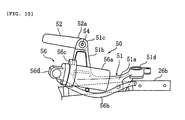
- the footrest 50 includes a footrest bracket 51 fixed to a support boss portion (bottom part) 26m formed so that it protrudes under the bottom surface of the back stay 26b, and a footrest main body 52 that is supported by the footrest bracket 51 in such a manner that it rotates.
- the footrest bracket 51 includes a base portion 51 a that touches the seat surface of the support boss portion 26m from below, and the base portion 51 a is tightened against the support boss portion 26m so that it is fixed by two bolts 53a, 53a that are inserted from below.
- a support leg portion 51 b at the rear end portion of the base portion 51 a is formed in such a manner as to protrude substantially horizontally to the outside in the vehicle width direction.
- a base portion 52a of the footrest main body 52 is inserted and housed within a forked support portion 51 c formed on the end of the support leg portion 51 b.
- the base portion 52a is supported by a support pin 54 inserted vertically so that it is able to tum between a retracted position in which it appears to be substantially adjacent to the rear fender 24 in a plane view and a use position in which it appears to protrude to the outside in the vehicle width direction.
- the rear fender 24 includes a mudguard 24a that covers the top of the rear wheel 18 and a fender main body 24b that covers the backrest 23c and left and right lower edge portions 23b' of the rear seat 23b from left and right outside edge portion 24a' of the mudguard 24a.
- a disposition portion D is formed in a section of the rear fender 24 that matches the position of the footrest 50. This disposition portion D is formed with an adjacent part to the connecting portion of the mudguard 24a and fender main body 24b that is indented to the inside and up in the vehicle direction.
- the support leg portion 51 b of the footrest bracket 51 passes through the wall surface from the boss portion 26m and extends to the outside in the vehicle width direction through the disposition portion D.
- the fuel tank 20 is a sealed plastic container that is formed, for instance, by blow molding, and has a top wall 20a, left and right side walls 20b and 20b, a front wall 20c, a rear wall 20d, and a bottom wall 20e.
- a front portion of the bottom wall 20e is provided with a recessed portion 20f to avoid interference with a link mechanism 38 to be described later.
- the fuel tank 20 is disposed between the left and right seat rails 26a and 26a, and the left and right back stays 26b and 26b. Also, an overhanging portion 20k that extends forward from the recessed portion 20f of the fuel tank 20 is disposed in a horizontal side portion 2g of a support plate 2f that has an L-shaped cross section via a flat damper 32 formed from an elastic member such as rubber. Moreover, the front wall 20c touches a vertical side portion 2i of the support plate 2f via a plate damper 33 formed from an elastic member such as rubber.
- the rear suspension 19 includes the cushion unit 37 and the link mechanism 38.
- the cushion unit 37 is disposed in such a manner that a shaft center B thereof aligns with the center of the opening 17e and passes through to the rear and diagonally downward from the rear arm bracket portion 2b.
- the cushion unit 37 when viewed from the side of the vehicle, intersects with the rear arm 17 and the greater portion of it overlaps with the rear arm 17.
- a piston 37b is inserted and disposed in a cylinder 37a in such a manner that it slides.
- the cushion unit 37 also includes a cushion main body 37d that allows a piston rod 37c that is connected to the piston 37b to protrude to the outside, and a coil-shaped cushion spring 37e that is disposed in such a way that it surrounds the cushion main body 37d.
- the purpose of the cushion spring 37e is to absorb the impact load from the rear wheel 18. Moreover, the cushion main body 37d produces a pressure damping force during compression and an extension damping force during extension, and has the function of dampening extension and retraction movements of the cushion spring 37e together with absorbing impact load.
- An end boss portion 37f of the piston rod 37c of the cushion main body 37d is linked by a support shaft 37h to a support boss portion 17g formed at the rear bottom edge of the opening 17e.
- a forked end boss portion 42a of a relay arm 42 of the link mechanism 38 is linked to a base end boss portion 37i of the cylinder 37a.
- a longitudinal center portion of the relay arm 42 is supported by a support shaft 42c to a bracket 43 in such a manner that it swings.
- the bracket 43 is U-shaped, and a bottom side portion 43b is fixed to a cross frame 2h by a bolt 43a.
- an end boss portion 44a of an arm 44 is linked to a forked base end boss portion 42d of the relay arm 42 by a link pin 44c.
- the arm 44 has a substantially triangular shape and widens in the vehicle width direction as its extends downward from the end boss portion 44a, and a base end boss portion 44d formed at a bottom side portion is supported by a support boss portion 17h formed at the rear arm 17 by a support shaft 44f.
- the recessed portion 20f formed at the front portion of the bottom wall 20e of the fuel tank 20 is formed so that it is offset from the vehicle centerline A towards the left side.
- a portion of the link mechanism 38 is positioned in the recessed portion 20f.
- the adjuster 25 includes a pressure damping force adjuster 56 with which the strength of the damping force produced by the cushion main body 37d during compression is adjusted, an extension damping force adjuster 57 with which the strength of the damping force during extension is adjusted, and an initial adjuster (spring force adjuster) 58 with which the initial value of the spring force produced by the cushion spring 37e is adjusted.
- the pressure damping force adjuster 56 has a structure in which a sub-tank 56a disposed in the disposition portion D on the right side is connected, by a hydraulic oil hose 56b, to a connection opening 37i' formed in the base end portion 37i of the cylinder 37a of the cushion main body 37d.
- the sub-tank 56a is in a position in which it inclines with its rear portion raised and in which it is positioned below the footrest bracket 51.
- the sub-tank 56a is fixed to the support leg portion 51 b of the footrest bracket 51 by a fixing band 56c in such a way that it can be installed and removed with a bolt 53b.
- An adjusting valve 56d that adjusts the pressure damping force through varying a hydraulic oil path area is formed on the rear end portion of the sub-tank 56a.
- the hydraulic oil hose 56b is connected to the top end portion of the adjusting valve 56d.
- an adjusting knob 56e that varies the path area is provided in the bottom end portion (opposite hose connection portion) of the adjusting valve 56d. When this adjusting knob 56e is rotated, the path area is varied and the pressuring damping force varies along with this.
- the initial adjuster 58 has a structure in which a cylinder mechanism 58a disposed in the disposition portion D' on the left side is connected by a hydraulic hose 57b to a drive portion 37m' formed in a spring bearing 37m of the cushion main body 37d.
- the cylinder mechanism 58a is in a position in which it inclines with its rear portion raised and in which it is positioned below the footrest bracket 51.
- the cylinder mechanism 58a is fixed to the lower surface of the support leg portion 51 b of the footrest bracket 51 by a bracket 58c in such a way that it can be installed and removed with a bolt 53c.
- An adjusting knob 58e is connected to the rear end portion of the cylinder mechanism 58a. When the adjusting knob 58e is rotated, the piston inside the cylinder mechanism 58a moves forward and backward, hydraulic pressure is transmitted to the drive portion 37m', and the pressurization of the cushion spring 37e is varied by the hydraulic pressure.
- a main body 57a of the extension damping force adjuster 57 is disposed on the bottom surface of the rear arm 17 and is connected to a bottom end portion of the cushion main body 37d by a linking member 57b. Moreover, an adjusting knob 57e is provided on the rear end portion of the main body 57a. By rotating the adjusting knob 57e, the damping pressure is varied by the hydraulic pressure produced by the main body 57a. Note that a structure in which the rotation of the adjusting knob 57e is transmitted to the cushion main body 37d by a wire is also possible.
- an adjusting knob 56e of the pressure damping force adjuster 56 and an adjusting knob 58e of the initial adjuster 58 when viewed from the rear of the vehicle, are disposed on the inside from an outer end surface 24' of the rear fender 24 in the vehicle width direction and below the footrest 50. Therefore, a rider in the rear seat mistaking the adjusting knobs 56e and 58e for footrests and placing their feet on them is reliably inhibited. Also, there is no danger of a rider in the rear seat placing their feet on the adjusting knobs 56e and 58e, and therefore the adjusting knobs 56e and 58e can be disposed in a location that is visible from the side of the vehicle. As a result, operability can be improved.
- the adjusting knobs 56e and 58e are attached to the footrest bracket 51. Therefore, a dedicated bracket for installation is unnecessary.
- the adjusting knobs 56e and 58e are disposed in a space E, E' that is surrounded by the disposition portion D, D' and the muffler 13c disposed such that is runs along the side of the vehicle. Therefore, the muffler 13c fulfills the function of blocking stones that fly up against the adjusting knobs. Thus, damage to the adjusting knobs 56e and 58e is inhibited.
- the rear fender 24 includes the mudguard 24a that covers the rear wheel from the top and the fender main body 24b that extends upward from the side edge portion 24a' of the mudguard in the vehicle width direction. Additionally, the disposition portion D, D' is formed in the boundary portion of the fender main body 24b and mudguard 24a. Also, the adjusting knobs 56e and 58e are disposed so that, when viewed from the side of the vehicle, they overlap with the disposition portion D, D' and are positioned below the footrest 50. Therefore, operability can be maintained while reliably inhibiting a rider in the rear seat from mistakenly placing their feet on the adjusting knobs.
- the footrest bracket 51 is attached to be in contact with the support boss portion 26m of the back stay 26b by the bolts 53a inserted from bottom to top. Therefore, even when the fuel tank 20 disposed on the inner side of the back stay 26b bulges to the outside, the bolts 53a will not scratch the fuel tank and the tank capacity can be maintained.
- the cylinder mechanism 58a and adjusting knob 58e of the initial adjuster 58 are disposed above the rear arm 17 and in the disposition portion D' on one side a in the vehicle width direction, and the sub-tank 56a and adjusting knob 56e of the pressure damping force adjuster 56 are disposed above the rear arm 17 in the disposition portion D on the other side b in the vehicle width direction. Therefore, the two adjusting knobs 58e and 56e can be disposed with good left to right balance, which also helps improve operability.
- the explanation of the embodiment involved a motorcycle.
- the present teaching can be applied to vehicles other than motorcycles such as straddle-type four-wheel vehicles for off-road use.
- a straddle-type vehicle comprising a vehicle body frame, a vehicle body cover covering a side of a rear portion of the vehicle body frame, a footrest on which a rider in a rear seat can place his/her feet and which is attached to the vehicle body frame and protrudes outwards from the vehicle body cover, a rear arm supported in a swingable manner by the vehicle body frame, and a rear suspension disposed between the rear arm and a vehicle body frame, the saddle-type vehicle being characterized in that the rear suspension includes an adjuster by which operation characteristics of the rear suspension are remotely operated and adjusted; and adjusting knobs of the adjuster that, when viewed from the rear of the vehicle, are disposed on the inside in the vehicle width direction from an outside end surface of the vehicle body cover as well as below the footrest.
- the footrest includes a footrest bracket attached to the vehicle body frame and a footrest main body attached to the footrest bracket, and the adjusting knobs are attached to the footrest bracket.
- the straddle-type vehicle further includes an exhaust system that includes a muffler disposed in such a manner as to pass through a side of the vehicle, and the adjusting knobs are positioned, when viewed from the rear of the vehicle, in such a manner as to be located in a space surrounded by the vehicle body cover, the footrest, and the muffler.
- the vehicle body cover includes a mudguard that covers a rear wheel from the top thereof and a fender main body that extends upward from a side edge portion of the mudguard in a vehicle width direction, a disposition portion is formed in a boundary portion of the fender main body and the mudguard, and the adjusting knobs are disposed in such a manner as to overlap with the disposition portion and be positioned below the footrest when viewed from the side of the vehicle.
- the vehicle body frame includes a rear portion frame and further includes a fuel tank disposed on the inside of the vehicle body frame, and the footrest bracket is attached to the bottom part of the rear portion frame.
- the footrest bracket is attached by a bolt that is inserted from bottom to top in the bottom part.
- the characteristics adjuster includes a spring force adjuster that adjusts a spring force of the rear suspension and a damping force adjuster that adjusts a damping force, an adjusting knob of the spring force adjuster is disposed above a rear arm and on one side in the vehicle width direction, and an adjusting knob of the damping force adjuster is disposed above the rear arm and on the other side in the vehicle width direction.
- the characteristics adjuster includes a damping force adjuster that adjusts a damping force of the rear suspension
- the damping force adjuster includes a sub-tank that is connected to the rear suspension by a hydraulic fluid path and stores hydraulic fluid, and an adjusting knob that is provided on the sub-tank and adjusts the area of the hydraulic fluid path, and the sub-tank and adjusting knob are disposed on the inside of the vehicle body cover outside end surface in the vehicle width direction as well as below the footrest.
- the characteristics adjuster includes a spring force adjuster that adjusts a spring force of the rear suspension
- the spring force adjuster includes a cylinder mechanism connected to the rear suspension by a hydraulic pressure path and an adjusting knob that is attached to the cylinder mechanism and which produces hydraulic pressure
- the cylinder mechanism and adjusting knob are disposed on the inside of the vehicle body cover outside end surface in the vehicle width direction as well as below the footrest.
- a rear suspension 19 includes an adjuster 25 in which the operating characteristics of the rear suspension can be adjusted through remote operation, and adjusting knobs 56e and 58e of the adjuster 25 are disposed, when view from the rear of a vehicle, on the inside in the vehicle width direction of an outer end surface 24' of a vehicle body cover 24 and under a footrest 50.
Landscapes
- Engineering & Computer Science (AREA)
- Mechanical Engineering (AREA)
- Axle Suspensions And Sidecars For Cycles (AREA)
Applications Claiming Priority (1)
| Application Number | Priority Date | Filing Date | Title |
|---|---|---|---|
| JP2007264952A JP2009090889A (ja) | 2007-10-10 | 2007-10-10 | 鞍乗型車両 |
Publications (3)
| Publication Number | Publication Date |
|---|---|
| EP2048074A2 true EP2048074A2 (de) | 2009-04-15 |
| EP2048074A3 EP2048074A3 (de) | 2011-08-24 |
| EP2048074B1 EP2048074B1 (de) | 2018-09-05 |
Family
ID=40256866
Family Applications (1)
| Application Number | Title | Priority Date | Filing Date |
|---|---|---|---|
| EP08017817.1A Active EP2048074B1 (de) | 2007-10-10 | 2008-10-10 | Dämpfereinstellung für Motorrad |
Country Status (2)
| Country | Link |
|---|---|
| EP (1) | EP2048074B1 (de) |
| JP (1) | JP2009090889A (de) |
Cited By (2)
| Publication number | Priority date | Publication date | Assignee | Title |
|---|---|---|---|---|
| CN102139726A (zh) * | 2011-02-25 | 2011-08-03 | 力帆实业(集团)股份有限公司 | 摩托车减震踏板 |
| US8474582B2 (en) | 2009-09-08 | 2013-07-02 | Yamaha Hatsudoki Kabushiki Kaisha | Cushion device and motorcycle |
Families Citing this family (2)
| Publication number | Priority date | Publication date | Assignee | Title |
|---|---|---|---|---|
| JP5328448B2 (ja) * | 2009-03-30 | 2013-10-30 | 本田技研工業株式会社 | 自動二輪車 |
| KR101081929B1 (ko) | 2011-03-07 | 2011-11-10 | 박기주 | 분전반 통합 감시 시스템 |
Citations (5)
| Publication number | Priority date | Publication date | Assignee | Title |
|---|---|---|---|---|
| US5348112A (en) | 1993-02-19 | 1994-09-20 | Works Performance Products, Inc. | Motorcycle height adjuster |
| EP0972703A2 (de) | 1998-07-17 | 2000-01-19 | Bayerische Motoren Werke Aktiengesellschaft, Patentabteilung AJ-3 | Einstelleinrichtung für ein Federbein eines Motorrads |
| US6044940A (en) | 1996-11-13 | 2000-04-04 | Marzocchi S.P.A. | Remote-controlled hydropneumatic shock absorber |
| WO2004104441A1 (ja) | 2003-05-22 | 2004-12-02 | Yamaha Hatsudoki Kabushiki Kaisha | 自動二輪車 |
| US7159699B1 (en) | 2003-05-21 | 2007-01-09 | Tine Jr Theodore J | Adjustable shock absorber |
Family Cites Families (1)
| Publication number | Priority date | Publication date | Assignee | Title |
|---|---|---|---|---|
| US3948543A (en) * | 1975-01-24 | 1976-04-06 | Macdonald John M | Motorcycle suspension system |
-
2007
- 2007-10-10 JP JP2007264952A patent/JP2009090889A/ja active Pending
-
2008
- 2008-10-10 EP EP08017817.1A patent/EP2048074B1/de active Active
Patent Citations (5)
| Publication number | Priority date | Publication date | Assignee | Title |
|---|---|---|---|---|
| US5348112A (en) | 1993-02-19 | 1994-09-20 | Works Performance Products, Inc. | Motorcycle height adjuster |
| US6044940A (en) | 1996-11-13 | 2000-04-04 | Marzocchi S.P.A. | Remote-controlled hydropneumatic shock absorber |
| EP0972703A2 (de) | 1998-07-17 | 2000-01-19 | Bayerische Motoren Werke Aktiengesellschaft, Patentabteilung AJ-3 | Einstelleinrichtung für ein Federbein eines Motorrads |
| US7159699B1 (en) | 2003-05-21 | 2007-01-09 | Tine Jr Theodore J | Adjustable shock absorber |
| WO2004104441A1 (ja) | 2003-05-22 | 2004-12-02 | Yamaha Hatsudoki Kabushiki Kaisha | 自動二輪車 |
Cited By (2)
| Publication number | Priority date | Publication date | Assignee | Title |
|---|---|---|---|---|
| US8474582B2 (en) | 2009-09-08 | 2013-07-02 | Yamaha Hatsudoki Kabushiki Kaisha | Cushion device and motorcycle |
| CN102139726A (zh) * | 2011-02-25 | 2011-08-03 | 力帆实业(集团)股份有限公司 | 摩托车减震踏板 |
Also Published As
| Publication number | Publication date |
|---|---|
| JP2009090889A (ja) | 2009-04-30 |
| EP2048074B1 (de) | 2018-09-05 |
| EP2048074A3 (de) | 2011-08-24 |
Similar Documents
| Publication | Publication Date | Title |
|---|---|---|
| JP4071577B2 (ja) | 自動二輪車等車両におけるリンク式フロントサスペンション装置 | |
| US6908092B2 (en) | Link type suspension for vehicle such as motorcycle | |
| US6357775B1 (en) | Bottom link type front wheel suspension for motorcycle | |
| EP1953077B1 (de) | Schwingarmaufhängung für ein Fahrzeug | |
| US6053272A (en) | Engine mount for saddle-seat vehicle | |
| JP4130395B2 (ja) | スイングアーム式懸架装置 | |
| JP2007203858A (ja) | 二輪車の後輪懸架装置 | |
| EP2048074B1 (de) | Dämpfereinstellung für Motorrad | |
| US10823253B2 (en) | Saddle-type vehicle | |
| US20020066611A1 (en) | Motorcycle vibration reduction apparatus | |
| US10933934B2 (en) | Saddle-type vehicle | |
| EP2048070B1 (de) | Grätschsitz-Fahrzeug | |
| JP2019018758A (ja) | 鞍乗り型車両の前部構造 | |
| US10077092B2 (en) | Saddle-ride type vehicle | |
| US20060283648A1 (en) | Vehicle-use transmission manipulating device | |
| JP5570376B2 (ja) | 鞍乗型乗物のステップステー構造 | |
| JP7753851B2 (ja) | 後輪懸架装置 | |
| US11535336B2 (en) | Saddle riding vehicle | |
| JP3158806U (ja) | 鞍乗型車両 | |
| EP0082496A1 (de) | Stossdämpfer für das Hinterrad eines Zweiradfahrzeuges | |
| JP3158805U (ja) | 鞍乗型車両 | |
| JP6008894B2 (ja) | 鞍乗り型車両 | |
| JP5889948B2 (ja) | 車両のフットレスト構造 | |
| JPH0141557B2 (de) | ||
| WO2025204119A1 (ja) | 鞍乗り型車両 |
Legal Events
| Date | Code | Title | Description |
|---|---|---|---|
| PUAI | Public reference made under article 153(3) epc to a published international application that has entered the european phase |
Free format text: ORIGINAL CODE: 0009012 |
|
| AK | Designated contracting states |
Kind code of ref document: A2 Designated state(s): AT BE BG CH CY CZ DE DK EE ES FI FR GB GR HR HU IE IS IT LI LT LU LV MC MT NL NO PL PT RO SE SI SK TR |
|
| AX | Request for extension of the european patent |
Extension state: AL BA MK RS |
|
| PUAL | Search report despatched |
Free format text: ORIGINAL CODE: 0009013 |
|
| AK | Designated contracting states |
Kind code of ref document: A3 Designated state(s): AT BE BG CH CY CZ DE DK EE ES FI FR GB GR HR HU IE IS IT LI LT LU LV MC MT NL NO PL PT RO SE SI SK TR |
|
| AX | Request for extension of the european patent |
Extension state: AL BA MK RS |
|
| RIC1 | Information provided on ipc code assigned before grant |
Ipc: B62K 25/28 20060101AFI20110721BHEP Ipc: B62K 11/04 20060101ALI20110721BHEP |
|
| 17P | Request for examination filed |
Effective date: 20111013 |
|
| AKX | Designation fees paid |
Designated state(s): AT BE BG CH CY CZ DE DK EE ES FI FR GB GR HR HU IE IS IT LI LT LU LV MC MT NL NO PL PT RO SE SI SK TR |
|
| REG | Reference to a national code |
Ref country code: DE Ref legal event code: R079 Ref document number: 602008056776 Country of ref document: DE Free format text: PREVIOUS MAIN CLASS: B62K0025280000 Ipc: B62K0025040000 |
|
| GRAP | Despatch of communication of intention to grant a patent |
Free format text: ORIGINAL CODE: EPIDOSNIGR1 |
|
| STAA | Information on the status of an ep patent application or granted ep patent |
Free format text: STATUS: GRANT OF PATENT IS INTENDED |
|
| RIC1 | Information provided on ipc code assigned before grant |
Ipc: B62K 25/04 20060101AFI20180430BHEP Ipc: B62K 11/04 20060101ALI20180430BHEP Ipc: B62K 25/28 20060101ALI20180430BHEP |
|
| INTG | Intention to grant announced |
Effective date: 20180524 |
|
| GRAS | Grant fee paid |
Free format text: ORIGINAL CODE: EPIDOSNIGR3 |
|
| GRAA | (expected) grant |
Free format text: ORIGINAL CODE: 0009210 |
|
| STAA | Information on the status of an ep patent application or granted ep patent |
Free format text: STATUS: THE PATENT HAS BEEN GRANTED |
|
| AK | Designated contracting states |
Kind code of ref document: B1 Designated state(s): AT BE BG CH CY CZ DE DK EE ES FI FR GB GR HR HU IE IS IT LI LT LU LV MC MT NL NO PL PT RO SE SI SK TR |
|
| REG | Reference to a national code |
Ref country code: GB Ref legal event code: FG4D |
|
| REG | Reference to a national code |
Ref country code: CH Ref legal event code: EP |
|
| REG | Reference to a national code |
Ref country code: AT Ref legal event code: REF Ref document number: 1037471 Country of ref document: AT Kind code of ref document: T Effective date: 20180915 |
|
| REG | Reference to a national code |
Ref country code: DE Ref legal event code: R096 Ref document number: 602008056776 Country of ref document: DE |
|
| REG | Reference to a national code |
Ref country code: IE Ref legal event code: FG4D |
|
| REG | Reference to a national code |
Ref country code: FR Ref legal event code: PLFP Year of fee payment: 11 |
|
| REG | Reference to a national code |
Ref country code: NL Ref legal event code: MP Effective date: 20180905 |
|
| REG | Reference to a national code |
Ref country code: LT Ref legal event code: MG4D |
|
| PG25 | Lapsed in a contracting state [announced via postgrant information from national office to epo] |
Ref country code: FI Free format text: LAPSE BECAUSE OF FAILURE TO SUBMIT A TRANSLATION OF THE DESCRIPTION OR TO PAY THE FEE WITHIN THE PRESCRIBED TIME-LIMIT Effective date: 20180905 Ref country code: GR Free format text: LAPSE BECAUSE OF FAILURE TO SUBMIT A TRANSLATION OF THE DESCRIPTION OR TO PAY THE FEE WITHIN THE PRESCRIBED TIME-LIMIT Effective date: 20181206 Ref country code: NO Free format text: LAPSE BECAUSE OF FAILURE TO SUBMIT A TRANSLATION OF THE DESCRIPTION OR TO PAY THE FEE WITHIN THE PRESCRIBED TIME-LIMIT Effective date: 20181205 Ref country code: BG Free format text: LAPSE BECAUSE OF FAILURE TO SUBMIT A TRANSLATION OF THE DESCRIPTION OR TO PAY THE FEE WITHIN THE PRESCRIBED TIME-LIMIT Effective date: 20181205 Ref country code: SE Free format text: LAPSE BECAUSE OF FAILURE TO SUBMIT A TRANSLATION OF THE DESCRIPTION OR TO PAY THE FEE WITHIN THE PRESCRIBED TIME-LIMIT Effective date: 20180905 Ref country code: LT Free format text: LAPSE BECAUSE OF FAILURE TO SUBMIT A TRANSLATION OF THE DESCRIPTION OR TO PAY THE FEE WITHIN THE PRESCRIBED TIME-LIMIT Effective date: 20180905 |
|
| REG | Reference to a national code |
Ref country code: AT Ref legal event code: MK05 Ref document number: 1037471 Country of ref document: AT Kind code of ref document: T Effective date: 20180905 |
|
| PG25 | Lapsed in a contracting state [announced via postgrant information from national office to epo] |
Ref country code: HR Free format text: LAPSE BECAUSE OF FAILURE TO SUBMIT A TRANSLATION OF THE DESCRIPTION OR TO PAY THE FEE WITHIN THE PRESCRIBED TIME-LIMIT Effective date: 20180905 Ref country code: LV Free format text: LAPSE BECAUSE OF FAILURE TO SUBMIT A TRANSLATION OF THE DESCRIPTION OR TO PAY THE FEE WITHIN THE PRESCRIBED TIME-LIMIT Effective date: 20180905 Ref country code: ES Free format text: LAPSE BECAUSE OF FAILURE TO SUBMIT A TRANSLATION OF THE DESCRIPTION OR TO PAY THE FEE WITHIN THE PRESCRIBED TIME-LIMIT Effective date: 20180905 |
|
| PG25 | Lapsed in a contracting state [announced via postgrant information from national office to epo] |
Ref country code: CZ Free format text: LAPSE BECAUSE OF FAILURE TO SUBMIT A TRANSLATION OF THE DESCRIPTION OR TO PAY THE FEE WITHIN THE PRESCRIBED TIME-LIMIT Effective date: 20180905 Ref country code: IS Free format text: LAPSE BECAUSE OF FAILURE TO SUBMIT A TRANSLATION OF THE DESCRIPTION OR TO PAY THE FEE WITHIN THE PRESCRIBED TIME-LIMIT Effective date: 20190105 Ref country code: PL Free format text: LAPSE BECAUSE OF FAILURE TO SUBMIT A TRANSLATION OF THE DESCRIPTION OR TO PAY THE FEE WITHIN THE PRESCRIBED TIME-LIMIT Effective date: 20180905 Ref country code: NL Free format text: LAPSE BECAUSE OF FAILURE TO SUBMIT A TRANSLATION OF THE DESCRIPTION OR TO PAY THE FEE WITHIN THE PRESCRIBED TIME-LIMIT Effective date: 20180905 Ref country code: RO Free format text: LAPSE BECAUSE OF FAILURE TO SUBMIT A TRANSLATION OF THE DESCRIPTION OR TO PAY THE FEE WITHIN THE PRESCRIBED TIME-LIMIT Effective date: 20180905 Ref country code: EE Free format text: LAPSE BECAUSE OF FAILURE TO SUBMIT A TRANSLATION OF THE DESCRIPTION OR TO PAY THE FEE WITHIN THE PRESCRIBED TIME-LIMIT Effective date: 20180905 Ref country code: AT Free format text: LAPSE BECAUSE OF FAILURE TO SUBMIT A TRANSLATION OF THE DESCRIPTION OR TO PAY THE FEE WITHIN THE PRESCRIBED TIME-LIMIT Effective date: 20180905 |
|
| PG25 | Lapsed in a contracting state [announced via postgrant information from national office to epo] |
Ref country code: SK Free format text: LAPSE BECAUSE OF FAILURE TO SUBMIT A TRANSLATION OF THE DESCRIPTION OR TO PAY THE FEE WITHIN THE PRESCRIBED TIME-LIMIT Effective date: 20180905 Ref country code: PT Free format text: LAPSE BECAUSE OF FAILURE TO SUBMIT A TRANSLATION OF THE DESCRIPTION OR TO PAY THE FEE WITHIN THE PRESCRIBED TIME-LIMIT Effective date: 20190105 |
|
| REG | Reference to a national code |
Ref country code: CH Ref legal event code: PL |
|
| REG | Reference to a national code |
Ref country code: DE Ref legal event code: R097 Ref document number: 602008056776 Country of ref document: DE |
|
| REG | Reference to a national code |
Ref country code: BE Ref legal event code: MM Effective date: 20181031 |
|
| PG25 | Lapsed in a contracting state [announced via postgrant information from national office to epo] |
Ref country code: LU Free format text: LAPSE BECAUSE OF NON-PAYMENT OF DUE FEES Effective date: 20181010 |
|
| PLBE | No opposition filed within time limit |
Free format text: ORIGINAL CODE: 0009261 |
|
| STAA | Information on the status of an ep patent application or granted ep patent |
Free format text: STATUS: NO OPPOSITION FILED WITHIN TIME LIMIT |
|
| REG | Reference to a national code |
Ref country code: IE Ref legal event code: MM4A |
|
| PG25 | Lapsed in a contracting state [announced via postgrant information from national office to epo] |
Ref country code: MC Free format text: LAPSE BECAUSE OF FAILURE TO SUBMIT A TRANSLATION OF THE DESCRIPTION OR TO PAY THE FEE WITHIN THE PRESCRIBED TIME-LIMIT Effective date: 20180905 Ref country code: DK Free format text: LAPSE BECAUSE OF FAILURE TO SUBMIT A TRANSLATION OF THE DESCRIPTION OR TO PAY THE FEE WITHIN THE PRESCRIBED TIME-LIMIT Effective date: 20180905 |
|
| 26N | No opposition filed |
Effective date: 20190606 |
|
| GBPC | Gb: european patent ceased through non-payment of renewal fee |
Effective date: 20181205 |
|
| PG25 | Lapsed in a contracting state [announced via postgrant information from national office to epo] |
Ref country code: SI Free format text: LAPSE BECAUSE OF FAILURE TO SUBMIT A TRANSLATION OF THE DESCRIPTION OR TO PAY THE FEE WITHIN THE PRESCRIBED TIME-LIMIT Effective date: 20180905 Ref country code: CH Free format text: LAPSE BECAUSE OF NON-PAYMENT OF DUE FEES Effective date: 20181031 Ref country code: LI Free format text: LAPSE BECAUSE OF NON-PAYMENT OF DUE FEES Effective date: 20181031 Ref country code: BE Free format text: LAPSE BECAUSE OF NON-PAYMENT OF DUE FEES Effective date: 20181031 |
|
| PG25 | Lapsed in a contracting state [announced via postgrant information from national office to epo] |
Ref country code: IE Free format text: LAPSE BECAUSE OF NON-PAYMENT OF DUE FEES Effective date: 20181010 |
|
| PG25 | Lapsed in a contracting state [announced via postgrant information from national office to epo] |
Ref country code: GB Free format text: LAPSE BECAUSE OF NON-PAYMENT OF DUE FEES Effective date: 20181205 |
|
| PG25 | Lapsed in a contracting state [announced via postgrant information from national office to epo] |
Ref country code: MT Free format text: LAPSE BECAUSE OF NON-PAYMENT OF DUE FEES Effective date: 20181010 |
|
| PG25 | Lapsed in a contracting state [announced via postgrant information from national office to epo] |
Ref country code: TR Free format text: LAPSE BECAUSE OF FAILURE TO SUBMIT A TRANSLATION OF THE DESCRIPTION OR TO PAY THE FEE WITHIN THE PRESCRIBED TIME-LIMIT Effective date: 20180905 |
|
| PG25 | Lapsed in a contracting state [announced via postgrant information from national office to epo] |
Ref country code: CY Free format text: LAPSE BECAUSE OF FAILURE TO SUBMIT A TRANSLATION OF THE DESCRIPTION OR TO PAY THE FEE WITHIN THE PRESCRIBED TIME-LIMIT Effective date: 20180905 Ref country code: HU Free format text: LAPSE BECAUSE OF FAILURE TO SUBMIT A TRANSLATION OF THE DESCRIPTION OR TO PAY THE FEE WITHIN THE PRESCRIBED TIME-LIMIT; INVALID AB INITIO Effective date: 20081010 |
|
| P01 | Opt-out of the competence of the unified patent court (upc) registered |
Effective date: 20230527 |
|
| PGFP | Annual fee paid to national office [announced via postgrant information from national office to epo] |
Ref country code: DE Payment date: 20251021 Year of fee payment: 18 |
|
| PGFP | Annual fee paid to national office [announced via postgrant information from national office to epo] |
Ref country code: IT Payment date: 20251024 Year of fee payment: 18 |
|
| PGFP | Annual fee paid to national office [announced via postgrant information from national office to epo] |
Ref country code: FR Payment date: 20251029 Year of fee payment: 18 |