EP2045894B1 - Motor vehicle lighting system - Google Patents
Motor vehicle lighting system Download PDFInfo
- Publication number
- EP2045894B1 EP2045894B1 EP20070113951 EP07113951A EP2045894B1 EP 2045894 B1 EP2045894 B1 EP 2045894B1 EP 20070113951 EP20070113951 EP 20070113951 EP 07113951 A EP07113951 A EP 07113951A EP 2045894 B1 EP2045894 B1 EP 2045894B1
- Authority
- EP
- European Patent Office
- Prior art keywords
- ballast
- time delay
- delay unit
- lighting device
- motor vehicles
- Prior art date
- Legal status (The legal status is an assumption and is not a legal conclusion. Google has not performed a legal analysis and makes no representation as to the accuracy of the status listed.)
- Active
Links
- 230000004913 activation Effects 0.000 claims description 2
- 238000004590 computer program Methods 0.000 claims description 2
- 230000009849 deactivation Effects 0.000 claims description 2
- 230000013011 mating Effects 0.000 description 4
- 238000010586 diagram Methods 0.000 description 2
- 238000000034 method Methods 0.000 description 1
- 230000002123 temporal effect Effects 0.000 description 1
- 229910052724 xenon Inorganic materials 0.000 description 1
- FHNFHKCVQCLJFQ-UHFFFAOYSA-N xenon atom Chemical compound [Xe] FHNFHKCVQCLJFQ-UHFFFAOYSA-N 0.000 description 1
Images


Classifications
-
- H—ELECTRICITY
- H02—GENERATION; CONVERSION OR DISTRIBUTION OF ELECTRIC POWER
- H02J—CIRCUIT ARRANGEMENTS OR SYSTEMS FOR SUPPLYING OR DISTRIBUTING ELECTRIC POWER; SYSTEMS FOR STORING ELECTRIC ENERGY
- H02J1/00—Circuit arrangements for dc mains or dc distribution networks
- H02J1/14—Balancing the load in a network
-
- B—PERFORMING OPERATIONS; TRANSPORTING
- B60—VEHICLES IN GENERAL
- B60R—VEHICLES, VEHICLE FITTINGS, OR VEHICLE PARTS, NOT OTHERWISE PROVIDED FOR
- B60R16/00—Electric or fluid circuits specially adapted for vehicles and not otherwise provided for; Arrangement of elements of electric or fluid circuits specially adapted for vehicles and not otherwise provided for
- B60R16/02—Electric or fluid circuits specially adapted for vehicles and not otherwise provided for; Arrangement of elements of electric or fluid circuits specially adapted for vehicles and not otherwise provided for electric constitutive elements
- B60R16/03—Electric or fluid circuits specially adapted for vehicles and not otherwise provided for; Arrangement of elements of electric or fluid circuits specially adapted for vehicles and not otherwise provided for electric constitutive elements for supply of electrical power to vehicle subsystems or for
-
- H—ELECTRICITY
- H02—GENERATION; CONVERSION OR DISTRIBUTION OF ELECTRIC POWER
- H02J—CIRCUIT ARRANGEMENTS OR SYSTEMS FOR SUPPLYING OR DISTRIBUTING ELECTRIC POWER; SYSTEMS FOR STORING ELECTRIC ENERGY
- H02J2310/00—The network for supplying or distributing electric power characterised by its spatial reach or by the load
- H02J2310/40—The network being an on-board power network, i.e. within a vehicle
- H02J2310/46—The network being an on-board power network, i.e. within a vehicle for ICE-powered road vehicles
Definitions
- the invention relates to a motor vehicle lighting system with a right and a left headlight, the headlights each having a gas discharge lamp as a light source.
- headlights are also referred to as xenon headlights.
- a special circuit arrangement is required, which is arranged in a so-called ballast.
- the two ballasts receive a switch-on command for the gas discharge lamp via a bus system from a vehicle electrical system control unit.
- a motor vehicle lighting system is for example from the DE 602 00 395 T2 known.
- the power and power consumption of the ballasts is many times higher than in normal operation. Since the two ballasts receive the switch-on commands at the same time when actuated via a bus system, the load on the vehicle electrical system from which the ballasts are electrically supplied is doubled during the switch-on phase. This high load can lead in particular to thermal problems.
- the object of the invention is therefore to develop a motor vehicle lighting system in which the electrical system load is significantly reduced. This object is solved by the features of claim 1.
- the adjoining subclaims relate to advantageous embodiments.
- a delay unit is integrated in the ballast of the left or right headlamp, which causes the switch-on command to be executed after receipt thereof only with a predetermined time delay ( ⁇ T).
- the time delay (.DELTA.T) is chosen so large that the one gas discharge lamp is only switched on when the switch-on of the other gas discharge lamp is at least almost completed.
- FIG. 1 shows a block diagram of a motor vehicle lighting system according to the invention. This includes the two headlights (left, right), each with a gas discharge lamp. Each headlamp is assigned a ballast for the operation of the gas discharge lamp. Not shown separately in this illustration, the actual igniter, which may be located directly on the gas discharge lamp, or may be integrated in the ballast.
- a switch-on command is generated via the vehicle electrical system control unit, which is sent simultaneously via the bus system (eg a LIN bus) to the two ballasts.
- the vehicle electrical system control unit which is sent simultaneously via the bus system (eg a LIN bus) to the two ballasts.
- a delay unit is integrated, which causes the turn-on after receiving the same only with a predetermined time delay (.DELTA.T) is executed.
- the delay unit can be designed as running within the ballast computer program.
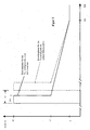
- FIG. 2 is the temporal behavior of the current consumption for the two ballasts shown.
- the high current switch-on phase which begins almost immediately with the execution of the switch-on command, is approximately 400 ⁇ s.
- the current consumption of the ballast is about 40 amps.
- the power consumption drops abruptly to about 15 amps and then drops after about 30s to an operating current of about 5 amps.
- FIG. 2 recognizable carried out the execution of the turn-on by the ballast for the right-hand headlamp only with a time delay of .DELTA.T, so that the high-current switch-on for the right ballast only begins when the high-current switch-on for the ballast of the left headlamp has already ended.
- a delay time is selected which is greater than the typical duration of the switch-on phases.
- the delay time is approx. 500 ⁇ s.
- ballast of the right headlamp has a delay unit.
- both ballasts have an integrated delay unit, wherein the delay units can then be activated or deactivated optionally by a signal which can be applied externally to the ballast.
- ballasts of identical design can be used, whereby the invention according to the invention asynchronous turning on the headlights is effected.
- the use of identical ballasts for the left and right headlights simplifies both the handling of the initial assembly as well as the spare parts assembly in case of repair.
- the ballasts preferably each have a coding connection (see FIG. 4 ), wherein the activation or deactivation of the delay unit takes place via the voltage potential applied externally to the coding terminal.
- This coding connection is preferably arranged in a connection plug, which also also includes the bus connection, the on-board supply connection (12V connection) and the ground connection.
- This connection plug is connected to a mating connector on the respective headlight connection cable.
- the coding connection is located at the mating connector of the connection cable for the right-hand headlight On-board voltage potential of 12V, while the coding connection at the mating connector of the connection cable for the left-hand headlamp is at ground potential.
- the coding ie the determination in which ballast, the delay unit is activated
- the coding is done in a simple manner automatically by connecting the connector plug with the respective mating connector of the headlight connection cable.
Description
Die Erfindung bezieht sich auf eine Kraftfahrzeuglichtanlage mit einem rechten und einen linken Scheinwerfer, wobei die Scheinwerfer jeweils eine Gasentladungslampe als Lichtquelle aufweisen. Derartige Scheinwerfer werden auch als Xenon-Scheinwerfer bezeichnet. Für den Betrieb der Gasentladungslampen ist eine spezielle Schaltungsanordnung erforderlich, die in einem sogenannten Vorschaltgerät angeordnet ist. Dabei empfangen die beiden Vorschaltgeräte über ein Bus-System von einem Bordnetz-Steuergerät einen Einschaltbefehl für die Gasentladungslampe. Eine derartige Kraftfahrzeuglichtanlage ist beispielsweise aus der
Während der Einschaltphase der Gasentladungslampen ist die Strom- und Leistungsaufnahme der Vorschaltgeräte um ein Vielfaches höher als im normalen Betrieb. Da die beiden Vorschaltgeräte bei einer Ansteuerung über ein Bus-System die Einschaltbefehle gleichzeitig empfangen, wird die Belastung des Fahrzeugbordnetzes, aus dem die Vorschaltgeräte elektrisch versorgt werden, während der Einschaltphase noch verdoppelt. Dabei kann diese hohe Belastung insbesondere zu thermischen Problemen führen.During the switch-on phase of the gas discharge lamps, the power and power consumption of the ballasts is many times higher than in normal operation. Since the two ballasts receive the switch-on commands at the same time when actuated via a bus system, the load on the vehicle electrical system from which the ballasts are electrically supplied is doubled during the switch-on phase. This high load can lead in particular to thermal problems.
Dokument
Aufgabe der Erfindung ist es daher eine Kraftfahrzeuglichtanlage zu entwickeln, bei der die Bordnetzbelastung deutlich verringert wird. Diese Aufgabe wird durch die Merkmale des Anspruches 1 gelöst. Die sich daran anschließenden Unteransprüche beziehen sich auf vorteilhafte Ausgestaltungen.The object of the invention is therefore to develop a motor vehicle lighting system in which the electrical system load is significantly reduced. This object is solved by the features of claim 1. The adjoining subclaims relate to advantageous embodiments.
Erfindungsgemäß ist in dem Vorschaltgerät des linken oder des rechten Scheinwerfers eine Verzögerungseinheit integriert ist, welche bewirkt, dass der Einschaltbefehl nach Erhalt desselben erst mit einer vorbestimmten zeitlichen Verzögerung (ΔT) ausgeführt wird. Dabei ist die zeitliche Verzögerung (ΔT) so groß gewählt, dass die eine Gasentladungslampe erst dann eingeschaltet wird, wenn die Einschaltphase der anderen Gasentladungslampe zumindest fast beendet ist. Durch das asynchrone Einschalten der beiden Gasentladungslampen wird somit die Bordnetzbelastung erheblich verringert, da das Bordnetz nicht mehr gleichzeitig mit der hohen Stromaufnahme durch die beiden Vorschaltgeräte während der Einschaltphase belastet wird.According to the invention, a delay unit is integrated in the ballast of the left or right headlamp, which causes the switch-on command to be executed after receipt thereof only with a predetermined time delay (ΔT). The time delay (.DELTA.T) is chosen so large that the one gas discharge lamp is only switched on when the switch-on of the other gas discharge lamp is at least almost completed. As a result of the asynchronous switching on of the two gas discharge lamps, the on-board network load is thus considerably reduced, since the vehicle electrical system is no longer loaded simultaneously with the high current consumption by the two ballasts during the switch-on phase.
Anhand der beigefügten Zeichnungen wird die Erfindung nachfolgend näher erläutert. Dabei zeigt:
- Fig. 1
- ein Blockschaltbild der Kraftfahrzeuglichtanlage,
- Fig. 2
- den zeitlichen Verlauf der Stromaufnahme durch die Vorschaltgeräte während des Einschaltens der Gasentladungslampen,
- Fig. 3
- eine Veranschaulichung des Ablaufes, der nach Erhalt des Einschaltbefehls durchlaufen wird,
- Fig.4
- eine schematische Darstellung eines Vorschaltgerätes mit seinen Anschlüssen, insbesondere mit dem erfindungsgemäßen Codier-Anschluss.
- Fig. 1
- a block diagram of the motor vehicle lighting system,
- Fig. 2
- the time course of the current consumption by the ballasts during the switching on of the gas discharge lamps,
- Fig. 3
- an illustration of the procedure which is passed after receiving the switch-on command,
- Figure 4
- a schematic representation of a ballast with its terminals, in particular with the coding connection according to the invention.
Sobald über den Lichtschalter beispielsweise das Signal "Abblendlicht Ein" erzeugt wird, wird über das Bordnetzsteuergerät ein Einschaltbefehl generiert, der über das Bus-System (z.B. ein LIN-Bus) gleichzeitig an die beiden Vorschaltgeräte gesendet wird. In der Ausführungsform gemäß
In
In der Ausführungsform gemäß
Zur Aktivierung oder Deaktivierung der Verzögerungseinheit weisen die Vorschaltgeräte vorzugsweise jeweils einen Codier-Anschluss (siehe
Die Codierung erfolgt so in einfacher Weise automatisch durch Verbindung des Anschluss-Steckers mit dem jeweiligen Gegenstecker des Scheinwerferanschlusskabels.The coding is done in a simple manner automatically by connecting the connector plug with the respective mating connector of the headlight connection cable.
Claims (6)
- Lighting device for motor vehicles with a right-hand and a left-hand headlamp,- wherein the headlamps each comprise a gas discharge lamp with an electronic ballast,- wherein the ballasts receive a starting signal for the gas discharge lamp by a vehicle electric system via a bus-system,characterized in that
a time delay unit is integrated in the ballast of the left-hand or right-hand headlamp, which causes the starting signal, once it has been received, to be executed only with a predetermined time delay (ΔT). - Lighting device for motor vehicles according to claim 1,
characterized in that
the time delay unit is embodied as a computer program running inside the ballast. - Lighting device for motor vehicles, according to claim 1,
characterized in that
the time delay unit is embodied as a timer module arranged inside the ballast. - Lighting device for motor vehicles according to one of the above claims,
characterized in that
the time delay unit has a layout effecting a time delay of more than 500µs. - Lighting device for motor vehicles according to one of the above claims,
wherein one time delay unit each is integrated in the ballast of the left-hand headlamp and in the ballast of the right-hand headlamp,
characterized in that
the time delay units can each be activated or deactivated by a signal sent from outside the ballast. - Lighting device for motor vehicles according to claim 5,
characterized in that
the two ballasts have one coded connection each,
wherein the activation or deactivation of the time delay unit is achieved by the voltage potential applied to the coded connection from outside.
Priority Applications (1)
| Application Number | Priority Date | Filing Date | Title |
|---|---|---|---|
| EP20070113951 EP2045894B1 (en) | 2007-08-07 | 2007-08-07 | Motor vehicle lighting system |
Applications Claiming Priority (1)
| Application Number | Priority Date | Filing Date | Title |
|---|---|---|---|
| EP20070113951 EP2045894B1 (en) | 2007-08-07 | 2007-08-07 | Motor vehicle lighting system |
Publications (2)
| Publication Number | Publication Date |
|---|---|
| EP2045894A1 EP2045894A1 (en) | 2009-04-08 |
| EP2045894B1 true EP2045894B1 (en) | 2015-04-22 |
Family
ID=39043186
Family Applications (1)
| Application Number | Title | Priority Date | Filing Date |
|---|---|---|---|
| EP20070113951 Active EP2045894B1 (en) | 2007-08-07 | 2007-08-07 | Motor vehicle lighting system |
Country Status (1)
| Country | Link |
|---|---|
| EP (1) | EP2045894B1 (en) |
Family Cites Families (5)
| Publication number | Priority date | Publication date | Assignee | Title |
|---|---|---|---|---|
| DE3436391A1 (en) * | 1984-06-22 | 1986-01-02 | Herbert 6720 Speyer Kripp | Method of operating the front lighting system of a motor vehicle and circuit arrangement for carrying out the method |
| JP2572408B2 (en) * | 1988-01-18 | 1997-01-16 | 株式会社日立製作所 | Power supply for vehicles |
| FR2829977B1 (en) | 2001-09-24 | 2003-12-12 | Valeo Vision | LIGHTING OR SIGNALING PROJECTOR WITH INTEGRATED CONTROLLER FOR VEHICLE AND LIGHTING OR SIGNALING SYSTEM PROVIDED WITH AT LEAST ONE SUCH PROJECTOR |
| DE10304636B4 (en) * | 2003-02-04 | 2015-02-12 | Hella Kgaa Hueck & Co. | System for energizing electrical consumers in a motor vehicle |
| KR100446102B1 (en) * | 2003-11-21 | 2004-08-25 | K.D.G.Eng | the appartus and method for synchronous lighting by one ballast with two bulb |
-
2007
- 2007-08-07 EP EP20070113951 patent/EP2045894B1/en active Active
Also Published As
| Publication number | Publication date |
|---|---|
| EP2045894A1 (en) | 2009-04-08 |
Similar Documents
| Publication | Publication Date | Title |
|---|---|---|
| DE4341058C1 (en) | Light control device for a motor vehicle | |
| DE60200395T2 (en) | Lighting or signaling headlight and method with at least one headlight | |
| EP0698527B1 (en) | Switching device for vehicle lighting | |
| DE19511755C1 (en) | Multiplex control of components or subsystems in motor vehicles | |
| DE10357293B4 (en) | A lamp control device and method of operating a lamp control device | |
| WO2011161156A1 (en) | Industrial truck comprising a work luminaire and method for activating and deactivating | |
| DE19739410C1 (en) | Electrical circuit for the network on board a motor vehicle | |
| EP0950564B1 (en) | Electronic blinker | |
| EP2045894B1 (en) | Motor vehicle lighting system | |
| DE4329860A1 (en) | Circuit arrangement for controlling different electrical loads in a motor vehicle | |
| DE19644292C2 (en) | Electronics unit for vehicles | |
| EP1052760A2 (en) | CAN bus-system with automatic switch-off of parts of the network in case of faults | |
| DE10304636B4 (en) | System for energizing electrical consumers in a motor vehicle | |
| DE102006058587A1 (en) | Electrical connection box | |
| DE19813595A1 (en) | Flashing light control device for providing trafficator or hazard warning signal for automobile | |
| DE4408959C1 (en) | Circuit for a system having an element which can be operated intermittently, in particular a motor-vehicle hazard warning system | |
| DE60310285T2 (en) | Device and method for supply control of an electrical load | |
| DE102011115221B4 (en) | Motor vehicle with several headlights | |
| DE102004027351B3 (en) | Circuit arrangement for operating an LED signal generator | |
| DE4030513A1 (en) | Vehicular flashing indicator reduces switch contact erosion - takes control current for load relay coils or switching transistors through contacts of direction indicator switch | |
| DE10236304A1 (en) | Circuit arrangement for control and monitoring of electrical lighting devices in trailer vehicles, has protective diode connected between load side connection of each power switch and common line | |
| EP0945308B1 (en) | Circuit arrangement for a vehicle electrical distribution centre | |
| DE102017101846A1 (en) | Device, system, method for configuring the device, method for operating the system, computer program product and computer-readable medium for the electrical control of at least one real electrical consumer of a motor vehicle | |
| DE10200250A1 (en) | Lighting device for automobile has emergency operation function unit incorporated in electronic control unit | |
| DE19803806B4 (en) | Circuit arrangement for electrical consumers in a motor vehicle |
Legal Events
| Date | Code | Title | Description |
|---|---|---|---|
| PUAI | Public reference made under article 153(3) epc to a published international application that has entered the european phase |
Free format text: ORIGINAL CODE: 0009012 |
|
| 17P | Request for examination filed |
Effective date: 20080508 |
|
| AK | Designated contracting states |
Kind code of ref document: A1 Designated state(s): AT BE BG CH CY CZ DE DK EE ES FI FR GB GR HU IE IS IT LI LT LU LV MC MT NL PL PT RO SE SI SK TR |
|
| AX | Request for extension of the european patent |
Extension state: AL BA HR MK RS |
|
| AKX | Designation fees paid |
Designated state(s): AT BE BG CH CY CZ DE DK EE ES FI FR GB GR HU IE IS IT LI LT LU LV MC MT NL PL PT RO SE SI SK TR |
|
| GRAP | Despatch of communication of intention to grant a patent |
Free format text: ORIGINAL CODE: EPIDOSNIGR1 |
|
| INTG | Intention to grant announced |
Effective date: 20141223 |
|
| GRAS | Grant fee paid |
Free format text: ORIGINAL CODE: EPIDOSNIGR3 |
|
| GRAA | (expected) grant |
Free format text: ORIGINAL CODE: 0009210 |
|
| AK | Designated contracting states |
Kind code of ref document: B1 Designated state(s): AT BE BG CH CY CZ DE DK EE ES FI FR GB GR HU IE IS IT LI LT LU LV MC MT NL PL PT RO SE SI SK TR |
|
| REG | Reference to a national code |
Ref country code: GB Ref legal event code: FG4D Free format text: NOT ENGLISH |
|
| REG | Reference to a national code |
Ref country code: CH Ref legal event code: EP |
|
| REG | Reference to a national code |
Ref country code: AT Ref legal event code: REF Ref document number: 723763 Country of ref document: AT Kind code of ref document: T Effective date: 20150515 |
|
| REG | Reference to a national code |
Ref country code: IE Ref legal event code: FG4D Free format text: LANGUAGE OF EP DOCUMENT: GERMAN |
|
| REG | Reference to a national code |
Ref country code: DE Ref legal event code: R096 Ref document number: 502007013883 Country of ref document: DE Effective date: 20150603 |
|
| REG | Reference to a national code |
Ref country code: NL Ref legal event code: VDEP Effective date: 20150422 |
|
| REG | Reference to a national code |
Ref country code: LT Ref legal event code: MG4D |
|
| PG25 | Lapsed in a contracting state [announced via postgrant information from national office to epo] |
Ref country code: NL Free format text: LAPSE BECAUSE OF FAILURE TO SUBMIT A TRANSLATION OF THE DESCRIPTION OR TO PAY THE FEE WITHIN THE PRESCRIBED TIME-LIMIT Effective date: 20150422 |
|
| PG25 | Lapsed in a contracting state [announced via postgrant information from national office to epo] |
Ref country code: PT Free format text: LAPSE BECAUSE OF FAILURE TO SUBMIT A TRANSLATION OF THE DESCRIPTION OR TO PAY THE FEE WITHIN THE PRESCRIBED TIME-LIMIT Effective date: 20150824 Ref country code: LT Free format text: LAPSE BECAUSE OF FAILURE TO SUBMIT A TRANSLATION OF THE DESCRIPTION OR TO PAY THE FEE WITHIN THE PRESCRIBED TIME-LIMIT Effective date: 20150422 Ref country code: FI Free format text: LAPSE BECAUSE OF FAILURE TO SUBMIT A TRANSLATION OF THE DESCRIPTION OR TO PAY THE FEE WITHIN THE PRESCRIBED TIME-LIMIT Effective date: 20150422 Ref country code: ES Free format text: LAPSE BECAUSE OF FAILURE TO SUBMIT A TRANSLATION OF THE DESCRIPTION OR TO PAY THE FEE WITHIN THE PRESCRIBED TIME-LIMIT Effective date: 20150422 |
|
| PG25 | Lapsed in a contracting state [announced via postgrant information from national office to epo] |
Ref country code: LV Free format text: LAPSE BECAUSE OF FAILURE TO SUBMIT A TRANSLATION OF THE DESCRIPTION OR TO PAY THE FEE WITHIN THE PRESCRIBED TIME-LIMIT Effective date: 20150422 Ref country code: IS Free format text: LAPSE BECAUSE OF FAILURE TO SUBMIT A TRANSLATION OF THE DESCRIPTION OR TO PAY THE FEE WITHIN THE PRESCRIBED TIME-LIMIT Effective date: 20150822 Ref country code: GR Free format text: LAPSE BECAUSE OF FAILURE TO SUBMIT A TRANSLATION OF THE DESCRIPTION OR TO PAY THE FEE WITHIN THE PRESCRIBED TIME-LIMIT Effective date: 20150723 |
|
| REG | Reference to a national code |
Ref country code: DE Ref legal event code: R097 Ref document number: 502007013883 Country of ref document: DE |
|
| PG25 | Lapsed in a contracting state [announced via postgrant information from national office to epo] |
Ref country code: DK Free format text: LAPSE BECAUSE OF FAILURE TO SUBMIT A TRANSLATION OF THE DESCRIPTION OR TO PAY THE FEE WITHIN THE PRESCRIBED TIME-LIMIT Effective date: 20150422 Ref country code: EE Free format text: LAPSE BECAUSE OF FAILURE TO SUBMIT A TRANSLATION OF THE DESCRIPTION OR TO PAY THE FEE WITHIN THE PRESCRIBED TIME-LIMIT Effective date: 20150422 |
|
| PLBE | No opposition filed within time limit |
Free format text: ORIGINAL CODE: 0009261 |
|
| STAA | Information on the status of an ep patent application or granted ep patent |
Free format text: STATUS: NO OPPOSITION FILED WITHIN TIME LIMIT |
|
| PG25 | Lapsed in a contracting state [announced via postgrant information from national office to epo] |
Ref country code: CZ Free format text: LAPSE BECAUSE OF FAILURE TO SUBMIT A TRANSLATION OF THE DESCRIPTION OR TO PAY THE FEE WITHIN THE PRESCRIBED TIME-LIMIT Effective date: 20150422 Ref country code: SK Free format text: LAPSE BECAUSE OF FAILURE TO SUBMIT A TRANSLATION OF THE DESCRIPTION OR TO PAY THE FEE WITHIN THE PRESCRIBED TIME-LIMIT Effective date: 20150422 Ref country code: PL Free format text: LAPSE BECAUSE OF FAILURE TO SUBMIT A TRANSLATION OF THE DESCRIPTION OR TO PAY THE FEE WITHIN THE PRESCRIBED TIME-LIMIT Effective date: 20150422 Ref country code: RO Free format text: LAPSE BECAUSE OF NON-PAYMENT OF DUE FEES Effective date: 20150422 |
|
| 26N | No opposition filed |
Effective date: 20160125 |
|
| PG25 | Lapsed in a contracting state [announced via postgrant information from national office to epo] |
Ref country code: LU Free format text: LAPSE BECAUSE OF FAILURE TO SUBMIT A TRANSLATION OF THE DESCRIPTION OR TO PAY THE FEE WITHIN THE PRESCRIBED TIME-LIMIT Effective date: 20150807 Ref country code: MC Free format text: LAPSE BECAUSE OF FAILURE TO SUBMIT A TRANSLATION OF THE DESCRIPTION OR TO PAY THE FEE WITHIN THE PRESCRIBED TIME-LIMIT Effective date: 20150422 |
|
| REG | Reference to a national code |
Ref country code: CH Ref legal event code: PL |
|
| PG25 | Lapsed in a contracting state [announced via postgrant information from national office to epo] |
Ref country code: LI Free format text: LAPSE BECAUSE OF NON-PAYMENT OF DUE FEES Effective date: 20150831 Ref country code: IT Free format text: LAPSE BECAUSE OF FAILURE TO SUBMIT A TRANSLATION OF THE DESCRIPTION OR TO PAY THE FEE WITHIN THE PRESCRIBED TIME-LIMIT Effective date: 20150422 Ref country code: CH Free format text: LAPSE BECAUSE OF NON-PAYMENT OF DUE FEES Effective date: 20150831 |
|
| PG25 | Lapsed in a contracting state [announced via postgrant information from national office to epo] |
Ref country code: SI Free format text: LAPSE BECAUSE OF FAILURE TO SUBMIT A TRANSLATION OF THE DESCRIPTION OR TO PAY THE FEE WITHIN THE PRESCRIBED TIME-LIMIT Effective date: 20150422 |
|
| REG | Reference to a national code |
Ref country code: IE Ref legal event code: MM4A |
|
| REG | Reference to a national code |
Ref country code: FR Ref legal event code: PLFP Year of fee payment: 10 |
|
| PG25 | Lapsed in a contracting state [announced via postgrant information from national office to epo] |
Ref country code: IE Free format text: LAPSE BECAUSE OF NON-PAYMENT OF DUE FEES Effective date: 20150807 |
|
| REG | Reference to a national code |
Ref country code: AT Ref legal event code: MM01 Ref document number: 723763 Country of ref document: AT Kind code of ref document: T Effective date: 20150807 |
|
| PG25 | Lapsed in a contracting state [announced via postgrant information from national office to epo] |
Ref country code: AT Free format text: LAPSE BECAUSE OF NON-PAYMENT OF DUE FEES Effective date: 20150807 |
|
| PG25 | Lapsed in a contracting state [announced via postgrant information from national office to epo] |
Ref country code: MT Free format text: LAPSE BECAUSE OF FAILURE TO SUBMIT A TRANSLATION OF THE DESCRIPTION OR TO PAY THE FEE WITHIN THE PRESCRIBED TIME-LIMIT Effective date: 20150422 |
|
| PG25 | Lapsed in a contracting state [announced via postgrant information from national office to epo] |
Ref country code: HU Free format text: LAPSE BECAUSE OF FAILURE TO SUBMIT A TRANSLATION OF THE DESCRIPTION OR TO PAY THE FEE WITHIN THE PRESCRIBED TIME-LIMIT; INVALID AB INITIO Effective date: 20070807 Ref country code: BG Free format text: LAPSE BECAUSE OF FAILURE TO SUBMIT A TRANSLATION OF THE DESCRIPTION OR TO PAY THE FEE WITHIN THE PRESCRIBED TIME-LIMIT Effective date: 20150422 |
|
| PG25 | Lapsed in a contracting state [announced via postgrant information from national office to epo] |
Ref country code: CY Free format text: LAPSE BECAUSE OF FAILURE TO SUBMIT A TRANSLATION OF THE DESCRIPTION OR TO PAY THE FEE WITHIN THE PRESCRIBED TIME-LIMIT Effective date: 20150422 Ref country code: SE Free format text: LAPSE BECAUSE OF FAILURE TO SUBMIT A TRANSLATION OF THE DESCRIPTION OR TO PAY THE FEE WITHIN THE PRESCRIBED TIME-LIMIT Effective date: 20150422 |
|
| REG | Reference to a national code |
Ref country code: FR Ref legal event code: PLFP Year of fee payment: 11 |
|
| PG25 | Lapsed in a contracting state [announced via postgrant information from national office to epo] |
Ref country code: BE Free format text: LAPSE BECAUSE OF NON-PAYMENT OF DUE FEES Effective date: 20150831 |
|
| PG25 | Lapsed in a contracting state [announced via postgrant information from national office to epo] |
Ref country code: TR Free format text: LAPSE BECAUSE OF FAILURE TO SUBMIT A TRANSLATION OF THE DESCRIPTION OR TO PAY THE FEE WITHIN THE PRESCRIBED TIME-LIMIT Effective date: 20150422 |
|
| REG | Reference to a national code |
Ref country code: DE Ref legal event code: R081 Ref document number: 502007013883 Country of ref document: DE Owner name: HELLA GMBH & CO. KGAA, DE Free format text: FORMER OWNER: HELLA KGAA HUECK & CO., 59557 LIPPSTADT, DE |
|
| REG | Reference to a national code |
Ref country code: FR Ref legal event code: PLFP Year of fee payment: 12 |
|
| PGFP | Annual fee paid to national office [announced via postgrant information from national office to epo] |
Ref country code: FR Payment date: 20210714 Year of fee payment: 15 |
|
| PGFP | Annual fee paid to national office [announced via postgrant information from national office to epo] |
Ref country code: GB Payment date: 20210701 Year of fee payment: 15 |
|
| REG | Reference to a national code |
Ref country code: DE Ref legal event code: R084 Ref document number: 502007013883 Country of ref document: DE |
|
| GBPC | Gb: european patent ceased through non-payment of renewal fee |
Effective date: 20220807 |
|
| PG25 | Lapsed in a contracting state [announced via postgrant information from national office to epo] |
Ref country code: FR Free format text: LAPSE BECAUSE OF NON-PAYMENT OF DUE FEES Effective date: 20220831 |
|
| PG25 | Lapsed in a contracting state [announced via postgrant information from national office to epo] |
Ref country code: GB Free format text: LAPSE BECAUSE OF NON-PAYMENT OF DUE FEES Effective date: 20220807 |
|
| PGFP | Annual fee paid to national office [announced via postgrant information from national office to epo] |
Ref country code: DE Payment date: 20230613 Year of fee payment: 17 |