EP1052760A2 - CAN bus-system with automatic switch-off of parts of the network in case of faults - Google Patents
CAN bus-system with automatic switch-off of parts of the network in case of faults Download PDFInfo
- Publication number
- EP1052760A2 EP1052760A2 EP00250141A EP00250141A EP1052760A2 EP 1052760 A2 EP1052760 A2 EP 1052760A2 EP 00250141 A EP00250141 A EP 00250141A EP 00250141 A EP00250141 A EP 00250141A EP 1052760 A2 EP1052760 A2 EP 1052760A2
- Authority
- EP
- European Patent Office
- Prior art keywords
- network
- subnetworks
- monitoring device
- bus system
- sub
- Prior art date
- Legal status (The legal status is an assumption and is not a legal conclusion. Google has not performed a legal analysis and makes no representation as to the accuracy of the status listed.)
- Withdrawn
Links
Images
Classifications
-
- H—ELECTRICITY
- H02—GENERATION; CONVERSION OR DISTRIBUTION OF ELECTRIC POWER
- H02J—CIRCUIT ARRANGEMENTS OR SYSTEMS FOR SUPPLYING OR DISTRIBUTING ELECTRIC POWER; SYSTEMS FOR STORING ELECTRIC ENERGY
- H02J1/00—Circuit arrangements for dc mains or dc distribution networks
- H02J1/14—Balancing the load in a network
-
- H—ELECTRICITY
- H04—ELECTRIC COMMUNICATION TECHNIQUE
- H04L—TRANSMISSION OF DIGITAL INFORMATION, e.g. TELEGRAPHIC COMMUNICATION
- H04L12/00—Data switching networks
- H04L12/28—Data switching networks characterised by path configuration, e.g. LAN [Local Area Networks] or WAN [Wide Area Networks]
- H04L12/40—Bus networks
- H04L12/40006—Architecture of a communication node
-
- H—ELECTRICITY
- H04—ELECTRIC COMMUNICATION TECHNIQUE
- H04L—TRANSMISSION OF DIGITAL INFORMATION, e.g. TELEGRAPHIC COMMUNICATION
- H04L12/00—Data switching networks
- H04L12/28—Data switching networks characterised by path configuration, e.g. LAN [Local Area Networks] or WAN [Wide Area Networks]
- H04L12/46—Interconnection of networks
-
- H—ELECTRICITY
- H04—ELECTRIC COMMUNICATION TECHNIQUE
- H04L—TRANSMISSION OF DIGITAL INFORMATION, e.g. TELEGRAPHIC COMMUNICATION
- H04L69/00—Network arrangements, protocols or services independent of the application payload and not provided for in the other groups of this subclass
- H04L69/40—Network arrangements, protocols or services independent of the application payload and not provided for in the other groups of this subclass for recovering from a failure of a protocol instance or entity, e.g. service redundancy protocols, protocol state redundancy or protocol service redirection
-
- H—ELECTRICITY
- H04—ELECTRIC COMMUNICATION TECHNIQUE
- H04L—TRANSMISSION OF DIGITAL INFORMATION, e.g. TELEGRAPHIC COMMUNICATION
- H04L12/00—Data switching networks
- H04L12/28—Data switching networks characterised by path configuration, e.g. LAN [Local Area Networks] or WAN [Wide Area Networks]
- H04L12/40—Bus networks
- H04L2012/40208—Bus networks characterized by the use of a particular bus standard
- H04L2012/40215—Controller Area Network CAN
-
- H—ELECTRICITY
- H04—ELECTRIC COMMUNICATION TECHNIQUE
- H04L—TRANSMISSION OF DIGITAL INFORMATION, e.g. TELEGRAPHIC COMMUNICATION
- H04L12/00—Data switching networks
- H04L12/28—Data switching networks characterised by path configuration, e.g. LAN [Local Area Networks] or WAN [Wide Area Networks]
- H04L12/40—Bus networks
- H04L2012/40267—Bus for use in transportation systems
- H04L2012/40273—Bus for use in transportation systems the transportation system being a vehicle
Definitions
- the invention relates to a CAN bus system for a motor vehicle with one in several Subnetwork structured CAN network.
- CAN bus system controller area network
- the CAN bus system comprises a bus line connecting several CAN nodes, which consists of two parallel lines CAN-Low and CAN-High is formed.
- the CAN bus system is generally relatively insensitive to interference on one of the two lines CAN-Low or CAN-High, the interference in Form of an interruption, a short circuit to ground or a short circuit against supply voltage can occur.
- faults occur on both lines, so data traffic is no longer possible because of the access procedure of the CAN bus system requires that the CAN low and CAN high connections all CAN nodes are galvanically connected to each other. Such Faults can be caused in particular by an accident.
- US Pat. No. 5,818,673 is a power distribution system for a motor vehicle known that a variety of power distribution sections for power supply electrical loads.
- the power supply sections are each via electrical lines with electricity from an alternator and a battery supply device supplies and conduct the electricity via electrical branch lines to the electrical loads.
- the power supply sections are equipped with a variety of current detectors to detect the Stroms in the electrical lines and branch lines, with several switches to interrupt the connection between the electrical lines and Branch lines on the one hand and the electrical loads on the other hand and with one Control unit for controlling the switch provided, the control unit with connected to the current detectors and when an abnormal current value occurs in one of the electrical lines or branch lines Disconnects the line from the rest of the power distribution system.
- This well known System can cause malfunction of all electrical components in the event prevent a fault caused by an accident.
- the system is however relatively complex and correspondingly expensive.
- the object of the present invention is to provide a CAN bus system to create the type mentioned, which in the event of a fault, in particular in the case a short circuit caused by an accident, at least partially functional remains, this task being accomplished in a relatively inexpensive manner shall be.
- each subnet has a switch by which it can be disconnected from the rest of the CAN network a common monitoring device is assigned to the subnets communication, which is connected to all subnetworks via a transceiver monitored on the subnets and if a fault occurs in one the subnetworks the subnetwork which has the fault by means of this subnetwork disconnected assigned switch from the rest of the CAN network.
- the solution according to the invention is characterized in that a generic CAN bus system supplemented with just a few additional components and is therefore improved in a comparatively cost-effective manner in that that when a malfunction occurs, an automatic separation of the from the malfunction affected power supply and thus the functionality of the rest CAN network remains intact. It is also advantageous that in normal operation of the CAN bus systems according to the invention require no additional computing power becomes.
- the monitoring device of the CAN bus system according to the invention can preferably have a bus controller in the form of a microcontroller.
- the monitoring device if a malfunction occurs, switch off the subnets one after the other and one or more test messages each via the rest of the CAN network sends, the continuation of the shutdown process is ended and that Subnet currently switched off remains disconnected as soon as the monitoring device determines that the test message or test messages are correct have been sent and received.
- An alternative embodiment of the CAN bus system according to the invention is characterized in that the monitoring device when a Fault switches off all subnets and tests the subnets one after the other, after the test of all subnetworks have been completed, the switches of those subnetworks be closed again, in which no malfunction was found.
- switches of the subnets each have a relay and two switching contacts, one of which Switch contact in the CAN low line and the other switch contact in the CAN high line of the subnetwork is arranged, and wherein the relay via a Control line is connected to the monitoring device.
- the CAN network can preferably be divided into four subnets To be arranged.
- This configuration enables four areas of the To differentiate the motor vehicle from one another, preferably the areas at the front left, front right, rear left and rear right, so that in a unilateral rear-end collision if applicable, the areas not affected by this electrical components of the motor vehicle continue to function stay.
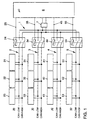
- the schematically shown CAN bus system comprises one of two in parallel Lines CAN low and CAN high formed bidirectional bus line 1, from the go off four branches 2, 3, 4 and 5.
- Each branch defines a subnet, whereby the first subnet 20 the front left area of the motor vehicle, the second Subnet 30 the front right area of the motor vehicle, the third subnet 40 the rear left area of the motor vehicle and the fourth subnet 50 is assigned to the rear right area of the motor vehicle.
- Any subnet has several connection points, so-called CAN nodes 21, 22, 23; 31, 32, 33; 41, 42, 43; 51, 52, 53 on the various vehicle lights such as the Flashing light, the low beam, the high beam, the parking light, the tail light, the Brake lights, etc. are assigned.
- each of the subnetworks 20, 30, 40, 50 has a switch 24, 34, 44 or 54, through which it can be separated from the rest of the CAN network can. In the normal state, all switches 24, 34, 44, 54 are closed.
- the Switches are designed so that bidirectional data traffic is possible when a switch is opened, both lines of the respective sub-network 20, 30, 40 or 50 are separated.
- the switches 24, 34, 44, 54 from a relay and two switch contacts, the one switch contact in the CAN low line and the other switch contact in the CAN high line of the respective subnetwork 20, 30, 40 or 50 is arranged.
- the relay of each switch is connected to a control line 25, 35, 45 or 55
- Monitoring device 6 connected to a bus controller in the form of a Has microcontroller and a transceiver 7 with the CAN low line and the CAN high line of bus line 1 is connected.
- a bus controller in the form of a Has microcontroller and a transceiver 7 with the CAN low line and the CAN high line of bus line 1 is connected.
- the bus controller monitors the communication on the CAN bus and its Subnets 20, 30, 40, 50. Is the communication disrupted, for example because of an accident in one of the subnets 20, 30, 40, 50 or in one of the CAN nodes 21, 22, 23; 31, 32, 33; 41, 42, 43; 51, 52, 53 a short to ground or is present against supply voltage, this fault is resolved by Bus controller of the monitoring device 6 detects and the relevant subnet automatically disconnected from the rest of the CAN network using the assigned switch. The shutdown is preferably carried out in such a way that the monitoring device 6 the subnets one after the other when a fault is detected 20, 30, 40, 50 switches off and sends test messages via the rest of the CAN network. If these test messages can be sent and received correctly, then the subnet currently disconnected is the faulty one. This subnet remains then disconnected from the rest of the CAN network, while data traffic over the intact rest of the CAN network can continue to run.
- a faulty subnet can also be switched off in this way take place that the monitoring device 6 all upon detection of a fault Subnets 20, 30, 40, 50 switches off and then the subnets one after the other tests, the switches after completion of the test of all subnets 20, 30, 40, 50 those subnets are closed again, in which no fault is found has been.
Abstract
Description
Die Erfindung betrifft ein CAN-Bus-System für ein Kraftfahrzeug mit einem in mehrere Teilnetze gegliederten CAN-Netz.The invention relates to a CAN bus system for a motor vehicle with one in several Subnetwork structured CAN network.
Zur Steigerung des Fahrkomforts sowie der Fahrsicherheit werden in Kraftfahrzeugen
immer mehr elektrische und elektronische Systeme verwendet. Um den
Umfang der dafür erforderlichen Kabelbäume zu verringern oder zumindest zu
begrenzen werden im Kraftfahrzeugbau zunehmend Bus-Strukturen eingesetzt.
Ein eigens für den Einsatz in Kraftfahrzeugen entwickeltes Bus-System ist das
sogenannte CAN-Bus-System (CAN = controller area network). Das CAN-Bus-System
umfaßt eine mehrere CAN-Knoten verbindende Busleitung, die aus zwei
parallelen Leitungen CAN-Low und CAN-High gebildet ist. Hinsichtlich des genauen
Aufbaus und der Funktionsweise eines CAN-Bus-Systems wird auf die
Zeitschrift ELRAD, 1991, Heft 1, Seiten 42-66 und die DE 41 26 850 A1 verwiesen.To increase driving comfort and driving safety are used in motor vehicles
more and more electrical and electronic systems are used. To the
To reduce the scope of the required wiring harnesses or at least to
limit, bus structures are increasingly being used in motor vehicle construction.
This is a bus system specially developed for use in motor vehicles
So-called CAN bus system (CAN = controller area network). The CAN bus system
comprises a bus line connecting several CAN nodes, which consists of two
parallel lines CAN-Low and CAN-High is formed. With regard to the exact
The structure and functionality of a CAN bus system is based on the
Journal ELRAD, 1991,
Das CAN-Bus-System ist im allgemeinen relativ unempfindlich gegen Störungen an einer der beiden Leitungen CAN-Low oder CAN-High, wobei die Störungen in Form einer Unterbrechung, eines Kurzschlusses gegen Masse oder eines Kurzschlusses gegen Versorgungsspannung auftreten können. Treten jedoch Störungen an beiden Leitungen auf, so ist kein Datenverkehr mehr möglich, da das Zugriffsverfahren des CAN-Bus-Systems bedingt, daß die CAN-Low- und CAN-High-Anschlüsse aller CAN-Knoten galvanisch miteinander verbunden sind. Solche Störungen können insbesondere durch einen Unfall verursacht werden.The CAN bus system is generally relatively insensitive to interference on one of the two lines CAN-Low or CAN-High, the interference in Form of an interruption, a short circuit to ground or a short circuit against supply voltage can occur. However, faults occur on both lines, so data traffic is no longer possible because of the access procedure of the CAN bus system requires that the CAN low and CAN high connections all CAN nodes are galvanically connected to each other. Such Faults can be caused in particular by an accident.
Aus der US-Patentschrift 5 818 673 ist ein Stromverteilungssystem für ein Kraftfahrzeug bekannt, das eine Vielzahl von Stromverteilungsabschnitten zur Stromversorgung elektrischer Lasten aufweist. Die Stromversorgungsabschnitte werden jeweils über elektrische Leitungen mit Strom aus einer eine Lichtmaschine und eine Batterie aufweisenden Stromzufuhreinrichtung versorgt und leiten den Strom über elektrische Zweigleitungen an die elektrischen Lasten. Die Stromversorgungsabschnitte sind mit einer Vielzahl von Stromdetektoren zur Erfassung des Stroms in den elektrischen Leitungen und Zweigleitungen, mit mehreren Schaltern zur Unterbrechung der Verbindung zwischen den elektrischen Leitungen und Zweigleitungen einerseits und den elektrischen Lasten andererseits und mit einer Steuereinheit zum Steuern der Schalter versehen, wobei die Steuereinheit mit den Stromdetektoren verbunden ist und bei Auftreten eines abnormalen Stromwertes in einer der elektrischen Leitungen oder Zweigleitungen die betreffende Leitung von dem restlichen Stromverteilungssystem abtrennt. Dieses bekannte System kann einen Funktionsausfall aller elektrischen Komponeneten im Falle einer durch einen Unfall verursachten Störung verhindern. Das System ist jedoch relativ aufwendig und entsprechend teuer.From US Pat. No. 5,818,673 is a power distribution system for a motor vehicle known that a variety of power distribution sections for power supply electrical loads. The power supply sections are each via electrical lines with electricity from an alternator and a battery supply device supplies and conduct the electricity via electrical branch lines to the electrical loads. The power supply sections are equipped with a variety of current detectors to detect the Stroms in the electrical lines and branch lines, with several switches to interrupt the connection between the electrical lines and Branch lines on the one hand and the electrical loads on the other hand and with one Control unit for controlling the switch provided, the control unit with connected to the current detectors and when an abnormal current value occurs in one of the electrical lines or branch lines Disconnects the line from the rest of the power distribution system. This well known System can cause malfunction of all electrical components in the event prevent a fault caused by an accident. The system is however relatively complex and correspondingly expensive.
Aufgabe der vorliegenden Erfindung ist es, ein CAN-Bus-System der eingangs genannten Art zu schaffen, welches im Falle einer Störung, insbesondere im Falle eines durch einen Unfall verursachten Kurzschlusses, zumindest teilweise funktionsfähig bleibt, wobei diese Aufgabe auf relativ kostengünstige Weise gelöst werden soll.The object of the present invention is to provide a CAN bus system to create the type mentioned, which in the event of a fault, in particular in the case a short circuit caused by an accident, at least partially functional remains, this task being accomplished in a relatively inexpensive manner shall be.
Die Lösung dieser Aufgabe besteht erfindungsgemäß darin, daß jedes Teilnetz einen Schalter aufweist, durch den es von dem restlichen CAN-Netz abtrennbar ist, wobei den Teilnetzen eine gemeinsame Überwachungseinrichtung zugeordnet ist, welche über einen Transceiver mit allen Teilnetzen verbunden ist, die Kommunikation auf den Teilnetzen überwacht und bei Auftreten einer Störung in einem der Teilnetze das die Störung aufweisende Teilnetz mittels des diesem Teilnetz zugeordneten Schalters vom restlichen CAN-Netz abtrennt.The solution to this problem is, according to the invention, that each subnet has a switch by which it can be disconnected from the rest of the CAN network a common monitoring device is assigned to the subnets communication, which is connected to all subnetworks via a transceiver monitored on the subnets and if a fault occurs in one the subnetworks the subnetwork which has the fault by means of this subnetwork disconnected assigned switch from the rest of the CAN network.
Die erfindungsgemäße Lösung zeichnet sich dadurch aus, daß ein gattungsgemäßes CAN-Bus-System mit nur wenigen zusätzlichen Komponenten ergänzt und somit auf vergleichsweise kostengünstige Weise dahingehend verbessert wird, daß bei Auftreten einer Störung eine automatische Abtrennung des von der Störung betroffenen Netzteils erfolgt und damit die Funktionsfähigkeit des restlichen CAN-Netzes erhalten bleibt. Vorteilhaft ist es ferner, daß im Normalbetrieb des erfindungsgemäßen CAN-BusSystems keine zusätzliche Rechenleistung benötigt wird.The solution according to the invention is characterized in that a generic CAN bus system supplemented with just a few additional components and is therefore improved in a comparatively cost-effective manner in that that when a malfunction occurs, an automatic separation of the from the malfunction affected power supply and thus the functionality of the rest CAN network remains intact. It is also advantageous that in normal operation of the CAN bus systems according to the invention require no additional computing power becomes.
Die Überwachungseinrichtung des erfindungsgemäßen CAN-Bus-Systems kann vorzugsweise einen BUS-Controller in Form eines Mikrocontrollers aufweisen.The monitoring device of the CAN bus system according to the invention can preferably have a bus controller in the form of a microcontroller.
Nach einer weiteren bevorzugten Ausgestaltung ist vorgesehen, daß die Überwachungseinrichtung bei Auftreten einer Störung die Teilnetze nacheinander abschaltet und jeweils eine oder mehrere Testbotschaften über das restliche CAN-Netz sendet, wobei die Fortsetzung des Abschaltvorgangs beendet wird und das momentan abgeschaltete Teilnetz abgetrennt bleibt, sobald die Überwachungseinrichtung feststellt, daß die Testbotschaft bzw. Testbotschaften korrekt gesendet und empfangen wurden.According to a further preferred embodiment it is provided that the monitoring device if a malfunction occurs, switch off the subnets one after the other and one or more test messages each via the rest of the CAN network sends, the continuation of the shutdown process is ended and that Subnet currently switched off remains disconnected as soon as the monitoring device determines that the test message or test messages are correct have been sent and received.
Eine alternative Ausgestaltung des erfindungsgemäßen CAN-Bus-Systems ist dadurch gekennzeichnet, daß die Überwachungseinrichtung bei Auftreten einer Störung alle Teilnetze abschaltet und die Teilnetze nacheinander einzeln testet, wobei nach Abschluß des Tests aller Teilnetze die Schalter derjenigen Teilnetze wieder geschlossen werden, in denen keine Störung festgestellt wurde.An alternative embodiment of the CAN bus system according to the invention is characterized in that the monitoring device when a Fault switches off all subnets and tests the subnets one after the other, after the test of all subnetworks have been completed, the switches of those subnetworks be closed again, in which no malfunction was found.
Eine weitere bevorzugte Ausgestaltung besteht darin, daß die Schalter der Teilnetze jeweils ein Relais und zwei Schaltkontakte aufweisen, wobei der eine Schaltkontakt in der CAN-Low-Leitung und der andere Schaltkontakt in der CAN-High-Leitung des Teilnetzes angeordnet ist, und wobei das Relais über eine Steuerleitung mit der Überwachungseinrichtung verbunden ist. Another preferred embodiment is that the switches of the subnets each have a relay and two switching contacts, one of which Switch contact in the CAN low line and the other switch contact in the CAN high line of the subnetwork is arranged, and wherein the relay via a Control line is connected to the monitoring device.
Nach einer weiteren Ausgestaltung kann das CAN-Netz vorzugsweise in vier Teilnetze gegliedert sein. Diese Ausgestaltung ermöglicht es, vier Bereiche des Kraftfahrzeugs voneinander abzugrenzen, vorzugsweise die Bereiche vorne links, vorne rechts, hinten links und hinten rechts, so daß bei einem einseitigen Auffahrunfall gegebenenfalls die in den davon nicht betroffenen Bereichen angeordneten elektrischen Komponenten des Kraftfahrzeugs weiterhin funktionsfähig bleiben.According to a further embodiment, the CAN network can preferably be divided into four subnets To be arranged. This configuration enables four areas of the To differentiate the motor vehicle from one another, preferably the areas at the front left, front right, rear left and rear right, so that in a unilateral rear-end collision if applicable, the areas not affected by this electrical components of the motor vehicle continue to function stay.
Nachfolgend wird die Erfindung anhand einer ein Ausführungsbeispiel darstellenden Zeichnung näher erläutert.The invention is described below with reference to an exemplary embodiment Drawing explained in more detail.
Die einzige Figur der Zeichnung zeigt eine Prinzipdarstellung des erfindungsgemäßen CAN-Bus-Systems zum Einsatz in einem Kraftfahrzeug.The only figure of the drawing shows a schematic diagram of the invention CAN bus system for use in a motor vehicle.
Das schematisch dargestellte CAN-Bus-System umfaßt eine aus zwei parallelen
Leitungen CAN-Low und CAN-High gebildete bidirektionale Busleitung 1, von der
vier Zweige 2, 3, 4 und 5 abgehen. Jeder Zweig definiert ein Teilnetz, wobei das
erste Teilnetz 20 dem vorderen linken Bereich des Kraftfahrzeugs, das zweite
Teilnetz 30 dem vorderen rechten Bereich des Kraftfahrzeugs, das dritte Teilnetz
40 dem hinteren linken Bereich des Kraftfahrzeugs und das vierte Teilnetz 50
dem hinteren rechten Bereich des Kraftfahrzeugs zugeordnet ist. Jedes Teilnetz
weist mehrere Anschlußstellen, sogenannte CAN-Knoten 21, 22, 23; 31, 32, 33;
41, 42, 43; 51, 52, 53 auf, die den verschiedenen Fahrzeuglichtern wie etwa dem
Blinklicht, dem Abblendlicht, dem Fernlicht, dem Standlicht, dem Schlußlicht, dem
Bremslicht usw. zugeordnet sind.The schematically shown CAN bus system comprises one of two in parallel
Lines CAN low and CAN high formed
Erfindungsgemäß weist jedes der Teilnetze 20, 30, 40, 50 einen Schalter 24, 34,
44 bzw. 54 auf, durch den es von dem restlichen CAN-Netz abgetrennt werden
kann. Im Normalzustand sind sämtliche Schalter 24, 34, 44, 54 geschlossen. Die
Schalter sind so ausgelegt, daß ein bidirektionaler Datenverkehr möglich ist und
beim Öffnen eines Schalters beide Leitungen des jeweiligen Teilnetzes 20, 30, 40
bzw. 50 abgetrennt werden. In dem dargestellten Ausführungsbeispiel bestehen
die Schalter 24, 34, 44, 54 aus einem Relais und zwei Schaltkontakten, wobei der
eine Schaltkontakt in der CAN-Low-Leitung und der andere Schaltkontakt in der
CAN-High-Leitung des jeweiligen Teilnetzes 20, 30, 40 bzw. 50 angeordnet ist.
Das Relais jedes Schalters ist über eine Steuerleitung 25, 35, 45 bzw. 55 mit einer
Überwachungseinrichtung 6 verbunden, die einen Buscontroller in Form eines
Mikrokontrollers aufweist und über einen Transceiver 7 mit der CAN-Low-Leitung
und der CAN-High-Leitung der Busleitung 1 verbunden ist. Im Normalzustand sind
somit alle CAN-Knoten 21, 22, 23; 31, 32, 33; 41, 42, 43; 51, 52, 53 einschließlich
der Überwachungseinrichtung 6 miteinander verbunden und können miteinander
kommunizieren.According to the invention, each of the
Der Buscontroller überwacht die Kommunikation auf dem CAN-Bus und dessen
Teilnetzen 20, 30, 40, 50. Ist die Kommunikation gestört, beispielsweise weil infolge
eines Unfalls in einem der Teilnetze 20, 30, 40, 50 oder in einem der CAN-Knoten
21, 22, 23; 31, 32, 33; 41, 42, 43; 51, 52, 53 ein Kurzschluß gegen Masse
oder gegen Versorgungsspannung vorhanden ist, so wird diese Störung vom
Buscontroller der Überwachungseinrichtung 6 erfaßt und das betreffende Teilnetz
mittels des zugeordneten Schalters vom restlichen CAN-Netz automatisch abgetrennt.
Die Abschaltung erfolgt vorzugsweise in der Weise, daß die Überwachungseinrichtung
6 beim Erkennen einer Störung nacheinander die Teilnetze
20, 30, 40, 50 abschaltet und Testbotschaften über das restliche CAN-Netz sendet.
Können diese Testbotschaften korrekt gesendet und empfangen werden, so
ist das momentan abgetrennte Teilnetz das fehlerhafte. Dieses Teilnetz bleibt
dann vom Rest des CAN-Netzes abgetrennt, während der Datenverkehr über den
intakten Rest des CAN-Netzes weiterlaufen kann.The bus controller monitors the communication on the CAN bus and its
Alternativ kann die Abschaltung eines fehlerhaften Teilnetzes auch in der Weise
erfolgen, daß die Überwachungseinrichtung 6 beim Erkennen einer Störung alle
Teilnetze 20, 30, 40, 50 abschaltet und die Teilnetze dann nacheinander einzeln
testet, wobei nach Abschluß des Tests aller Teilnetze 20, 30, 40, 50 die Schalter
derjenigen Teilnetze wieder geschlossen werden, in denen keine Störung festgestellt
wurde.Alternatively, a faulty subnet can also be switched off in this way
take place that the
Claims (6)
dadurch gekennzeichnet ,
daß jedes Teilnetz (20, 30, 40, 50) einen Schalter (24, 34, 44, 54) aufweist, durch den es von dem restlichen CAN-Netz abtrennbar ist, wobei den Teilnetzen (20, 30, 40, 50) eine gemeinsame Überwachungseinrichtung (6) zugeordnet ist, welche über einen Transceiver (7) mit allen Teilnetzen (20, 30, 40, 50) verbunden ist, die Kommunikation auf den Teilnetzen (20, 30, 40, 50) überwacht und bei Auftreten einer Störung in einem der Teilnetze das die Störung aufweisende Teilnetz mittels des diesem Teilnetz zugeordneten Schalters vom restlichen CAN-Netz abtrennt.CAN bus system for a motor vehicle with a CAN network divided into several subnetworks,
characterized ,
that each sub-network (20, 30, 40, 50) has a switch (24, 34, 44, 54) through which it can be disconnected from the rest of the CAN network, the sub-networks (20, 30, 40, 50) being one common monitoring device (6) is assigned, which is connected to all subnetworks (20, 30, 40, 50) via a transceiver (7), monitors the communication on the subnetworks (20, 30, 40, 50) and if a fault occurs in one of the subnetworks, the subnetwork having the fault is separated from the rest of the CAN network using the switch assigned to this subnetwork.
dadurch gekennzeichnet ,
daß die Überwachungseinrichtung (6) einen BUS-Controller aufweist.CAN bus system according to claim 1,
characterized ,
that the monitoring device (6) has a BUS controller.
dadurch gekennzeichnet ,
daß die Überwachungseinrichtung (6) bei Auftreten einer Störung die Teilnetze (20, 30, 40, 50) nacheinander abschaltet und jeweils eine oder mehrere Testbotschaften über das restliche CAN-Netz sendet, wobei die Fortsetzung des Abschaltvorgangs beendet wird und das momentan abgeschaltete Teilnetz abgetrennt bleibt, sobald die Überwachungseinrichtung feststellt, daß die Testbotschaft bzw. Testbotschaften korrekt gesendet und empfangen wurden.CAN bus system according to claim 1 or 2,
characterized ,
that the monitoring device (6) switches off the sub-networks (20, 30, 40, 50) one after the other and sends one or more test messages via the rest of the CAN network, the continuation of the switching-off process being ended and the currently switched-off sub-network disconnected remains as soon as the monitoring device determines that the test message or test messages have been correctly sent and received.
dadurch gekennzeichnet ,
daß die Überwachungseinrichtung (6) bei Auftreten einer Störung alle Teilnetze (20, 30, 40, 50) abschaltet und die Teilnetze nacheinander einzeln testet, wobei nach Abschluß des Tests aller Teilnetze (20, 30, 40, 50) die Schalter derjenigen Teilnetze wieder geschlossen werden, in denen keine Störung festgestellt wurde.CAN bus system according to claim 1 or 2,
characterized ,
that the monitoring device (6) switches off all subnetworks (20, 30, 40, 50) when a fault occurs and tests the subnetworks one after the other, the switches of those subnetworks being switched on again once the test of all subnetworks (20, 30, 40, 50) has been completed in which no malfunction has been found.
dadurch gekennzeichnet ,
daß die Schalter (24, 34, 44, 54) der Teilnetze (20, 30, 40, 50) jeweils ein Relais und zwei Schaltkontakte aufweisen, wobei der eine Schaltkontakt in der CAN-Low-Leitung und der andere Schaltkontakt in der CAN-High-Leitung des Teilnetzes angeordnet ist, und wobei das Relais über eine Steuerleitung (25, 35, 45, 55) mit der Überwachungseinrichtung (6) verbunden ist.CAN bus system according to one of Claims 1 to 4,
characterized ,
that the switches (24, 34, 44, 54) of the subnetworks (20, 30, 40, 50) each have a relay and two switch contacts, one switch contact in the CAN low line and the other switch contact in the CAN High line of the sub-network is arranged, and wherein the relay is connected to the monitoring device (6) via a control line (25, 35, 45, 55).
dadurch gekennzeichnet ,
daß das CAN-Netz in vier Teilnetze (20, 30, 40, 50) gegliedert ist.CAN bus system according to one of Claims 1 to 5,
characterized ,
that the CAN network is divided into four subnetworks (20, 30, 40, 50).
Applications Claiming Priority (2)
| Application Number | Priority Date | Filing Date | Title |
|---|---|---|---|
| DE19922408 | 1999-05-14 | ||
| DE19922408A DE19922408B4 (en) | 1999-05-14 | 1999-05-14 | Bus system with subnets that can be switched off automatically in the event of faults |
Publications (2)
| Publication Number | Publication Date |
|---|---|
| EP1052760A2 true EP1052760A2 (en) | 2000-11-15 |
| EP1052760A3 EP1052760A3 (en) | 2001-04-11 |
Family
ID=7908171
Family Applications (1)
| Application Number | Title | Priority Date | Filing Date |
|---|---|---|---|
| EP00250141A Withdrawn EP1052760A3 (en) | 1999-05-14 | 2000-05-11 | CAN bus-system with automatic switch-off of parts of the network in case of faults |
Country Status (2)
| Country | Link |
|---|---|
| EP (1) | EP1052760A3 (en) |
| DE (1) | DE19922408B4 (en) |
Cited By (8)
| Publication number | Priority date | Publication date | Assignee | Title |
|---|---|---|---|---|
| EP1109348A2 (en) * | 1999-12-16 | 2001-06-20 | TRW Automotive Electronics & Components GmbH & Co. KG | Decoupling unit for a bus system |
| EP1482676A2 (en) | 2003-05-28 | 2004-12-01 | KNORR-BREMSE SYSTEME FÜR NUTZFAHRZEUGE GmbH | CAN-bus system |
| US7242109B2 (en) | 2000-11-30 | 2007-07-10 | John Deere Fabriek Horst B.V. | Bus system for an agricultural vehicle |
| CN100565230C (en) * | 2007-07-20 | 2009-12-02 | 山东省科学院自动化研究所 | CAN bus broken circuit detection circuit and method thereof |
| CN102148860A (en) * | 2011-01-25 | 2011-08-10 | 山东天海电装有限公司 | Automobile intelligent network |
| AT510121A1 (en) * | 2010-06-23 | 2012-01-15 | Roman Obermaisser | STAR COUPLER FOR CONTROLLER AREA NETWORK (CAN) |
| CN110213114A (en) * | 2019-06-21 | 2019-09-06 | 深圳前海微众银行股份有限公司 | Network service method, device, equipment and the readable storage medium storing program for executing of decentralization |
| DE102021112121A1 (en) | 2021-05-10 | 2022-11-10 | Schaeffler Technologies AG & Co. KG | Method for data transmission within a vehicle control system, control system and motor vehicle |
Families Citing this family (3)
| Publication number | Priority date | Publication date | Assignee | Title |
|---|---|---|---|---|
| DE102006013329B4 (en) * | 2006-03-21 | 2008-01-31 | Yazaki Europe Ltd., Hemel Hempstead | Method for fault detection of a network system |
| DE102012221787A1 (en) * | 2012-11-28 | 2014-05-28 | Siemens Aktiengesellschaft | Method for checking ready status of device e.g. component of electric drive vehicle e.g. electric car, involves dispatching broadcasting messages to all units in switched-off state of first power supply network |
| DE102012221882A1 (en) * | 2012-11-29 | 2014-06-05 | Siemens Aktiengesellschaft | Method for testing operational readiness of associated device, involves detecting power supply networks automatically, and connecting operation unit to associated device through action of power supply networks |
Citations (1)
| Publication number | Priority date | Publication date | Assignee | Title |
|---|---|---|---|---|
| WO1998030961A1 (en) | 1996-12-23 | 1998-07-16 | N O B Elektronik Ab | Electronic bus system |
Family Cites Families (5)
| Publication number | Priority date | Publication date | Assignee | Title |
|---|---|---|---|---|
| DE4226704A1 (en) * | 1992-08-12 | 1994-02-17 | Becker Autoradio | Controlling and activating bus coupled components eg car radio CD player etc. - has components coupled by interface units onto bus with wake up circuit periodically operated |
| DE19509133C2 (en) * | 1994-04-11 | 2003-07-17 | Daimler Chrysler Ag | Arrangement for monitoring two-wire bus lines |
| DE4429953B4 (en) * | 1994-08-24 | 2012-06-06 | Wabco Gmbh | Serial bus system |
| JPH09275632A (en) * | 1996-04-04 | 1997-10-21 | Harness Sogo Gijutsu Kenkyusho:Kk | Power distribution system |
| DE29702480U1 (en) * | 1997-02-13 | 1998-07-02 | Diehl Stiftung & Co | Bus link module |
-
1999
- 1999-05-14 DE DE19922408A patent/DE19922408B4/en not_active Expired - Lifetime
-
2000
- 2000-05-11 EP EP00250141A patent/EP1052760A3/en not_active Withdrawn
Patent Citations (1)
| Publication number | Priority date | Publication date | Assignee | Title |
|---|---|---|---|---|
| WO1998030961A1 (en) | 1996-12-23 | 1998-07-16 | N O B Elektronik Ab | Electronic bus system |
Cited By (12)
| Publication number | Priority date | Publication date | Assignee | Title |
|---|---|---|---|---|
| EP1109348A2 (en) * | 1999-12-16 | 2001-06-20 | TRW Automotive Electronics & Components GmbH & Co. KG | Decoupling unit for a bus system |
| EP1109348A3 (en) * | 1999-12-16 | 2004-09-15 | TRW Automotive Electronics & Components GmbH & Co. KG | Decoupling unit for a bus system |
| US6996649B2 (en) | 1999-12-16 | 2006-02-07 | Trw Automotive Electronics & Components Gmbh & Co.Kg | Decoupling unit for bus systems that blocks abnormal dominant signals from passing between connected bus systems |
| US7242109B2 (en) | 2000-11-30 | 2007-07-10 | John Deere Fabriek Horst B.V. | Bus system for an agricultural vehicle |
| EP1482676A2 (en) | 2003-05-28 | 2004-12-01 | KNORR-BREMSE SYSTEME FÜR NUTZFAHRZEUGE GmbH | CAN-bus system |
| EP1482676A3 (en) * | 2003-05-28 | 2006-05-10 | KNORR-BREMSE SYSTEME FÜR NUTZFAHRZEUGE GmbH | CAN-bus system |
| CN100565230C (en) * | 2007-07-20 | 2009-12-02 | 山东省科学院自动化研究所 | CAN bus broken circuit detection circuit and method thereof |
| AT510121A1 (en) * | 2010-06-23 | 2012-01-15 | Roman Obermaisser | STAR COUPLER FOR CONTROLLER AREA NETWORK (CAN) |
| CN102148860A (en) * | 2011-01-25 | 2011-08-10 | 山东天海电装有限公司 | Automobile intelligent network |
| CN110213114A (en) * | 2019-06-21 | 2019-09-06 | 深圳前海微众银行股份有限公司 | Network service method, device, equipment and the readable storage medium storing program for executing of decentralization |
| CN110213114B (en) * | 2019-06-21 | 2024-04-09 | 深圳前海微众银行股份有限公司 | Decentralised network service method, device, equipment and readable storage medium |
| DE102021112121A1 (en) | 2021-05-10 | 2022-11-10 | Schaeffler Technologies AG & Co. KG | Method for data transmission within a vehicle control system, control system and motor vehicle |
Also Published As
| Publication number | Publication date |
|---|---|
| DE19922408B4 (en) | 2010-05-20 |
| DE19922408A1 (en) | 2000-11-16 |
| EP1052760A3 (en) | 2001-04-11 |
Similar Documents
| Publication | Publication Date | Title |
|---|---|---|
| EP1144224B1 (en) | Electrical system with battery and security disconnection | |
| DE112017002159B4 (en) | Switching device for a vehicle electrical system and vehicle electrical system | |
| DE102018210943B4 (en) | Vehicle electrical system and vehicle | |
| EP3022432B1 (en) | Electronic safety interruptor for motor vehicles | |
| DE102008010979A1 (en) | On board supply system for motor vehicle, has control unit arranged to control switches within sub-networks to influence voltage supply of sub-networks and to transmit condition of sub-networks to control device outside networks | |
| DE19811626A1 (en) | Current supply system for motor vehicles | |
| DE19921451C1 (en) | Vehicle electrical system | |
| WO2016110353A1 (en) | Method for supplying power to at least one load in an onboard electrical system and onboard electrical system | |
| DE10235788B4 (en) | Electrical connection system for a motor vehicle | |
| EP3218230A1 (en) | Motor vehicle supply network | |
| WO2015007410A1 (en) | Switch arrangement in motor vehicle electrical system | |
| DE102011083582A1 (en) | Power distributor for electrical system of motor vehicle, has electronic control and regulating unit for driving, controlling and monitoring load control circuits connected between junction points and load current outputs | |
| DE102005036174A1 (en) | Device for disconnecting of vehicle's battery from line which is to be protected has battery sensor which is in direct or indirect communication with control unit and transmits present current value for current strength in line | |
| DE102012022083B4 (en) | Electrical supply network for a motor vehicle | |
| DE19922408B4 (en) | Bus system with subnets that can be switched off automatically in the event of faults | |
| EP0692396A1 (en) | Trailer electrical connecting device for a towing vehicle | |
| EP4084249B1 (en) | Vehicle electrical system, in particular for a motor vehicle | |
| DE10317362B4 (en) | Vehicle electrical system and method for operating a vehicle electrical system | |
| DE60126843T2 (en) | SYSTEM AND PROCESS FOR PROTECTION AGAINST SHORT CIRCUITS IN ELECTRIC POWER DISTRIBUTION ARCHITECTURES WITH TWO VOLTAGE LEVELS | |
| WO2014023375A1 (en) | Motor vehicle comprising a robust low voltage power supply | |
| DE102014221281A1 (en) | Vehicle electrical system with high availability | |
| EP3934941A1 (en) | Power network for a motor vehicle and method for operating a power network for a motor vehicle | |
| DE4329860A1 (en) | Circuit arrangement for controlling different electrical loads in a motor vehicle | |
| DE19813964A1 (en) | Ring bus system with a central unit and a number or control modules, in particular for motor vehicle passenger protection systems | |
| DE10258899A1 (en) | Electrical system for road vehicle has battery and generator with operational amplifier, microcontroller and data bus connection lines for data IN and data OUT and includes high-side switch |
Legal Events
| Date | Code | Title | Description |
|---|---|---|---|
| PUAI | Public reference made under article 153(3) epc to a published international application that has entered the european phase |
Free format text: ORIGINAL CODE: 0009012 |
|
| AK | Designated contracting states |
Kind code of ref document: A2 Designated state(s): AT BE CH CY DE DK ES FI FR GB GR IE IT LI LU MC NL PT SE |
|
| AX | Request for extension of the european patent |
Free format text: AL;LT;LV;MK;RO;SI |
|
| PUAL | Search report despatched |
Free format text: ORIGINAL CODE: 0009013 |
|
| RIC1 | Information provided on ipc code assigned before grant |
Free format text: 7H 02J 13/00 A, 7H 04L 12/28 B, 7B 60R 16/02 B, 7G 06F 13/40 B |
|
| AK | Designated contracting states |
Kind code of ref document: A3 Designated state(s): AT BE CH CY DE DK ES FI FR GB GR IE IT LI LU MC NL PT SE |
|
| AX | Request for extension of the european patent |
Free format text: AL;LT;LV;MK;RO;SI |
|
| 17P | Request for examination filed |
Effective date: 20011011 |
|
| AKX | Designation fees paid |
Free format text: AT BE CH CY DE DK ES FI FR GB GR IE IT LI LU MC NL PT SE |
|
| 17Q | First examination report despatched |
Effective date: 20071213 |
|
| GRAP | Despatch of communication of intention to grant a patent |
Free format text: ORIGINAL CODE: EPIDOSNIGR1 |
|
| STAA | Information on the status of an ep patent application or granted ep patent |
Free format text: STATUS: THE APPLICATION IS DEEMED TO BE WITHDRAWN |
|
| 18D | Application deemed to be withdrawn |
Effective date: 20100213 |