EP2045672A1 - Device for resetting two time counters - Google Patents
Device for resetting two time counters Download PDFInfo
- Publication number
- EP2045672A1 EP2045672A1 EP07117757A EP07117757A EP2045672A1 EP 2045672 A1 EP2045672 A1 EP 2045672A1 EP 07117757 A EP07117757 A EP 07117757A EP 07117757 A EP07117757 A EP 07117757A EP 2045672 A1 EP2045672 A1 EP 2045672A1
- Authority
- EP
- European Patent Office
- Prior art keywords
- lever
- hammers
- pin
- reset
- counters
- Prior art date
- Legal status (The legal status is an assumption and is not a legal conclusion. Google has not performed a legal analysis and makes no representation as to the accuracy of the status listed.)
- Granted
Links
- 239000002184 metal Substances 0.000 claims abstract description 4
- 239000010979 ruby Substances 0.000 claims abstract description 3
- 229910001750 ruby Inorganic materials 0.000 claims abstract description 3
- 230000007246 mechanism Effects 0.000 claims description 19
- 239000004575 stone Substances 0.000 claims description 5
- 230000008878 coupling Effects 0.000 claims description 2
- 238000010168 coupling process Methods 0.000 claims description 2
- 238000005859 coupling reaction Methods 0.000 claims description 2
- 239000010437 gem Substances 0.000 abstract 1
- 229910001751 gemstone Inorganic materials 0.000 abstract 1
- 230000009471 action Effects 0.000 description 8
- 238000006243 chemical reaction Methods 0.000 description 4
- 230000000694 effects Effects 0.000 description 4
- 230000000295 complement effect Effects 0.000 description 1
- 238000006073 displacement reaction Methods 0.000 description 1
- 230000009977 dual effect Effects 0.000 description 1
- 238000012986 modification Methods 0.000 description 1
- 230000004048 modification Effects 0.000 description 1
Images


Classifications
-
- G—PHYSICS
- G04—HOROLOGY
- G04F—TIME-INTERVAL MEASURING
- G04F7/00—Apparatus for measuring unknown time intervals by non-electric means
- G04F7/04—Apparatus for measuring unknown time intervals by non-electric means using a mechanical oscillator
- G04F7/08—Watches or clocks with stop devices, e.g. chronograph
- G04F7/0804—Watches or clocks with stop devices, e.g. chronograph with reset mechanisms
- G04F7/0814—Watches or clocks with stop devices, e.g. chronograph with reset mechanisms with double hammer, i.e. one hammer acts on two counters
Definitions
- the present invention relates to a device for simultaneously resetting two time counters.
- the present invention relates in particular to a simultaneous resetting device of two time counters of a chronograph mechanism whose pivot axes are integral with respective resetting cams in the form of cores.
- Such a device comprises in particular a lever with two hammers striking against the cores to rotate them back to an angular position corresponding to the zero counters.
- a heart-shaped reset cam is associated with the counter axis.
- Such a cam is associated with a hammer which has a striking face such that when it bears on the symmetrical shoulders of the cam, it allows the hammer to immobilize the heart in an angular position corresponding to the zero of the counter. If, because of the operation of the chronograph mechanism, the heart-shaped cam is spaced apart from its angular position corresponding to the zero of the counter and the hammer strikes it, said cam will rotate under the effect of the force of the hammer and return to its angular position corresponding to the zero of the counter. In this position, the striking face of the hammer is supported on the two shoulders of the heart-shaped cam and immobilizes it.
- the balance of forces may be such that the action exerted by the user on the control pusher becomes lower than the reaction of the various mechanical elements operated under the effect of this action.
- the action of the user becomes inoperative and the meters come to rest in a non-controllable position. Therefore, anything that can continue to decrease reaction forces opposed by the chronograph mechanism when controlling it must be examined. For this purpose, it is of the greatest interest to seek to reduce the friction forces that oppose the movement of the lever with two hammers.
- the object of the present invention is to meet this and other objectives by providing a device for resetting two time counters in which the friction forces are reduced.
- the present invention relates to a timepiece device for simultaneous resetting of two time counters, in particular for a chronograph mechanism, each of these two time counters being rotated about an axis integral with a cam, the simultaneous resetting device comprising a lever with two hammers which are applied against the respective cams during the reset of the two time counters, at least a pin for guiding the lever with two hammers being integral with this lever and moving in a shaped opening made in a bridge, characterized in that a ring is mounted free to rotate around the pin and is interposed between said pin and the opening shape in which it moves.
- the present invention provides a device for simultaneous resetting of two time counters in which the lever with two hammers responsible for bringing the counters to zero by acting on the corresponding cams opposes a lower resistance to displacement thanks to the fact that, if its guide pin is forced against the edges of the shaped opening in which it moves, said pin will roll via its ring against these flanges and therefore oppose a lower friction force.
- This is particularly advantageous in the centering phase, when the pin reaches the bottom of the opening shape where it has a slight degree of freedom in pivoting to allow the lever with two hammers to accommodate a slight shift of hearts and bring them back to their angular position corresponding to the zero of the counters.
- the two-hammer lever is guided by two pins which are integral with this lever and which each move in an opening of shape made in the bridge, one of these pins allowing coupling in pivoting between said two-hammer lever and a control lever on which the user can act to return the cams to an angular position corresponding to the zero of the counters.
- the pin by which the lever with two hammers is articulated to the control lever carries a ring, while the other pin carries two superposed rings, the one below plays the role of thick shim to compensate for the thickness of the control lever.
- the ring is a metal part Vietnameselletée or a stone.
- the stone is a ruby.
- the present invention proceeds from the general inventive idea of reducing the frictional forces on the double-hammer lever of an instantaneous reset mechanism of a dual-time display in the dual purpose of limiting the reaction forces exerted by the mechanism under the effect of its actuation to a value lower than the value of the action exerted by the user to put this mechanism into operation, and to ensure that the The force exerted by the striking faces of the hammers on the cores is perpendicular to the shoulders of the cams or, at least, fits in a limited angular sector ensuring the immobilization of the cams in a specific angular position corresponding to the zero of the counters.
- the present invention essentially relates to a new design of an instantaneous reset mechanism comprising a two-hammer lever and that such a mechanism can equally well be used in a chronograph mechanism with two time counters. in any other time counter mechanism comprising two display devices (minute and second for example) to be reset simultaneously using a control lever or reset.
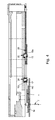
- This mechanism 1 essentially comprises a reset lever 2 and a lever 4 comprising two hammers 6 and 8. These hammers 6 and 8 each have an inclined striking face 6a and 8a by which they control the immobilization in a given angular position two cams 6b and 8b (see figure 2 ) corresponding to the zero of two time counters, one of which, denoted by the reference numeral 7, is visible at the figure 4 .
- the lever 4 with two hammers 6 and 8 has two pins 10 and 12 which are integral with the lever 4, for example by driving and riveting.
- the pin 10 is used in particular for the articulation pivoting between the lever 4 with two hammers 6, 8 and the reset lever 2.
- the reset lever 2 has an oblong hole 14 in which the pin 10 is slidable.
- a ring 16a is freely mounted on the pin 10 while two superposed rings 16b and 16c are mounted free on the pin 12.
- the ring 16c acts as a shim to compensate for the thickness of the lever. reset 2.
- the wedges 16b and 16c could be made in one piece.
- the shims 16a-16c can be metal parts Vietnamese or stones. In the latter case, they can be made in rubies.
- the lever 4 is in a position where the two hammers 6 and 8 immobilize the cams 6b and 8b in an angular position corresponding to the zero of the time counters. More specifically, the striking faces 6a and 8a of the hammers 6, 8 are supported on the respective shoulders 6c and 8c of the cams 6b and 8b.
- the lever 4 with two hammers 6, 8 is brought into the position illustrated in FIG. figure 2 by pressure of the user on a pusher (not shown) in the direction of the arrow F.
- This pressure is transmitted to the reset lever 2 by means of a rocker 18 against the restoring force d 20.
- the reset lever zero 2 rotates about its axis 22 in the direction of clockwise and causes the translation of the lever 4 to two hammers 6, 8 to the position shown in the figure 2 .
- the lever 4 with two hammers 6, 8 is guided in translation through its two pins 10, 12 adapted to move in two corresponding shaped holes 24 and 26 formed in a bridge or platen 28 of the movement (see figure 4 ).
- the rings 16a, 16b are free to rotating around the pins 10, 12, the frictional forces between said pins 10, 12 and the edges of the shaped holes 24, 26 are significantly reduced. This makes it possible to avoid that the reaction produced by the reset mechanism under the effect of its actuation is greater than the action exerted by the user to actuate this reset mechanism. If this condition was not fulfilled, the user action would become inoperative and the meters would come to a halt in an uncontrollable position.
Abstract
Description
La présente invention concerne un dispositif de remise à zéro simultanée de deux compteurs de temps. La présente invention concerne en particulier un dispositif de remise à zéro simultanée de deux compteurs de temps d'un mécanisme de chronographe dont les axes de pivotement sont solidaires de cames de remise à zéro respectives en forme de coeurs. Un tel dispositif comprend notamment un levier à deux marteaux venant frapper contre les coeurs pour les faire tourner et les ramener dans une position angulaire correspondant au zéro des compteurs.The present invention relates to a device for simultaneously resetting two time counters. The present invention relates in particular to a simultaneous resetting device of two time counters of a chronograph mechanism whose pivot axes are integral with respective resetting cams in the form of cores. Such a device comprises in particular a lever with two hammers striking against the cores to rotate them back to an angular position corresponding to the zero counters.
Pour effectuer la remise à zéro d'un compteur tel qu'un compteur de chronographe, on associe une came de remise à zéro en forme de coeur à l'axe du compteur. Une telle came est associée à un marteau qui présente une face de frappe telle que lorsqu'elle vient en appui sur les épaulements symétriques de la came, elle permet au marteau d'immobiliser le coeur dans une position angulaire correspondant au zéro du compteur. Si, en raison du fonctionnement du mécanisme de chronographe, la came en forme de coeur se trouve écartée de sa position angulaire correspondant au zéro du compteur et que le marteau vient la frapper, ladite came va tourner sous l'effet de la force du marteau et revenir dans sa position angulaire correspondant au zéro du compteur. Dans cette position, la face de frappe du marteau est en appui sur les deux épaulements de la came en forme de coeur et immobilise celle-ci.To reset a counter such as a chronograph counter, a heart-shaped reset cam is associated with the counter axis. Such a cam is associated with a hammer which has a striking face such that when it bears on the symmetrical shoulders of the cam, it allows the hammer to immobilize the heart in an angular position corresponding to the zero of the counter. If, because of the operation of the chronograph mechanism, the heart-shaped cam is spaced apart from its angular position corresponding to the zero of the counter and the hammer strikes it, said cam will rotate under the effect of the force of the hammer and return to its angular position corresponding to the zero of the counter. In this position, the striking face of the hammer is supported on the two shoulders of the heart-shaped cam and immobilizes it.
Pour effectuer la remise à zéro simultanée de deux compteurs, on utilise un levier à deux marteaux. Compte tenu des différentes tolérances, un tel dispositif ne permet pas en pratique d'obtenir un appui simultané des deux faces de frappe des marteaux sur les épaulements respectifs des deux coeurs en position de remise à zéro des deux compteurs, de sorte que la position zéro de l'un des deux compteurs n'est pas définie avec précision.To perform the simultaneous reset of two counters, a lever with two hammers is used. Given the different tolerances, such a device does not in practice make it possible to obtain simultaneous support of the two striking faces of the hammers on the respective shoulders of the two hearts in reset position of the two counters, so that the zero position of one of the two counters is not defined accurately.
Pour tenir compte de ces problèmes de tolérances, il a été prévu de laisser au levier à deux marteaux un léger degré de liberté en pivotement lorsqu'il arrive en bout de course. On comprendra en effet qu'en autorisant le levier à pivoter légèrement lorsque les faces de frappe de ses marteaux sont en appui sur les épaulements respectifs des deux coeurs, cela autorise le marteau à s'accommoder d'un léger décalage desdits coeurs et de ramener ceux-ci dans leur position angulaire correspondant au zéro des compteurs. Néanmoins, lorsque le levier pivote, cela génère des forces de frottement qui viennent s'ajouter aux forces résistantes opposées par les différents éléments du mécanisme de chronographe qui sont mis en action par pression de l'utilisateur sur le poussoir de commande. Ainsi, le bilan des forces peut être tel que l'action exercée par l'utilisateur sur le poussoir de commande devienne inférieure à la réaction des différents éléments mécaniques mis en marche sous l'effet de cette action. Il résulte d'une telle situation que l'action de l'utilisateur devient inopérante et que les compteurs s'immobilisent dans une position non contrôlable. Par conséquent, tout ce qui peut continuer à une diminution des forces de réaction opposées par le mécanisme de chronographe lorsqu'on commande celui-ci doit être examiné. A cet effet, il est du plus grand intérêt de chercher à réduire les forces de frottement qui s'opposent au déplacement du levier à deux marteaux.To take account of these problems of tolerance, it has been planned to leave the lever with two hammers a slight degree of freedom in pivoting when it reaches the end of the race. It will be understood that by allowing the lever to pivot slightly when the striking faces of his hammers are supported on the respective shoulders of the two hearts, it allows the hammer to accommodate a slight shift of said hearts and bring back these in their angular position corresponding to the zero of the counters. Nevertheless, when the lever pivots, it generates friction forces which are added to the resistant forces opposed by the various elements of the chronograph mechanism which are actuated by pressure of the user on the control pushbutton. Thus, the balance of forces may be such that the action exerted by the user on the control pusher becomes lower than the reaction of the various mechanical elements operated under the effect of this action. As a result of such a situation, the action of the user becomes inoperative and the meters come to rest in a non-controllable position. Therefore, anything that can continue to decrease reaction forces opposed by the chronograph mechanism when controlling it must be examined. For this purpose, it is of the greatest interest to seek to reduce the friction forces that oppose the movement of the lever with two hammers.
La présente invention a pour but de répondre à cet objectif ainsi qu'à d'autres encore en procurant un dispositif de remise à zéro de deux compteurs de temps dans lequel les forces de frottement sont réduites.The object of the present invention is to meet this and other objectives by providing a device for resetting two time counters in which the friction forces are reduced.
A cet effet, la présente invention concerne un dispositif pour pièce d'horlogerie de remise à zéro simultanée de deux compteurs de temps notamment pour un mécanisme de chronographe, chacun de ces deux compteurs de temps étant pivoté autour d'un axe solidaire d'une came, le dispositif de remise à zéro simultanée comprenant un levier à deux marteaux qui sont appliqués contre les cames respectives lors de la remise à zéro des deux compteurs de temps, au moins une goupille servant au guidage du levier à deux marteaux étant solidaire de ce levier et se déplaçant dans une ouverture de forme pratiquée dans un pont, caractérisé en ce qu'une bague est montée libre en rotation autour de la goupille et s'interpose entre ladite goupille et l'ouverture de forme dans laquelle celle-ci se déplace.For this purpose, the present invention relates to a timepiece device for simultaneous resetting of two time counters, in particular for a chronograph mechanism, each of these two time counters being rotated about an axis integral with a cam, the simultaneous resetting device comprising a lever with two hammers which are applied against the respective cams during the reset of the two time counters, at least a pin for guiding the lever with two hammers being integral with this lever and moving in a shaped opening made in a bridge, characterized in that a ring is mounted free to rotate around the pin and is interposed between said pin and the opening shape in which it moves.
Grâce à ces caractéristiques, la présente invention procure un dispositif de remise à zéro simultanée de deux compteurs de temps dans lequel le levier à deux marteaux chargé de ramener les compteurs à zéro en agissant sur les cames correspondantes oppose une moindre résistance au déplacement grâce au fait que, si sa goupille de guidage est forcée contre les rebords de l'ouverture de forme dans laquelle elle se déplace, ladite goupille va rouler via sa bague contre ces rebords et opposera donc une force de frottement moindre. Ceci s'avère particulièrement avantageux en phase de centrage, lorsque la goupille arrive au fond de l'ouverture de forme où elle présente un léger degré de liberté en pivotement pour permettre au levier à deux marteaux de s'accommoder d'un léger décalage des coeurs et de ramener ceux-ci dans leur position angulaire correspondant au zéro des compteurs. En effet, s'il n'y a pas égalité entre les moments définis comme étant le produit entre la force exercée par les marteaux sur les coeurs respectifs au niveau du point de contact entre un marteau et le coeur correspondant et la longueur de la normale à la ligne d'action de ladite force menée à partir de la goupille (bras de levier), il apparaît des contraintes qui s'exercent perpendiculairement aux rebords du trou de forme dans lequel se déplace la goupille. Par conséquent, la présence de la bague qui roule contre les rebords de l'ouverture de forme lorsque la goupille se déplace à l'intérieur de celle-ci permet de limiter les forces de frottement.Thanks to these features, the present invention provides a device for simultaneous resetting of two time counters in which the lever with two hammers responsible for bringing the counters to zero by acting on the corresponding cams opposes a lower resistance to displacement thanks to the fact that, if its guide pin is forced against the edges of the shaped opening in which it moves, said pin will roll via its ring against these flanges and therefore oppose a lower friction force. This is particularly advantageous in the centering phase, when the pin reaches the bottom of the opening shape where it has a slight degree of freedom in pivoting to allow the lever with two hammers to accommodate a slight shift of hearts and bring them back to their angular position corresponding to the zero of the counters. Indeed, if there is no equality between the moments defined as being the product between the force exerted by the hammers on the respective hearts at the point of contact between a hammer and the corresponding core and the length of the normal at the line of action of said force conducted from the pin (lever arm), there appear constraints that are exerted perpendicularly to the edges of the hole in which the pin moves. Therefore, the presence of the ring which rolls against the edges of the shape opening when the pin moves within it limits the friction forces.
Selon une caractéristique complémentaire de l'invention, le levier à deux marteaux est guidé par deux goupilles qui sont solidaires de ce levier et qui se déplacent chacune dans une ouverture de forme pratiquée dans le pont, l'une de ces goupilles permettant le couplage en pivotement entre ledit levier à deux marteaux et un levier de commande sur lequel l'utilisateur peut agir pour ramener les cames dans une position angulaire correspondant au zéro des compteurs.According to a complementary characteristic of the invention, the two-hammer lever is guided by two pins which are integral with this lever and which each move in an opening of shape made in the bridge, one of these pins allowing coupling in pivoting between said two-hammer lever and a control lever on which the user can act to return the cams to an angular position corresponding to the zero of the counters.
Selon une autre caractéristique de l'invention, la goupille par laquelle le levier à deux marteaux est articulé au levier de commande porte une bague, tandis que l'autre goupille porte deux bagues superposées dont celle de dessous joue le rôle de cale d'épaisseur pour compenser l'épaisseur du levier de commande.According to another characteristic of the invention, the pin by which the lever with two hammers is articulated to the control lever carries a ring, while the other pin carries two superposed rings, the one below plays the role of thick shim to compensate for the thickness of the control lever.
Selon encore une autre caractéristique de l'invention, la bague est une pièce métallique décolletée ou une pierre.According to yet another characteristic of the invention, the ring is a metal part décolletée or a stone.
Selon encore une autre caractéristique de l'invention, la pierre est un rubis.According to yet another characteristic of the invention, the stone is a ruby.
D'autres caractéristiques et avantages de la présente invention ressortiront plus clairement de la description détaillée qui suit d'un mode de réalisation du dispositif de remise à zéro instantanée selon l'invention, cet exemple étant donné à titre purement illustratif et non limitatif seulement en liaison avec le dessin annexé sur lequel :
- la
figure 1 est une vue en perspective du levier à deux marteaux et du levier de commande du dispositif de remise à zéro instantanée selon l'invention ; - la
figure 2 est une vue en plan du levier à deux marteaux et du levier de commande de lafigure 1 avec représentation des cames dont la position angulaire illustrée correspond au zéro des compteurs ; - la
figure 3 est une vue à plus grande échelle de la zone entourée d'un cercle sur lafigure 2 , et - la
figure 4 est une vue en coupe selon la ligne IV-IV du dispositif de remise à zéro instantanée selon l'invention représenté à lafigure 2 .
- the
figure 1 is a perspective view of the two-hammer lever and the control lever of the instantaneous reset device according to the invention; - the
figure 2 is a plan view of the two hammer lever and the control lever of thefigure 1 with representation of the cams whose illustrated angular position corresponds to the zero of the counters; - the
figure 3 is a larger-scale view of the area surrounded by a circle on thefigure 2 , and - the
figure 4 is a sectional view along line IV-IV of the instantaneous reset device according to the invention shown in FIG.figure 2 .
La présente invention procède de l'idée générale inventive qui consiste à réduire les forces de frottement qui s'exercent sur le levier à double marteaux d'un mécanisme de remise à zéro instantanée d'un dispositif d'affichage à deux compteurs de temps dans le double but de limiter les forces de réaction exercées par le mécanisme sous l'effet de son actionnement à une valeur inférieure à la valeur de l'action exercée par l'utilisateur pour mettre ce mécanisme en marche, et de s'assurer que la force exercée par les faces de frappe des marteaux sur les coeurs est bien perpendiculaire aux épaulements des cames ou, tout du moins, s'inscrit dans un secteur angulaire limité garantissant l'immobilisation des cames dans une position angulaire déterminée correspondant au zéro des compteurs.The present invention proceeds from the general inventive idea of reducing the frictional forces on the double-hammer lever of an instantaneous reset mechanism of a dual-time display in the dual purpose of limiting the reaction forces exerted by the mechanism under the effect of its actuation to a value lower than the value of the action exerted by the user to put this mechanism into operation, and to ensure that the The force exerted by the striking faces of the hammers on the cores is perpendicular to the shoulders of the cams or, at least, fits in a limited angular sector ensuring the immobilization of the cams in a specific angular position corresponding to the zero of the counters.
On comprendra que la présente invention se rapporte essentiellement à une nouvelle conception d'un mécanisme de remise à zéro instantanée comprenant un levier à deux marteaux et qu'un tel mécanisme peut tout aussi bien être utilisé dans un mécanisme de chronographe à deux compteurs de temps que dans n'importe quel autre mécanisme compteur de temps comprenant deux dispositifs d'affichage (minute et seconde par exemple) devant être remis à zéro simultanément à l'aide d'un levier de commande ou de remise à zéro.It will be understood that the present invention essentially relates to a new design of an instantaneous reset mechanism comprising a two-hammer lever and that such a mechanism can equally well be used in a chronograph mechanism with two time counters. in any other time counter mechanism comprising two display devices (minute and second for example) to be reset simultaneously using a control lever or reset.
On comprendra également que, bien que décrite en liaison avec un levier à deux marteaux, la présente invention peut tout aussi bien s'appliquer à un mécanisme comprenant un levier à un marteau ou à trois marteaux.It will also be understood that, although described in connection with a two-hammer lever, the present invention can equally well be applied to a mechanism comprising a lever with a hammer or with three hammers.
Désigné dans son ensemble par la référence numérique générale 1, le mécanisme de remise à zéro instantanée selon l'invention est représenté partiellement et en perspective à la
Comme on peut le voir à l'examen de la
Dans la situation représentée à la
Le levier 4 à deux marteaux 6, 8 est amené dans la position illustrée à la
On remarque que le levier 4 à deux marteaux 6, 8 est guidé en translation par le biais de ses deux goupilles 10, 12 aptes à se déplacer dans deux trous de forme correspondants 24 et 26 pratiqués dans un pont ou platine 28 du mouvement (voir
Le fait de prévoir des bagues 16a, 16b mobiles en rotation sur les goupilles 10, 12 qui servent au guidage en translation du levier 4 à double marteaux 6, 8 présente également un grand intérêt lorsque la goupille 12 arrive au fond de son trou de forme 26. En effet, comme il peut être vu à la
Il va de soi que la présente invention n'est pas limitée aux modes de réalisation qui viennent d'être décrits et que diverses modifications et variantes simples peuvent être envisagées par l'homme du métier sans sortir du cadre de l'invention tel que défini par les revendications annexées.It goes without saying that the present invention is not limited to the embodiments which have just been described and that various modifications and simple variants can be envisaged by those skilled in the art without departing from the scope of the invention as defined by the appended claims.
Claims (5)
Priority Applications (5)
| Application Number | Priority Date | Filing Date | Title |
|---|---|---|---|
| EP07117757.0A EP2045672B1 (en) | 2007-10-02 | 2007-10-02 | Device for resetting two time counters |
| US12/238,678 US7871197B2 (en) | 2007-10-02 | 2008-09-26 | Zero reset device for two time counters |
| JP2008256195A JP5346195B2 (en) | 2007-10-02 | 2008-10-01 | Zero reset device for two time counters |
| CN2008101659824A CN101404070B (en) | 2007-10-02 | 2008-10-06 | Device for resetting two time counters |
| HK09108522.1A HK1130925A1 (en) | 2007-10-02 | 2009-09-17 | Zero reset device for two time counters |
Applications Claiming Priority (1)
| Application Number | Priority Date | Filing Date | Title |
|---|---|---|---|
| EP07117757.0A EP2045672B1 (en) | 2007-10-02 | 2007-10-02 | Device for resetting two time counters |
Publications (2)
| Publication Number | Publication Date |
|---|---|
| EP2045672A1 true EP2045672A1 (en) | 2009-04-08 |
| EP2045672B1 EP2045672B1 (en) | 2014-02-26 |
Family
ID=39495654
Family Applications (1)
| Application Number | Title | Priority Date | Filing Date |
|---|---|---|---|
| EP07117757.0A Active EP2045672B1 (en) | 2007-10-02 | 2007-10-02 | Device for resetting two time counters |
Country Status (5)
| Country | Link |
|---|---|
| US (1) | US7871197B2 (en) |
| EP (1) | EP2045672B1 (en) |
| JP (1) | JP5346195B2 (en) |
| CN (1) | CN101404070B (en) |
| HK (1) | HK1130925A1 (en) |
Families Citing this family (9)
| Publication number | Priority date | Publication date | Assignee | Title |
|---|---|---|---|---|
| JP2010261815A (en) * | 2009-05-07 | 2010-11-18 | Seiko Instruments Inc | Chronograph mechanism and chronograph timepiece including the same |
| JP5536623B2 (en) * | 2010-02-03 | 2014-07-02 | セイコーインスツル株式会社 | Chronograph clock |
| EP2362276B1 (en) * | 2010-02-25 | 2012-10-31 | Montres Breguet SA | Programmable and reprogrammable mechanical memory wheel for a timepiece |
| EP2362277B1 (en) * | 2010-02-25 | 2012-10-31 | Montres Breguet SA | On-demand time zone displayed on the main hand of a timepiece |
| EP2503407B1 (en) * | 2011-03-23 | 2017-06-28 | Montres Breguet SA | Timepiece movement comprising an instant actuator controlled by the movement |
| US9146541B2 (en) * | 2011-06-29 | 2015-09-29 | Rolex S.A. | Device for resetting to a predetermined position an indicator member indicative of a parameter connected with time |
| CH708999A1 (en) * | 2013-12-16 | 2015-06-30 | Société Anonyme De La Manufacture D Horlogerie Audemars Piguet & Cie | Device reset with independent hammers. |
| DE202017107668U1 (en) * | 2017-12-18 | 2018-01-19 | Uwe Heinz | Zeroing device for minute hand of a chronograph and chronograph |
| US20220276609A1 (en) * | 2019-04-15 | 2022-09-01 | Rolex Sa | Cam-type timepiece component |
Citations (3)
| Publication number | Priority date | Publication date | Assignee | Title |
|---|---|---|---|---|
| CH346170A (en) * | 1958-04-25 | 1960-04-30 | Roamer Watch Co Sa | Calendar timepiece |
| CH560766A5 (en) | 1972-04-18 | 1975-04-15 | Siemens Ag | |
| US3927519A (en) | 1973-12-07 | 1975-12-23 | Suisse Horlogerie | Timepiece movement with a timer mechanism |
Family Cites Families (7)
| Publication number | Priority date | Publication date | Assignee | Title |
|---|---|---|---|---|
| GB1405101A (en) * | 1971-08-20 | 1975-09-03 | Smiths Industries Ltd | Reset mechanisms for use in stopwatches |
| CH500273A4 (en) * | 1973-04-06 | 1975-05-30 | ||
| CH670187GA3 (en) * | 1987-05-12 | 1989-05-31 | ||
| CH690524A5 (en) * | 1995-10-31 | 2000-09-29 | Rolex Montres | Piece chronograph mechanism watchmaking. |
| JP3265232B2 (en) * | 1997-07-07 | 2002-03-11 | セイコーインスツルメンツ株式会社 | Chronograph clock |
| DE60139155D1 (en) * | 2001-03-21 | 2009-08-13 | Glashuetter Uhrenbetrieb Gmbh | CHRONOGRAPH WITH TWO DIRECTIONS |
| EP1746471B1 (en) * | 2005-07-20 | 2019-09-18 | Breitling AG | Return-to-zero device for two time counters |
-
2007
- 2007-10-02 EP EP07117757.0A patent/EP2045672B1/en active Active
-
2008
- 2008-09-26 US US12/238,678 patent/US7871197B2/en active Active
- 2008-10-01 JP JP2008256195A patent/JP5346195B2/en active Active
- 2008-10-06 CN CN2008101659824A patent/CN101404070B/en active Active
-
2009
- 2009-09-17 HK HK09108522.1A patent/HK1130925A1/en unknown
Patent Citations (3)
| Publication number | Priority date | Publication date | Assignee | Title |
|---|---|---|---|---|
| CH346170A (en) * | 1958-04-25 | 1960-04-30 | Roamer Watch Co Sa | Calendar timepiece |
| CH560766A5 (en) | 1972-04-18 | 1975-04-15 | Siemens Ag | |
| US3927519A (en) | 1973-12-07 | 1975-12-23 | Suisse Horlogerie | Timepiece movement with a timer mechanism |
Also Published As
| Publication number | Publication date |
|---|---|
| CN101404070A (en) | 2009-04-08 |
| CN101404070B (en) | 2013-04-17 |
| JP5346195B2 (en) | 2013-11-20 |
| US7871197B2 (en) | 2011-01-18 |
| EP2045672B1 (en) | 2014-02-26 |
| US20090086583A1 (en) | 2009-04-02 |
| HK1130925A1 (en) | 2010-01-08 |
| JP2009085957A (en) | 2009-04-23 |
Similar Documents
| Publication | Publication Date | Title |
|---|---|---|
| EP2045672B1 (en) | Device for resetting two time counters | |
| EP1960847B1 (en) | Time piece chronograph clockwork movement | |
| EP2365407B1 (en) | Device for actuating the winding-up and the time setting of a clockwork | |
| EP2503412B1 (en) | Uhrwerk, das eine Vorrichtung mit fortschreitender Zeitgleichung umfasst | |
| EP1617305B1 (en) | Stopping device during hand-setting of a watch provided with a tourbillon | |
| EP2503407B1 (en) | Timepiece movement comprising an instant actuator controlled by the movement | |
| EP2073079A2 (en) | Chronograph mechanism, timepiece movement and timepiece comprising such a mechanism | |
| CH706021B1 (en) | watch movement type and chronograph timepiece provided with such a movement. | |
| EP1406132B1 (en) | Coupling mechanism for a chronographe | |
| EP1960843B1 (en) | Timepiece movement | |
| EP1960846B1 (en) | Clockwork movement | |
| EP1978424B1 (en) | Chronograph | |
| EP3502793B1 (en) | Surprise mechanism | |
| EP2241945B1 (en) | Chronograph mechanism and timepiece equipped with such mechanism | |
| EP2615505A1 (en) | Mechanism for indicating on request information for a timepiece movement | |
| EP2339414B1 (en) | Chronograph with single push button | |
| CH702179B1 (en) | Still second system for a timepiece. | |
| CH527462A (en) | Chronograph watch | |
| WO2014016499A1 (en) | Saxophone with improved octave key mechanism actuation | |
| CH702429A2 (en) | Mono-button chronograph for timepiece, has inclined surface that is arranged such that jumper pivots shuttle from intermediate instable angular position to stable angular position when button is released | |
| CH710892B1 (en) | Chronograph mechanism for watch movement. | |
| CH720106A2 (en) | Split-seconds chronograph mechanism | |
| CH718458A1 (en) | Actuation mechanism for a watch movement, in particular a chronograph mechanism comprising such an actuation mechanism. | |
| CH714505A2 (en) | Surprise mechanism for timepiece with striking. | |
| CH711924B1 (en) | Split-seconds chronograph mechanism with isolator. |
Legal Events
| Date | Code | Title | Description |
|---|---|---|---|
| PUAI | Public reference made under article 153(3) epc to a published international application that has entered the european phase |
Free format text: ORIGINAL CODE: 0009012 |
|
| AK | Designated contracting states |
Kind code of ref document: A1 Designated state(s): AT BE BG CH CY CZ DE DK EE ES FI FR GB GR HU IE IS IT LI LT LU LV MC MT NL PL PT RO SE SI SK TR |
|
| AX | Request for extension of the european patent |
Extension state: AL BA HR MK RS |
|
| 17P | Request for examination filed |
Effective date: 20091008 |
|
| 17Q | First examination report despatched |
Effective date: 20091106 |
|
| AKX | Designation fees paid |
Designated state(s): AT BE BG CH CY CZ DE DK EE ES FI FR GB GR HU IE IS IT LI LT LU LV MC MT NL PL PT RO SE SI SK TR |
|
| GRAP | Despatch of communication of intention to grant a patent |
Free format text: ORIGINAL CODE: EPIDOSNIGR1 |
|
| INTG | Intention to grant announced |
Effective date: 20131017 |
|
| GRAS | Grant fee paid |
Free format text: ORIGINAL CODE: EPIDOSNIGR3 |
|
| GRAA | (expected) grant |
Free format text: ORIGINAL CODE: 0009210 |
|
| AK | Designated contracting states |
Kind code of ref document: B1 Designated state(s): AT BE BG CH CY CZ DE DK EE ES FI FR GB GR HU IE IS IT LI LT LU LV MC MT NL PL PT RO SE SI SK TR |
|
| REG | Reference to a national code |
Ref country code: GB Ref legal event code: FG4D Free format text: NOT ENGLISH |
|
| REG | Reference to a national code |
Ref country code: CH Ref legal event code: EP |
|
| REG | Reference to a national code |
Ref country code: AT Ref legal event code: REF Ref document number: 653936 Country of ref document: AT Kind code of ref document: T Effective date: 20140315 |
|
| REG | Reference to a national code |
Ref country code: CH Ref legal event code: NV Representative=s name: ICB INGENIEURS CONSEILS EN BREVETS SA, CH |
|
| REG | Reference to a national code |
Ref country code: IE Ref legal event code: FG4D Free format text: LANGUAGE OF EP DOCUMENT: FRENCH |
|
| REG | Reference to a national code |
Ref country code: DE Ref legal event code: R096 Ref document number: 602007035183 Country of ref document: DE Effective date: 20140417 |
|
| REG | Reference to a national code |
Ref country code: NL Ref legal event code: VDEP Effective date: 20140226 |
|
| REG | Reference to a national code |
Ref country code: AT Ref legal event code: MK05 Ref document number: 653936 Country of ref document: AT Kind code of ref document: T Effective date: 20140226 |
|
| REG | Reference to a national code |
Ref country code: LT Ref legal event code: MG4D |
|
| PG25 | Lapsed in a contracting state [announced via postgrant information from national office to epo] |
Ref country code: IS Free format text: LAPSE BECAUSE OF FAILURE TO SUBMIT A TRANSLATION OF THE DESCRIPTION OR TO PAY THE FEE WITHIN THE PRESCRIBED TIME-LIMIT Effective date: 20140626 Ref country code: LT Free format text: LAPSE BECAUSE OF FAILURE TO SUBMIT A TRANSLATION OF THE DESCRIPTION OR TO PAY THE FEE WITHIN THE PRESCRIBED TIME-LIMIT Effective date: 20140226 |
|
| PG25 | Lapsed in a contracting state [announced via postgrant information from national office to epo] |
Ref country code: AT Free format text: LAPSE BECAUSE OF FAILURE TO SUBMIT A TRANSLATION OF THE DESCRIPTION OR TO PAY THE FEE WITHIN THE PRESCRIBED TIME-LIMIT Effective date: 20140226 Ref country code: CY Free format text: LAPSE BECAUSE OF FAILURE TO SUBMIT A TRANSLATION OF THE DESCRIPTION OR TO PAY THE FEE WITHIN THE PRESCRIBED TIME-LIMIT Effective date: 20140226 Ref country code: PT Free format text: LAPSE BECAUSE OF FAILURE TO SUBMIT A TRANSLATION OF THE DESCRIPTION OR TO PAY THE FEE WITHIN THE PRESCRIBED TIME-LIMIT Effective date: 20140626 Ref country code: FI Free format text: LAPSE BECAUSE OF FAILURE TO SUBMIT A TRANSLATION OF THE DESCRIPTION OR TO PAY THE FEE WITHIN THE PRESCRIBED TIME-LIMIT Effective date: 20140226 Ref country code: NL Free format text: LAPSE BECAUSE OF FAILURE TO SUBMIT A TRANSLATION OF THE DESCRIPTION OR TO PAY THE FEE WITHIN THE PRESCRIBED TIME-LIMIT Effective date: 20140226 Ref country code: SE Free format text: LAPSE BECAUSE OF FAILURE TO SUBMIT A TRANSLATION OF THE DESCRIPTION OR TO PAY THE FEE WITHIN THE PRESCRIBED TIME-LIMIT Effective date: 20140226 |
|
| PG25 | Lapsed in a contracting state [announced via postgrant information from national office to epo] |
Ref country code: LV Free format text: LAPSE BECAUSE OF FAILURE TO SUBMIT A TRANSLATION OF THE DESCRIPTION OR TO PAY THE FEE WITHIN THE PRESCRIBED TIME-LIMIT Effective date: 20140226 |
|
| PG25 | Lapsed in a contracting state [announced via postgrant information from national office to epo] |
Ref country code: CZ Free format text: LAPSE BECAUSE OF FAILURE TO SUBMIT A TRANSLATION OF THE DESCRIPTION OR TO PAY THE FEE WITHIN THE PRESCRIBED TIME-LIMIT Effective date: 20140226 Ref country code: DK Free format text: LAPSE BECAUSE OF FAILURE TO SUBMIT A TRANSLATION OF THE DESCRIPTION OR TO PAY THE FEE WITHIN THE PRESCRIBED TIME-LIMIT Effective date: 20140226 Ref country code: EE Free format text: LAPSE BECAUSE OF FAILURE TO SUBMIT A TRANSLATION OF THE DESCRIPTION OR TO PAY THE FEE WITHIN THE PRESCRIBED TIME-LIMIT Effective date: 20140226 Ref country code: RO Free format text: LAPSE BECAUSE OF FAILURE TO SUBMIT A TRANSLATION OF THE DESCRIPTION OR TO PAY THE FEE WITHIN THE PRESCRIBED TIME-LIMIT Effective date: 20140226 |
|
| REG | Reference to a national code |
Ref country code: DE Ref legal event code: R097 Ref document number: 602007035183 Country of ref document: DE |
|
| PG25 | Lapsed in a contracting state [announced via postgrant information from national office to epo] |
Ref country code: ES Free format text: LAPSE BECAUSE OF FAILURE TO SUBMIT A TRANSLATION OF THE DESCRIPTION OR TO PAY THE FEE WITHIN THE PRESCRIBED TIME-LIMIT Effective date: 20140226 Ref country code: PL Free format text: LAPSE BECAUSE OF FAILURE TO SUBMIT A TRANSLATION OF THE DESCRIPTION OR TO PAY THE FEE WITHIN THE PRESCRIBED TIME-LIMIT Effective date: 20140226 Ref country code: SK Free format text: LAPSE BECAUSE OF FAILURE TO SUBMIT A TRANSLATION OF THE DESCRIPTION OR TO PAY THE FEE WITHIN THE PRESCRIBED TIME-LIMIT Effective date: 20140226 |
|
| PLBE | No opposition filed within time limit |
Free format text: ORIGINAL CODE: 0009261 |
|
| STAA | Information on the status of an ep patent application or granted ep patent |
Free format text: STATUS: NO OPPOSITION FILED WITHIN TIME LIMIT |
|
| 26N | No opposition filed |
Effective date: 20141127 |
|
| REG | Reference to a national code |
Ref country code: DE Ref legal event code: R097 Ref document number: 602007035183 Country of ref document: DE Effective date: 20141127 |
|
| PG25 | Lapsed in a contracting state [announced via postgrant information from national office to epo] |
Ref country code: LU Free format text: LAPSE BECAUSE OF FAILURE TO SUBMIT A TRANSLATION OF THE DESCRIPTION OR TO PAY THE FEE WITHIN THE PRESCRIBED TIME-LIMIT Effective date: 20141002 Ref country code: MC Free format text: LAPSE BECAUSE OF FAILURE TO SUBMIT A TRANSLATION OF THE DESCRIPTION OR TO PAY THE FEE WITHIN THE PRESCRIBED TIME-LIMIT Effective date: 20140226 Ref country code: SI Free format text: LAPSE BECAUSE OF FAILURE TO SUBMIT A TRANSLATION OF THE DESCRIPTION OR TO PAY THE FEE WITHIN THE PRESCRIBED TIME-LIMIT Effective date: 20140226 |
|
| PG25 | Lapsed in a contracting state [announced via postgrant information from national office to epo] |
Ref country code: BE Free format text: LAPSE BECAUSE OF NON-PAYMENT OF DUE FEES Effective date: 20141031 |
|
| REG | Reference to a national code |
Ref country code: IE Ref legal event code: MM4A |
|
| PG25 | Lapsed in a contracting state [announced via postgrant information from national office to epo] |
Ref country code: IE Free format text: LAPSE BECAUSE OF NON-PAYMENT OF DUE FEES Effective date: 20141002 |
|
| PG25 | Lapsed in a contracting state [announced via postgrant information from national office to epo] |
Ref country code: BG Free format text: LAPSE BECAUSE OF FAILURE TO SUBMIT A TRANSLATION OF THE DESCRIPTION OR TO PAY THE FEE WITHIN THE PRESCRIBED TIME-LIMIT Effective date: 20140226 |
|
| PG25 | Lapsed in a contracting state [announced via postgrant information from national office to epo] |
Ref country code: GR Free format text: LAPSE BECAUSE OF FAILURE TO SUBMIT A TRANSLATION OF THE DESCRIPTION OR TO PAY THE FEE WITHIN THE PRESCRIBED TIME-LIMIT Effective date: 20140527 |
|
| PG25 | Lapsed in a contracting state [announced via postgrant information from national office to epo] |
Ref country code: HU Free format text: LAPSE BECAUSE OF FAILURE TO SUBMIT A TRANSLATION OF THE DESCRIPTION OR TO PAY THE FEE WITHIN THE PRESCRIBED TIME-LIMIT; INVALID AB INITIO Effective date: 20071002 Ref country code: TR Free format text: LAPSE BECAUSE OF FAILURE TO SUBMIT A TRANSLATION OF THE DESCRIPTION OR TO PAY THE FEE WITHIN THE PRESCRIBED TIME-LIMIT Effective date: 20140226 Ref country code: MT Free format text: LAPSE BECAUSE OF FAILURE TO SUBMIT A TRANSLATION OF THE DESCRIPTION OR TO PAY THE FEE WITHIN THE PRESCRIBED TIME-LIMIT Effective date: 20140226 |
|
| REG | Reference to a national code |
Ref country code: FR Ref legal event code: PLFP Year of fee payment: 10 |
|
| REG | Reference to a national code |
Ref country code: FR Ref legal event code: PLFP Year of fee payment: 11 |
|
| PGFP | Annual fee paid to national office [announced via postgrant information from national office to epo] |
Ref country code: GB Payment date: 20170925 Year of fee payment: 11 |
|
| REG | Reference to a national code |
Ref country code: FR Ref legal event code: PLFP Year of fee payment: 12 |
|
| GBPC | Gb: european patent ceased through non-payment of renewal fee |
Effective date: 20181002 |
|
| PG25 | Lapsed in a contracting state [announced via postgrant information from national office to epo] |
Ref country code: IT Free format text: LAPSE BECAUSE OF NON-PAYMENT OF DUE FEES Effective date: 20181002 Ref country code: GB Free format text: LAPSE BECAUSE OF NON-PAYMENT OF DUE FEES Effective date: 20181002 |
|
| P01 | Opt-out of the competence of the unified patent court (upc) registered |
Effective date: 20230701 |
|
| PGFP | Annual fee paid to national office [announced via postgrant information from national office to epo] |
Ref country code: FR Payment date: 20230920 Year of fee payment: 17 |
|
| PGFP | Annual fee paid to national office [announced via postgrant information from national office to epo] |
Ref country code: DE Payment date: 20230920 Year of fee payment: 17 Ref country code: CH Payment date: 20231102 Year of fee payment: 17 |