EP2045626B1 - Vorrichtung für SPECT-Untersuchungen - Google Patents
Vorrichtung für SPECT-Untersuchungen Download PDFInfo
- Publication number
- EP2045626B1 EP2045626B1 EP08105918.0A EP08105918A EP2045626B1 EP 2045626 B1 EP2045626 B1 EP 2045626B1 EP 08105918 A EP08105918 A EP 08105918A EP 2045626 B1 EP2045626 B1 EP 2045626B1
- Authority
- EP
- European Patent Office
- Prior art keywords
- pinhole collimator
- detector
- pinhole
- holes
- collimator
- Prior art date
- Legal status (The legal status is an assumption and is not a legal conclusion. Google has not performed a legal analysis and makes no representation as to the accuracy of the status listed.)
- Expired - Lifetime
Links
Images
Classifications
-
- G—PHYSICS
- G01—MEASURING; TESTING
- G01T—MEASUREMENT OF NUCLEAR OR X-RADIATION
- G01T1/00—Measuring X-radiation, gamma radiation, corpuscular radiation, or cosmic radiation
- G01T1/16—Measuring radiation intensity
- G01T1/161—Applications in the field of nuclear medicine, e.g. in vivo counting
- G01T1/164—Scintigraphy
- G01T1/1641—Static instruments for imaging the distribution of radioactivity in one or two dimensions using one or several scintillating elements; Radio-isotope cameras
- G01T1/1648—Ancillary equipment for scintillation cameras, e.g. reference markers, devices for removing motion artifacts, calibration devices
Definitions
- the invention relates to a device and a method for tomography, in particular for single gamma quantum tomography (SPECT).
- SPECT single gamma quantum tomography
- Single photon tomography refers to a method and associated apparatus for three-dimensional imaging of radiopharmaceuticals that have been placed in an object.
- an object humans or animals can be provided.
- the radiopharmaceuticals brought into the object send gamma quanta.
- the gamma quanta are detected and evaluated by the device.
- the position, ie the spatial distribution of the radiopharmaceuticals in the object is obtained.
- the location of the radiopharmaceuticals in turn allows conclusions about the object, such as a distribution of tissue in the object.
- a known device for performing a single gamma quantum tomography comprises a gamma camera and an upstream collimator.
- the collimator is generally a lead plate having a plurality of channels perpendicularly passing through the plate. The provision of the channels ensures that on the one hand only vertically incident gamma quanta are detected and on the other hand a spatially resolving measurement is possible.
- the camera and the collimator are moved around the object. This gives you a variety of location information. These are so-called projection photographs. From the obtained location information around the object, the location of the radiopharmaceuticals in the object can then be determined.
- the camera In order to be able to hide scattered radiation caused by the gamma quanta, energy information is generally still required.
- the camera is therefore usually designed with her immediately the energy of the incident gamma quanta can be determined.
- Stray radiation basically has a lower energy compared to the actual measuring radiation.
- scattered radiation can be masked out by ignoring low-energy gamma quanta.
- Setting an upper limit on the energy of the gamma quanta may also be of interest in order to hide background radiation.
- Single gamma quantum tomography (SPECT) and positron emission tomography (PET) are tools for the quantitative representation of spatial radiotracer distributions in vivo.
- SPECT single gamma quantum tomography
- PET positron emission tomography
- these techniques can be used in pharmacological and preclinical research to develop and evaluate novel tracer compounds deploy. While various systems for the examination of small laboratory animals are available today in PET, there have been no or only insufficient developments in the field of SPECT, and this despite the fact that TC-99m and I-123-labeled radiopharmaceuticals are unequal in nuclear medicine are more important than PET nuclides.
- a pinhole collimator is used in single-gamma quantum tomography.
- a pinhole collimator is characterized by a single hole (pinhole) through which the gamma quanta pass. If the object is located closer to the pinhole collimator than the surface of a gamma camera or a detector, this finally results in an increased spatial resolution.
- the gamma quanta do not pass vertically through the pinhole collimator. Instead, they taper in and out again. Since the cone lying behind the pinhole collimator is larger than the cone in front of the pinhole collimator, the result is an improvement in the spatial resolution compared to the prior art mentioned in the introduction.
- a small passage opening or a small hole is to be provided, through which the gamma quanta pass, in order to obtain a good spatial resolution.
- Sensitivity is defined as the ratio of the measured count rate to the activity present in the object.
- the object of the invention is to provide a device together with the associated method of the type mentioned, can be measured with the high-resolution and highly sensitive.
- the claimed device comprises a multi-pinhole collimator together with a detector for detecting the gamma quanta, which by the Pass multi-pinhole collimator.
- the collimator thus has a plurality of passage openings.
- the detector is such that it is also able to determine the energy of the incident gamma quanta.
- the collimator Since the collimator has multiple holes, the sensitivity of the device increases accordingly.
- the use of a pinhole collimator has the advantage of high spatial resolution compared to the use of such collimators, with which only perpendicularly incident rays are detected. Thus, a device with good spatial resolution and good sensitivity is available.
- the object is closer to the multi-pinhole collimator than the camera or detector surface to achieve good spatial resolution.
- the support for the object is therefore closer to the multi-pinhole collimator than the camera or the detector.
- the distances of the individual passages or holes in the multi-pinhole collimator are preferably selected so that the cones that impinge on the camera, at most partially overlap. To achieve a good spatial resolution and good sensitivity, it is advantageous to allow overlapping areas. In one embodiment of the invention, these amount to no more than 30%, preferably up to 70%, of the total area of a cone formed by the gamma quanta passing through a hole of the multi-pinhole collimator.
- the center of the hole lies on the center vertical of the detector. Furthermore, the hole axis, ie the axis of symmetry of the collimator hole, is perpendicular to the detector.
- a reconstruction method is then used in which it is assumed that the gamma quantum falling from the center of the object onto the camera forms a right angle with the camera surface.
- the base of the cone, which is displayed on the camera, is then basically circular.
- a reconstruction method which takes into account the deviating conditions. If a gamma quantum originating from the center of the object is no longer perpendicular to the surface of the camera or the detector, no circular cone (idealized state) is imaged on the camera surface. Instead, the cone basically forms in the form of an ellipse on the camera. According to the invention, this problem is solved by using an iterative reconstruction method.
- the starting point of the iterative reconstruction method is an assumed distribution in the object, generally a spatial distribution. It is then calculated which measurement result would achieve the assumed distribution. The calculated result is compared with the actually measured.
- the iterative reconstruction method is finished, in particular, when the calculated result agrees with the measured one with a predetermined accuracy.
- the iteration method thus comprises a so-called forward projection, ie the calculation of the result of an assumed distribution.
- the iterative method further has the advantage that overlapping areas of the cones imaged on the camera or detector surface can be calculated and compared with the actual result. It is therefore for this reason preferable to other reconstruction methods. It is thus possible to allow overlapping areas and thus achieve good spatial resolution.
- the multi-pinhole collimator comprises a plate made of tungsten and iridium is. These materials have a better attenuation coefficient than gamma quanta compared to lead. Iridium is among the materials best suited to weaken gamma quanta. Iridium is very expensive. Therefore, for cost reasons, tungsten is used at the places where the requirements for the weakening behavior are less great. Iridium is used to make the parts of the plate where the requirements for attenuation of gamma quanta are particularly high. These are in particular the areas of the plate which adjoin the holes.
- a hole in the plate advantageously opens funnel-shaped into the plate from both sides.
- the funnel walls are preferably made of iridium.
- the plate is then typically 3 to 10 mm thick.
- Gamma quanta emanating from the interior of the object are usually weakened depending on the tissue.
- a homogeneous attenuation coefficient corresponding to the attenuation coefficient of water is assumed.
- the weakening depends on the contours of the object.
- the outer contour of the object is determined in the context of the evaluation and the attenuation is calculated as a function of the outline. In this way, further improved results are obtained.
- the Compton scattered radiation is measured for example in a so-called Compton window.
- the Compton scattered radiation is taken into account and from this the outline of the object is determined.
- a gamma quantum hits a camera or the detector
- the location of the impact is measured with a camera or detector-specific inaccuracy.
- the method is taken into account in the forward projection, which is the basis of the iterative reconstruction method, the imaging property, so the camera or detector typical inaccuracy in the evaluation. Again, the consideration of the measurement inaccuracy by an iterative method of the aforementioned type succeeds reliable.
- the sensitivity decreases. In one embodiment of the reconstruction method, this decreasing sensitivity is taken into account in the forward projection.
- the imaging behavior of the camera or detector also depends on the distance that exists between the radiating source and the multi-pinhole collimator. This imaging behavior, which changes depending on the distance, is also considered iteratively in one embodiment of the method.
- the calculation of the object contour in one embodiment is performed in the "zeroth" iteration.
- a quality degrading property of Compton scattering is exploited for this purpose: the directionally wrongly detected gamma quanta.
- An aperture file typically has the following structure: 7 45 18435 66503 1.5 60 22278 21:53 27.9 45 -18,435 55858 1.5 60 -22,278 26164 27.9 45 36871 13306 1.5 60 39.33 -6.8974 27.9 45 0 2.6613 1.5 60 0 -1.3859 27.9 45 -36,871 -7.9839 1.5 60 -39.33 4.1513 27.9 45 18435 -50,535 1.5 60 22278 -28,355 27.9 45 -18,435 -61,181 1.5 60 -22,279 -23,889 27.9
- the first entry is the number of holes.
- Each following line describes a pinhole.
- the meaning of the entries is the following: column importance 1 x-coordinate of the pinholing point, ie distance of the pinhole from the axis of rotation in mm 2 y-coord. of the pinhole, ie transverse deflection of the PH 3 z coord.
- Pinholes ie axial deflection of the PH 4 Inner diameter of the double funnel-shaped pinhole 5 Opening angle of Pinholes in degrees 6 Lateral, ie transversal inclination angle of the pinhole axis 7 Axial inclination angle of the PH axis 8th Attenuation coefficient of the aperture material in 1 / cm
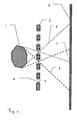
- An object 1 is closer to a multi-pinhole collimator 3 than the detector surface 2.
- the multi-pinhole collimator 3 has holes 4 funnel-shaped opening into the collimator 3 from both sides, thus allowing a passage of obliquely incident gamma quanta through the To allow holes.
- the tips 5 of the multi-pinhole collimator 3 are made of iridium.
- the remaining areas of the multi-pinhole collimator 3 are made of tungsten.
- Gamma quanta 6 pass from the object 1 through the holes 4 onto the detector surface 2.
- the object 1 is reproduced in an enlarged manner on the detector surface 2. Between the individual cones, which are formed by the gamma quanta, there are overlapping areas 7.
- the holes 4 with each other evenly spaced may also be irregular.
Landscapes
- Physics & Mathematics (AREA)
- Health & Medical Sciences (AREA)
- Life Sciences & Earth Sciences (AREA)
- Molecular Biology (AREA)
- General Health & Medical Sciences (AREA)
- Medical Informatics (AREA)
- Nuclear Medicine, Radiotherapy & Molecular Imaging (AREA)
- Optics & Photonics (AREA)
- Engineering & Computer Science (AREA)
- General Physics & Mathematics (AREA)
- High Energy & Nuclear Physics (AREA)
- Biomedical Technology (AREA)
- Spectroscopy & Molecular Physics (AREA)
- Nuclear Medicine (AREA)
- Measurement Of Radiation (AREA)
- Crystals, And After-Treatments Of Crystals (AREA)
- Investigating Or Analysing Materials By Optical Means (AREA)
- Electrotherapy Devices (AREA)
- Luminescent Compositions (AREA)
Description
- Die Erfindung betrifft eine Vorrichtung sowie ein Verfahren zur Tomographie, insbesondere zur Einzelgammaquanten-Tomographie (SPECT).
- Die Einzelphotonen-Tomographie bezieht sich auf ein Verfahren nebst zugehörigen Vorrichtungen zur dreidimensionalen Darstellungen von Radiopharmaka, die in ein Objekt gebracht wurden. Als Objekt können Menschen oder Tiere vorgesehen sein. Die in das Objekt gebrachten Radiopharmaka senden Gammaquanten. Die Gammaquanten werden von der Vorrichtung erfasst und ausgewertet. Als Ergebnis der Auswertung wird die Lage, also die räumliche Verteilung der Radiopharmaka im Objekt erhalten. Die Lage der Radiopharmaka erlaubt wiederum Rückschlüsse auf das Objekt, so zum Beispiel auf eine Verteilung von Gewebe im Objekt.
- Eine bekannte Vorrichtung zur Durchführung einer EinzelGammaquanten-Tomographie umfasst eine Gammakamera und einen vorgeschalteten Kollimator. Beim Kollimator handelt es sich im allgemeinen um eine Bleiplatte mit einer Vielzahl von senkrecht durch die Platte führenden Kanälen. Durch das Vorsehen der Kanäle wird sichergestellt, dass einerseits nur senkrecht einfallende Gammaquanten erfasst werden und andererseits eine ortsauflösende Messung möglich ist. Die Kamera wird samt Kollimator um das Objekt herum verfahren. Hierdurch erhält man eine Vielzahl von Ortsinformationen. Es handelt sich dabei um sogenannte Projektionsaufnahmen. Aus den gewonnenen Ortsinformationen rund um das Objekt herum kann anschließend die Lage der Radiopharmaka im Objekt ermittelt werden.
- Um von den Gammaquanten verursachte Streustrahlung ausblenden zu können, wird im allgemeinen noch eine Energieinformation benötigt. Die Kamera ist daher in der Regel so beschaffen, dass mit ihr sogleich die Energie der einfallenden Gammaquanten ermittelt werden kann.
- Streustrahlung weist grundsätzlich eine geringere Energie auf im Vergleich zur eigentlichen Messstrahlung. Es kann so Streustrahlung ausgeblendet werden, indem Gammaquanten mit niedriger Energie nicht berücksichtigt werden. Eine Obergrenze der Energie der Gammaquanten festzulegen kann ebenfalls von Interesse sein, um Hintergrundstrahlung ausblenden zu können.
- Das vorbeschriebene Verfahren bzw. die vorbeschriebene Vorrichtung gehört zum allgemeinen Fachwissen, da solche Verfahren und Vorrichtungen seit mehr als dreißig Jahren eingesetzt werden.
- Die EinzelGammaquanten-Tomographie (SPECT) und die Positronen-Emissionstomographie (PET) stellen Instrumente zur quantitativen Darstellung räumlicher Radiotracer-Verteilungen in vivo dar. Außer in der Humanmedizin lassen sich diese Verfahren in der pharmakologischen und präklinischen Forschung zur Entwicklung und Evaluation neuartiger Tracer-Verbindungen einsetzen. Während in der PET heute diverse Systeme zur Untersuchung kleiner Labortiere zur Verfügung stehen, hat es im Bereich der SPECT entsprechende Entwicklungen bisher nicht oder in nur unzureichendem Maße gegeben, und das obwohl TC-99m und I-123-markierte Radiopharmaka in der Nuklearmedizin eine ungleich höhere Bedeutung haben als die PET-Nuklide.
- Mit einem hochauflösenden und hochsensitiven Tier-SPECT ergäbe sich für die präklinische Forschung der Vorteil eines tierschonenden Verfahrens, mit dem sich aussagekräftige Studien dynamisch und wiederholbar an einem Individuum durchführen ließen. Dies wird dadurch begünstigt, dass sich bei den oben genannten Radioisotopen extrem hohe spezifische Aktivitäten erzielen lassen (ca. Faktor 100 gegenüber PET-Nukliden), welche für störungsfreie in vivo Messungen unerlässlich sind (geringe Massendosis). Hierzu sind begleitende Entwicklungen entsprechender Markierungsmethoden durchzuführen.
- Um die Ortsauflösung gegenüber dem eingangs genannten Stand der Technik zu verbessern, wird ein Pinhole-Kollimator bei der EinzelGammaquanten-Tomographie eingesetzt. Ein Pinhole-Kollimator zeichnet sich durch ein einzelnes Loch (Pinhole) aus, durch das die Gammaquanten hindurchtreten. Befindet sich das Objekt näher am Pinhole-Kollimator als die Oberfläche einer Gammakamera bzw. eines Detektors, so wird hierdurch schliesslich eine vergrösserte Ortsauflösung erreicht. Durch den Pinhole-Kollimator hindurch treten die Gammaquanten nicht ausschliesslich senkrecht. Stattdessen treten sie kegelförmig ein und wieder aus. Da der hinter dem Pinhole-Kollimator liegende Kegel grösser ist als der Kegel vor dem Pinhole-Kollimator, wird im Ergebnis eine Verbesserung der Ortsauflösung im Vergleich zum eingangs genannten Stand der Technik erreicht.
- In einem Pinhole-Kollimator ist eine kleine Durchtrittsöffnung bzw. ein kleines Loch vorzusehen, durch das die Gammaquanten hindurchtreten, um eine gute Ortsauflösung zu erhalten. Je kleiner ein Loch jedoch ist, desto weniger Gammaquanten treten durch dieses Loch hindurch. Mit kleiner werdendem Loch sinkt daher nachteilhaft die Sensitivität der Vorrichtung. Sensitivität ist definiert als das Verhältnis von gemessener Zählrate zur im Objekt vorhandenen Aktivität.
- Wird die Sensitivität zu gering, so ist schliesslich die Durchführung einer EinzelGammaquanten-Tomographie nicht mehr möglich.
- Des Weiteren ist aus der Druckschrift "Reconstruction of Two- and three-Dimensional Images from Synthetic-Collimator Data" (Wilson et al.) ein Kollimations-Verfahren mit einem synthetischen Kollimator mit einer Multi-Pinhole Apertur und einem hochauflösenden Detektor bekannt. Dabei wird das Problem durch Multiplexing vermindert, indem Projektionen an verschiedenen Pinhole-Detektor Distanzen aufgenommen werden. Projektionen mit wenig Multiplexing werden bei kleinen Pinhole-Detektor Distanzen aufgenommen und Projektionen mit hoher Auflösung werden bei größeren Pinhole-Detektor Distanzen aufgenommen
- Aufgabe der Erfindung ist die Schaffung einer Vorrichtung nebst zugehörigem Verfahren der eingangs genannten Art, mit der hochauflösend und hochsensitiv gemessen werden kann.
- Die Aufgabe der Erfindung wird durch eine Vorrichtung mit den Merkmalen des ersten Anspruchs sowie durch ein Verfahren mit den Merkmalen des Nebenanspruchs gelöst. Vorteilhafte Ausgestaltungen ergeben sich aus den Unteransprüchen.
- Die anspruchsgemässe Vorrichtung umfasst einen Multi-Pinhole-Kollimator nebst einem Detektor zur Erfassung der Gammaquanten, die durch den Multi-Pinhole-Kollimator hindurchtreten. Der Kollimator weist also eine Mehrzahl an Durchtrittsöffnungen auf. In einer Ausgestaltung der Erfindung ist der Detektor so beschaffen, dass dieser auch die Energie der auftreffenden Gammaquanten zu bestimmen vermag.
- Da der Kollimator mehrere Löcher aufweist, steigt die Sensitivität der Vorrichtung entsprechend an. Der Einsatz eines Pinhole-Kollimators hat gegenüber dem Einsatz solcher Kollimatoren, mit denen nur senkrecht einfallende Strahlen erfasst werden, den Vorteil der hohen Ortsauflösung. Somit steht eine Vorrichtung mit guter Ortsauflösung und guter Sensitivität zur Verfügung.
- Während des Betriebes der Vorrichtung befindet sich das Objekt näher am Multi-Pinhole-Kollimator als die Kamera- bzw. Detektoroberfläche, um eine gute Ortsauflösung zu erzielen. Bei der Vorrichtung befindet sich die Halterung für das Objekt (Patientenliege) daher näher am Multi-Pinhole-Kollimator als die Kamera bzw. der Detektor.
- Die Abstände der einzelnen Durchtritte oder Löcher im Multi-Pinhole-Kollimator sind vorzugsweise so gewählt, dass sich die Kegel, die auf der Kamera auftreffen, allenfalls teilweise überschneiden. Zur Erzielung einer guten Ortsauflösung sowie guter Sensitivität ist es vorteilhaft, Überschneidungsbereiche zuzulassen. Diese betragen in einer Ausgestaltung der Erfindung nicht mehr als 30%, vorzugsweise bis zu 70% der Gesamtfläche eines Kegels, der durch die Gammaquanten gebildet wird, die durch ein Loch des Multi-Pinhole-Kollimators hindurchtreten.
- In der herkömmlichen Loch-Tomographie (Pinhole-Tomographie) liegt das Lochzentrum auf der Mittensenkrechten des Detektors. Ferner steht die Loch-Achse, d. h. die Symmetrieachse des Kollimatorlochs, senkrecht zum Detektor. Es wird dann ein Rekonstruktionsverfahren verwendet, bei dem davon ausgegangen wird, dass das Gammaquant, welches vom Zentrum des Objekts auf die Kamera fällt, mit der Kameraoberfläche einen rechten Winkel bildet. Die Grundfläche des Kegels, die auf der Kamera abgebildet wird, ist dann grundsätzlich kreisförmig.
- Diese Situation ist beim Einsatz eines Multi-Pinhole-Kollimators vielfach nicht der Fall. Es wird daher in einer Ausgestaltung der Erfindung ein Rekonstruktionsverfahren bereit gestellt, welches die abweichenden Bedingungen berücksichtigt. Fällt ein vom Zentrum des Objekts stammendes Gammaquant nicht mehr senkrecht auf die Oberfläche der Kamera bzw. des Detektors auf, so wird kein kreisförmiger Kegel (idealisierter Zustand) auf der Kameraoberfläche abgebildet. Stattdessen bildet sich der Kegel grundsätzlich in Form einer Ellipse auf der Kamera ab. Erfindungsgemäß wird dieses Problem gelöst, indem ein iteratives Rekonstruktionsverfahren eingesetzt wird. Ausgangspunkt des iterativen Rekonstruktionsverfahrens ist eine angenommene Verteilung im Objekt und zwar in der Regel eine räumliche Verteilung. Es wird dann berechnet, welches Messergebnis die angenommene Verteilung erzielen würde. Das berechnete Ergebnis wird mit dem tatsächlich gemessenen verglichen. Anschließend wird eine neue geänderte Verteilung genommen. Wiederum wird das auf der Kamera abgebildete Ergebnis dieser neuen Verteilung berechnet. Es wird erneut verglichen. Es wird festgestellt, ob die neue Verteilung dem gemessenen Ergebnis besser entspricht. Auf diese Weise wird nach Durchführung hinreichend vieler Schritte eine Verteilung ermittelt, deren berechnetes Ergebnis mit dem tatsächlichen Ergebnis (Messergebnis) hinreichend gut übereinstimmt. Das iterative Rekonstruktionsverfahren ist insbesondere dann beendet, wenn mit einer vorgegebenen Genauigkeit das berechnete Ergebnis mit dem gemessenen übereinstimmt. Das Iterationsverfahren umfasst also eine sogenannte Vorwärtsprojektion, also die Berechnung des Ergebnisses einer angenommenen Verteilung.
- Das iterative Verfahren weist ferner den Vorteil auf, dass Überlappungsbereiche der auf der Kamera- bzw. Detektoroberfläche abgebildeten Kegel berechnet und mit dem tatsächlichen Ergebnis verglichen werden können. Es ist daher auch aus diesem Grund anderen Rekonstruktionsverfahren vorzuziehen. Es ist also so möglich, Überlappungsbereiche zuzulassen und so zu guten Ortsauflösungen zu gelangen.
- In einer weiteren Ausgestaltung der Erfindung umfasst der Mulit-Pinhole-Kollimator eine Platte, die aus Wolfram und Iridium gefertigt ist. Diese Materialien besitzen einen besseren Schwächungskoeffizienten gegenüber Gammaquanten im Vergleich zu Blei. Iridium ist unter den genannten Materialien am besten geeignet, um Gammaquanten zu schwächen. Iridium ist jedoch sehr teuer. Daher wird aus Kostengründen Wolfram an den Stellen eingesetzt, bei denen die Anforderungen an das Schwächungsverhalten weniger groß sind. Aus Iridium werden die Teile der Platte gefertigt, bei denen die Anforderungen an die Schwächung von Gammaquanten besonders groß sind. Es handelt sich dabei insbesondere um die Bereiche der Platte, die an die Löcher angrenzen.
- Ein Loch in der Platte mündet vorteilhaft von beiden Seiten trichterförmig in die Platte ein. Hier sind die Anforderungen an die Schwächung besonders groß und zwar insbesondere an der Lochwandung. Daher sind die Trichterwände bevorzugt aus Iridium gefertigt. Die Platte ist dann typischerweise 3 bis 10 mm dick.
- Gammaquanten, die vom Inneren des Objektes ausgehen, werden in der Regel gewebeabhängig geschwächt. Gemäß Stand der Technik wird zur Berücksichtigung dieser Schwächung bei der Auswertung von einem homogenen Schwächungskoeffizienten ausgegangen, der dem Schwächungskoeffizienten von Wasser entspricht. Daneben ist die Schwächung von den Umrissen des Objektes abhängig. In einer Ausgestaltung der Erfindung wird im Rahmen der Auswertung der äußere Umriss des Objektes ermittelt und die Schwächung in Abhängigkeit vom Umriss kalkuliert. Auf diese Weise werden weiter verbesserte Ergebnisse erhalten.
- Maß für den äußeren Umriss des Objektes ist die Compton-Streustrahlung. In einer Ausgestaltung der Erfindung wird daher die Compton-Streustrahlung zum Beispiel in einem sogenannten Compton-Fenster gemessen. Im Rekonstruktionsverfahren wird die Compton-Streustrahlung berücksichtigt und hieraus der Umriss des Objektes ermittelt.
- Trifft ein Gammaquant auf eine Kamera bzw. den Detektor auf, so wird der Ort des Auftreffens mit einer kamera- oder detektortypischen Ungenauigkeit gemessen. In einer weiteren Ausgestaltung des Verfahrens wird bei der Vorwärtsprojektion, die dem iterativen Rekonstruktionsverfahren zugrunde liegt, die Abbildungseigenschaft, also die kamera- oder detektortypische Ungenauigkeit bei der Auswertung berücksichtigt. Wiederum gelingt die Berücksichtigung der Messungenauigkeit durch ein Iterationsverfahren der vorgenannten Art zuverlässig.
- Befindet sich eine im Objekt befindliche strahlende Quelle verhältnismäßig weit von dem Multi-Pinhole-Kollimator entfernt (also in einem Bereich des Objekts, der besonders weit weg vom Kollimator liegt), so nimmt die Sensitivität ab. In einer Ausgestaltung des Rekonstruktionsverfahrens wird bei der Vorwärtsprojektion diese abnehmende Sensitivität berücksichtigt.
- Das Abbildungsverhalten der Kamera bzw. des Detektors hängt ebenfalls von der Entfernung ab, die zwischen der strahlenden Quelle und dem Multi-Pinhole-Kollimator besteht. Dieses sich entfernungsabhängig ändernde Abbildungsverhalten wird in einer Ausgestaltung des Verfahrens ebenfalls iterativ berücksichtigt.
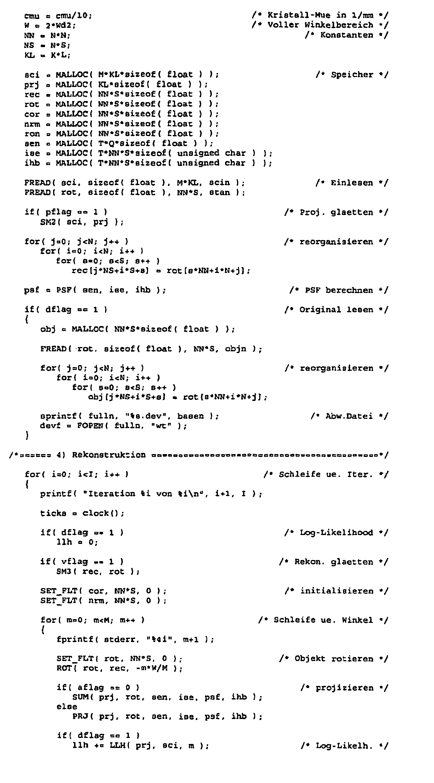
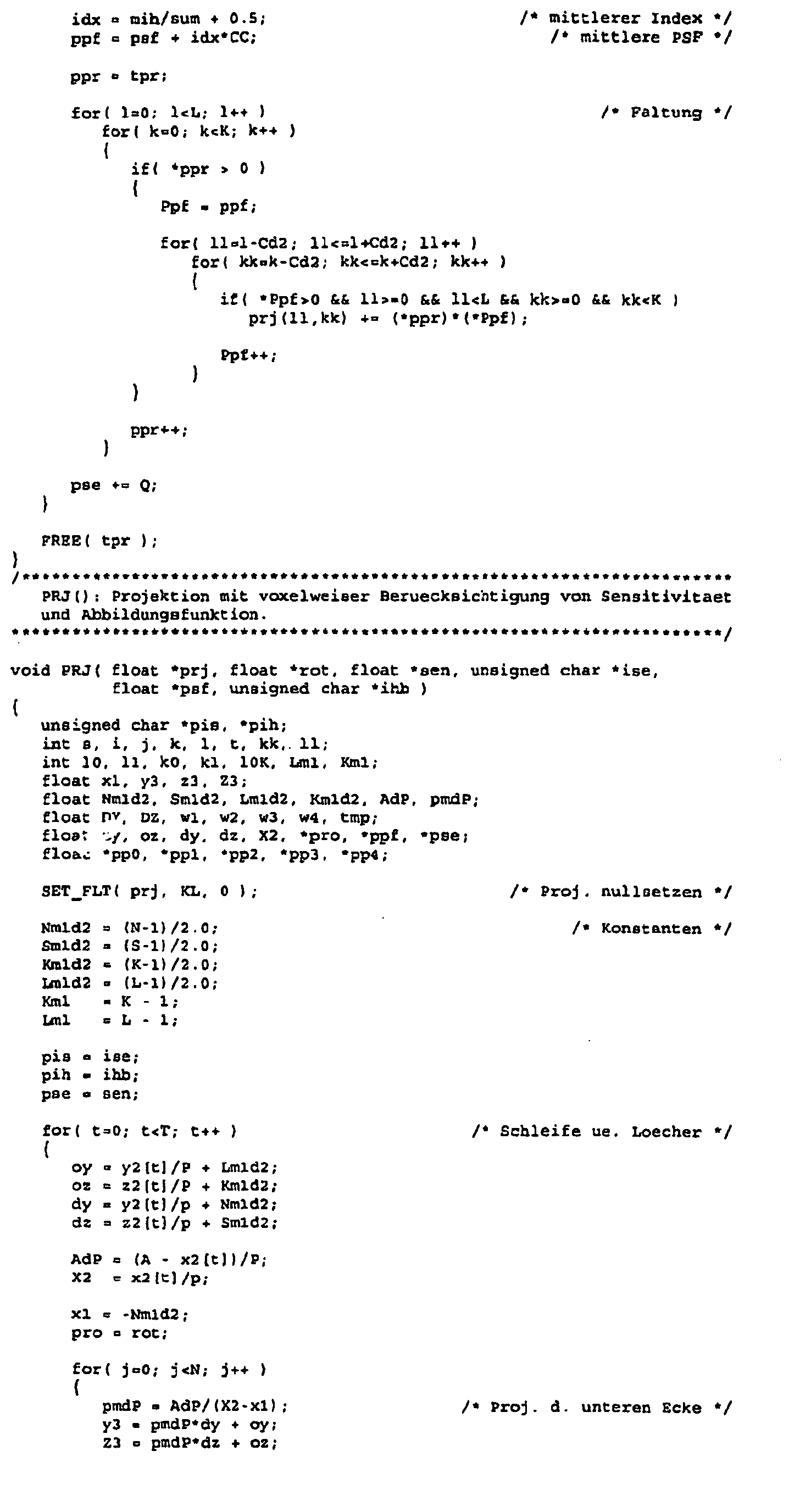
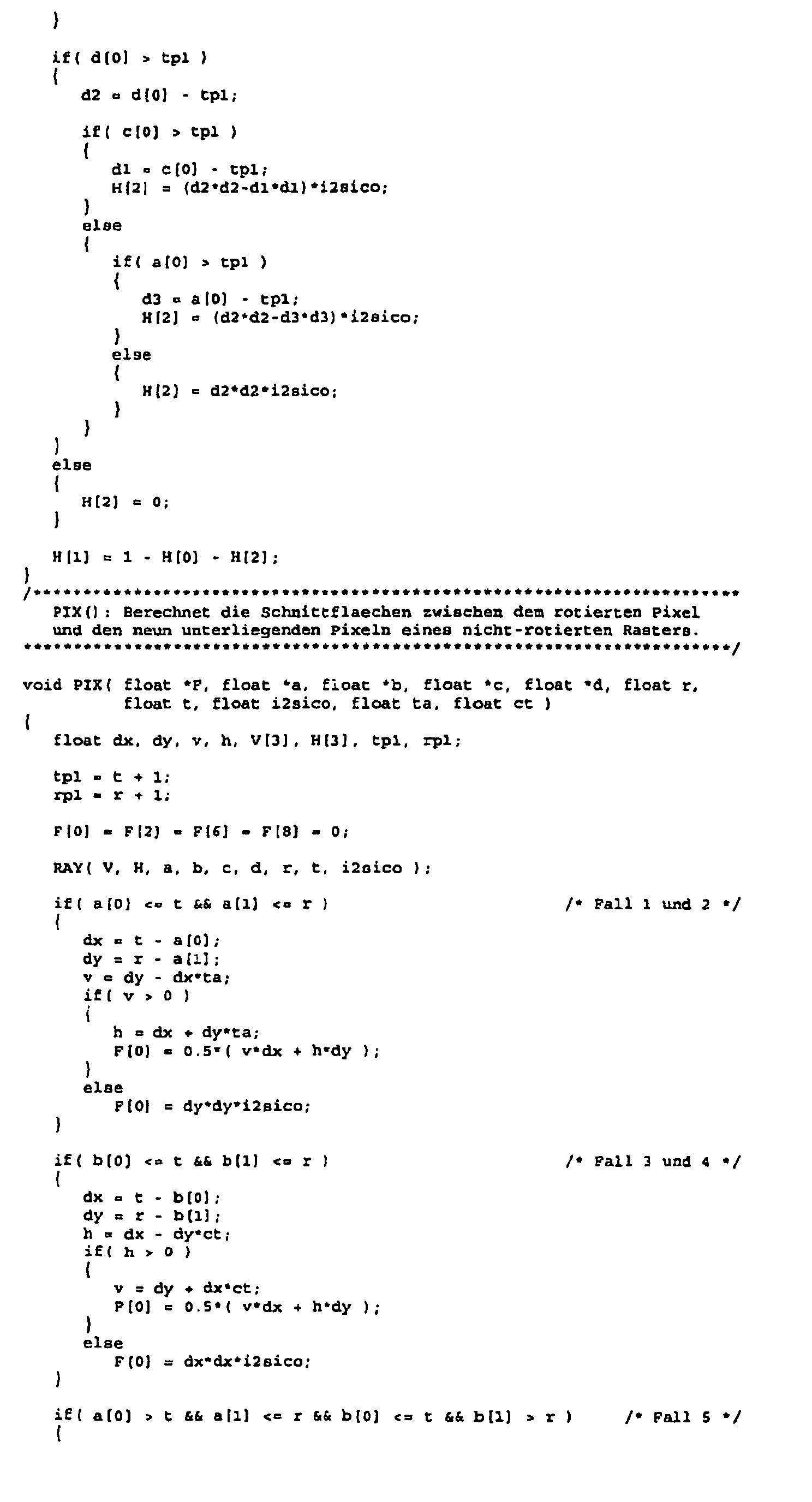
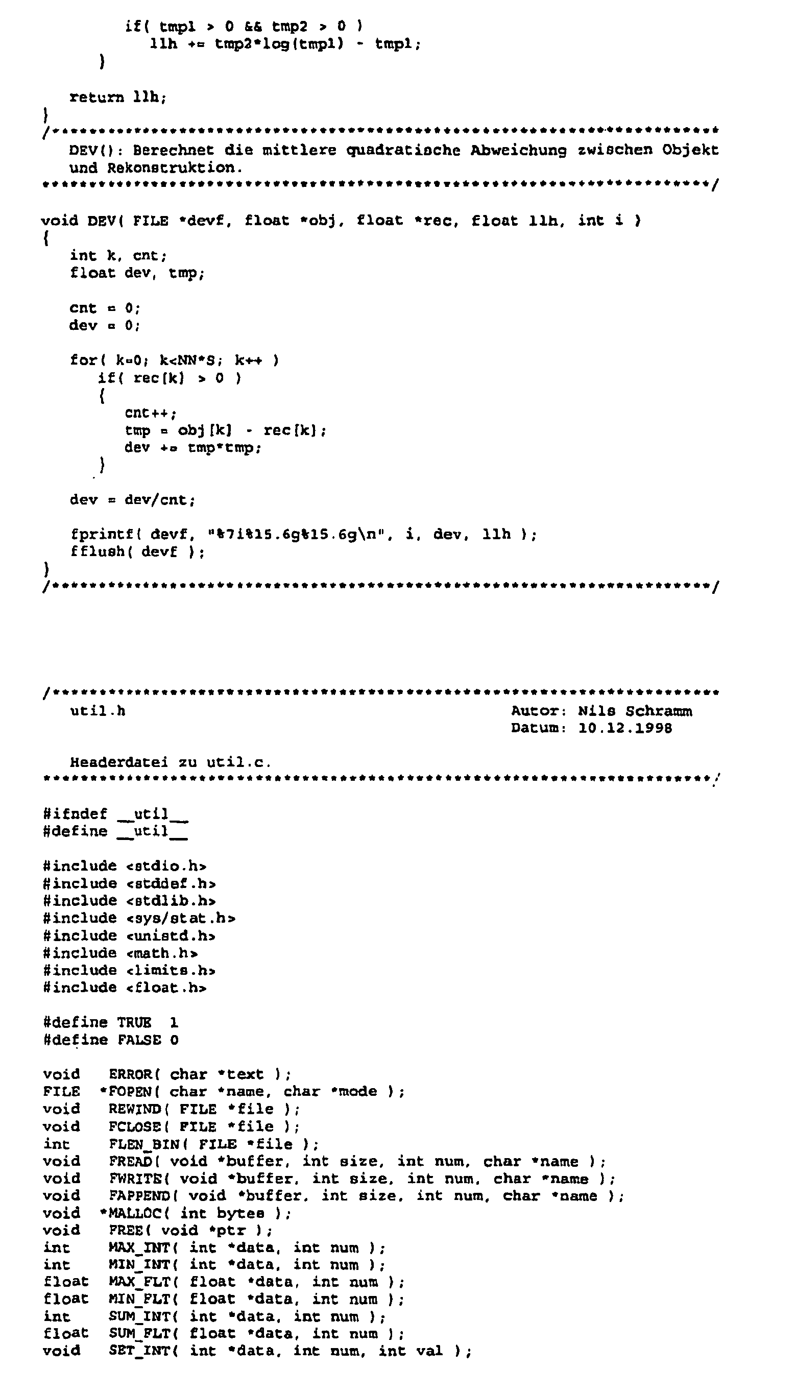
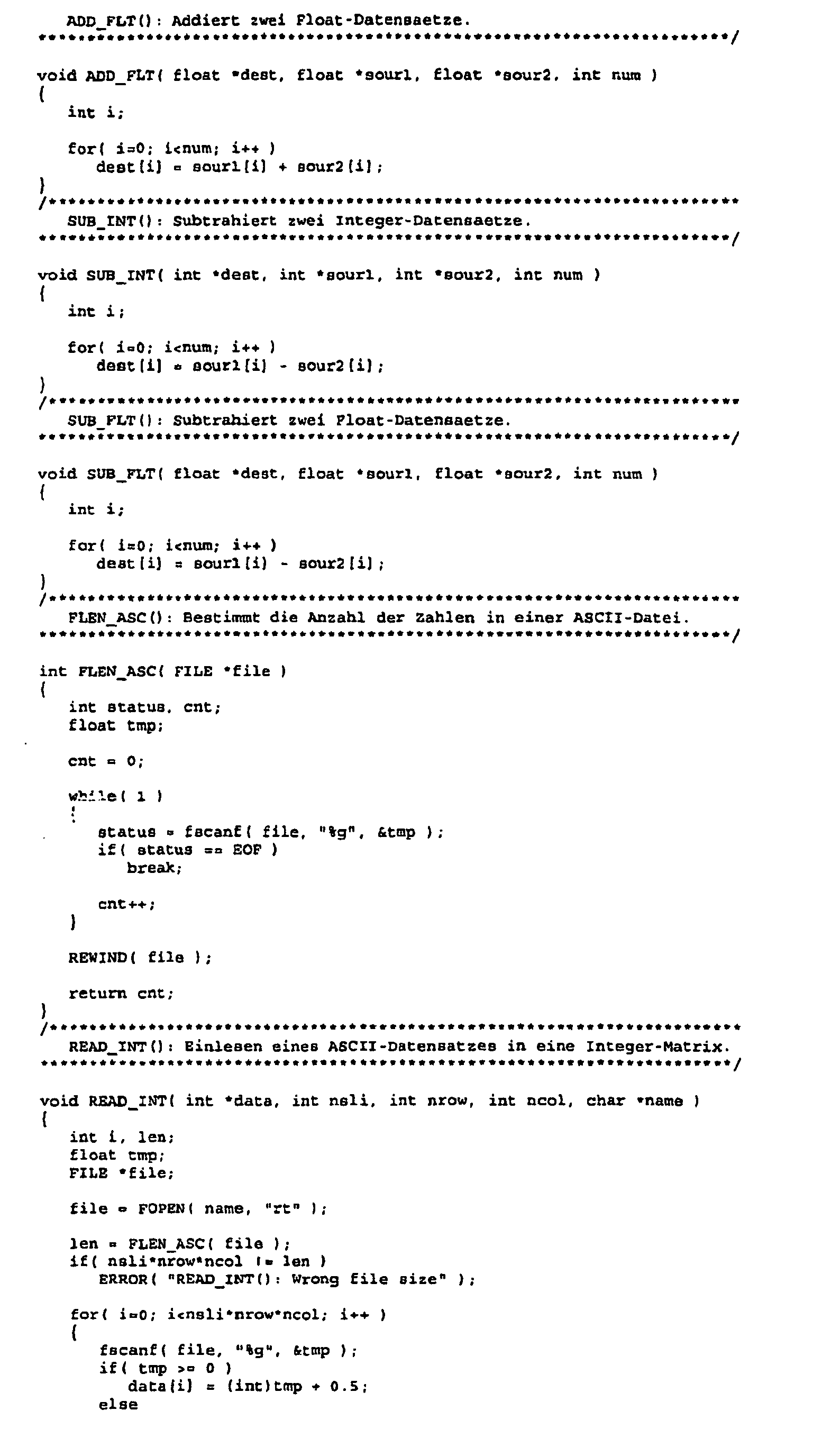
- Nachfolgend werden einschlägige Programmteile für ein Iterationsverfahren angegeben, welches die vorgenannten erfindungsgemäßen Schritte abzuarbeiten vermag. Die Programme umfassen die nachfolgend genannten Eingabe-Parameter. Ferner werden typische Werte solcher Eingabeparameter angegeben. Der Begriff "Pinhole" wird synonym für den Begriff "Loch" (des Multi-Pinhole-Kollimators) verwendet.
- Soweit die Berechnung der Kontur bzw. des Umrisses des Objekts betroffen ist, wird die Berechnung der Objektkontur in einer Ausführungsform in der "nullten" Iteration vorgenommen. Eine eigentlich die Bildqualität degradierende Eigenschaft der Comptonstreuung wird hierfür ausgenutzt: die richtungsfalsch detektierten Gammaquanten.
- Richtungsfalsch detektierte Gammaquanten stellen einen Untergrund in den Projektionen dar, der nachhaltig die Bildqualität verschlechtert. Sie können jedoch auch von Nutzen sein. Sie bewirken, dass in praktisch allen klinischen Fällen die gesamte Ausdehnung des Patienten in den Projektionen erscheint. Auch wenn sich ein Tracer, also ein Radiopharmakon sehr spezifisch an einem eng umgrenzten Organ anlagern sollte, so scheinen dennoch auch Quanten von allen anderen zur Abbildung gebrachten Bereichen des Patienten zu stammen. Tatsächlich sind dies Quanten, die ihren Ursprung in dem eng umgrenzten Organ haben, aufgrund der Comptonstreuung jedoch scheinen sie den ganzen Patienten zu "illuminieren". Dieser Umstand wird ausgenutzt, um die Objektkontur zu berechnen.
- Die Berechnung erfolgt mehrstufig:
- 1) Erstellung "binärer" Projektionen. Sie stellen eine Vereinfachung der eigentlichen Projektionen dar, insofern, dass bei ihnen jeder Pixelinhalt größer Null auf Eins gesetzt wird.
Wesentlich dafür ist eine benutzergeführte Schwellsetzung, die nach Schlüssigkeit die Projektion des eigentlichen Untersuchungsobjektes, des Patienten also, vom Hintergrund separiert. Die Berechnung der Schwelle orientiert sich an einem gemittelten Maximum, das aus sämtlichen Projektionen gebildet wird. - 2) Rückprojektion der binären Projektionen in den Objektraum.
- 3) Anhand der "Vielfachheit" der Voxel (kleines meist kubisches Volumenelement), d.i. die Häufigkeit, mit der ein Voxel unter der jeweiligen Kollimatorgeometrie über alle Winkel von den Projektionen gesehen wird, setzt eine (für die jeweilige Geometrie heuristisch ermittelte) Schwelle fest, welche Voxel in allererster Näherung zum Körperbinnenraum gehören. (Die Begrenzung des Körperbinnenraumes ist die Körperkontur.)
- 4) Mehrmalige Faltung mit 3d-Faltungskern
- 5) Wiederholung Punkt 3
- 6) Zweimaliges Durchlaufen von:
- a) 3d-Faltung
- b) Hinzunahme der Voxel, in die etwas hineingefaltet wurde, zum Körperinnenraum.
- Eine Aperturdatei hat typischerweise folgenden Aufbau:
7 45 18.435 66.503 1.5 60 22.278 21.53 27.9 45 -18.435 55.858 1.5 60 -22.278 26.164 27.9 45 36.871 13.306 1.5 60 39.33 -6.8974 27.9 45 0 2.6613 1.5 60 0 -1.3859 27.9 45 -36.871 -7.9839 1.5 60 -39.33 4.1513 27.9 45 18.435 -50.535 1.5 60 22.278 -28.355 27.9 45 -18.435 -61.181 1.5 60 -22.279 -23.889 27.9 - Beim ersten Eintrag handelt es sich um die Anzahl der Löcher. Jede folgende Zeile beschreibt ein Pinhole. Die Bedeutung der Einträge ist folgende:
Spalte Bedeutung 1 x-Koordinate des Pinholemittelpunkte, d.h. Abstand des Pinholes von der Rotationsachse in mm 2 y-Koord. des Pinholes, d.h. transversale Auslenkung des PH 3 z-Koord. des Pinholes, d.h. axiale Auslenkung den PH 4 Innendurchmesser des doppeltrichterförmigen Pinholes 5 öffnungswinkel des Pinholes in Grad 6 Seitlicher, d.h. transversaler Neigungswinkel der Pinhole-Achse 7 Axialer Neigungswinkel der PH-Achse 8 Schwächungskoeffizient des Aperturmaterials in 1/cm 












- Der grundsätzliche Aufbau der Vorrichtung wird anhand der Figur verdeutlicht.
- Ein Objekt 1 befindet sich näher an einem Multi-Pinhole Kollimator 3 als die Detektoroberfläche 2. Der Multi-Pinhole Kollimator 3 weist Löcher 4 auf, die von beiden Seiten trichterförmig in den Kollimator 3 einmünden, um so einen Durchgang von schräg auftreffenden Gammaquanten durch die Löcher zu ermöglichen. Die Spitzen 5 des Multi-Pinhole-Kollimators 3 bestehen aus Iridium. Die übrigen Bereiche des Multi-Pinhole-Kollimators 3 bestehen aus Wolfram. Gammaquanten 6 gelangen vom Objekt 1 durch die Löcher 4 hindurch auf die Detektoroberfläche 2. Das Objekt 1 wird so auf der Detektoroberfläche 2 vergrößert wiedergegeben. Zwischen den einzelnen Kegeln, die durch die Gammaquanten gebildet werden, gibt es Überschneidungsbereiche 7.
- In der Figur weisen die Löcher 4 untereinander gleichmäßige Abstände auf. Alternativ können die Abstände auch unregelmäßig sein.
| Eingabe-Aufforderung | Bedeutung |
| Projektionen (float): maus.prj | Die gemessenen Projektionen |
| Breite der Proj. [pix]: 266 | Transversale Dimension |
| Schichten in Proj. [pix]: 193 | Axiale Dimension |
| Anzahl der Winkel : 60 | Anzahl der Projektionen |
| Pixelgroesse in Proj. [mm]: 2 | Größe der Projektionspixel |
| Projektionen glaetten (nein=0/ja-1): 1 | Glättung der gemessenen Projektionen |
| Abstand RotAchse/Bildebene [mm]: 155 | Abstand Bildebene zu Rotationsachse |
| Name des Aperturmusters (text): apertur.txt | Name der Aperturdatei (siehe unten) |
| Dicke des Kristalls [mm]: 10 | Dicke des Szintillators |
| Absorption des Kristalls [1/cm]: 1.173 | Absorptionskoeffizient Kristall |
| Intrinsische Aufloesung [mm]: 3.3 | Intrinsische Auflösung der Kamera |
| Abs. Intensitaet des Gammas [%] : 90 | Abs. Intensität der Gammalinie |
| Startverteilung (float): maus.sta | Startverteilung der Rekonstruktion |
| Breite der Rekon. [pix]: 112 | Transversale Dimension |
| Schichten der Rekon. [pix]: 262 | Axiale Dimension |
| Voxelgroesse in Rekon. [mm]: 0.4 | Größe der Objektvoxel |
| Zahl der Iterationen: 30 | Anzahl der Iterationen |
| Volumen glaetten (nein=0/ja=1): 1 | Glättung der Volumendaten |
| Abbildungsfkt. voxelweise (nein=0/jasl)?: 0 | PSF voxelweise berücksichtigen oder mit mittlerer PSF falten? |
| Abw. vom Original (nein=0/ja=1)?: 0 | Abweichung zum original bestimmen? |
| Stammname des Outputs: maus | Namensstamm der Output-Dateien |
| Speichern alle?: 5 | Zwischenergebnisse speichern? |
Claims (15)
- Verfahren zur Durchführung eines tomographischen Verfahrens mit einer Vorrichtung mit einem Multi-Pinhole-Kollimator und einem Detektor zur Erfassung von Gammaquanten oder Photonen (6), die von in ein Objekt (1) gebrachten Radiopharmaka ausgesendet werden und durch den Multi-Pinhole-Kollimator (3) hindurchtreten, das Verfahren umfassend:- Ermitteln der Verteilung der Radiopharmaka in dem Objekt (1) anhand der erfassten Gammaquanten oder Photonen (6) unter Verwendung eines iterativen Rekonstruktionsverfahrens,dadurch gekennzeichnet,
dass der Multi-Pinhole-Kollimator eine Vielzahl von Löchern mit jeweiligen Positionen und Neigungen aufweist, und dass das iterative Rekonstruktionsverfahren die ortsabhängige Sensitivität und die ortsabhängige Abbildungsfunktion des Multi-Pinhole-Kollimators (3) mit beliebigen Positionen und Neigungen der Löcher berücksichtigt. - Verfahren nach Anspruch 1, wobei die Vorrichtung um das Objekt herum verfahrbar ist.
- Verfahren nach einem der Ansprüche 1-2, wobei das Rekonstruktionsverfahren die MLEM-Variante der iterativen Multi-Pinhole-Rekonstruktion ist.
- Verfahren nach einem der Ansprüche 1-3, wobei der Abstand zwischen dem Objekt (1) und dem Multi-Pinhole-Kollimator (3) kleiner ist als der Abstand zwischen dem Multi-Pinhole-Kollimator (3) und der Oberfläche (2) des Detektors.
- Verfahren nach einem der Ansprüche 1-4, bei dem die Abstände der einzelnen Löcher im Multi-Pinhole-Kollimator (3) so gewählt sind, dass sich die den Löchern zugeordneten Kegel auf der Oberfläche (2) des Detektors teilweise überschneiden.
- Verfahren nach einem der Ansprüche 1-4, bei dem die Abstände der einzelnen Löcher im Multi-Pinhole-Kollimator (3) sowie die Größe und Lage des Objekts (1) so gewählt sind, dass sich die durch Gammaquanten oder Photonen (6) gebildeten Kegel auf der Oberfläche (2) des Detektors teilweise überschneiden.
- Verfahren nach einem der Ansprüche 1-6, bei dem die Löcher (4) des Multi-Pinhole-Kollimators (3) trichterförmig in den Multi-Pinhole-Kollimator (3) einmünden.
- Verfahren nach einem der Ansprüche 1-7, wobei in dem Rekonstruktionsverfahren die Abbildungseigenschaft des Detektors und/oder die detektortypische Ungenauigkeit berücksichtigt wird.
- Verfahren nach einem der Ansprüche 1-8, wobei der äußere Umriss des Objektes (10) - vorzugsweise über die Compton-Streustrahlung - ermittelt und die Schwächung der Gammaquanten in Abhängigkeit vom Umriss kalkuliert wird.
- Computerprogramm, umfassend:- Programmteile zum Ermitteln der Verteilung von Radiopharmaka in einem Objekt (1) anhand von von in das Objekt (1) gebrachten Radiopharmaka ausgesendeten, durch einen Multi-Pinhole-Kollimator (3) hindurchtretenden und mittels eines Detektors erfassten Gammaquanten oder Photonen (6) unter Verwendung eines iterativen Rekonstruktionsverfahrens,dadurch gekennzeichnet,
dass der Multi-Pinhole-Kollimator eine Vielzahl von Löchern mit jeweiligen Positionen und Neigungen aufweist, und dass das iterative Rekonstruktionsverfahren die ortsabhängige Sensitivität und die ortsabhängige Abbildungsfunktion des Multi-Pinhole-Kollimators (3) mit beliebigen Positionen und Neigungen der Löcher berücksichtigt. - Computerprogramm nach Anspruch 10, wobei das Rekonstruktionsverfahren die MLEM-Variante der iterativen Multi-Pinhole-Rekonstruktion ist.
- Computerprogramm nach einem der Ansprüche 10-11, wobei in dem Rekonstruktionsverfahren die Abbildungseigenschaft des Detektors und/oder die detektortypische Ungenauigkeit berücksichtigt wird.
- Vorrichtung, umfassend:- Mittel zum Ermitteln der Verteilung von Radiopharmaka in einem Objekt (1) anhand von von in das Objekt (1) gebrachten Radiopharmaka ausgesendeten, durch einen Multi-Pinhole-Kollimator (3) hindurchtretenden und mittels eines Detektors erfassten Gammaquanten oder Photonen (6) unter Verwendung eines iterativen Rekonstruktionsverfahrens,dadurch gekennzeichnet,
dass der Multi-Pinhole-Kollimator eine Vielzahl von Löchern mit jeweiligen Positionen und Neigungen aufweist, und dass das iterative Rekonstruktionsverfahren die ortsabhängige Sensitivität und die ortsabhängige Abbildungsfunktion des Multi-Pinhole-Kollimators (3) mit beliebigen Positionen und Neigungen der Löcher berücksichtigt. - Vorrichtung nach Anspruch 13, wobei die Vorrichtung um das Objekt herum verfahrbar ist.
- Vorrichtung nach einem der Ansprüche 13-14, wobei das Rekonstruktionsverfahren die MLEM-Variante der iterativen Multi-Pinhole-Rekonstruktion ist.
Applications Claiming Priority (2)
| Application Number | Priority Date | Filing Date | Title |
|---|---|---|---|
| DE10142421A DE10142421A1 (de) | 2001-08-31 | 2001-08-31 | Vorrichtung für SPECT-Untersuchungen |
| EP02797567A EP1421411B1 (de) | 2001-08-31 | 2002-08-02 | Verfahren für spect-untersuchungen |
Related Parent Applications (2)
| Application Number | Title | Priority Date | Filing Date |
|---|---|---|---|
| EP02797567.1 Division | 2002-08-02 | ||
| EP02797567A Division EP1421411B1 (de) | 2001-08-31 | 2002-08-02 | Verfahren für spect-untersuchungen |
Publications (3)
| Publication Number | Publication Date |
|---|---|
| EP2045626A2 EP2045626A2 (de) | 2009-04-08 |
| EP2045626A3 EP2045626A3 (de) | 2009-12-23 |
| EP2045626B1 true EP2045626B1 (de) | 2013-06-26 |
Family
ID=7697056
Family Applications (2)
| Application Number | Title | Priority Date | Filing Date |
|---|---|---|---|
| EP08105918.0A Expired - Lifetime EP2045626B1 (de) | 2001-08-31 | 2002-08-02 | Vorrichtung für SPECT-Untersuchungen |
| EP02797567A Expired - Lifetime EP1421411B1 (de) | 2001-08-31 | 2002-08-02 | Verfahren für spect-untersuchungen |
Family Applications After (1)
| Application Number | Title | Priority Date | Filing Date |
|---|---|---|---|
| EP02797567A Expired - Lifetime EP1421411B1 (de) | 2001-08-31 | 2002-08-02 | Verfahren für spect-untersuchungen |
Country Status (7)
| Country | Link |
|---|---|
| US (1) | US7199371B2 (de) |
| EP (2) | EP2045626B1 (de) |
| AT (1) | ATE417287T1 (de) |
| DE (2) | DE10142421A1 (de) |
| DK (2) | DK2045626T3 (de) |
| ES (2) | ES2426260T3 (de) |
| WO (1) | WO2003021292A2 (de) |
Cited By (3)
| Publication number | Priority date | Publication date | Assignee | Title |
|---|---|---|---|---|
| US11439358B2 (en) | 2019-04-09 | 2022-09-13 | Ziteo, Inc. | Methods and systems for high performance and versatile molecular imaging |
| US11464503B2 (en) | 2014-11-14 | 2022-10-11 | Ziteo, Inc. | Methods and systems for localization of targets inside a body |
| US11678804B2 (en) | 2012-03-07 | 2023-06-20 | Ziteo, Inc. | Methods and systems for tracking and guiding sensors and instruments |
Families Citing this family (24)
| Publication number | Priority date | Publication date | Assignee | Title |
|---|---|---|---|---|
| DE10348868A1 (de) * | 2003-10-21 | 2005-06-16 | Forschungszentrum Jülich GmbH | T-spect |
| US7312456B2 (en) * | 2004-09-28 | 2007-12-25 | Siemens Medical Solutions Usa, Inc. | Stationary multi-pinhole cardio vascular SPECT system |
| US7635847B2 (en) * | 2005-02-11 | 2009-12-22 | The Cleveland Clinic Foundation | Non-invasive scanning device |
| CA2600654A1 (en) * | 2005-03-08 | 2006-09-14 | Adrianus A. Van Dulmen | Equipment for imaging by spect and/ or pet |
| US7989771B2 (en) * | 2005-05-13 | 2011-08-02 | Koninklijke Philips Electronics N.V. | Pinhole SPECT camera with plural detector heads |
| US7388207B1 (en) | 2006-03-28 | 2008-06-17 | University Of Utah Research Foundation | Skew slit collimator and method of use thereof |
| US20080087829A1 (en) * | 2006-04-11 | 2008-04-17 | John Hoppin | Single-photon emission computed tomography (SPECT) using helical scanning with multiplexing multi-pinhole apertures |
| US7692156B1 (en) * | 2006-08-23 | 2010-04-06 | Radiation Monitoring Devices, Inc. | Beam-oriented pixellated scintillators for radiation imaging |
| US20080048124A1 (en) * | 2006-08-25 | 2008-02-28 | General Electric Company | Multi-modality imaging system |
| US7786444B2 (en) * | 2006-11-17 | 2010-08-31 | Gamma Medica-Ideas, Inc. | Multi-aperture single photon emission computed tomography (SPECT) imaging apparatus |
| US7470907B2 (en) * | 2006-12-15 | 2008-12-30 | General Electric Company | Cross-slit collimator method and system |
| US7339174B1 (en) | 2007-02-09 | 2008-03-04 | General Electric Company | Combined slit/pinhole collimator method and system |
| US7375338B1 (en) | 2007-03-07 | 2008-05-20 | General Electric Company | Swappable collimators method and system |
| US7723690B2 (en) * | 2007-03-30 | 2010-05-25 | General Electric Company | Adjustable slit collimators method and system |
| US7569826B2 (en) * | 2007-03-30 | 2009-08-04 | General Electric Company | Adjustable collimators method and system |
| US7439514B1 (en) * | 2007-03-30 | 2008-10-21 | General Electric Company | Adjustable pinhole collimators method and system |
| US7671340B2 (en) * | 2007-07-16 | 2010-03-02 | General Electric Company | Adjustable-focal-length collimators method and system |
| HUE027888T2 (en) * | 2007-12-21 | 2016-10-28 | Milabs Bv | Focused small hole gamma detector |
| US8389943B2 (en) * | 2008-09-29 | 2013-03-05 | Siemens Medical Solutions Usa, Inc. | Modeling of the point-spread-function in single-pinhole and multi-pinhole spect reconstruction |
| CN202408923U (zh) * | 2011-11-25 | 2012-09-05 | 母治平 | 一种用于发射层析的准直装置 |
| KR101190795B1 (ko) * | 2012-04-27 | 2012-10-12 | 경북대학교 산학협력단 | 의료영상에서 장기 또는 병변의 실제 크기를 검출하는 방법 및 장치 |
| EP2823334B1 (de) | 2012-08-30 | 2016-03-23 | Mediso Orvosi Berendezés Fejlesztö És Szerviz Kft. | Bildgebungsvorrichtung, apertur für die bildgebungsvorrichtung und verfahren zur herstellung der apertur für die bildgebungsvorrichtung |
| HUP1600577A2 (en) | 2016-10-14 | 2018-06-28 | Mediso Medical Imaging Systems Kft | Imaging device with tomography apparatus |
| GB202003333D0 (en) | 2020-03-06 | 2020-04-22 | Kromek Ltd | Radiation detection system |
Family Cites Families (8)
| Publication number | Priority date | Publication date | Assignee | Title |
|---|---|---|---|---|
| US5462056A (en) | 1991-09-25 | 1995-10-31 | Siemens Medical Systems, Inc. | High-sensitivity spect imaging of small body organs using a multi-headscintillation camera with non-uniform collimation |
| US5245191A (en) * | 1992-04-14 | 1993-09-14 | The Board Of Regents Of The University Of Arizona | Semiconductor sensor for gamma-ray tomographic imaging system |
| US5821541A (en) * | 1996-02-02 | 1998-10-13 | Tuemer; Tuemay O. | Method and apparatus for radiation detection |
| US6392235B1 (en) * | 1999-02-22 | 2002-05-21 | The Arizona Board Of Regents On Behalf Of The University Of Arizona | Coded-aperture system for planar imaging of volumetric sources |
| AU2373401A (en) | 2000-01-14 | 2001-07-24 | Adrianus A Van Dulmen | Method of imaging by spect |
| US6628984B2 (en) * | 2000-04-12 | 2003-09-30 | Pem Technologies, Inc. | Hand held camera with tomographic capability |
| US6881959B2 (en) * | 2002-10-31 | 2005-04-19 | The Regents Of The University Of Michigan | Method and system for generating an image of the radiation density of a source of photons located in an object |
| US7312456B2 (en) * | 2004-09-28 | 2007-12-25 | Siemens Medical Solutions Usa, Inc. | Stationary multi-pinhole cardio vascular SPECT system |
-
2001
- 2001-08-31 DE DE10142421A patent/DE10142421A1/de not_active Withdrawn
-
2002
- 2002-08-02 DK DK08105918.0T patent/DK2045626T3/da active
- 2002-08-02 ES ES08105918T patent/ES2426260T3/es not_active Expired - Lifetime
- 2002-08-02 AT AT02797567T patent/ATE417287T1/de active
- 2002-08-02 DK DK02797567T patent/DK1421411T3/da active
- 2002-08-02 DE DE50213106T patent/DE50213106D1/de not_active Expired - Lifetime
- 2002-08-02 US US10/487,700 patent/US7199371B2/en not_active Expired - Lifetime
- 2002-08-02 WO PCT/EP2002/008604 patent/WO2003021292A2/de not_active Ceased
- 2002-08-02 EP EP08105918.0A patent/EP2045626B1/de not_active Expired - Lifetime
- 2002-08-02 ES ES02797567T patent/ES2315428T3/es not_active Expired - Lifetime
- 2002-08-02 EP EP02797567A patent/EP1421411B1/de not_active Expired - Lifetime
Cited By (6)
| Publication number | Priority date | Publication date | Assignee | Title |
|---|---|---|---|---|
| US11678804B2 (en) | 2012-03-07 | 2023-06-20 | Ziteo, Inc. | Methods and systems for tracking and guiding sensors and instruments |
| US11464503B2 (en) | 2014-11-14 | 2022-10-11 | Ziteo, Inc. | Methods and systems for localization of targets inside a body |
| US12239301B2 (en) | 2014-11-14 | 2025-03-04 | Ziteo, Inc. | Methods and systems for localization of targets inside a body |
| US11439358B2 (en) | 2019-04-09 | 2022-09-13 | Ziteo, Inc. | Methods and systems for high performance and versatile molecular imaging |
| US11883214B2 (en) | 2019-04-09 | 2024-01-30 | Ziteo, Inc. | Methods and systems for high performance and versatile molecular imaging |
| US12329551B2 (en) | 2019-04-09 | 2025-06-17 | Ziteo, Inc. | Methods and systems for high performance and versatile molecular imaging |
Also Published As
| Publication number | Publication date |
|---|---|
| ES2315428T3 (es) | 2009-04-01 |
| WO2003021292A2 (de) | 2003-03-13 |
| EP1421411A2 (de) | 2004-05-26 |
| WO2003021292A3 (de) | 2003-09-18 |
| US20040239941A1 (en) | 2004-12-02 |
| EP2045626A2 (de) | 2009-04-08 |
| DK2045626T3 (da) | 2013-09-30 |
| US7199371B2 (en) | 2007-04-03 |
| EP2045626A3 (de) | 2009-12-23 |
| ES2426260T3 (es) | 2013-10-22 |
| DE50213106D1 (de) | 2009-01-22 |
| EP1421411B1 (de) | 2008-12-10 |
| DE10142421A1 (de) | 2003-04-03 |
| DK1421411T3 (da) | 2009-04-06 |
| ATE417287T1 (de) | 2008-12-15 |
Similar Documents
| Publication | Publication Date | Title |
|---|---|---|
| EP1421411B1 (de) | Verfahren für spect-untersuchungen | |
| DE69804381T2 (de) | Bilderzeugung zur Dignostik | |
| DE102018212331A1 (de) | Strahlungstransmissions- und Fluoreszenz-Computertomographie (CT) -Bildgebungssystem und -Verfahren | |
| DE69930692T2 (de) | Gammakamera | |
| DE102008003173B4 (de) | Verfahren und Vorrichtung für die Computertomographie zur Be- | |
| DE102011004598B4 (de) | Verfahren und Computersystem zur Streustrahlkorrektur in einem Multi-Source-CT | |
| EP2847620B1 (de) | Computertomografie-verfahren und anordnung zur bestimmung von merkmalen an einem messobjekt | |
| DE102016220096B3 (de) | Verfahren zur Generierung von Röntgenbilddaten | |
| DE2657895A1 (de) | Verfahren und anordnung zur erzeugung einer darstellung der von einem objekt absorbierten strahlung | |
| DE10009285A1 (de) | Computertomograph zur Ermittlung des Impulsübertrags-Spektrums in einem Untersuchungsbereich | |
| EP0153786A2 (de) | Röntgengerät | |
| EP0028431A1 (de) | Anordnung zur Ermittlung der Streustrahlungsdichteverteilung in einem ebenen Untersuchungsbereich | |
| DE102007016370A1 (de) | Verfahren und eine Messanordnung zum Erzeugen von dreidimensionalen Bildern von Messobjekten mittels invasiver Strahlung | |
| DE2500643C2 (de) | Szintigraphie-Einrichtung mit Photovervielfachern zum Erfassen von Szintillationen in einem Szintillationskristall und einer Auswerteschaltung zum Bestimmen der Ortskoordinaten und der Amplituden der Szintillationen | |
| DE69613711T2 (de) | Pet-echtzeitabbildungsverfahren für einzelphotonen-gammakamera | |
| WO2009056094A2 (de) | Verfahren zur positronen-emissions-tomographie sowie pet-scanner | |
| DE102015225395A1 (de) | Ermittlung einer räumlichen Verteilung eines Materialeigenschaftswerts auf Basis einer Einzelenergie-Bildaufnahme | |
| DE102005048891B4 (de) | Verfahren zur Kalibrierung eines CT-Systems mit mindestens zwei winkelversetzt zueinander angeordneten Fokus/Detektorsystemen und Computertomographie-System | |
| DE2252824A1 (de) | Verfahren und geraet zum nachweis und zur messung von radioaktivitaet im menschlichen koerper | |
| DE102010061448A1 (de) | Kalibrierungsquelle und Verfahren zum Kalibrieren eines nuklearmedizinischen Bildgebungssystems | |
| DE102006019923A1 (de) | Verfahren zur Streustrahlungskorrektur bei einem Röntgen-CT und Röntgen-CT zur Anwendung dieses Verfahrens | |
| DE69732467T2 (de) | Vorrichtung und Verfahren zur Strahlungsabbildung | |
| WO2003062856A1 (de) | Vorrichtung und verfahren zum erstellen einer korrekturkennlinie für eine reduktion von artefakten bei einer tomographie | |
| DE60129105T2 (de) | Bilderzeugungssystem für spect | |
| DE102007046281A1 (de) | Verfahren und Recheneinheit zur Messung der Flussgeschwindigkeit eines Kontrastmittels in einem Gefäß eines Patienten |
Legal Events
| Date | Code | Title | Description |
|---|---|---|---|
| PUAI | Public reference made under article 153(3) epc to a published international application that has entered the european phase |
Free format text: ORIGINAL CODE: 0009012 |
|
| AC | Divisional application: reference to earlier application |
Ref document number: 1421411 Country of ref document: EP Kind code of ref document: P |
|
| AK | Designated contracting states |
Kind code of ref document: A2 Designated state(s): AT BE BG CH CY CZ DE DK EE ES FI FR GB GR IE IT LI LU MC NL PT SE SK TR |
|
| PUAL | Search report despatched |
Free format text: ORIGINAL CODE: 0009013 |
|
| AK | Designated contracting states |
Kind code of ref document: A3 Designated state(s): AT BE BG CH CY CZ DE DK EE ES FI FR GB GR IE IT LI LU MC NL PT SE SK TR |
|
| PUAF | Information related to the publication of a search report (a3 document) modified or deleted |
Free format text: ORIGINAL CODE: 0009199SEPU |
|
| PUAL | Search report despatched |
Free format text: ORIGINAL CODE: 0009013 |
|
| D17D | Deferred search report published (deleted) | ||
| AK | Designated contracting states |
Kind code of ref document: A3 Designated state(s): AT BE BG CH CY CZ DE DK EE ES FI FR GB GR IE IT LI LU MC NL PT SE SK TR |
|
| 17P | Request for examination filed |
Effective date: 20100310 |
|
| AKX | Designation fees paid |
Designated state(s): AT BE BG CH CY CZ DE DK EE ES FI FR GB GR IE IT LI LU MC NL PT SE SK TR |
|
| 17Q | First examination report despatched |
Effective date: 20110407 |
|
| GRAP | Despatch of communication of intention to grant a patent |
Free format text: ORIGINAL CODE: EPIDOSNIGR1 |
|
| GRAP | Despatch of communication of intention to grant a patent |
Free format text: ORIGINAL CODE: EPIDOSNIGR1 |
|
| INTG | Intention to grant announced |
Effective date: 20130327 |
|
| GRAS | Grant fee paid |
Free format text: ORIGINAL CODE: EPIDOSNIGR3 |
|
| GRAA | (expected) grant |
Free format text: ORIGINAL CODE: 0009210 |
|
| AC | Divisional application: reference to earlier application |
Ref document number: 1421411 Country of ref document: EP Kind code of ref document: P |
|
| AK | Designated contracting states |
Kind code of ref document: B1 Designated state(s): AT BE BG CH CY CZ DE DK EE ES FI FR GB GR IE IT LI LU MC NL PT SE SK TR |
|
| REG | Reference to a national code |
Ref country code: GB Ref legal event code: FG4D Free format text: NOT ENGLISH |
|
| RIN1 | Information on inventor provided before grant (corrected) |
Inventor name: EBEL, GERNOT Inventor name: HALLING, HORST Inventor name: SCHRAMM, NILS |
|
| REG | Reference to a national code |
Ref country code: CH Ref legal event code: EP |
|
| REG | Reference to a national code |
Ref country code: AT Ref legal event code: REF Ref document number: 618932 Country of ref document: AT Kind code of ref document: T Effective date: 20130715 |
|
| REG | Reference to a national code |
Ref country code: IE Ref legal event code: FG4D Free format text: LANGUAGE OF EP DOCUMENT: GERMAN |
|
| REG | Reference to a national code |
Ref country code: DE Ref legal event code: R096 Ref document number: 50215792 Country of ref document: DE Effective date: 20130822 |
|
| REG | Reference to a national code |
Ref country code: CH Ref legal event code: NV Representative=s name: SCHMAUDER AND PARTNER AG PATENT- UND MARKENANW, CH |
|
| REG | Reference to a national code |
Ref country code: DK Ref legal event code: T3 Effective date: 20130926 Ref country code: DK Ref legal event code: T3 |
|
| REG | Reference to a national code |
Ref country code: SE Ref legal event code: TRGR |
|
| REG | Reference to a national code |
Ref country code: ES Ref legal event code: FG2A Ref document number: 2426260 Country of ref document: ES Kind code of ref document: T3 Effective date: 20131022 |
|
| REG | Reference to a national code |
Ref country code: NL Ref legal event code: T3 |
|
| PG25 | Lapsed in a contracting state [announced via postgrant information from national office to epo] |
Ref country code: FI Free format text: LAPSE BECAUSE OF FAILURE TO SUBMIT A TRANSLATION OF THE DESCRIPTION OR TO PAY THE FEE WITHIN THE PRESCRIBED TIME-LIMIT Effective date: 20130626 Ref country code: GR Free format text: LAPSE BECAUSE OF FAILURE TO SUBMIT A TRANSLATION OF THE DESCRIPTION OR TO PAY THE FEE WITHIN THE PRESCRIBED TIME-LIMIT Effective date: 20130927 |
|
| PG25 | Lapsed in a contracting state [announced via postgrant information from national office to epo] |
Ref country code: BG Free format text: LAPSE BECAUSE OF FAILURE TO SUBMIT A TRANSLATION OF THE DESCRIPTION OR TO PAY THE FEE WITHIN THE PRESCRIBED TIME-LIMIT Effective date: 20130926 |
|
| PG25 | Lapsed in a contracting state [announced via postgrant information from national office to epo] |
Ref country code: PT Free format text: LAPSE BECAUSE OF FAILURE TO SUBMIT A TRANSLATION OF THE DESCRIPTION OR TO PAY THE FEE WITHIN THE PRESCRIBED TIME-LIMIT Effective date: 20131028 Ref country code: CZ Free format text: LAPSE BECAUSE OF FAILURE TO SUBMIT A TRANSLATION OF THE DESCRIPTION OR TO PAY THE FEE WITHIN THE PRESCRIBED TIME-LIMIT Effective date: 20130626 Ref country code: CY Free format text: LAPSE BECAUSE OF FAILURE TO SUBMIT A TRANSLATION OF THE DESCRIPTION OR TO PAY THE FEE WITHIN THE PRESCRIBED TIME-LIMIT Effective date: 20130731 Ref country code: SK Free format text: LAPSE BECAUSE OF FAILURE TO SUBMIT A TRANSLATION OF THE DESCRIPTION OR TO PAY THE FEE WITHIN THE PRESCRIBED TIME-LIMIT Effective date: 20130626 Ref country code: EE Free format text: LAPSE BECAUSE OF FAILURE TO SUBMIT A TRANSLATION OF THE DESCRIPTION OR TO PAY THE FEE WITHIN THE PRESCRIBED TIME-LIMIT Effective date: 20130626 |
|
| PG25 | Lapsed in a contracting state [announced via postgrant information from national office to epo] |
Ref country code: CY Free format text: LAPSE BECAUSE OF FAILURE TO SUBMIT A TRANSLATION OF THE DESCRIPTION OR TO PAY THE FEE WITHIN THE PRESCRIBED TIME-LIMIT Effective date: 20130626 |
|
| PG25 | Lapsed in a contracting state [announced via postgrant information from national office to epo] |
Ref country code: MC Free format text: LAPSE BECAUSE OF FAILURE TO SUBMIT A TRANSLATION OF THE DESCRIPTION OR TO PAY THE FEE WITHIN THE PRESCRIBED TIME-LIMIT Effective date: 20130626 |
|
| PLBE | No opposition filed within time limit |
Free format text: ORIGINAL CODE: 0009261 |
|
| STAA | Information on the status of an ep patent application or granted ep patent |
Free format text: STATUS: NO OPPOSITION FILED WITHIN TIME LIMIT |
|
| REG | Reference to a national code |
Ref country code: IE Ref legal event code: MM4A |
|
| 26N | No opposition filed |
Effective date: 20140327 |
|
| REG | Reference to a national code |
Ref country code: DE Ref legal event code: R097 Ref document number: 50215792 Country of ref document: DE Effective date: 20140327 |
|
| PG25 | Lapsed in a contracting state [announced via postgrant information from national office to epo] |
Ref country code: IE Free format text: LAPSE BECAUSE OF NON-PAYMENT OF DUE FEES Effective date: 20130802 |
|
| PGFP | Annual fee paid to national office [announced via postgrant information from national office to epo] |
Ref country code: SE Payment date: 20140820 Year of fee payment: 13 Ref country code: AT Payment date: 20140822 Year of fee payment: 13 |
|
| PG25 | Lapsed in a contracting state [announced via postgrant information from national office to epo] |
Ref country code: TR Free format text: LAPSE BECAUSE OF FAILURE TO SUBMIT A TRANSLATION OF THE DESCRIPTION OR TO PAY THE FEE WITHIN THE PRESCRIBED TIME-LIMIT Effective date: 20130626 |
|
| PG25 | Lapsed in a contracting state [announced via postgrant information from national office to epo] |
Ref country code: LU Free format text: LAPSE BECAUSE OF NON-PAYMENT OF DUE FEES Effective date: 20130802 |
|
| REG | Reference to a national code |
Ref country code: SE Ref legal event code: EUG |
|
| REG | Reference to a national code |
Ref country code: AT Ref legal event code: MM01 Ref document number: 618932 Country of ref document: AT Kind code of ref document: T Effective date: 20150802 |
|
| PG25 | Lapsed in a contracting state [announced via postgrant information from national office to epo] |
Ref country code: SE Free format text: LAPSE BECAUSE OF NON-PAYMENT OF DUE FEES Effective date: 20150803 Ref country code: AT Free format text: LAPSE BECAUSE OF NON-PAYMENT OF DUE FEES Effective date: 20150802 |
|
| REG | Reference to a national code |
Ref country code: FR Ref legal event code: PLFP Year of fee payment: 15 |
|
| REG | Reference to a national code |
Ref country code: FR Ref legal event code: PLFP Year of fee payment: 16 |
|
| REG | Reference to a national code |
Ref country code: FR Ref legal event code: PLFP Year of fee payment: 17 |
|
| REG | Reference to a national code |
Ref country code: GB Ref legal event code: 732E Free format text: REGISTERED BETWEEN 20190704 AND 20190710 |
|
| REG | Reference to a national code |
Ref country code: GB Ref legal event code: 732E Free format text: REGISTERED BETWEEN 20190711 AND 20190717 |
|
| REG | Reference to a national code |
Ref country code: DE Ref legal event code: R081 Ref document number: 50215792 Country of ref document: DE Owner name: LAVISION BIOTEC GMBH, DE Free format text: FORMER OWNERS: FORSCHUNGSZENTRUM JUELICH GMBH, 52428 JUELICH, DE; SCIVIS WISSENSCHAFTLICHE BILDVERARBEITUNG GMBH, 37085 GOETTINGEN, DE |
|
| PGFP | Annual fee paid to national office [announced via postgrant information from national office to epo] |
Ref country code: LU Payment date: 20190710 Year of fee payment: 13 |
|
| PGFP | Annual fee paid to national office [announced via postgrant information from national office to epo] |
Ref country code: IT Payment date: 20190821 Year of fee payment: 18 Ref country code: DK Payment date: 20190813 Year of fee payment: 18 |
|
| REG | Reference to a national code |
Ref country code: NL Ref legal event code: PD Owner name: LAVISION BIOTEC GMBH; DE Free format text: DETAILS ASSIGNMENT: CHANGE OF OWNER(S), ASSIGNMENT; FORMER OWNER NAME: SCIVIS GMBH, WISSENSCHAFTLICHE BILDVERARBEITUNG Effective date: 20191108 |
|
| REG | Reference to a national code |
Ref country code: ES Ref legal event code: PC2A Owner name: SCIVIS GMBH, WISSENSCHAFTLICHE BILDVERARBEITUNG Effective date: 20191220 |
|
| REG | Reference to a national code |
Ref country code: ES Ref legal event code: PC2A Owner name: LAVISION BIO TEC GMBH Effective date: 20191227 |
|
| REG | Reference to a national code |
Ref country code: BE Ref legal event code: PD Owner name: LAVISION BIOTEC GMBH; DE Free format text: DETAILS ASSIGNMENT: CHANGE OF OWNER(S), CESSION; FORMER OWNER NAME: SCIVIS GMBH, WISSENSCHAFTLICHE BILDVERARBEITUNG Effective date: 20191120 Ref country code: BE Ref legal event code: PD Owner name: LAVISION BIOTECH GMBH; DE Free format text: DETAILS ASSIGNMENT: CHANGE OF OWNER(S), CESSION; FORMER OWNER NAME: SCIVIS GMBH, WISSENSCHAFTLICHE BILDVERARBEITUNG Effective date: 20191120 |
|
| PGFP | Annual fee paid to national office [announced via postgrant information from national office to epo] |
Ref country code: CH Payment date: 20190819 Year of fee payment: 18 |
|
| REG | Reference to a national code |
Ref country code: CH Ref legal event code: PUE Owner name: LAVISION BIOTEC GMBH, DE Free format text: FORMER OWNER: FORSCHUNGSZENTRUM JUELICH GMBH, DE |
|
| REG | Reference to a national code |
Ref country code: DK Ref legal event code: EBP Effective date: 20200831 |
|
| REG | Reference to a national code |
Ref country code: CH Ref legal event code: PL |
|
| PG25 | Lapsed in a contracting state [announced via postgrant information from national office to epo] |
Ref country code: LI Free format text: LAPSE BECAUSE OF NON-PAYMENT OF DUE FEES Effective date: 20200831 Ref country code: CH Free format text: LAPSE BECAUSE OF NON-PAYMENT OF DUE FEES Effective date: 20200831 |
|
| REG | Reference to a national code |
Ref country code: BE Ref legal event code: MM Effective date: 20200831 |
|
| PG25 | Lapsed in a contracting state [announced via postgrant information from national office to epo] |
Ref country code: IT Free format text: LAPSE BECAUSE OF NON-PAYMENT OF DUE FEES Effective date: 20200802 |
|
| PGFP | Annual fee paid to national office [announced via postgrant information from national office to epo] |
Ref country code: FR Payment date: 20210611 Year of fee payment: 20 |
|
| PG25 | Lapsed in a contracting state [announced via postgrant information from national office to epo] |
Ref country code: DK Free format text: LAPSE BECAUSE OF NON-PAYMENT OF DUE FEES Effective date: 20200831 Ref country code: BE Free format text: LAPSE BECAUSE OF NON-PAYMENT OF DUE FEES Effective date: 20200831 |
|
| PGFP | Annual fee paid to national office [announced via postgrant information from national office to epo] |
Ref country code: NL Payment date: 20210716 Year of fee payment: 20 |
|
| PGFP | Annual fee paid to national office [announced via postgrant information from national office to epo] |
Ref country code: ES Payment date: 20210907 Year of fee payment: 20 Ref country code: GB Payment date: 20210701 Year of fee payment: 20 Ref country code: DE Payment date: 20210630 Year of fee payment: 20 |
|
| REG | Reference to a national code |
Ref country code: DE Ref legal event code: R071 Ref document number: 50215792 Country of ref document: DE |
|
| REG | Reference to a national code |
Ref country code: NL Ref legal event code: MK Effective date: 20220801 |
|
| REG | Reference to a national code |
Ref country code: GB Ref legal event code: PE20 Expiry date: 20220801 |
|
| REG | Reference to a national code |
Ref country code: ES Ref legal event code: FD2A Effective date: 20220826 |
|
| PG25 | Lapsed in a contracting state [announced via postgrant information from national office to epo] |
Ref country code: GB Free format text: LAPSE BECAUSE OF EXPIRATION OF PROTECTION Effective date: 20220801 Ref country code: ES Free format text: LAPSE BECAUSE OF EXPIRATION OF PROTECTION Effective date: 20220803 |