EP2045598A2 - Zellulärer Mikroarray und sein Mikroherstellungsverfahren - Google Patents
Zellulärer Mikroarray und sein Mikroherstellungsverfahren Download PDFInfo
- Publication number
- EP2045598A2 EP2045598A2 EP08252368A EP08252368A EP2045598A2 EP 2045598 A2 EP2045598 A2 EP 2045598A2 EP 08252368 A EP08252368 A EP 08252368A EP 08252368 A EP08252368 A EP 08252368A EP 2045598 A2 EP2045598 A2 EP 2045598A2
- Authority
- EP
- European Patent Office
- Prior art keywords
- ring
- shaped electrodes
- electrodes
- cellular microarray
- pire
- Prior art date
- Legal status (The legal status is an assumption and is not a legal conclusion. Google has not performed a legal analysis and makes no representation as to the accuracy of the status listed.)
- Withdrawn
Links
Images


Classifications
-
- B—PERFORMING OPERATIONS; TRANSPORTING
- B03—SEPARATION OF SOLID MATERIALS USING LIQUIDS OR USING PNEUMATIC TABLES OR JIGS; MAGNETIC OR ELECTROSTATIC SEPARATION OF SOLID MATERIALS FROM SOLID MATERIALS OR FLUIDS; SEPARATION BY HIGH-VOLTAGE ELECTRIC FIELDS
- B03C—MAGNETIC OR ELECTROSTATIC SEPARATION OF SOLID MATERIALS FROM SOLID MATERIALS OR FLUIDS; SEPARATION BY HIGH-VOLTAGE ELECTRIC FIELDS
- B03C5/00—Separating dispersed particles from liquids by electrostatic effect
- B03C5/02—Separators
- B03C5/022—Non-uniform field separators
- B03C5/026—Non-uniform field separators using open-gradient differential dielectric separation, i.e. using electrodes of special shapes for non-uniform field creation, e.g. Fluid Integrated Circuit [FIC]
-
- Y—GENERAL TAGGING OF NEW TECHNOLOGICAL DEVELOPMENTS; GENERAL TAGGING OF CROSS-SECTIONAL TECHNOLOGIES SPANNING OVER SEVERAL SECTIONS OF THE IPC; TECHNICAL SUBJECTS COVERED BY FORMER USPC CROSS-REFERENCE ART COLLECTIONS [XRACs] AND DIGESTS
- Y10—TECHNICAL SUBJECTS COVERED BY FORMER USPC
- Y10T—TECHNICAL SUBJECTS COVERED BY FORMER US CLASSIFICATION
- Y10T436/00—Chemistry: analytical and immunological testing
- Y10T436/25—Chemistry: analytical and immunological testing including sample preparation
- Y10T436/25375—Liberation or purification of sample or separation of material from a sample [e.g., filtering, centrifuging, etc.]
Definitions
- the present invention relates to a microarray chip and, more particularly, to a cellular microarray which is used for cellular-adhesion via dielectrophoresis.
- the cellular microarray has become a focus due to that it can be widely used in medical diagnosis, drug screening, and cellular research.
- various cells can be planted to a cellular microarray, and then reagents are delivered to the cellular microarray to test the chemical interaction with these cells.
- reagents are delivered to the cellular microarray to test the chemical interaction with these cells.
- the cellular microarray can be employed in research and in clinical application to save time and improve the screening efficiency.
- planting cells by point to point through arrayers to manufacture the general cellular microarray is very time-consuming (about ten hours to several days) and extremely expensive.
- the cellular microarray has the potential for widely-spread application, it is difficult to employe the cellular microarray in research and clinical application at a large scale.
- Pethig et al have disclosed a method for manipulation of particles.
- the particles may be solid, semi-solid or liquid, and may be of simple materials or may be biological particles such as whole cells or fragments thereof.
- D. R. Albrecht et al. have disclosed two independent methods for creating living cell arrays that are encapsulated within a poly(ethylene glycol)-based hydrogel to create a local 3-D microenvironment ( D. R. Albrecht, et al. Lab Chip. 2005, 5, 111-118 ).
- photopatterning selectively crosslinks hydrogel microstructures containing living cells with ⁇ 100 ⁇ m feature size.
- electrolyning utilizes dielectrophoretic forces to position cells within a prepolymer solution prior to crosslinking, forming cell patterns with micron resolution.
- D. R. Albrecht et al. have provided a method for the rapid formation of reproducible, high-resolution 3D cellular structures within a photopolymerizable hydrogel using dielectrophoretic forces ( D. R. Albrecht, et al. Nat Methods. 2006, 3, 369-375 ). It shows that the parallel formation of >20,000 cell clusters of precise size and shape within a thin 2-cm 2 hydrogel and the maintenance of high cell viability and differentiated cell markers over 2 weeks. By modulating cell-cell interactions in 3D clusters, the results show that microscale tissue organization regulates bovine articular chondrocyte biosynthesis. Hence, this platform permits investigation of tissue architecture in other multicellular processes, from embryogenesis to regeneration to tumorigenesis.
- D. R. Albrecht et al. have also provide a method to form multiphase tissues consisting of microscale tissue sub-units in a "local phase” biomaterial, which are organized by dielectrophoresis (DEP) forces in a separate, mechanically supportive "bulk phase” material ( D. R. Albrecht, et al. Lab Chip. 2007, 7, 702-709 ).
- D. R. Albrecht et al. define the effects of medium conductivity on the speed and quality of DEP cell patterning.
- D. R. Albrecht et al. produce multiphase tissues with microscale architecture that combine high local hydrogel conductivity for enhanced survival of sensitive liver progenitor cells with low bulk conductivity required for efficient DEP micropatterning. This approach enables an expanded range of studies examining the influence of 3D cellular architecture on diverse cell types, and in the future may improve the biological function of inhomogeneous tissues assembled from a variety of modular tissue sub-units.
- Y Huang et al. disclosed a microelectronic chip array on a silicon wafer fabricated by semiconductor manufacturing process.
- the disclosed microelectronic chip array includes plate-electrodes, and agarose covered thereon and functions as a cell adhesion layer. Since different cells have different dielectrophoresis properties, this microelectronic chip array is capable of separating various cells by adjusting the voltage ( Y. Huang, et al. Anal. Chem. 2002, 74, 3362-3371 ).
- Y. Huang et al. The purpose of Y. Huang et al. is to screen a specific cell type in heterogeneous cells. Therefore, it is possible to screen a specific cell type from heterogeneous cells successfully and to generate the gene expression profile of the specific cell type correctly by using the plate-electrodes.
- the disadvantage of the plate-electrodes is that the distribution of the cells on the electrodes is not uniform, and parts of the electrodes are not adhered with cells.
- C. T. Ho et al. has disclosed a cell-patterning chip, which was manufactured by a microfabrication process. On the cell-patterning chip, many concentric electrodes were formed to mimic the lobular morphology of real liver tissue ( C. T. Ho, et al. Lab Chip. 2006, 6, 724-734 ).
- the applied cell adhesion layer of the cell-patterning chip is poly-D-lysine.
- many anodes and cathodes were arranged in parallel on the cell-patterning chip to form the concentric electrodes. When ac voltage was applied, the dielectrophoresis force was formed within the cells in the electric field, and the cells were able to distribute on all electrodes of the concentric electrodes.
- the cell-patterning chip was able to mimic the lobular morphology of real liver tissue artificially.
- the result of cell survival rate test showed that most of the cells were still alive on the electrodes after 1 hour.
- a cellular microarray to overcome the disadvantages illustrated above.
- a cellular microarray where the cells can be patterned with good uniformity rapidly, is needed.
- the cost for manufacturing and using the cellular microarray must be reduced, so that it is possible to apply the cellular microarray in research and clinical application widely.
- the object of the present invention is to provide a cellular microarray, which can adhere cells rapidly and uniformly, simplify the manufacturing process, increase the output of manufacturing, and reduce the cost for manufacturing and application.
- the cellular microarray of the present invention includes: a substrate; a plurality of first conductive lines, which locate on a surface of the substrate; a plurality of second conductive lines, which locate on the surface of the substrate, and the second conductive lines are electrically disconnected to the first conductive lines; and a plurality of planar interdigitated ring electrodes (PIREs).
- the PIREs are arranged on the surface of the substrate in an array, and each PIRE comprises a plurality of first ring-shaped electrodes and a plurality of second ring-shaped electrodes.
- Both of the first ring-shaped electrodes and the second ring-shaped electrodes are located on the surface of the substrate, and the first ring-shaped electrodes and the second ring-shaped electrodes of each PIRE are arranged alternately on the surface of the substrate. Further, the first conductive lines are electrically connected to the first ring-shaped electrodes of each PIRE, and the second conductive lines are electrically connected to the second ring-shaped electrodes of each PIRE. In addition, the electrical polarities of the outermost ring electrodes of every two adjacent PIREs are different.
- the substrate of the cellular microarray there is no specific limitation for the substrate of the cellular microarray according to the present invention.
- the substrate may be a transparent substrate, or a silicon substrate.
- the transparent substrate used in the cellular microarray of the present invention is unlimited.
- the transparent substrate may be glass substrate, or transparent resin substrate.
- the first ring-shaped electrodes and the second ring-shaped electrodes of the same PIRE are not electrically connected to each other. After a different voltage is applied, an electric field is formed between the first ring-shaped electrodes and the second ring-shaped electrodes, and cells are adhered to a cell adhesion layer of the PIREs via dielectrophoresis force.
- the first ring-shaped electrodes and the second ring-shaped electrodes of the same PIRE are extended from and connected to the first conductive lines and the second conductive lines, wherein the first ring-shaped electrodes and the second ring-shaped electrodes are disposed corresponding to each other or surround each other.
- the outermost ring-shaped electrodes of the same PIRE may be the first ring-shaped electrodes of the second ring-shaped electrodes.
- the outermost ring-shaped electrodes of the adjacent PIREs are the first ring-shaped electrodes or the second ring-shaped electrodes alternately.
- the sizes and the shapes of the adjacent PIRE of the cellular microarray there is no specific limitation for the sizes and the shapes of the adjacent PIRE of the cellular microarray according to the present invention.
- the sizes and the shapes of any two adjacent PIREs are the same.
- the shapes of the PIRE of the cellular microarray are unlimited.
- the edges of the PIRE form a polygon, a circle, or an ellipse.
- the shapes of the first ring-shaped electrodes or the second ring-shaped electrodes in the same PIRE of the cellular microarray may be identical or different.
- the shapes of the first ring-shaped electrodes or the second ring-shaped electrodes are the same.
- the shapes of the first ring-shaped electrodes or the second ring-shaped electrodes are linear electrodes, poly-segmental electrodes, or arc-shaped electrodes.
- the arrangement of the first ring-shaped electrodes and the second ring-shaped electrodes are unlimited.
- the first ring-shaped electrodes and the second ring-shaped electrodes are arranged in a form of concentric circles, or comb-shapes.
- the gaps between the first ring-shaped electrodes or the second ring-shaped electrodes of the same PIRE is unlimited.
- the gaps between the first ring-shaped electrodes and the adjacent second ring-shaped electrodes of each PIRE are the same, or the gaps between the first ring-shaped electrodes and the adjacent second ring-shaped electrodes of each PIRE increase in a direction from inner electrodes to outer electrodes.
- widths of the first ring-shaped electrodes and widths of the second ring-shaped electrodes of the same PIRE are not limited.
- widths of the first ring-shaped electrodes and widths of the adjacent second ring-shaped electrodes of the same PIRE are the same.
- widths of the ring-shaped electrodes and widths of the adjacent second ring-shaped electrodes of each PIRE are the same.
- the amounts of the first ring-shaped electrodes and the second ring-shaped electrodes of the same PIRE are not limited.
- the amounts of the first ring-shaped electrode and the second ring-shaped electrodes of the adjacent PIRE are the same.
- the edges of the first ring-shaped electrodes of the PIRE may further comprise thorns selectively to increase the electric field during using the cellular microarray so as to enhance the capacity of cell adhesion via dielectrophoresis force.
- the edges of the second ring-shaped electrodes of the PIRE may further comprise thorns selectively to increase the electric field during using the cellular microarray so as to enhance the capacity of cell adhesion via dielectrophoresis force.
- the distances between the adjacent thorns of the first ring-shaped electrodes are not limited.
- every distance between the adjacent thorns of the first ring-shaped electrodes is the same.
- the distances between the adjacent thorns of the second ring-shaped electrodes are not limited.
- every distance between the adjacent thorns of the second ring-shaped electrodes is the same.
- the array which is formed by the arrangement of the PIREs on the substrate, is not limited.
- the PIREs form an m x n array, and each m and n is independently an integer of 1 or more.
- the first conductive lines and the second conductive lines of the cellular microarray are arranged unlimitedly.
- the first conductive lines and the second conductive lines are arranged alternately on the surface of the substrate, and each PIRE is set between the first conductive line and the second conductive line. More preferably, the first conductive lines and the second conductive lines are parallel with each other.
- the shapes of the first conductive lines and the second conductive lines are not limited.
- the shapes of the first conductive lines and the second conductive lines are linear lines, poly-segmental lines, or curved lines.
- the material of the first conductive lines or the second conductive lines, which are electrical connected to the PIREs are unlimited.
- the material of the first conductive lines or the second conductive lines is metal or transparent electrode material.
- the transparent electrode material used in the first conductive lines or the second conductive lines of the cellular microarray is unlimited.
- the transparent electrode material is ITO or IZO.
- the material of the first ring-shaped electrodes and the second ring-shaped electrodes is not limited.
- the first ring-shaped electrodes or the second ring-shaped electrodes are metal electrodes or transparent electrodes.
- the transparent electrodes used in the cellular microarray of the present invention are unlimited.
- the transparent electrodes are ITO electrodes or IZO electrodes.
- the cellular microarray of the present invention may further comprise a cell adhesion layer, which locates on a surface of the each PIRE or on the surface of the substrate, so that cells or culture matrixes may adhere or bind to the cell adhesion layer.
- the cellular microarray of the present invention may further comprise a concentration gradient generator, which locates above the surface of the substrate to protect the substrate and the plurality of PIREs.
- the cellular microarray of the present invention may further comprise a concentration gradient generating channel, and a plurality of flow paths selectively. The concentration gradient generating channel and the flow paths can control the concentration of cells or culture matrixes, which flow into the cell adhesion layer on the surfaces of each electrode of the PIREs.
- the concentration gradient generating channel and the flow paths are disposed on the surface of the substrate, and the flow paths are connected to the concentration gradient generating channel and the PIREs.
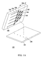
- a cellular microarray 100 comprises a substrate 101, 411, a concentration gradient generating channel 103, repeats of flow paths 107, repeats of first conductive lines 111, repeats of second conductive lines 112, repeats of planar interdigitated ring electrodes (PIREs) 113,and a cell adhesion layer 461.
- PIREs planar interdigitated ring electrodes
- the concentration gradient generating channel103, flow paths 107, first conductive lines 111, second conductive lines 112, the PIREs 113, the cell adhesion layer 461, and the concentration gradient generating channel of the cellular microarray 100 are disposed on the surface of the substrate 101, 411.
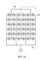
- FIG.1B is the enlarged view of the electrode array 109 of the cellular microarray 100 in FIG. 1A .
- the flow paths 107 are connected to the concentration gradient generating channels 103 and the PIREs 113.
- the buffer flows from the concentration gradient generating channels 103 to the PIREs 113 through flow paths 107.
- different PIREs 113 are distributed over the buffer with different concentration.
- the PIREs 113 are made of ITO to form the transparent electrodes.
- the PIREs 113 are arranged to form a 6 x 6 array on the surface of the substrates 101, and the PIREs 113 are disposed between the first conductive lines 111 and the second conductive lines 112.
- the first conductive lines 111 and the second conductive lines 112, which are disposed on the surface of the substrate 101, are interdigitated, so the first conductive lines 111 and the second conductive lines 112 are not electrically connected to each other.
- the first conductive line 211 is electrically connected to the first ring-shaped electrode 221 of the PIRE 213 (i.e. the outer ring-shaped electrode 221 in the PIRE 213), and the second conductive line 212 is electrically connected to the second ring-shaped electrode 222 of the PIRE 213 (i.e. the inner ring-shaped electrode 222 of the PIRE 213).
- the first conductive line 211 is electrically connected to the first ring-shaped electrode 224 of the PIRE 214 (i.e.
- the PIREs 213, 214 comprise outer ring-shaped electrodes 221, 223 and inner ring-shaped electrodes 222, 224.
- the widths of the outer ring-shaped electrodes 221, 223 and the inner ring-shaped electrodes 222, 224 are identical.
- outer ringring-shaped electrode 221 and the inner ringring-shaped electrode 222 are interdigitated, and arranged in a form of concentric circles on the surface of the substrate. Besides, the gaps between the outer ring-shaped electrode 221 and the inner ring-shaped electrode 22 are increased in radial direction.
- the first conductive lines 111 are connected to an AC signal
- the second conductive lines 112 are connected to the ground.
- an AC signal is applied to the PIREs
- an electrical potential difference is formed between the outer ring-shaped electrodes of the adjacent PIREs 113, 114.
- the outer ring-shaped electrode 301 and inner ring-shaped electrode 302 of the PIRE comprises thorns 311, 312.
- the function of the thorns 311, 312 is to enhance the electric-field.
- the thorns 311, 312 can achieve localized maximum electric-field on the edges of the ring-shaped electrodes, so that cells can be trapped to the electrodes more easily.
- the cell adhesion layer 461 of the cellular microarray is disposed on the surface of each PIRE 421 to improve cell adhesion.
- the material of the cell adhesion layer 461 is type one collagen.
- the cellular microarray chip further comprises a concentration gradient generator 452 to form enclosed channels/chambers for cellular assays.
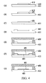
- a layer of ITO film 413 which is used to form electrodes, is coated on the substrate 411.
- a photoresist 412 is coated on the ITO film 413.
- the ITO film 413 was micromachined using argon plasma etching to form PIREs 421 (as shown in FIG. 4B ).
- the photoresist 412 is then stripped off in acetone (as shown in FIG. 4C ).
- another photoresist 441 is coated on the substrate 411 (as shown in FIG. 4D ).
- Oxygen plasma is applied to bond a concentration gradient generator 452 to the substrate with micromachined ITO film 413, wherein the concentration gradient generator 452 is made of PDMS.
- Inlets for cell injection are formed (as shown in FIG. 4E ) by punching holes (not whon in FIG. 4E ) on the concentration gradient generator 452.
- the cellular microarray is incubated in collagen 461 (10 ⁇ m/mL, 37°C, 1 hour). Photoresist 441 is removed by ultrasonic agitation in ethanol for 10 min, which may reduce the possible denaturation of collagen comparing to acetone (as shown in FIG. 4G ).
- the cellular microarray, which is coated with collagen is flushed in DI water followed by nitrogen drying.
- dielectrophoresis cell patterning The process for dielectrophoresis cell patterning is described as follows. First, the dielectrophoresis cell patterning buffer (10 mM HEPES, 55 mM D-glucose, 221 mM Sucrose, 1% penicillin/streptomycin, 0.5 mM EGTA; pH 7.0, 300 Osm, 228 ⁇ S/cm) was meticulously prepared to ensure long-term cell viability. Cells suspended in the buffer were successively injected into the chamber of the cellular microarray. Then, AC signal (5 Vpp, 5 MHz) was applied to the cellular microarray to pattern cells.
- the dielectrophoresis cell patterning buffer (10 mM HEPES, 55 mM D-glucose, 221 mM Sucrose, 1% penicillin/streptomycin, 0.5 mM EGTA; pH 7.0, 300 Osm, 228 ⁇ S/cm
- AC signal 5 Vpp, 5
- Ca 2+ -containing buffer (1.8 mM CaCl 2 , 274 ⁇ S/cm), without EGTA, was injected to sweep away the off-electrode cells, and to promote cell adhesion on the collagen.
- the AC signal was removed.
- the Ca 2+ -containing buffer and the dielectrophoresis cell patterning buffer were replaced with Dulbecco's modified Eagle's medium with 10% fetal bovine serum and 1% penicillin/streptomycin. Finally, the cellular microarray with the patterned cells was incubated at 37°C.
- the HepG2 were injected into the cellular microarray.
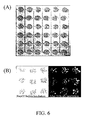
- the HepG2 were patterned as cellular microaray via dielectrophoresis force (cell seeding density was 5 million cells/ml; the applied voltage was 5 Vpp, 5MHz).
- FIG. 6A HepG2 were distributed on PIREs with good uniformity.
- a cell pattern with good uniformity can be obtained by using the cellular microarray chip in the present embodiment.
- most HepG2 were stained positively with calcein AM (the fluorescent stain for live cells) as shown in FIG. 6B which means that the patterned cells show long-term cell viability on the cellular microarray after 24 hours.
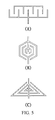
- the structure of the cellular microarray and the manufacturing method is the same as described in embodiment 1, except that the shape of the PIRE is designed in a comb-shaped electrode in the present embodiment, as shown in FIG. 5A .
- the structure of the cellular microarray and the manufacturing method is the same as described in embodiment 1, except that the shape of the PIRE is designed in a hexagonal electrode in the present embodiment, as shown in FIG. 5B .
- the structure of the cellular microarray and the manufacturing method is the same as described in embodiment 1, except that the shape of the PIRE is designed in a triangle electrode in the present embodiment, as shown in FIG. 5C .
- the structure of the cellular microarray and the manufacturing method is the same as described in embodiment 1, except that the gaps between the outer ring-shaped electrodes and the inner ring-shaped electrodes of each PIRE are the same.
- the structure of the cellular microarray and the manufacturing method is the same as described in embodiment 1, except that the first conductive lines and the second conductive lines are poly-segmental.
- the structure of the cellular microarray and the manufacturing method is the same as described in embodiment 1, except that the material of the electrodes are metal, such as aluminum or chromium.
Landscapes
- Engineering & Computer Science (AREA)
- Microelectronics & Electronic Packaging (AREA)
- Apparatus Associated With Microorganisms And Enzymes (AREA)
Applications Claiming Priority (1)
| Application Number | Priority Date | Filing Date | Title |
|---|---|---|---|
| TW096137479A TWI375023B (en) | 2007-10-05 | 2007-10-05 | A cellular microarray and its microfabrication method |
Publications (2)
| Publication Number | Publication Date |
|---|---|
| EP2045598A2 true EP2045598A2 (de) | 2009-04-08 |
| EP2045598A3 EP2045598A3 (de) | 2009-12-16 |
Family
ID=40291001
Family Applications (1)
| Application Number | Title | Priority Date | Filing Date |
|---|---|---|---|
| EP08252368A Withdrawn EP2045598A3 (de) | 2007-10-05 | 2008-07-10 | Zellulärer Mikroarray und sein Mikroherstellungsverfahren |
Country Status (3)
| Country | Link |
|---|---|
| US (1) | US7919048B2 (de) |
| EP (1) | EP2045598A3 (de) |
| TW (1) | TWI375023B (de) |
Cited By (2)
| Publication number | Priority date | Publication date | Assignee | Title |
|---|---|---|---|---|
| CN110168364A (zh) * | 2019-03-27 | 2019-08-23 | 京东方科技集团股份有限公司 | 生物检测芯片、生物检测装置及其检测方法 |
| CN115007233A (zh) * | 2017-10-18 | 2022-09-06 | 核酸有限公司 | 包括具有薄膜晶体管和电容感测的双基底的数字微流体设备 |
Families Citing this family (14)
| Publication number | Priority date | Publication date | Assignee | Title |
|---|---|---|---|---|
| US6911132B2 (en) | 2002-09-24 | 2005-06-28 | Duke University | Apparatus for manipulating droplets by electrowetting-based techniques |
| US7329545B2 (en) * | 2002-09-24 | 2008-02-12 | Duke University | Methods for sampling a liquid flow |
| CA2594483C (en) * | 2005-01-28 | 2014-08-26 | Duke University | Apparatuses and methods for manipulating droplets on a printed circuit board |
| WO2009021233A2 (en) | 2007-08-09 | 2009-02-12 | Advanced Liquid Logic, Inc. | Pcb droplet actuator fabrication |
| US8598018B2 (en) | 2010-06-22 | 2013-12-03 | International Business Machines Corporation | Forming an electrode having reduced corrosion and water decomposition on surface using a custom oxide layer |
| US8940148B2 (en) | 2010-06-22 | 2015-01-27 | International Business Machines Corporation | Nano-fluidic field effective device to control DNA transport through the same |
| US8354336B2 (en) | 2010-06-22 | 2013-01-15 | International Business Machines Corporation | Forming an electrode having reduced corrosion and water decomposition on surface using an organic protective layer |
| US11198126B2 (en) * | 2011-10-31 | 2021-12-14 | Fluid-Screen, Inc. | Apparatus for pathogen detection |
| WO2016104517A1 (ja) | 2014-12-26 | 2016-06-30 | 株式会社 東芝 | バイオセンサ |
| EP3144674B1 (de) | 2015-09-18 | 2020-12-02 | Hochschule Kaiserslautern University of Applied Sciences | Upside-down-mikroelektrodenanordnung für einzel- und mehrzellenkulturen |
| KR101753839B1 (ko) * | 2015-11-09 | 2017-07-05 | 한국과학기술연구원 | 비드를 이용한 초고감도 전기화학 바이오 센서 및 그 제조 방법 |
| CN107271706B (zh) * | 2017-07-05 | 2018-11-06 | 大连理工大学 | 一种实时精准控制观测点动态生化因子浓度的微流控芯片 |
| JP6981650B2 (ja) * | 2017-12-22 | 2021-12-15 | 国立大学法人東北大学 | 培養装置 |
| TWI912026B (zh) * | 2024-11-22 | 2026-01-11 | 瑞禾生物科技股份有限公司 | 用於生物粒子之操作裝置 |
Citations (3)
| Publication number | Priority date | Publication date | Assignee | Title |
|---|---|---|---|---|
| US5795457A (en) | 1990-01-30 | 1998-08-18 | British Technology Group Ltd. | Manipulation of solid, semi-solid or liquid materials |
| US6936151B1 (en) | 1999-07-20 | 2005-08-30 | University Of Wales, Bangor | Manipulation of particles in liquid media |
| WO2007079663A1 (en) | 2006-01-06 | 2007-07-19 | Capitalbio Corporation | Methods for improving efficiency of cell electroporation using dielectrophoreses |
Family Cites Families (5)
| Publication number | Priority date | Publication date | Assignee | Title |
|---|---|---|---|---|
| US6149789A (en) * | 1990-10-31 | 2000-11-21 | Fraunhofer Gesellschaft Zur Forderung Der Angewandten Forschung E.V. | Process for manipulating microscopic, dielectric particles and a device therefor |
| DE60130052T2 (de) * | 2000-04-13 | 2008-05-15 | Wako Pure Chemical Industries, Ltd. | Elektroden-Bau für dielektrophoretische Anordnung und dielektrophoretische Trennung |
| JP2004503775A (ja) * | 2000-06-14 | 2004-02-05 | ボード・オブ・リージェンツ,ザ・ユニヴァーシティ・オヴ・テキサス・システム | 検体混合物の組み合わせた磁気泳動および誘電泳動の操作のための方法および装置 |
| ITBO20050481A1 (it) * | 2005-07-19 | 2007-01-20 | Silicon Biosystems S R L | Metodo ed apparato per la manipolazione e/o l'individuazione di particelle |
| DE102006002462A1 (de) * | 2006-01-18 | 2007-07-19 | Evotec Technologies Gmbh | Elektrischer Feldkäfig und zugehöriges Betriebsverfahren |
-
2007
- 2007-10-05 TW TW096137479A patent/TWI375023B/zh not_active IP Right Cessation
-
2008
- 2008-04-25 US US12/149,030 patent/US7919048B2/en not_active Expired - Fee Related
- 2008-07-10 EP EP08252368A patent/EP2045598A3/de not_active Withdrawn
Patent Citations (3)
| Publication number | Priority date | Publication date | Assignee | Title |
|---|---|---|---|---|
| US5795457A (en) | 1990-01-30 | 1998-08-18 | British Technology Group Ltd. | Manipulation of solid, semi-solid or liquid materials |
| US6936151B1 (en) | 1999-07-20 | 2005-08-30 | University Of Wales, Bangor | Manipulation of particles in liquid media |
| WO2007079663A1 (en) | 2006-01-06 | 2007-07-19 | Capitalbio Corporation | Methods for improving efficiency of cell electroporation using dielectrophoreses |
Non-Patent Citations (4)
| Title |
|---|
| D. R. ALBRECHT ET AL., LAB CHIP., vol. 5, 2005, pages 111 - 118 |
| D. R. ALBRECHT ET AL., LAB CHIP., vol. 7, 2007, pages 702 - 709 |
| D. R. ALBRECHT ET AL., NAT METHODS., vol. 3, 2006, pages 369 - 375 |
| Y. HUANG ET AL., ANAL. CHEM., vol. 74, 2002, pages 3362 - 3371 |
Cited By (3)
| Publication number | Priority date | Publication date | Assignee | Title |
|---|---|---|---|---|
| CN115007233A (zh) * | 2017-10-18 | 2022-09-06 | 核酸有限公司 | 包括具有薄膜晶体管和电容感测的双基底的数字微流体设备 |
| CN115007233B (zh) * | 2017-10-18 | 2023-11-10 | 核蛋白有限公司 | 包括具有薄膜晶体管和电容感测的双基底的数字微流体设备 |
| CN110168364A (zh) * | 2019-03-27 | 2019-08-23 | 京东方科技集团股份有限公司 | 生物检测芯片、生物检测装置及其检测方法 |
Also Published As
| Publication number | Publication date |
|---|---|
| US7919048B2 (en) | 2011-04-05 |
| US20090093376A1 (en) | 2009-04-09 |
| EP2045598A3 (de) | 2009-12-16 |
| TWI375023B (en) | 2012-10-21 |
| TW200916752A (en) | 2009-04-16 |
Similar Documents
| Publication | Publication Date | Title |
|---|---|---|
| US7919048B2 (en) | Cellular microarray and its microfabrication method | |
| Pang et al. | Digital microfluidics for cell manipulation | |
| CA2493108C (en) | Impedance based devices and methods for use in assays | |
| US10018581B2 (en) | Impedance based devices and methods for use in assays | |
| EP3035031B1 (de) | Mikroanalyse von zellulären funktionen | |
| Ho et al. | Liver-cell patterning lab chip: mimicking the morphology of liver lobule tissue | |
| CN102156158B (zh) | 拓扑图式化神经细胞网络培养测量微流控芯片装置 | |
| US9249443B2 (en) | Cell culture and cell assays using digital microfluidics | |
| CN101460253A (zh) | 一种操作单个细胞及其小团块的方法与仪器 | |
| Sun et al. | Inkjet-printing patterned chip on sticky superhydrophobic surface for high-efficiency single-cell array trapping and real-time observation of cellular apoptosis | |
| JP5170770B2 (ja) | 細胞のパターニング方法 | |
| Xu et al. | Cell electroporation with a three-dimensional microelectrode array on a printed circuit board | |
| Fuhr et al. | Cell handling and characterization using micron and submicron electrode arrays: state of the art and perspectives of semiconductor microtools | |
| EP2470640B1 (de) | Mikrofluidisches system und verfahren zu seiner herstellung | |
| Li et al. | A controllable, centrifugal-based hydrodynamic microfluidic chip for cell-pairing and studying long-term communications between single cells | |
| Jain et al. | In situ electroporation of surface-bound siRNAs in microwell arrays | |
| Gumuscu | Mammalian cell culture and analysis in digital microfluidic platforms | |
| JP2008054511A (ja) | 複数細胞固定用装置および細胞固定化方法 | |
| Agarwal et al. | Dielectrophoresis-based devices for cell patterning | |
| Chen et al. | MEMS microwell and microcolumn arrays: novel methods for high-throughput cell-based assays | |
| Svendsen et al. | Micro and nano-platforms for biological cell analysis | |
| Tanaka et al. | Design and fabrication of a dielectrophoresis-based cell-positioning and cell-culture device for construction of cell networks | |
| EP4428222A1 (de) | Vorrichtungen und verfahren | |
| JP5557137B2 (ja) | 微量の生物学的材料を取り扱うための器具及び方法 | |
| Yahya | 3-Dimensional Carbon Micro-Electro Mechanical System (MEMS) Electrode for Potential Dielectrophoretic Hepatic Cell Patterning Application |
Legal Events
| Date | Code | Title | Description |
|---|---|---|---|
| PUAI | Public reference made under article 153(3) epc to a published international application that has entered the european phase |
Free format text: ORIGINAL CODE: 0009012 |
|
| AK | Designated contracting states |
Kind code of ref document: A2 Designated state(s): AT BE BG CH CY CZ DE DK EE ES FI FR GB GR HR HU IE IS IT LI LT LU LV MC MT NL NO PL PT RO SE SI SK TR |
|
| AX | Request for extension of the european patent |
Extension state: AL BA MK RS |
|
| PUAL | Search report despatched |
Free format text: ORIGINAL CODE: 0009013 |
|
| AK | Designated contracting states |
Kind code of ref document: A3 Designated state(s): AT BE BG CH CY CZ DE DK EE ES FI FR GB GR HR HU IE IS IT LI LT LU LV MC MT NL NO PL PT RO SE SI SK TR |
|
| AX | Request for extension of the european patent |
Extension state: AL BA MK RS |
|
| 17P | Request for examination filed |
Effective date: 20100520 |
|
| AKX | Designation fees paid |
Designated state(s): AT BE BG CH CY CZ DE DK EE ES FI FR GB GR HR HU IE IS IT LI LT LU LV MC MT NL NO PL PT RO SE SI SK TR |
|
| 17Q | First examination report despatched |
Effective date: 20110201 |
|
| STAA | Information on the status of an ep patent application or granted ep patent |
Free format text: STATUS: THE APPLICATION IS DEEMED TO BE WITHDRAWN |
|
| 18D | Application deemed to be withdrawn |
Effective date: 20110614 |