EP2045426A1 - Flügelbefestigungsanordnung eines Drehlagers - Google Patents
Flügelbefestigungsanordnung eines Drehlagers Download PDFInfo
- Publication number
- EP2045426A1 EP2045426A1 EP07019588A EP07019588A EP2045426A1 EP 2045426 A1 EP2045426 A1 EP 2045426A1 EP 07019588 A EP07019588 A EP 07019588A EP 07019588 A EP07019588 A EP 07019588A EP 2045426 A1 EP2045426 A1 EP 2045426A1
- Authority
- EP
- European Patent Office
- Prior art keywords
- wing
- steel part
- arrangement according
- steel
- wing attachment
- Prior art date
- Legal status (The legal status is an assumption and is not a legal conclusion. Google has not performed a legal analysis and makes no representation as to the accuracy of the status listed.)
- Granted
Links
Images


Classifications
-
- E—FIXED CONSTRUCTIONS
- E05—LOCKS; KEYS; WINDOW OR DOOR FITTINGS; SAFES
- E05D—HINGES OR SUSPENSION DEVICES FOR DOORS, WINDOWS OR WINGS
- E05D15/00—Suspension arrangements for wings
- E05D15/48—Suspension arrangements for wings allowing alternative movements
- E05D15/52—Suspension arrangements for wings allowing alternative movements for opening about a vertical as well as a horizontal axis
- E05D15/5205—Suspension arrangements for wings allowing alternative movements for opening about a vertical as well as a horizontal axis with horizontally-extending checks
-
- E—FIXED CONSTRUCTIONS
- E05—LOCKS; KEYS; WINDOW OR DOOR FITTINGS; SAFES
- E05D—HINGES OR SUSPENSION DEVICES FOR DOORS, WINDOWS OR WINGS
- E05D7/00—Hinges or pivots of special construction
- E05D7/04—Hinges adjustable relative to the wing or the frame
- E05D7/0415—Hinges adjustable relative to the wing or the frame with adjusting drive means
- E05D7/0423—Screw-and-nut mechanisms
-
- E—FIXED CONSTRUCTIONS
- E05—LOCKS; KEYS; WINDOW OR DOOR FITTINGS; SAFES
- E05Y—INDEXING SCHEME ASSOCIATED WITH SUBCLASSES E05D AND E05F, RELATING TO CONSTRUCTION ELEMENTS, ELECTRIC CONTROL, POWER SUPPLY, POWER SIGNAL OR TRANSMISSION, USER INTERFACES, MOUNTING OR COUPLING, DETAILS, ACCESSORIES, AUXILIARY OPERATIONS NOT OTHERWISE PROVIDED FOR, APPLICATION THEREOF
- E05Y2900/00—Application of doors, windows, wings or fittings thereof
- E05Y2900/10—Application of doors, windows, wings or fittings thereof for buildings or parts thereof
- E05Y2900/13—Type of wing
- E05Y2900/132—Doors
-
- E—FIXED CONSTRUCTIONS
- E05—LOCKS; KEYS; WINDOW OR DOOR FITTINGS; SAFES
- E05Y—INDEXING SCHEME ASSOCIATED WITH SUBCLASSES E05D AND E05F, RELATING TO CONSTRUCTION ELEMENTS, ELECTRIC CONTROL, POWER SUPPLY, POWER SIGNAL OR TRANSMISSION, USER INTERFACES, MOUNTING OR COUPLING, DETAILS, ACCESSORIES, AUXILIARY OPERATIONS NOT OTHERWISE PROVIDED FOR, APPLICATION THEREOF
- E05Y2900/00—Application of doors, windows, wings or fittings thereof
- E05Y2900/10—Application of doors, windows, wings or fittings thereof for buildings or parts thereof
- E05Y2900/13—Type of wing
- E05Y2900/148—Windows
Definitions
- the invention relates to a wing attachment assembly of a turn or tilt and turn bearing for a window, a door or the like.
- Object of the present invention is therefore to provide a wing attachment assembly which has few parts and which is inexpensive to produce.
- a wing attachment assembly of a turn or tilt and turn bearings for a window, a door or the like.
- a steel part which has a guide portion for guiding the steel part in a drive rod channel of a wing , and a wing mounting bracket connected to the steel part.
- Such a wing attachment arrangement is very robust with a very simple technical construction. Characterized in that the steel part has a guide portion which is guided in a drive rod channel of the wing, the wing attachment arrangement is already fixed in one dimension on the wing and requires none additional additional attachment.
- the guide section is preferably designed so that it has a sufficient width to be overlapped on two opposite sides of the undercut drive rod channel.
- the use of steel has the advantage that the fitting can be made very stable on the one hand and on the other hand, that the steel is easy and inexpensive to work, with a low price of raw materials.
- the steel part can be produced particularly cost-effectively if it is designed as a punched-bent part or as a laser-cut bent part.
- the steel part is preferably punched or cut in one piece from a sheet and then bent into the required shape.
- the steel part has a partially parallel to the guide portion extending tensile receiving part. This can be particularly well absorbed by the wing weight tensile forces. The stability of the wing attachment assembly is increased.
- the free end of the guide section is connected to the Buchfactteil.
- the guide portion may be connected to the Buchfactteil by a rivet or a welding point.
- the Buchauteil has an opening in which a tab of the guide portion is mounted.
- the wing mounting bracket is connected to the steel part via a set screw.
- the distance between the steel part and wing mounting bracket is about the screw. This allows you to adjust the position of the sash relative to the fixed frame.
- a steel part which engages in sections behind the steel is provided into which the adjusting screw is screwed.
- the nut can be dimensioned so that a sufficiently large contact surface of the nut exists on the steel part.
- the nut is arranged at the location of the steel part, where the steel part is bent over and passes from the Switzerlandfactteil in the guide part.
- the steel part preferably has a passage opening in this area, which can pass through the adjusting screw. The passage opening can be punched out during the production of the steel part or cut out with a laser.
- the wing mounting bracket has a stop for the steel part.
- the steel part can be properly positioned during assembly, in particular to be positioned in a so-called zero position. During assembly, the stop thus determines the position of the steel part.
- the guide portion is materially connected to the attachment portion for attachment of the wing-side hinge part.
- the guide portion and the attachment portion can be formed integrally.
- the attachment portion can be realized in particular by bending or folding relative to the guide portion.
- the steel part is bent wing mounting bracket side and the free end is connected to the guide portion.
- the free end can be riveted, for example, with the guide section.
- a window, a door or the like falls within the scope of the invention, a window, a door or the like. With a wing mounting arrangement described above.
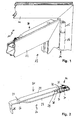
- FIG. 1 shows an upper corner portion of a window 10 with a fixed frame 11 and a wing frame 12 of a wing 13.
- the wing 13 is pivotally connected to the fixed frame 11 via a hinge assembly 14, which is formed in the embodiment as a pivot bearing, wherein the hinge assembly 14 a wing-side band member 15 and a welt-side band member 16 includes.
- the wing-side band part 15 is with a wing attachment assembly 20, which will be described in more detail below, connected.
- the wing attachment assembly 20 is shown in a perspective view.
- the wing attachment assembly 20 includes a steel member 21 and a wing attachment bracket 22.
- the steel member 21 is integrally formed in the embodiment. It was made by punching out a sheet and then bending it. It comprises a guide section 23, which is guided in a drive rod channel of the wing 13. Furthermore, the steel part 21 comprises a Switzerlandfactteil 24, from which a fastening portion 25 is bent for fastening the wing-side hinge part 15.
- the free end 26 of the guide portion 23 is attached via a rivet 27 to the Werner 24.
- the steel part 21 is bent.
- the steel part 21 is engaged behind by a cylindrical nut 28.
- an adjusting screw 29 is screwed, which also extends through the wing mounting bracket 22.
- the wing mounting bracket 22 is bolted by means of fasteners 30,31 with the casement 12.
- the distance between the wing mounting bracket 22 and the steel part 21 can be changed.
- the steel part 21 abuts against a stop 32 of the wing mounting bracket 22.
- FIG. 3 is a plan view of the wing attachment assembly 21, in particular the Switzerlandfactteil 24 and the wing mounting bracket 22 shown.
- the stop 32 can be seen, to which the steel part 21 abuts.
- the stop 32 is connected via a predetermined breaking point with the remaining wing mounting bracket 22, in particular a mounting portion 33. This is in the enlarged detail of the FIG. 4 to recognize.
- the predetermined breaking point is provided with the reference numeral 35.
- the sash frame 12 is shown partially cut in order to better recognize the arrangement of the sash mounting arrangement 20 on the sash.
- the guide portion 23 is inserted into a drive rod channel 36.
- the wing attachment assembly 20 is already fixed in one of two dimensions and can only be moved in the wing circumferential direction.
- a determination in the wing circumferential direction is made by the wing mounting bracket 22, the mounting portion 33 is screwed to the sash 12.
- the adjusting screw 29 By adjusting the adjusting screw 29, the position of the wing-side hinge part 15 with respect to the wing 13 and the wing frame 12 can be changed. As a result, the distance of the wing 13 is changed to the fixed enclosure 11.
- FIG. 6 shows a sectional view along the line VI - VI of FIG. 5 , Here it can be seen that the guide section 23 is guided in the drive rod channel 36 and is overlapped by legs 37, 38 of the cross-sectionally C-shaped drive rod channel 36.
- the Switzerlandteil 24 is disposed above the drive rod channel 26.
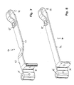
- FIG. 7 an embodiment of a steel part 50 is shown, in which a fastening portion 51 for attaching the wing-side hinge part 15 connects to the guide portion 52 materially. Between the actual guide portion 52 and the mounting portion 51, a step-like increase 53 is provided. At its wing mounting bracket side End 54, the steel part 50 is bent and fixed with its free end 55 to the guide portion 52, in particular riveted to this.
- the embodiment according to the FIG. 8 essentially corresponds to the FIG. 7 with the difference that the guide section 52 is completely straight and no step 53 as in FIG. 7 followed. Also in this embodiment, the attachment portion 51 is materially connected to the guide portion 52. In the FIG. 8 the steel part is provided with the reference numeral 60.
Landscapes
- Engineering & Computer Science (AREA)
- Mechanical Engineering (AREA)
- Hinges (AREA)
- Securing Of Glass Panes Or The Like (AREA)
Abstract
Description
- Die Erfindung betrifft eine Flügelbefestigungsanordnung eines Dreh- oder Dreh-Kipp-Lagers für ein Fenster, eine Tür oder dgl.
- Zur dreh- und/oder kippbaren Befestigung eines Flügels an einer festen Einfassung ist es bekannt, ein entsprechendes Lager zu verwenden. Ein derartiges Lager weist daher eine einfassungsseitige und eine flügelseitige Befestigungsanordnung auf. Bislang wurden derartige Befestigungsanordnungen nahezu ausschließlich als Zink - Druck-Gussteile hergestellt. Wegen des steigenden Rohstoffpreises von Zink ist es jedoch erforderlich, nach neuen Befestigungsmöglichkeiten zu suchen.
- Aufgabe der vorliegenden Erfindung ist es daher, eine Flügelbefestigungsanordnung bereitzustellen, welche wenige Teile aufweist und die kostengünstig herstellbar ist.
- Gelöst wird diese Aufgabe erfindungsgemäß auf einfache und überraschende Art und Weise durch eine Flügelbefestigungsanordnung eines Dreh- oder Dreh-Kipp-Lagers für ein Fenster, eine Tür oder dgl. mit einem Stahlteil, welches einen Führungsabschnitt zur Führung des Stahlteils in einem Treibstangenkanal eines Flügels aufweist, und einem Flügelbefestigungsbock, der mit dem Stahlteil verbunden ist. Eine derartige Flügelbefestigungsanordnung ist sehr robust bei einem gleichzeitig sehr einfachen technischen Aufbau. Dadurch, dass das Stahlteil einen Führungsabschnitt aufweist, der in einem Treibstangenkanal des Flügels geführt ist, ist die Flügelbefestigungsanordnung bereits in einer Dimension am Flügel festgelegt und bedarf keiner weiteren zusätzlichen Befestigungsmöglichkeit. Der Führungsabschnitt ist dabei vorzugsweise so ausgestaltet, dass er eine ausreichende Breite aufweist, um an zwei gegenüberliegenden Seiten von dem hinterschnittenen Treibstangenkanal übergriffen zu werden. Die Verwendung von Stahl hat den Vorteil, dass der Beschlag dadurch zum einen sehr stabil ausgebildet werden kann und zum anderen, dass der Stahl einfach und kostengünstig bearbeitbar ist, bei einem geringen Rohstoffpreis.
- Besonders kostengünstig lässt sich das Stahlteil herstellen, wenn es als Stanz-Biegeteil oder lasergeschnittenes Biegeteil ausgebildet ist. Insbesondere ist das Stahlteil vorzugsweise einstückig aus einem Blech ausgestanzt oder ausgeschnitten und anschließend in die erforderliche Form gebogen.
- Besondere Vorteile ergeben sich, wenn das Stahlteil einen abschnittsweise parallel zum Führungsabschnitt verlaufenden Zugaufnahmeteil aufweist. Dadurch können durch das Flügelgewicht bewirkte Zugkräfte besonders gut aufgenommen werden. Die Stabilität der Flügelbefestigungsanordnung wird erhöht.
- Gemäß einer bevorzugten Weiterbildung kann vorgesehen sein, dass das freie Ende des Führungsabschnitts mit dem Zugaufnahmeteil verbunden ist. Dadurch erfolgt eine weitere Aussteifung der Flügelbefestigungsanordnung. Insbesondere kann der Führungsabschnitt mit dem Zugaufnahmeteil durch einen Niet oder einen Schweißpunkt verbunden sein. Weiterhin ist es denkbar, dass das Zugaufnahmeteil eine Öffnung aufweist, in die eine Lasche des Führungsabschnitts eingehängt ist.
- Bei einer besonders bevorzugten Ausführungsform kann vorgesehen sein, dass der Flügelbefestigungsbock mit dem Stahlteil über eine Stellschraube verbunden ist. Über die Stellschraube kann der Abstand zwischen Stahlteil und Flügelbefestigungsbock eingestellt werden. Dadurch lässt sich die Position des Flügels in Bezug zum festen Rahmen einstellen.
- Während es grundsätzlich denkbar ist, in dem Stahlteil ein Gewinde vorzusehen, in das die Stellschraube eingeschraubt ist, ist erfindungsgemäß vorteilhafterweise eine das Stahlteil abschnittsweise hintergreifende Mutter vorgesehen, in die die Stellschraube eingeschraubt ist. Dadurch kann der Bearbeitungsschritt des Gewindeschneidens in das Stahlteil vermieden werden. Die Mutter kann so dimensioniert werden, dass eine ausreichend große Anlagefläche der Mutter an dem Stahlteil existiert. Vorzugsweise ist die Mutter an der Stelle des Stahlteils angeordnet, wo das Stahlteil umgebogen ist und vom Zugaufnahmeteil in das Führungsteil übergeht. Das Stahlteil weist in diesem Bereich vorzugsweise eine Durchgangsöffnung auf, die die Stellschraube durchgreifen kann. Die Durchgangsöffnung kann bei der Herstellung des Stahlteils ausgestanzt oder mit einem Laser ausgeschnitten werden.
- Bei einer Ausgestaltung der Erfindung kann vorgesehen sein, dass der Flügelbefestigungsbock einen Anschlag für das Stahlteil aufweist. Durch diese Maßnahme kann das Stahlteil bei der Montage richtig positioniert werden, insbesondere in einer so genannten Nullstellung positioniert werden. Bei der Montage legt also der Anschlag die Position des Stahlteils fest.
- Weitere Vorteile ergeben sich, wenn der Anschlag über eine Sollbruchstelle mit dem Befestigungsabschnitt des Flügelbefestigungsbocks verbunden ist. Durch diese Maßnahme ist nach der Montage auch eine Verstellung des Stahlteils in Richtung Flügelbefestigungsbock möglich, wenn beispielsweise die Falzluft zwischen der festen Einfassung und dem Flügel verringert werden muss.
- Weitere Vorteile ergeben sich, wenn der Führungsabschnitt materialschlüssig mit dem Befestigungsabschnitt zur Befestigung des flügelseitigen Bandteils verbunden ist. Dadurch können der Führungsabschnitt und der Befestigungsabschnitt einstückig ausgebildet werden. Der Befestigungsabschnitt kann insbesondere durch Abbiegen oder Abkanten gegenüber dem Führungsabschnitt realisiert werden.
- Bei einer Ausgestaltung der Erfindung kann vorgesehen sein, dass das Stahlteil flügelbefestigungsbockseitig umgebogen ist und das freie Ende mit dem Führungsabschnitt verbunden ist. Dabei kann das freie Ende beispielsweise mit dem Führungsabschnitt vernietet sein.
- In den Rahmen der Erfindung fällt außerdem ein Drehlager oder ein Dreh-Kipp-Lager mit einer oben beschriebenen Flügelbefestigungsanordnung.
- Außerdem fällt in den Rahmen der Erfindung ein Fenster, eine Tür oder dgl. mit einer oben beschriebenen Flügelbefestigungsanordnung.
- Weitere Merkmale und Vorteile der Erfindung ergeben sich aus der nachfolgenden Beschreibung von Ausführungsbeispielen der Erfindung, anhand der Figuren der Zeichnung, die erfindungswesentliche Einzelheiten zeigen, und aus den Ansprüchen. Die einzelnen Merkmale können je einzeln für sich oder zu mehreren in beliebiger Kombination bei einer Variante der Erfindung verwirklicht sein.
- Bevorzugte Ausführungsbeispiele der Erfindung sind in der Zeichnung schematisch dargestellt und werden nachfolgend mit Bezug zu den Figuren der Zeichnung näher erläutert. Es zeigt:
- Fig. 1
- den oberen Eckbereich eines Fensters in einer perspektivischen Darstellung;
- Fig. 2
- eine perspektivische Ansicht einer erfindungsgemäßen Flügel- befestigungsanordnung;
- Fig. 3
- einer Draufsicht auf die erfindungsgemäße Flügelbefestigungs- anordnung;
- Fig. 4
- ein Detail der Flügelbefestigungsanordnung im Bereich einer Sollbruchstelle;
- Fig. 5
- eine teilweise geschnittene Darstellung eines Abschnitts eines Flügels, in dem die Flügelbefestigungsanordnung montiert ist; und
- Fig. 6
- eine Schnittdarstellung gemäß der Linie VI - VI der
Fig. 5 . - Fig. 7
- eine perspektivische Darstellung einer weiteren Ausführungs- form eines Stahlteils; und
- Fig. 8
- eine weitere Ausführungsform eines Stahlteils in perspektivi- scher Darstellung.
- Die
Figur 1 zeigt einen oberen Eckbereich eines Fensters 10 mit einem festen Rahmen 11 und einem Flügelrahmen 12 eines Flügels 13. Der Flügel 13 ist mit dem festen Rahmen 11 schwenkbar über eine Scharnieranordnung 14, welche im Ausführungsbeispiel als Drehlager ausgebildet ist, verbunden, wobei die Scharnieranordnung 14 ein flügelseitiges Bandteil 15 und ein einfassungsseitiges Bandteil 16 umfasst. Das flügelseitige Bandteil 15 ist mit einer Flügelbefestigungsanordnung 20, die im Folgenden näher beschrieben wird, verbunden. - In der
Figur 2 ist die Flügelbefestigungsanordnung 20 in einer perspektivischen Ansicht gezeigt. Die Flügelbefestigungsanordnung 20 umfasst ein Stahlteil 21 und einen Flügelbefestigungsbock 22. Das Stahlteil 21 ist im Ausführungsbeispiel einstückig ausgebildet. Es wurde durch Ausstanzen aus einem Blech und anschließendem Biegen hergestellt. Es umfasst einen Führungsabschnitt 23, der in einem Treibstangenkanal des Flügels 13 geführt ist. Weiterhin umfasst das Stahlteil 21 ein Zugaufnahmeteil 24, von dem ein Befestigungsabschnitt 25 zur Befestigung des flügelseitigen Bandteils 15 abgebogen ist. - Das freie Ende 26 des Führungsabschnitts 23 ist über einen Niet 27 an dem Zugaufnahmeteil 24 befestigt. Im Übergangsbereich 27 zwischen dem Führungsabschnitt 23 und dem Zugaufnahmeteil 24 ist das Stahlteil 21 umgebogen. An dieser Stelle ist das Stahlteil 21 von einer zylindrisch ausgebildeten Mutter 28 hintergriffen. In die Mutter 28 ist eine Stellschraube 29 eingeschraubt, die auch den Flügelbefestigungsbock 22 durchragt. Der Flügelbefestigungsbock 22 ist mittels Befestigungsmitteln 30,31 mit dem Flügelrahmen 12 verschraubt. Über die Stellschraube 29 kann der Abstand zwischen den Flügelbefestigungsbock 22 und dem Stahlteil 21 verändert werden. In einer Montagestellung schlägt das Stahlteil 21 an einen Anschlag 32 des Flügelbefestigungsbocks 22 an.
- In der
Figur 3 ist eine Draufsicht auf die Flügelbefestigungsanordnung 21, insbesondere das Zugaufnahmeteil 24 und den Flügelbefestigungsbock 22, gezeigt. Hier ist der Anschlag 32 zu erkennen, an den das Stahlteil 21 anschlägt. Um eine Verstellung des Stahlteils 21 in Richtung des Flügelbefestigungsbocks 22 zu ermöglichen, indem die Stellschraube 29 weiter in die Mutter 28 eingedreht wird, ist der Anschlag 32 über eine Sollbruchstelle mit dem übrigen Flügelbefestigungsbock 22, insbesondere einem Befestigungsabschnitt 33, verbunden. Dies ist in der vergrößerten Detaildarstellung derFigur 4 zu erkennen. Die Sollbruchstelle ist mit der Bezugsziffer 35 versehen. - In der
Figur 5 ist der Flügelrahmen 12 teilweise geschnitten dargestellt, um die Anordnung der Flügelbefestigungsanordnung 20 am Flügelrahmen besser erkennen zu können. Der Führungsabschnitt 23 ist in einen Treibstangenkanal 36 eingeschoben. Dadurch ist die Flügelbefestigungsanordnung 20 in einer von zwei Dimensionen bereits festgelegt und lässt sich nur noch in Flügelumfangsrichtung bewegen. Eine Festlegung in Flügelumfangsrichtung erfolgt durch den Flügelbefestigungsbock 22, dessen Befestigungsabschnitt 33 mit dem Flügelrahmen 12 verschraubt ist. Durch Verstellen der Stellschraube 29 kann die Position des flügelseitigen Bandteils 15 bezüglich des Flügels 13 beziehungsweise des Flügelrahmens 12 verändert werden. Dadurch wird auch der Abstand des Flügels 13 zur festen Einfassung 11 verändert. - Die
Figur 6 zeigt eine Schnittdarstellung gemäß der Linie VI - VI derFigur 5 . Hier ist zu erkennen, dass der Führungsabschnitt 23 in dem Treibstangenkanal 36 geführt ist und von Schenkeln 37,38 des im Querschnitt c-förmigen Treibstangenkanals 36 übergriffen ist. Das Zugaufnahmeteil 24 ist über dem Treibstangenkanal 26 angeordnet. - In der
Figur 7 ist eine Ausgestaltung eines Stahlteils 50 gezeigt, bei dem sich ein Befestigungsabschnitt 51 zur Befestigung des flügelseitigen Bandteils 15 an den Führungsabschnitt 52 materialschlüssig anschließt. Zwischen dem eigentlichen Führungsabschnitt 52 und dem Befestigungsabschnitt 51 ist eine stufenartige Erhöhung 53 vorgesehen. An seinem flügelbefestigungsbockseitigen Ende 54 ist das Stahlteil 50 umgebogen und mit seinem freien Ende 55 an dem Führungsabschnitt 52 befestigt, insbesondere mit diesem vernietet. - Die Ausführungsform gemäß der
Figur 8 entspricht im Wesentlichen derFigur 7 mit dem Unterschied, dass der Führungsabschnitt 52 vollständig gerade ist und sich keine Stufe 53 wie in derFigur 7 anschließt. Auch bei dieser Ausführungsform ist der Befestigungsabschnitt 51 materialschlüssig mit dem Führungsabschnitt 52 verbunden. In derFigur 8 ist das Stahlteil mit der Bezugsziffer 60 versehen.
Claims (12)
- Flügelbefestigungsanordnung (20) eines Dreh- oder Dreh-Kipp-Lagers für ein Fenster (10), eine Tür oder dgl. mit einem Stahlteil (21,50,60), welches einen Führungsabschnitt (23,52) zur Führung des Stahlteils (21,50,60) in einem Treibstangenkanal (36) eines Flügels (13) aufweist, und einem Flügelbefestigungsbock (22), der mit dem Stahlteil (21,50,60) verbunden ist.
- Flügelbefestigungsanordnung nach Anspruch 1, dadurch gekennzeichnet, dass das Stahlteil (21,50,60) als Stanz-Biegeteil oder lasergeschnittenes Biegeteil ausgebildet ist.
- Flügelbefestigungsanordnung nach einem der vorhergehenden Ansprüche, dadurch gekennzeichnet, dass das Stahlteil (21) einen abschnittsweise parallel zum Führungsabschnitt (23) verlaufenden Zugaufnahmeteil (24) aufweist.
- Flügelbefestigungsanordnung nach Anspruch 3, dadurch gekennzeichnet, dass das freie Ende (26) des Führungsabschnitts (23) mit dem Zugaufnahmeteil (24) verbunden ist.
- Flügelbefestigungsanordnung nach einem der vorhergehenden Ansprüche, dadurch gekennzeichnet, dass der Flügelbefestigungsbock (22) mit dem Stahlteil (21,50,60) über eine Stellschraube (29) verbunden ist.
- Flügelbefestigungsanordnung nach Anspruch 5, dadurch gekennzeichnet, dass eine das Stahlteil (21,50,60) abschnittsweise hintergreifende Mutter (28) vorgesehen ist, in die die Stellschraube (29) eingeschraubt ist.
- Flügelbefestigungsanordnung nach einem der vorhergehenden Ansprüche, dadurch gekennzeichnet, dass der Flügelbefestigungsbock (22) einen Anschlag (32) für das Stahlteil (21,50,60) aufweist.
- Flügelbefestigungsanordnung nach Anspruch 7, dadurch gekennzeichnet, dass der Anschlag (32) über eine Sollbruchstelle (35) mit dem Befestigungsabschnitt (33) des Flügelbefestigungsbocks (22) verbunden ist.
- Flügelbefestigungsanordnung nach einem der vorgehenden Ansprüche, dadurch gekennzeichnet, dass der Führungsabschnitt (52) materialschlüssig mit einem Befestigungsabschnitt (51) zur Befestigung des flügelseitigen Bandteils (15) verbunden ist.
- Flügelbefestigungsanordnung nach einem der vorgehenden Ansprüche, dadurch gekennzeichnet, dass das Stahlteil flügelbefestigungsbockseitig umgebogen ist und das freie Ende (55) mit dem Führungsabschnitt (52) verbunden ist.
- Drehlager oder Dreh-Kipp-Lager mit einer Flügelbefestigungsanordnung (20) nach einem der vorhergehenden Ansprüche.
- Fenster (10), Tür oder dgl. mit einer Flügelbefestigungsanordnung (20) nach einem der vorhergehenden Ansprüche 1 - 10.
Priority Applications (4)
| Application Number | Priority Date | Filing Date | Title |
|---|---|---|---|
| PL07019588T PL2045426T3 (pl) | 2007-10-06 | 2007-10-06 | Zestaw przyłączeniowy skrzydła łożyska obrotowego |
| ES07019588.8T ES2464594T3 (es) | 2007-10-06 | 2007-10-06 | Dispositivo de fijación de un cojinete oscilante para una hoja de ventana |
| EP07019588.8A EP2045426B1 (de) | 2007-10-06 | 2007-10-06 | Flügelbefestigungsanordnung eines Drehlagers |
| CN2008101689548A CN101403267B (zh) | 2007-10-06 | 2008-10-06 | 旋转支承的翼扇固定装置、旋转支承装置和相应的窗或门 |
Applications Claiming Priority (1)
| Application Number | Priority Date | Filing Date | Title |
|---|---|---|---|
| EP07019588.8A EP2045426B1 (de) | 2007-10-06 | 2007-10-06 | Flügelbefestigungsanordnung eines Drehlagers |
Publications (2)
| Publication Number | Publication Date |
|---|---|
| EP2045426A1 true EP2045426A1 (de) | 2009-04-08 |
| EP2045426B1 EP2045426B1 (de) | 2014-02-26 |
Family
ID=39092340
Family Applications (1)
| Application Number | Title | Priority Date | Filing Date |
|---|---|---|---|
| EP07019588.8A Active EP2045426B1 (de) | 2007-10-06 | 2007-10-06 | Flügelbefestigungsanordnung eines Drehlagers |
Country Status (4)
| Country | Link |
|---|---|
| EP (1) | EP2045426B1 (de) |
| CN (1) | CN101403267B (de) |
| ES (1) | ES2464594T3 (de) |
| PL (1) | PL2045426T3 (de) |
Cited By (1)
| Publication number | Priority date | Publication date | Assignee | Title |
|---|---|---|---|---|
| EP3279418A1 (de) * | 2016-08-01 | 2018-02-07 | Wilh. Schlechtendahl & Söhne GmbH & Co. KG | Beschlagteil eines beschlages und verfahren zur montage eines derartigen beschlagteils |
Citations (4)
| Publication number | Priority date | Publication date | Assignee | Title |
|---|---|---|---|---|
| DE2064047A1 (de) | 1970-12-28 | 1972-07-13 | Keller, Eberhard, 7121 Freudental | Vorrichtung zur Feineinstellung von Dreh Kipp Fenstern |
| DE2746190A1 (de) | 1977-10-14 | 1979-04-19 | Ver Baubeschlag Gretsch Co | Ausstellvorrichtung |
| DE3702957C1 (de) | 1987-01-31 | 1988-05-11 | Siegenia Frank Kg | Scharnierbeschlag fuer Fenster,Tueren o.dgl. |
| DE29717177U1 (de) | 1997-09-25 | 1999-02-04 | Ferco International Ferrures et Serrures de Bâtiment S.A., Reding | Beschlag zur Drehlagerung eines Fenster- oder Türflügels |
-
2007
- 2007-10-06 PL PL07019588T patent/PL2045426T3/pl unknown
- 2007-10-06 EP EP07019588.8A patent/EP2045426B1/de active Active
- 2007-10-06 ES ES07019588.8T patent/ES2464594T3/es active Active
-
2008
- 2008-10-06 CN CN2008101689548A patent/CN101403267B/zh active Active
Patent Citations (4)
| Publication number | Priority date | Publication date | Assignee | Title |
|---|---|---|---|---|
| DE2064047A1 (de) | 1970-12-28 | 1972-07-13 | Keller, Eberhard, 7121 Freudental | Vorrichtung zur Feineinstellung von Dreh Kipp Fenstern |
| DE2746190A1 (de) | 1977-10-14 | 1979-04-19 | Ver Baubeschlag Gretsch Co | Ausstellvorrichtung |
| DE3702957C1 (de) | 1987-01-31 | 1988-05-11 | Siegenia Frank Kg | Scharnierbeschlag fuer Fenster,Tueren o.dgl. |
| DE29717177U1 (de) | 1997-09-25 | 1999-02-04 | Ferco International Ferrures et Serrures de Bâtiment S.A., Reding | Beschlag zur Drehlagerung eines Fenster- oder Türflügels |
Cited By (1)
| Publication number | Priority date | Publication date | Assignee | Title |
|---|---|---|---|---|
| EP3279418A1 (de) * | 2016-08-01 | 2018-02-07 | Wilh. Schlechtendahl & Söhne GmbH & Co. KG | Beschlagteil eines beschlages und verfahren zur montage eines derartigen beschlagteils |
Also Published As
| Publication number | Publication date |
|---|---|
| CN101403267B (zh) | 2013-03-06 |
| ES2464594T3 (es) | 2014-06-03 |
| PL2045426T3 (pl) | 2014-08-29 |
| EP2045426B1 (de) | 2014-02-26 |
| CN101403267A (zh) | 2009-04-08 |
Similar Documents
| Publication | Publication Date | Title |
|---|---|---|
| EP2246509B1 (de) | Verschiebevorrichtung für drehbar gehaltene Trennelemente und Möbelstück | |
| DE3872442T2 (de) | Drehbeschlag eines drehkippfluegels einer tuer eines fensters oder von aehnlichem. | |
| DE3822050A1 (de) | Tuergriffanordnung an einer fahrzeugtuer | |
| EP3060736B1 (de) | Beschlag für fenster, türen oder dergleichen | |
| EP0294630A2 (de) | Verriegelungsbeschlag für Fenster, Türen od.dgl. | |
| EP1788178B1 (de) | Lager für Fenster, Türen oder dergleichen | |
| DE4313610A1 (de) | Ausstellvorrichtung für einen Dreh-Kipp-Flügel | |
| EP1936086B1 (de) | Ecklagerbeschlag für Fenster, Türen oder dgl. | |
| EP2013045B1 (de) | Hubfenster | |
| EP2045426B1 (de) | Flügelbefestigungsanordnung eines Drehlagers | |
| EP3279418B1 (de) | Beschlagteil eines beschlages und verfahren zur montage eines derartigen beschlagteils | |
| EP1915498B1 (de) | Profilbandsystem | |
| DE2805465C2 (de) | Treibstangenbeschlag | |
| EP2304145B1 (de) | Kraftfahrzeug mit einer heckklappe | |
| EP1746235B1 (de) | Beschlaganordnung | |
| DE10114384B4 (de) | Kraftfahrzeugtür | |
| DE202007017519U1 (de) | Beschlaganordnung | |
| EP3146134B1 (de) | Einstellbare vertikalaussteifung mit kulisse für einen abstellbaren flügel eines fensters oder einer tür | |
| EP0620344A1 (de) | Kupplungseinrichtung einer Schubstange oder eines Beschlagmitnehmers für eine in Nuten geführte Riegelstange eines Fensters oder einer Tür | |
| DE2064047A1 (de) | Vorrichtung zur Feineinstellung von Dreh Kipp Fenstern | |
| EP1788175A1 (de) | Laschenanordnung für Fenster, Türen oder dergleichen | |
| EP1936085B1 (de) | Beschlag für Fenster, Türen oder dgl. | |
| EP3543444B1 (de) | Lager für eine beschlaganordnung eines fensters | |
| DE102007051658B3 (de) | Drehlagerbock | |
| EP0258639B1 (de) | Bremsvorrichtung für einen Flügel eines Fensters, einer Tür od. dgl. |
Legal Events
| Date | Code | Title | Description |
|---|---|---|---|
| PUAI | Public reference made under article 153(3) epc to a published international application that has entered the european phase |
Free format text: ORIGINAL CODE: 0009012 |
|
| AK | Designated contracting states |
Kind code of ref document: A1 Designated state(s): AT BE BG CH CY CZ DE DK EE ES FI FR GB GR HU IE IS IT LI LT LU LV MC MT NL PL PT RO SE SI SK TR |
|
| AX | Request for extension of the european patent |
Extension state: AL BA HR MK RS |
|
| 17P | Request for examination filed |
Effective date: 20090924 |
|
| AKX | Designation fees paid |
Designated state(s): AT BE BG CH CY CZ DE DK EE ES FI FR GB GR HU IE IS IT LI LT LU LV MC MT NL PL PT RO SE SI SK TR |
|
| 17Q | First examination report despatched |
Effective date: 20100728 |
|
| GRAP | Despatch of communication of intention to grant a patent |
Free format text: ORIGINAL CODE: EPIDOSNIGR1 |
|
| INTG | Intention to grant announced |
Effective date: 20131002 |
|
| GRAS | Grant fee paid |
Free format text: ORIGINAL CODE: EPIDOSNIGR3 |
|
| GRAA | (expected) grant |
Free format text: ORIGINAL CODE: 0009210 |
|
| AK | Designated contracting states |
Kind code of ref document: B1 Designated state(s): AT BE BG CH CY CZ DE DK EE ES FI FR GB GR HU IE IS IT LI LT LU LV MC MT NL PL PT RO SE SI SK TR |
|
| REG | Reference to a national code |
Ref country code: GB Ref legal event code: FG4D Free format text: NOT ENGLISH |
|
| REG | Reference to a national code |
Ref country code: CH Ref legal event code: EP |
|
| REG | Reference to a national code |
Ref country code: AT Ref legal event code: REF Ref document number: 653727 Country of ref document: AT Kind code of ref document: T Effective date: 20140315 |
|
| REG | Reference to a national code |
Ref country code: IE Ref legal event code: FG4D Free format text: LANGUAGE OF EP DOCUMENT: GERMAN |
|
| REG | Reference to a national code |
Ref country code: DE Ref legal event code: R096 Ref document number: 502007012780 Country of ref document: DE Effective date: 20140410 |
|
| REG | Reference to a national code |
Ref country code: ES Ref legal event code: FG2A Ref document number: 2464594 Country of ref document: ES Kind code of ref document: T3 Effective date: 20140603 |
|
| REG | Reference to a national code |
Ref country code: NL Ref legal event code: VDEP Effective date: 20140226 |
|
| REG | Reference to a national code |
Ref country code: LT Ref legal event code: MG4D |
|
| PG25 | Lapsed in a contracting state [announced via postgrant information from national office to epo] |
Ref country code: IS Free format text: LAPSE BECAUSE OF FAILURE TO SUBMIT A TRANSLATION OF THE DESCRIPTION OR TO PAY THE FEE WITHIN THE PRESCRIBED TIME-LIMIT Effective date: 20140626 Ref country code: LT Free format text: LAPSE BECAUSE OF FAILURE TO SUBMIT A TRANSLATION OF THE DESCRIPTION OR TO PAY THE FEE WITHIN THE PRESCRIBED TIME-LIMIT Effective date: 20140226 |
|
| PG25 | Lapsed in a contracting state [announced via postgrant information from national office to epo] |
Ref country code: FI Free format text: LAPSE BECAUSE OF FAILURE TO SUBMIT A TRANSLATION OF THE DESCRIPTION OR TO PAY THE FEE WITHIN THE PRESCRIBED TIME-LIMIT Effective date: 20140226 Ref country code: CY Free format text: LAPSE BECAUSE OF FAILURE TO SUBMIT A TRANSLATION OF THE DESCRIPTION OR TO PAY THE FEE WITHIN THE PRESCRIBED TIME-LIMIT Effective date: 20140226 Ref country code: SE Free format text: LAPSE BECAUSE OF FAILURE TO SUBMIT A TRANSLATION OF THE DESCRIPTION OR TO PAY THE FEE WITHIN THE PRESCRIBED TIME-LIMIT Effective date: 20140226 Ref country code: PT Free format text: LAPSE BECAUSE OF FAILURE TO SUBMIT A TRANSLATION OF THE DESCRIPTION OR TO PAY THE FEE WITHIN THE PRESCRIBED TIME-LIMIT Effective date: 20140626 Ref country code: NL Free format text: LAPSE BECAUSE OF FAILURE TO SUBMIT A TRANSLATION OF THE DESCRIPTION OR TO PAY THE FEE WITHIN THE PRESCRIBED TIME-LIMIT Effective date: 20140226 |
|
| REG | Reference to a national code |
Ref country code: PL Ref legal event code: T3 |
|
| PG25 | Lapsed in a contracting state [announced via postgrant information from national office to epo] |
Ref country code: LV Free format text: LAPSE BECAUSE OF FAILURE TO SUBMIT A TRANSLATION OF THE DESCRIPTION OR TO PAY THE FEE WITHIN THE PRESCRIBED TIME-LIMIT Effective date: 20140226 |
|
| PG25 | Lapsed in a contracting state [announced via postgrant information from national office to epo] |
Ref country code: EE Free format text: LAPSE BECAUSE OF FAILURE TO SUBMIT A TRANSLATION OF THE DESCRIPTION OR TO PAY THE FEE WITHIN THE PRESCRIBED TIME-LIMIT Effective date: 20140226 Ref country code: DK Free format text: LAPSE BECAUSE OF FAILURE TO SUBMIT A TRANSLATION OF THE DESCRIPTION OR TO PAY THE FEE WITHIN THE PRESCRIBED TIME-LIMIT Effective date: 20140226 Ref country code: RO Free format text: LAPSE BECAUSE OF FAILURE TO SUBMIT A TRANSLATION OF THE DESCRIPTION OR TO PAY THE FEE WITHIN THE PRESCRIBED TIME-LIMIT Effective date: 20140226 Ref country code: CZ Free format text: LAPSE BECAUSE OF FAILURE TO SUBMIT A TRANSLATION OF THE DESCRIPTION OR TO PAY THE FEE WITHIN THE PRESCRIBED TIME-LIMIT Effective date: 20140226 |
|
| REG | Reference to a national code |
Ref country code: DE Ref legal event code: R097 Ref document number: 502007012780 Country of ref document: DE |
|
| PG25 | Lapsed in a contracting state [announced via postgrant information from national office to epo] |
Ref country code: SK Free format text: LAPSE BECAUSE OF FAILURE TO SUBMIT A TRANSLATION OF THE DESCRIPTION OR TO PAY THE FEE WITHIN THE PRESCRIBED TIME-LIMIT Effective date: 20140226 |
|
| PLBE | No opposition filed within time limit |
Free format text: ORIGINAL CODE: 0009261 |
|
| STAA | Information on the status of an ep patent application or granted ep patent |
Free format text: STATUS: NO OPPOSITION FILED WITHIN TIME LIMIT |
|
| 26N | No opposition filed |
Effective date: 20141127 |
|
| REG | Reference to a national code |
Ref country code: DE Ref legal event code: R097 Ref document number: 502007012780 Country of ref document: DE Effective date: 20141127 |
|
| PG25 | Lapsed in a contracting state [announced via postgrant information from national office to epo] |
Ref country code: MC Free format text: LAPSE BECAUSE OF FAILURE TO SUBMIT A TRANSLATION OF THE DESCRIPTION OR TO PAY THE FEE WITHIN THE PRESCRIBED TIME-LIMIT Effective date: 20140226 Ref country code: LU Free format text: LAPSE BECAUSE OF FAILURE TO SUBMIT A TRANSLATION OF THE DESCRIPTION OR TO PAY THE FEE WITHIN THE PRESCRIBED TIME-LIMIT Effective date: 20141006 Ref country code: SI Free format text: LAPSE BECAUSE OF FAILURE TO SUBMIT A TRANSLATION OF THE DESCRIPTION OR TO PAY THE FEE WITHIN THE PRESCRIBED TIME-LIMIT Effective date: 20140226 |
|
| REG | Reference to a national code |
Ref country code: CH Ref legal event code: PL |
|
| GBPC | Gb: european patent ceased through non-payment of renewal fee |
Effective date: 20141006 |
|
| REG | Reference to a national code |
Ref country code: IE Ref legal event code: MM4A |
|
| PG25 | Lapsed in a contracting state [announced via postgrant information from national office to epo] |
Ref country code: GB Free format text: LAPSE BECAUSE OF NON-PAYMENT OF DUE FEES Effective date: 20141006 Ref country code: LI Free format text: LAPSE BECAUSE OF NON-PAYMENT OF DUE FEES Effective date: 20141031 Ref country code: CH Free format text: LAPSE BECAUSE OF NON-PAYMENT OF DUE FEES Effective date: 20141031 |
|
| REG | Reference to a national code |
Ref country code: FR Ref legal event code: PLFP Year of fee payment: 9 |
|
| PG25 | Lapsed in a contracting state [announced via postgrant information from national office to epo] |
Ref country code: IE Free format text: LAPSE BECAUSE OF NON-PAYMENT OF DUE FEES Effective date: 20141006 |
|
| PG25 | Lapsed in a contracting state [announced via postgrant information from national office to epo] |
Ref country code: BG Free format text: LAPSE BECAUSE OF FAILURE TO SUBMIT A TRANSLATION OF THE DESCRIPTION OR TO PAY THE FEE WITHIN THE PRESCRIBED TIME-LIMIT Effective date: 20140226 |
|
| PG25 | Lapsed in a contracting state [announced via postgrant information from national office to epo] |
Ref country code: GR Free format text: LAPSE BECAUSE OF FAILURE TO SUBMIT A TRANSLATION OF THE DESCRIPTION OR TO PAY THE FEE WITHIN THE PRESCRIBED TIME-LIMIT Effective date: 20140527 |
|
| PG25 | Lapsed in a contracting state [announced via postgrant information from national office to epo] |
Ref country code: HU Free format text: LAPSE BECAUSE OF FAILURE TO SUBMIT A TRANSLATION OF THE DESCRIPTION OR TO PAY THE FEE WITHIN THE PRESCRIBED TIME-LIMIT; INVALID AB INITIO Effective date: 20071006 Ref country code: MT Free format text: LAPSE BECAUSE OF FAILURE TO SUBMIT A TRANSLATION OF THE DESCRIPTION OR TO PAY THE FEE WITHIN THE PRESCRIBED TIME-LIMIT Effective date: 20140226 |
|
| REG | Reference to a national code |
Ref country code: FR Ref legal event code: PLFP Year of fee payment: 10 |
|
| REG | Reference to a national code |
Ref country code: FR Ref legal event code: PLFP Year of fee payment: 11 |
|
| REG | Reference to a national code |
Ref country code: FR Ref legal event code: PLFP Year of fee payment: 12 |
|
| PGFP | Annual fee paid to national office [announced via postgrant information from national office to epo] |
Ref country code: FI Payment date: 20181121 Year of fee payment: 15 |
|
| PGFP | Annual fee paid to national office [announced via postgrant information from national office to epo] |
Ref country code: FR Payment date: 20191022 Year of fee payment: 13 |
|
| REG | Reference to a national code |
Ref country code: AT Ref legal event code: MM01 Ref document number: 653727 Country of ref document: AT Kind code of ref document: T Effective date: 20191006 |
|
| PG25 | Lapsed in a contracting state [announced via postgrant information from national office to epo] |
Ref country code: AT Free format text: LAPSE BECAUSE OF NON-PAYMENT OF DUE FEES Effective date: 20191006 |
|
| PG25 | Lapsed in a contracting state [announced via postgrant information from national office to epo] |
Ref country code: FR Free format text: LAPSE BECAUSE OF NON-PAYMENT OF DUE FEES Effective date: 20201031 |
|
| PGFP | Annual fee paid to national office [announced via postgrant information from national office to epo] |
Ref country code: TR Payment date: 20250929 Year of fee payment: 19 Ref country code: PL Payment date: 20250924 Year of fee payment: 19 |
|
| PGFP | Annual fee paid to national office [announced via postgrant information from national office to epo] |
Ref country code: DE Payment date: 20251020 Year of fee payment: 19 |
|
| PGFP | Annual fee paid to national office [announced via postgrant information from national office to epo] |
Ref country code: IT Payment date: 20251031 Year of fee payment: 19 |
|
| PGFP | Annual fee paid to national office [announced via postgrant information from national office to epo] |
Ref country code: BE Payment date: 20251022 Year of fee payment: 19 |
|
| PGFP | Annual fee paid to national office [announced via postgrant information from national office to epo] |
Ref country code: ES Payment date: 20251114 Year of fee payment: 19 |