EP2044330B1 - Rotorpumpe - Google Patents
Rotorpumpe Download PDFInfo
- Publication number
- EP2044330B1 EP2044330B1 EP07764645A EP07764645A EP2044330B1 EP 2044330 B1 EP2044330 B1 EP 2044330B1 EP 07764645 A EP07764645 A EP 07764645A EP 07764645 A EP07764645 A EP 07764645A EP 2044330 B1 EP2044330 B1 EP 2044330B1
- Authority
- EP
- European Patent Office
- Prior art keywords
- rotor
- seal
- pump according
- sealing
- vane
- Prior art date
- Legal status (The legal status is an assumption and is not a legal conclusion. Google has not performed a legal analysis and makes no representation as to the accuracy of the status listed.)
- Active
Links
Images

Classifications
-
- F—MECHANICAL ENGINEERING; LIGHTING; HEATING; WEAPONS; BLASTING
- F04—POSITIVE - DISPLACEMENT MACHINES FOR LIQUIDS; PUMPS FOR LIQUIDS OR ELASTIC FLUIDS
- F04C—ROTARY-PISTON, OR OSCILLATING-PISTON, POSITIVE-DISPLACEMENT MACHINES FOR LIQUIDS; ROTARY-PISTON, OR OSCILLATING-PISTON, POSITIVE-DISPLACEMENT PUMPS
- F04C27/00—Sealing arrangements in rotary-piston pumps specially adapted for elastic fluids
- F04C27/001—Radial sealings for working fluid
-
- F—MECHANICAL ENGINEERING; LIGHTING; HEATING; WEAPONS; BLASTING
- F04—POSITIVE - DISPLACEMENT MACHINES FOR LIQUIDS; PUMPS FOR LIQUIDS OR ELASTIC FLUIDS
- F04C—ROTARY-PISTON, OR OSCILLATING-PISTON, POSITIVE-DISPLACEMENT MACHINES FOR LIQUIDS; ROTARY-PISTON, OR OSCILLATING-PISTON, POSITIVE-DISPLACEMENT PUMPS
- F04C18/00—Rotary-piston pumps specially adapted for elastic fluids
- F04C18/30—Rotary-piston pumps specially adapted for elastic fluids having the characteristics covered by two or more of groups F04C18/02, F04C18/08, F04C18/22, F04C18/24, F04C18/48, or having the characteristics covered by one of these groups together with some other type of movement between co-operating members
- F04C18/34—Rotary-piston pumps specially adapted for elastic fluids having the characteristics covered by two or more of groups F04C18/02, F04C18/08, F04C18/22, F04C18/24, F04C18/48, or having the characteristics covered by one of these groups together with some other type of movement between co-operating members having the movement defined in group F04C18/08 or F04C18/22 and relative reciprocation between the co-operating members
- F04C18/344—Rotary-piston pumps specially adapted for elastic fluids having the characteristics covered by two or more of groups F04C18/02, F04C18/08, F04C18/22, F04C18/24, F04C18/48, or having the characteristics covered by one of these groups together with some other type of movement between co-operating members having the movement defined in group F04C18/08 or F04C18/22 and relative reciprocation between the co-operating members with vanes reciprocating with respect to the inner member
- F04C18/3441—Rotary-piston pumps specially adapted for elastic fluids having the characteristics covered by two or more of groups F04C18/02, F04C18/08, F04C18/22, F04C18/24, F04C18/48, or having the characteristics covered by one of these groups together with some other type of movement between co-operating members having the movement defined in group F04C18/08 or F04C18/22 and relative reciprocation between the co-operating members with vanes reciprocating with respect to the inner member the inner and outer member being in contact along one line or continuous surface substantially parallel to the axis of rotation
Definitions
- the invention relates to a rotor pump with a pump housing, a rotor rotatably mounted in the pump housing and a rotor slidably mounted in the rotor, the wing tip abut an inner peripheral surface of the housing, wherein the rotor for slidably receiving the wing has a receiving slot which faces on the wing Side surface is provided with a seal which is formed by one or more sealing lips or sealing ribs.
- Rotor pumps are for example from the EP 1 471 255 B1 known. Such rotor pumps have the advantage that they have a low weight, since they are made substantially from plastic. However, these rotor pumps have the disadvantage that they dimensionally can not be made so accurate and precise that the desired tightness is achieved. Although deposits of ceramic or a hard plastic are provided on the flat sides of the wing, but hereby the tightness is not guaranteed.
- the GB-A-2 105 410 which is considered to be approaching the art, also shows a rotor pump with slidably guided wings, wherein the slots are provided with sealing edges.
- the guide surfaces of the slots are provided with a plurality of grooves.
- the invention is therefore based on the object to propose a rotor pump in which the wing sits tightly in the rotor.
- This object is achieved in that extending parallel to the sealing lips or sealing ribs extending channels behind the individual sealing lips or sealing ribs.
- the seal is formed by one or more sealing lips or sealing ribs.
- Such linear formations have the significant advantage that they rest only over a small area on the wing, whereby the frictional forces are greatly reduced, but the sealing forces are relatively high.
- a preferred embodiment provides that the sealing lips or sealing ribs extend parallel to the axis of rotation of the rotor. While other forms of seal are possible, seals extending parallel to the axis of rotation can be made relatively easily on both the rotor and the wing.
- sealing lips or sealing ribs form a labyrinth seal in which lubricating oil can be fed both for sealing and for lubrication purposes.
- the seal is located adjacent to the outer edge of the side surface of the receiving slot of the rotor, which is surmounted by the wing.
- the tilting tendency of the wing in the rotor is thereby prevented and the load on the seal is reduced to a minimum, since the length of the protruding from the rotor portion of the wing is immediately adjacent to the seal and thus the lever arm is reduced to the smallest degree.
- the seal is provided on the trailing in the direction of rotation of the rotor side on the rotor. This ensures that the wing rests permanently on the seal, so that the sealing effect is always maintained.
- the seal has a sealing tip, which is removed or displaced by the wing in the break-in phase. This creates the possibility that the receiving slot and the wing are made in a small excess and sets the optimum level in the break-in phase. As a result, tolerances are compensated, even with relatively inelastic seals.
- the seal may have a sealing tip which is rounded or angular.
- Angular tips have the advantage that they shrink relatively quickly, whereas rounded sealing tips offer a greater percentage of support. In particular, this plays a role when the seal is provided with fillers, such as lubricants and the like.
- the seal is an insert or provided on an insert. This variant offers the option of the seal made of special sealing materials manufacture, which are then inserted into the rotor.
- seal and the rotor are made of the same material, but also the material of the seal may be different from the material of the rotor.
- material of the seal may be different from the material of the rotor.
- these can be produced from the same material or else using the 2-component injection molding process.
- the material of the seal contains at least one additive that is solid, liquid or pasty.
- This can be, for example, graphite, Teflon (PTFE) or a plasticizer.
- a variant provides that the addition is harder than the material of the seal. As a result, the wear resistance of the seal is increased, whereas the elasticity can be adjusted by the shape of the seal, for example by a lamellar shape.
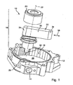
- FIG. 1 a total designed as a vacuum pump rotor pump, in which the housing 12 is shown without housing cover.
- the housing 12 has a suction port, which opens into an interior 16.
- this interior 16 is a generally designated 18 rotor in which a wing 20 is mounted orthogonal to the axis of rotation 22 slidably.
- the rotor 18 passes through the housing 12, in particular a bottom 26 of the interior 16 via a drive opening 28, so that it can be driven from the outside via a rectangular section 30.
- a receiving slot 24 which extends orthogonally to the axis of rotation 22 and has two side surfaces 32 on which between wing tips 34 located longitudinal sides 36 abut.
- the wing 20 performs an oscillatory movement in the direction of the double arrow 38.
- the opposing side surfaces 32 are each provided with a seal 42 which are provided on a trailing in the direction of rotation 40 section 44.
- the seal 42 is in the illustrated embodiment of three sealing ribs 46 (see FIG. 3 ), which extend parallel to the axis of rotation 22 of the rotor 18 and are immediately adjacent to the outer edge 48.
- the sealing ribs have, for example, a radius of 0.01 mm to 0.1 mm, in particular of 0.055 mm and a distance a from one another from 0.05 mm to 0.5 mm, in particular of 0.2 mm. For example, they are raised by 0.01 mm to 0.1 mm, in particular 0.05 mm, from the surface of the side surface 32.
- FIG. 3 stab behind the individual sealing ribs 46 parallel to the sealing ribs 46 extending channels 50, whereby the sealing ribs 46 experience a certain elasticity.
- lubricating oil can be performed, which exits in the interstices of the sealing ribs 46.
Landscapes
- Engineering & Computer Science (AREA)
- Mechanical Engineering (AREA)
- General Engineering & Computer Science (AREA)
- Applications Or Details Of Rotary Compressors (AREA)
Abstract
Description
- Die Erfindung betrifft eine Rotorpumpe mit einem Pumpengehäuse, einem im Pumpengehäuse drehbar gelagerten Rotor und einem im Rotor verschieblich gelagerten Flügel, dessen Flügelspitze an einer Innenumfangsfläche des Gehäuses anliegen, wobei der Rotor zur verschieblichen Aufnahme des Flügels einen Aufnahmeschlitz aufweist, der an der dem Flügel zugewandten Seitenfläche mit einer Dichtung versehen ist, die von einer oder mehreren Dichtlippen oder Dichtrippen gebildet wird.
- Rotorpumpen sind zum Beispiel aus der
EP 1 471 255 B1 bekannt. Derartige Rotorpumpen besitzen den Vorteil, dass sie ein geringes Gewicht aufweisen, da sie im Wesentlichen aus Kunststoff hergestellt sind. Diese Rotorpumpen besitzen jedoch den Nachteil, dass sie maßlich nicht so genau und präzise hergestellt werden können, dass die gewünschte Dichtheit erzielt wird. Zwar sind an den Flachseiten des Flügels Einlagen aus Keramik oder einem harten Kunststoff vorgesehen, jedoch wird hiermit die Dichtheit nicht gewährleistet. - Die
GB-A-2 105 410 JP-A-63189681 - Der Erfindung liegt daher die Aufgabe zugrunde, eine Rotorpumpe vorzuschlagen, bei welcher der Flügel dicht im Rotor sitzt.
- Diese Aufgabe wird erfindungsgemäß dadurch gelöst, dass sich hinter den einzelnen Dichtlippen oder Dichtrippen parallel zu den Dichtlippen oder Dichtrippen verlaufende Kanäle erstrecken.
- Bei der erfindungsgemäßen Rotorpumpe befindet sich also zwischen dem Flügel und wenigstens einer Seitenwand des den Flügel aufnehmenden Schlitzes des Rotors eine Dichtung, so dass über diese Dichtung Maßtoleranzen ausgeglichen werden können. Dies hat den wesentlichen Vorteil, dass nicht nur die herstellungsbedingten Maßtoleranzen, sondern auch temperaturbedingte Toleranzen eliminiert werden.
- Die Dichtung wird von einer oder mehreren Dichtlippen oder Dichtrippen gebildet. Derartige linienförmige Gebilde besitzen den wesentlichen Vorteil, dass sie nur über eine geringe Fläche am Flügel anliegen, wodurch die Reibungskräfte stark vermindert werden, jedoch die Abdichtkräfte relativ hoch sind.
- Eine bevorzugte Ausgestaltung sieht vor, dass sich die Dichtlippen oder Dichtrippen parallel zur Drehachse des Rotors erstrecken. Zwar sind andere Formen der Dichtung möglich, jedoch können sich parallel zur Drehachse erstreckende Dichtungen relativ einfach sowohl am Rotor als auch am Flügel hergestellt werden.
- Mit Vorzug bilden die Dichtlippen oder Dichtrippen eine Labyrinthdichtung, in welche sowohl zu Dicht- als auch zu Lubrikationszwecken Schmieröl eingespeist werden kann.
- Mit Vorzug befindet sich die Dichtung im Anschluss an die vom Flügel überragte Außenkante des der Seitenfläche des Aufnahmeschlitzes des Rotors. Die Kippneigung des Flügels im Rotor wird dadurch verhindert und die Belastung der Dichtung auf ein Minimum reduziert, da die Länge des aus dem Rotor herausragenden Abschnitts des Flügels sich unmittelbar an die Dichtung anschließt und somit der Hebelarm auf das geringste Maß reduziert ist.
- Bevorzugt ist die Dichtung auf der in Drehrichtung des Rotors nacheilenden Seite am Rotor vorgesehen. Hierdurch wird sichergestellt, dass der Flügel permanent an der Dichtung anliegt, so dass die Dichtwirkung stets aufrechterhalten bleibt.
- Bei einem Ausführungsbeispiel weist die Dichtung eine Dichtspitze auf, die vom Flügel in der Einlaufphase abgetragen oder verdrängt wird. Hierdurch wird die Möglichkeit geschaffen, dass der Aufnahmeschlitz und der Flügel in einem geringen Übermaß hergestellt werden und sich das optimale Maß in der Einlaufphase einstellt. Hierdurch werden Toleranzen ausgeglichen, auch bei relativ unelastischen Dichtungen.
- Dabei kann die Dichtung eine Dichtspitze aufweisen, die abgerundet oder eckig ist. Eckige Spitzen besitzen den Vorteil, dass sie relativ schnell einlaufen, wohingegen abgerundete Dichtspitzen einen größeren Traganteil bieten. Insbesondere spielt dies dann eine Rolle, wenn die Dichtung mit Füllstoffen versehen ist, wie Gleitmittel und dergleichen.
- Bei einer Weiterbildung ist die Dichtung ein Einsatz oder an einem Einsatz vorgesehen. Diese Variante bietet die Möglichkeit, die Dichtung aus speziellen Dichtungsmaterialien herzustellen, welche dann in den Rotor eingesetzt werden.
- Eine einfache Variante sieht vor, dass die Dichtung und der Rotor aus dem gleichen Material bestehen, wobei aber auch das Material der Dichtung vom Material des Rotors verschieden sein kann. Bei spritzgegossenen Bauteilen können diese aus dem gleichen Material oder auch im 2-K-Spritzgießverfahren hergestellt werden.
- Wie bereits erwähnt, enthält das Material der Dichtung wenigstens einen Zusatz, der fest, flüssig oder pastös ist. Dies kann zum Beispiel Graphit, Teflon (PTFE) oder ein Weichmacher sein.
- Eine Variante sieht vor, dass der Zusatz härter ist als das Material der Dichtung. Hierdurch wird die Verschleißfestigkeit der Dichtung erhöht, wohingegen die Elastizität durch die Form der Dichtung, zum Beispiel durch eine Lamellenform, eingestellt werden kann.
- Weitere Vorteile, Merkmale und Einzelheiten der Erfindung ergeben sich aus den Unteransprüchen sowie der nachfolgenden Beschreibung, in der unter Bezugnahme auf die Zeichnung zwei besonders bevorzugte Ausführungsbeispiele im Einzelnen beschrieben sind. Dabei können die in der Zeichnung dargestellten sowie die in der Beschreibung und in den Ansprüchen erwähnten Merkmale jeweils einzeln für sich oder in beliebiger Kombination erfindungswesentlich sein.
- In der Zeichnung zeigen:
- Figur 1
- eine Explosionsdarstellung einer Rotorpumpe;
- Figur 2
- einen Teil des Rotors mit eingesetztem Flügel;
- Figur 3
- eine vergrößerte Wiedergabe des linken, aus dem Rotor herausragenden Teils des Flügels.
- In der
Figur 1 ist mit dem Bezugszeichen 10 insgesamt eine als Vakuumpumpe ausgebildete Rotorpumpe bezeichnet, bei welcher das Gehäuse 12 ohne Gehäusedeckel dargestellt ist. Das Gehäuse 12 besitzt einen Sauganschluss, der in einen Innenraum 16 mündet. In diesem Innenraum 16 befindet sich ein insgesamt mit 18 bezeichneter Rotor, in welchem ein Flügel 20 orthogonal zur Drehachse 22 verschieblich gelagert ist. Der Rotor 18 durchgreift das Gehäuse 12, insbesondere einen Boden 26 des Innenraums 16 über eine Antriebsöffnung 28, so dass er von außen über einen rechteckförmigen Abschnitt 30 angetrieben werden kann. - Zur Aufnahme des Flügels 20 weist der Rotor 18, wie in
Figur 2 näher dargestellt, einen Aufnahmeschlitz 24 auf, der sich orthogonal zur Drehachse 22 erstreckt und zwei Seitenflächen 32 aufweist, an welchen zwischen Flügelspitzen 34 sich befindende Längsseiten 36 anliegen. Der Flügel 20 führt eine oszillatorische Bewegung in Richtung des Doppelpfeils 38 aus. - Zur Abdichtung des Flügels 20 im Rotor 18, welcher in Richtung des Pfeils 40 umläuft, sind die einander gegenüberliegenden Seitenflächen 32 jeweils mit einer Dichtung 42 versehen, die an einem in Drehrichtung 40 nacheilenden Abschnitt 44 vorgesehen sind. Die Dichtung 42 wird beim dargestellten Ausführungsbeispiel von drei Dichtrippen 46 (siehe
Figur 3 ) gebildet, welche sich parallel zur Drehachse 22 des Rotors 18 erstrecken und unmittelbar benachbart zur Außenkante 48 liegen. Die Dichtrippen besitzen zum Beispiel einen Radius von 0,01 mm bis, 0,1 mm, insbesondere von 0,055 mm und einen Abstand a zueinander von 0,05 mm bis 0,5 mm, insbesondere von 0,2 mm. Sie sind zum Beispiel um 0,01 mm bis, 0,1 mm, insbesondere um 0,05 mm gegenüber der Oberfläche der Seitenfläche 32 erhaben. - wie aus
Figur 3 ersichtlich, erstechen sich hinter den einzelnen Dichtrippen 46 parallel zu den Dichtrippen 46 verlaufende Kanäle 50, wodurch die Dichtrippen 46 eine gewisse Elastizität erfahren. Mit Vorzug kann in diesen Kanälen 50 Schmieröl geführt werden, welches in den Zwischenräumen der Dichtrippen 46 austritt.
Claims (14)
- Rotorpumpe (10) mit einem Pumpengehäuse (12), einem im Pumpengehäuse (12) drehbar gelagerten Rotor (18) und einem im Rotor (18) verschieblich gelagerten Flügel (20), dessen Flügelspitze (34) an einer Innenumfangsfläche (16) des Pumpengehäuses (12) anliegen, wobei der Rotor (18) zur verschieblichen Aufnahme des Flügels (20) einen Aufnahmeschlitz (24) aufweist, der an der dem Flügel (20) zugewandten Seitenfläche (32) mit einer Dichtung (42) versehen ist, die von einer oder mehreren Dichtlippen oder Dichtrippen (46) gebildet wird, dadurch gekennzeichnet, dass sich hinter den einzelnen Dichtlippen oder Dichtrippen (46) parallel zu den Dichtlippen oder Dichtrippen (46) verlaufende Kanäle (50) erstrecken.
- Rotorpumpe nach Anspruch 1, dadurch gekennzeichnet, dass sich die Dichtlippe oder Dichtrippe (46) parallel zur Drehachse (22) des Rotors (18) erstreckt.
- Rotorpumpe nach einem der vorhergehenden Ansprüche, dadurch gekennzeichnet, dass die Dichtlippen oder Dichtrippen (46) eine Labyrinthdichtung bilden.
- Rotorpumpe nach einem der vorhergehenden Ansprüche, dadurch gekennzeichnet, dass die Dichtung (42) im Anschluss an die vom Flügel (20) überragte Außenkante des Rotors (18) vorgesehen ist.
- Rotorpumpe nach einem der vorhergehenden Ansprüche, dadurch gekennzeichnet, dass die Dichtung (42) an einem in Drehrichtung (40) des Rotors (18) nacheilenden oder vorauseilenden Abschnitt (44) der Seitenfläche (32) vorgesehen ist.
- Rotorpumpe nach einem der vorhergehenden Ansprüche, dadurch gekennzeichnet, dass die Dichtung (42) eine Dichtspitze aufweist, die vom Flügel (20) in der Einlaufphase abgetragen oder verdrängt wird.
- Rotorpumpe nach einem der vorhergehenden Ansprüche, dadurch gekennzeichnet, dass die Dichtung (42) eine Dichtspitze aufweist, die abgerundet oder eckig ist.
- Rotorpumpe nach einem der vorhergehenden Ansprüche, dadurch gekennzeichnet, dass die Dichtung (42) ein Einsatz ist oder an einem Einsatz vorgesehen ist.
- Rotorpumpe nach einem der vorhergehenden Ansprüche, dadurch gekennzeichnet, dass die Dichtung (42) und der Rotor (18) aus dem gleichen Material bestehen.
- Rotorpumpe nach einem der Ansprüche 1 bis 8, dadurch gekennzeichnet, dass die Dichtung (42) und der Rotor (18) aus unterschiedlichen Materialien bestehen.
- Rotorpumpe nach Ansprüch 9 oder 10, dadurch gekennzeichnet, dass das Material der Dichtung (42) wenigstens einen Zusatz enthält, der insbesondere fest, flüssig oder pastös ist.
- Rotorpumpe nach Anspruch 11, dadurch gekennzeichnet, dass der Zusatz härter ist als das Material der Dichtung.
- Rotorpumpe nach Anspruch 11 oder 12, dadurch gekennzeichnet, dass der Zusatz die Reibungskräfte des Flügels am Rotor vermindert.
- Rotorpumpe nach einem der vorhergehenden Ansprüche, dadurch gekennzeichnet, dass die Dichtung (42) elastisch ist.
Applications Claiming Priority (2)
| Application Number | Priority Date | Filing Date | Title |
|---|---|---|---|
| DE102006034758A DE102006034758B4 (de) | 2006-07-24 | 2006-07-24 | Rotorpumpe |
| PCT/EP2007/005226 WO2008011934A1 (de) | 2006-07-24 | 2007-06-14 | Rotorpumpe |
Publications (2)
| Publication Number | Publication Date |
|---|---|
| EP2044330A1 EP2044330A1 (de) | 2009-04-08 |
| EP2044330B1 true EP2044330B1 (de) | 2011-04-06 |
Family
ID=38476951
Family Applications (1)
| Application Number | Title | Priority Date | Filing Date |
|---|---|---|---|
| EP07764645A Active EP2044330B1 (de) | 2006-07-24 | 2007-06-14 | Rotorpumpe |
Country Status (3)
| Country | Link |
|---|---|
| EP (1) | EP2044330B1 (de) |
| DE (2) | DE102006034758B4 (de) |
| WO (1) | WO2008011934A1 (de) |
Families Citing this family (1)
| Publication number | Priority date | Publication date | Assignee | Title |
|---|---|---|---|---|
| KR20250032920A (ko) * | 2023-08-28 | 2025-03-07 | 레비트로닉스 게엠베하 | 원심 펌프용 펌프 유닛 및 원심 펌프 |
Family Cites Families (13)
| Publication number | Priority date | Publication date | Assignee | Title |
|---|---|---|---|---|
| DE1900886U (de) * | 1963-01-03 | 1964-09-17 | Montaplast G M B H | Drehkolbenmaschine. |
| FR1357088A (fr) * | 1963-02-21 | 1964-04-03 | Sud Aviation | Perfectionnement apporté aux pompes à vide rotatives à palettes |
| US3356292A (en) * | 1965-10-04 | 1967-12-05 | Gen Motors Corp | Bearing and sealing means |
| DE3135254A1 (de) | 1981-09-05 | 1983-03-17 | Robert Bosch Gmbh, 7000 Stuttgart | Fluegelkolbenpumpe |
| JPS59147894A (ja) * | 1983-02-12 | 1984-08-24 | Honda Motor Co Ltd | ベ−ン式エアポンプ |
| DE3512676A1 (de) * | 1985-04-09 | 1986-10-16 | Armatec FTS-Armaturen GmbH & Co KG, 7988 Wangen | Abdichtung von fluegeln fuer eine fluegelzellenluftpumpe |
| IT1190114B (it) * | 1985-06-15 | 1988-02-10 | Barmag Barmer Maschf | Pompa ad alette e celle,con alette a forma di gancio |
| JPS63189681A (ja) | 1987-02-03 | 1988-08-05 | Matsushita Electric Ind Co Ltd | 回転式圧縮機の仕切りベ−ン |
| JPS63189683A (ja) * | 1987-02-03 | 1988-08-05 | Matsushita Electric Ind Co Ltd | 密閉型圧縮機の仕切りベ−ン |
| US5224850A (en) * | 1990-09-28 | 1993-07-06 | Pie Koh S | Rotary device with vanes composed of vane segments |
| KR19980067770A (ko) * | 1997-02-12 | 1998-10-15 | 구자홍 | 로터리 압축기의 베인 실링장치 |
| US6120271A (en) * | 1998-11-04 | 2000-09-19 | Mallen Research Corporation | Vane slot roller assembly for rotary vane pumping machine and method for installing same |
| EP1471255B1 (de) * | 2003-04-24 | 2005-07-20 | Joma-Hydromechanic GmbH | Flügelzellenpumpe |
-
2006
- 2006-07-24 DE DE102006034758A patent/DE102006034758B4/de not_active Expired - Fee Related
-
2007
- 2007-06-14 WO PCT/EP2007/005226 patent/WO2008011934A1/de not_active Ceased
- 2007-06-14 DE DE502007006889T patent/DE502007006889D1/de active Active
- 2007-06-14 EP EP07764645A patent/EP2044330B1/de active Active
Also Published As
| Publication number | Publication date |
|---|---|
| DE102006034758A1 (de) | 2008-01-31 |
| DE502007006889D1 (de) | 2011-05-19 |
| WO2008011934A1 (de) | 2008-01-31 |
| DE102006034758B4 (de) | 2011-03-31 |
| EP2044330A1 (de) | 2009-04-08 |
Similar Documents
| Publication | Publication Date | Title |
|---|---|---|
| DE112018004245T5 (de) | Dichtring | |
| EP2556255B1 (de) | Kontaktelement für drehkolbenpumpen | |
| EP3539776B1 (de) | Dichtungselement | |
| DE102006048282B4 (de) | Linearführungseinrichtung | |
| EP1766237B1 (de) | Einflügelvakuumpumpe | |
| DE102016103274A1 (de) | Rinne | |
| DE102011082007B3 (de) | Dichtung und Steuereinrichtung mit dieser Dichtung | |
| EP1766240B1 (de) | Einflügelvakuumpumpe | |
| EP1471255B1 (de) | Flügelzellenpumpe | |
| DE102006034758B4 (de) | Rotorpumpe | |
| DE102008045440B4 (de) | Drehkolben einer Drehkolbenpumpe und Drehkolbenpumpe | |
| DE102016118057B4 (de) | Wälzlager, Windkraftanlage und Verfahren zum Betrieb eines Wälzlagers | |
| EP1952027B1 (de) | Rotorpumpe | |
| DE3812794A1 (de) | Rotationspumpe | |
| DE202018004820U1 (de) | Drehkolbenpumpe mit Verschleißelementen zur Förderung von mit Feststoffen durchsetzten Fördermedien | |
| EP2002084B1 (de) | Rotorpumpe und flügel für eine rotorpumpe | |
| DE102012207079A1 (de) | Zahnradmaschine mit elastisch nachgiebigem Wandabschnitt | |
| DE3542211C2 (de) | ||
| DE10053157C2 (de) | Drehschieber-Ventil | |
| DE102005056270B3 (de) | Rotorpumpe | |
| EP1805396B1 (de) | Rotorpumpe mit einem Flügel | |
| DE102005050001A1 (de) | Rotorpumpe | |
| DE102013204504C5 (de) | Flügelzellenpumpe mit verbesserter Leistung | |
| EP3118411A1 (de) | Flügel für eine flügelzellenpumpe und flügelzellenpumpe | |
| DE102009016246B4 (de) | Ventilspindel mit flexiblem Abschnitt |
Legal Events
| Date | Code | Title | Description |
|---|---|---|---|
| PUAI | Public reference made under article 153(3) epc to a published international application that has entered the european phase |
Free format text: ORIGINAL CODE: 0009012 |
|
| 17P | Request for examination filed |
Effective date: 20081011 |
|
| AK | Designated contracting states |
Kind code of ref document: A1 Designated state(s): AT BE BG CH CY CZ DE DK EE ES FI FR GB GR HU IE IS IT LI LT LU LV MC MT NL PL PT RO SE SI SK TR |
|
| AX | Request for extension of the european patent |
Extension state: AL BA HR MK RS |
|
| DAX | Request for extension of the european patent (deleted) | ||
| RBV | Designated contracting states (corrected) |
Designated state(s): DE FR GB IT |
|
| RAP1 | Party data changed (applicant data changed or rights of an application transferred) |
Owner name: JOMA-POLYTEC KUNSTSTOFFTECHNIK GMBH |
|
| RAP1 | Party data changed (applicant data changed or rights of an application transferred) |
Owner name: JOMA-POLYTEC GMBH |
|
| GRAP | Despatch of communication of intention to grant a patent |
Free format text: ORIGINAL CODE: EPIDOSNIGR1 |
|
| GRAS | Grant fee paid |
Free format text: ORIGINAL CODE: EPIDOSNIGR3 |
|
| GRAA | (expected) grant |
Free format text: ORIGINAL CODE: 0009210 |
|
| AK | Designated contracting states |
Kind code of ref document: B1 Designated state(s): DE FR GB IT |
|
| REG | Reference to a national code |
Ref country code: GB Ref legal event code: FG4D Free format text: NOT ENGLISH |
|
| REF | Corresponds to: |
Ref document number: 502007006889 Country of ref document: DE Date of ref document: 20110519 Kind code of ref document: P |
|
| REG | Reference to a national code |
Ref country code: DE Ref legal event code: R096 Ref document number: 502007006889 Country of ref document: DE Effective date: 20110519 |
|
| PLBE | No opposition filed within time limit |
Free format text: ORIGINAL CODE: 0009261 |
|
| STAA | Information on the status of an ep patent application or granted ep patent |
Free format text: STATUS: NO OPPOSITION FILED WITHIN TIME LIMIT |
|
| 26N | No opposition filed |
Effective date: 20120110 |
|
| REG | Reference to a national code |
Ref country code: DE Ref legal event code: R097 Ref document number: 502007006889 Country of ref document: DE Effective date: 20120110 |
|
| PGFP | Annual fee paid to national office [announced via postgrant information from national office to epo] |
Ref country code: GB Payment date: 20140610 Year of fee payment: 8 |
|
| PGFP | Annual fee paid to national office [announced via postgrant information from national office to epo] |
Ref country code: IT Payment date: 20140625 Year of fee payment: 8 |
|
| PGFP | Annual fee paid to national office [announced via postgrant information from national office to epo] |
Ref country code: FR Payment date: 20140617 Year of fee payment: 8 |
|
| PG25 | Lapsed in a contracting state [announced via postgrant information from national office to epo] |
Ref country code: IT Free format text: LAPSE BECAUSE OF NON-PAYMENT OF DUE FEES Effective date: 20150614 |
|
| GBPC | Gb: european patent ceased through non-payment of renewal fee |
Effective date: 20150614 |
|
| REG | Reference to a national code |
Ref country code: FR Ref legal event code: ST Effective date: 20160229 |
|
| PG25 | Lapsed in a contracting state [announced via postgrant information from national office to epo] |
Ref country code: GB Free format text: LAPSE BECAUSE OF NON-PAYMENT OF DUE FEES Effective date: 20150614 |
|
| PG25 | Lapsed in a contracting state [announced via postgrant information from national office to epo] |
Ref country code: FR Free format text: LAPSE BECAUSE OF NON-PAYMENT OF DUE FEES Effective date: 20150630 |
|
| P01 | Opt-out of the competence of the unified patent court (upc) registered |
Effective date: 20230621 |
|
| PGFP | Annual fee paid to national office [announced via postgrant information from national office to epo] |
Ref country code: DE Payment date: 20250815 Year of fee payment: 19 |