EP2043564B1 - Separation device - Google Patents
Separation device Download PDFInfo
- Publication number
- EP2043564B1 EP2043564B1 EP07733454A EP07733454A EP2043564B1 EP 2043564 B1 EP2043564 B1 EP 2043564B1 EP 07733454 A EP07733454 A EP 07733454A EP 07733454 A EP07733454 A EP 07733454A EP 2043564 B1 EP2043564 B1 EP 2043564B1
- Authority
- EP
- European Patent Office
- Prior art keywords
- drive shaft
- cam
- sleeve
- bore
- implant head
- Prior art date
- Legal status (The legal status is an assumption and is not a legal conclusion. Google has not performed a legal analysis and makes no representation as to the accuracy of the status listed.)
- Not-in-force
Links
Images


Classifications
-
- A—HUMAN NECESSITIES
- A61—MEDICAL OR VETERINARY SCIENCE; HYGIENE
- A61F—FILTERS IMPLANTABLE INTO BLOOD VESSELS; PROSTHESES; DEVICES PROVIDING PATENCY TO, OR PREVENTING COLLAPSING OF, TUBULAR STRUCTURES OF THE BODY, e.g. STENTS; ORTHOPAEDIC, NURSING OR CONTRACEPTIVE DEVICES; FOMENTATION; TREATMENT OR PROTECTION OF EYES OR EARS; BANDAGES, DRESSINGS OR ABSORBENT PADS; FIRST-AID KITS
- A61F2/00—Filters implantable into blood vessels; Prostheses, i.e. artificial substitutes or replacements for parts of the body; Appliances for connecting them with the body; Devices providing patency to, or preventing collapsing of, tubular structures of the body, e.g. stents
- A61F2/02—Prostheses implantable into the body
- A61F2/30—Joints
- A61F2/46—Special tools or methods for implanting or extracting artificial joints, accessories, bone grafts or substitutes, or particular adaptations therefor
- A61F2/4637—Special tools or methods for implanting or extracting artificial joints, accessories, bone grafts or substitutes, or particular adaptations therefor for connecting or disconnecting two parts of a prosthesis
-
- A—HUMAN NECESSITIES
- A61—MEDICAL OR VETERINARY SCIENCE; HYGIENE
- A61F—FILTERS IMPLANTABLE INTO BLOOD VESSELS; PROSTHESES; DEVICES PROVIDING PATENCY TO, OR PREVENTING COLLAPSING OF, TUBULAR STRUCTURES OF THE BODY, e.g. STENTS; ORTHOPAEDIC, NURSING OR CONTRACEPTIVE DEVICES; FOMENTATION; TREATMENT OR PROTECTION OF EYES OR EARS; BANDAGES, DRESSINGS OR ABSORBENT PADS; FIRST-AID KITS
- A61F2/00—Filters implantable into blood vessels; Prostheses, i.e. artificial substitutes or replacements for parts of the body; Appliances for connecting them with the body; Devices providing patency to, or preventing collapsing of, tubular structures of the body, e.g. stents
- A61F2/02—Prostheses implantable into the body
- A61F2/30—Joints
- A61F2/32—Joints for the hip
- A61F2/36—Femoral heads ; Femoral endoprostheses
- A61F2/3609—Femoral heads or necks; Connections of endoprosthetic heads or necks to endoprosthetic femoral shafts
-
- A—HUMAN NECESSITIES
- A61—MEDICAL OR VETERINARY SCIENCE; HYGIENE
- A61F—FILTERS IMPLANTABLE INTO BLOOD VESSELS; PROSTHESES; DEVICES PROVIDING PATENCY TO, OR PREVENTING COLLAPSING OF, TUBULAR STRUCTURES OF THE BODY, e.g. STENTS; ORTHOPAEDIC, NURSING OR CONTRACEPTIVE DEVICES; FOMENTATION; TREATMENT OR PROTECTION OF EYES OR EARS; BANDAGES, DRESSINGS OR ABSORBENT PADS; FIRST-AID KITS
- A61F2/00—Filters implantable into blood vessels; Prostheses, i.e. artificial substitutes or replacements for parts of the body; Appliances for connecting them with the body; Devices providing patency to, or preventing collapsing of, tubular structures of the body, e.g. stents
- A61F2/02—Prostheses implantable into the body
- A61F2/30—Joints
- A61F2/40—Joints for shoulders
- A61F2/4014—Humeral heads or necks; Connections of endoprosthetic heads or necks to endoprosthetic humeral shafts
-
- A—HUMAN NECESSITIES
- A61—MEDICAL OR VETERINARY SCIENCE; HYGIENE
- A61F—FILTERS IMPLANTABLE INTO BLOOD VESSELS; PROSTHESES; DEVICES PROVIDING PATENCY TO, OR PREVENTING COLLAPSING OF, TUBULAR STRUCTURES OF THE BODY, e.g. STENTS; ORTHOPAEDIC, NURSING OR CONTRACEPTIVE DEVICES; FOMENTATION; TREATMENT OR PROTECTION OF EYES OR EARS; BANDAGES, DRESSINGS OR ABSORBENT PADS; FIRST-AID KITS
- A61F2/00—Filters implantable into blood vessels; Prostheses, i.e. artificial substitutes or replacements for parts of the body; Appliances for connecting them with the body; Devices providing patency to, or preventing collapsing of, tubular structures of the body, e.g. stents
- A61F2/02—Prostheses implantable into the body
- A61F2/30—Joints
- A61F2/46—Special tools or methods for implanting or extracting artificial joints, accessories, bone grafts or substitutes, or particular adaptations therefor
- A61F2/4603—Special tools or methods for implanting or extracting artificial joints, accessories, bone grafts or substitutes, or particular adaptations therefor for insertion or extraction of endoprosthetic joints or of accessories thereof
-
- A—HUMAN NECESSITIES
- A61—MEDICAL OR VETERINARY SCIENCE; HYGIENE
- A61F—FILTERS IMPLANTABLE INTO BLOOD VESSELS; PROSTHESES; DEVICES PROVIDING PATENCY TO, OR PREVENTING COLLAPSING OF, TUBULAR STRUCTURES OF THE BODY, e.g. STENTS; ORTHOPAEDIC, NURSING OR CONTRACEPTIVE DEVICES; FOMENTATION; TREATMENT OR PROTECTION OF EYES OR EARS; BANDAGES, DRESSINGS OR ABSORBENT PADS; FIRST-AID KITS
- A61F2/00—Filters implantable into blood vessels; Prostheses, i.e. artificial substitutes or replacements for parts of the body; Appliances for connecting them with the body; Devices providing patency to, or preventing collapsing of, tubular structures of the body, e.g. stents
- A61F2/02—Prostheses implantable into the body
- A61F2/30—Joints
- A61F2002/30001—Additional features of subject-matter classified in A61F2/28, A61F2/30 and subgroups thereof
- A61F2002/30316—The prosthesis having different structural features at different locations within the same prosthesis; Connections between prosthetic parts; Special structural features of bone or joint prostheses not otherwise provided for
- A61F2002/30329—Connections or couplings between prosthetic parts, e.g. between modular parts; Connecting elements
- A61F2002/30331—Connections or couplings between prosthetic parts, e.g. between modular parts; Connecting elements made by longitudinally pushing a protrusion into a complementarily-shaped recess, e.g. held by friction fit
- A61F2002/30332—Conically- or frustoconically-shaped protrusion and recess
-
- A—HUMAN NECESSITIES
- A61—MEDICAL OR VETERINARY SCIENCE; HYGIENE
- A61F—FILTERS IMPLANTABLE INTO BLOOD VESSELS; PROSTHESES; DEVICES PROVIDING PATENCY TO, OR PREVENTING COLLAPSING OF, TUBULAR STRUCTURES OF THE BODY, e.g. STENTS; ORTHOPAEDIC, NURSING OR CONTRACEPTIVE DEVICES; FOMENTATION; TREATMENT OR PROTECTION OF EYES OR EARS; BANDAGES, DRESSINGS OR ABSORBENT PADS; FIRST-AID KITS
- A61F2/00—Filters implantable into blood vessels; Prostheses, i.e. artificial substitutes or replacements for parts of the body; Appliances for connecting them with the body; Devices providing patency to, or preventing collapsing of, tubular structures of the body, e.g. stents
- A61F2/02—Prostheses implantable into the body
- A61F2/30—Joints
- A61F2/30721—Accessories
- A61F2/30734—Modular inserts, sleeves or augments, e.g. placed on proximal part of stem for fixation purposes or wedges for bridging a bone defect
- A61F2002/30738—Sleeves
-
- A—HUMAN NECESSITIES
- A61—MEDICAL OR VETERINARY SCIENCE; HYGIENE
- A61F—FILTERS IMPLANTABLE INTO BLOOD VESSELS; PROSTHESES; DEVICES PROVIDING PATENCY TO, OR PREVENTING COLLAPSING OF, TUBULAR STRUCTURES OF THE BODY, e.g. STENTS; ORTHOPAEDIC, NURSING OR CONTRACEPTIVE DEVICES; FOMENTATION; TREATMENT OR PROTECTION OF EYES OR EARS; BANDAGES, DRESSINGS OR ABSORBENT PADS; FIRST-AID KITS
- A61F2/00—Filters implantable into blood vessels; Prostheses, i.e. artificial substitutes or replacements for parts of the body; Appliances for connecting them with the body; Devices providing patency to, or preventing collapsing of, tubular structures of the body, e.g. stents
- A61F2/02—Prostheses implantable into the body
- A61F2/30—Joints
- A61F2/46—Special tools or methods for implanting or extracting artificial joints, accessories, bone grafts or substitutes, or particular adaptations therefor
- A61F2/4637—Special tools or methods for implanting or extracting artificial joints, accessories, bone grafts or substitutes, or particular adaptations therefor for connecting or disconnecting two parts of a prosthesis
- A61F2002/4641—Special tools or methods for implanting or extracting artificial joints, accessories, bone grafts or substitutes, or particular adaptations therefor for connecting or disconnecting two parts of a prosthesis for disconnecting
-
- A—HUMAN NECESSITIES
- A61—MEDICAL OR VETERINARY SCIENCE; HYGIENE
- A61F—FILTERS IMPLANTABLE INTO BLOOD VESSELS; PROSTHESES; DEVICES PROVIDING PATENCY TO, OR PREVENTING COLLAPSING OF, TUBULAR STRUCTURES OF THE BODY, e.g. STENTS; ORTHOPAEDIC, NURSING OR CONTRACEPTIVE DEVICES; FOMENTATION; TREATMENT OR PROTECTION OF EYES OR EARS; BANDAGES, DRESSINGS OR ABSORBENT PADS; FIRST-AID KITS
- A61F2220/00—Fixations or connections for prostheses classified in groups A61F2/00 - A61F2/26 or A61F2/82 or A61F9/00 or A61F11/00 or subgroups thereof
- A61F2220/0025—Connections or couplings between prosthetic parts, e.g. between modular parts; Connecting elements
- A61F2220/0033—Connections or couplings between prosthetic parts, e.g. between modular parts; Connecting elements made by longitudinally pushing a protrusion into a complementary-shaped recess, e.g. held by friction fit
Definitions
- the present invention relates to a separation device, and particularly a device for separating a sleeve from an implant head. For example, if an incorrect selection (either the head or sleeve) is made the sleeve can become stuck within an implant head, such as a hip implant head. In such circumstances, manual force applied directly by a user, i.e. without the aid of a device/tool, can be insufficient to remove the sleeve. Accordingly, a suitable device is required.
- Existing taper sleeves have an internal screw thread at the base of the taper.
- a device with a threaded spigot is used to thread through the bottom surface of the taper sleeve and bear against the recessed internal face of the implant head, thereby forcing the sleeve and the implant head apart.
- Such a device will not work with a sleeve lacking a screw thread.
- Such sleeves require there to be sufficient space for a bottom surface at the base of the sleeve. In some cases where space is limited there is not sufficient space and therefore such sleeves cannot be used.
- Sleeves having threaded portions are more difficult to manufacture than those without threaded portions.
- Sleeves having threaded portions are prone to failure due to thread burring caused by the threaded spigot separation device.
- An aim of the present invention is to provide a device that can efficiently separate a sleeve from an implant head, regardless of whether the sleeve has a screw thread or not, without causing any damage to the sleeve.
- the device can remove both threaded and non-threaded sleeves from an implant head.
- the device is simple to use and requires minimal force in order to effect separation of the sleeve and implant head.
- the device does not damage the sleeve.
- the device enables a surgeon to use non-threaded sleeves, which are easier to manufacture than threaded sleeves, less prone to damage than threaded sleeves (when removed by a threaded spigot separation device), and which can be utilised where space is limited and closed tapers are not possible.
- the drive shaft may have a length in the range 40-80 mm.
- the drive shaft may have a length in the range 50-70 mm.
- the drive shaft may have a length in the range 55-65 mm.
- the drive shaft may have a diameter in the range 4-8 mm.
- the drive shaft may have a diameter in the range 5-7 mm.
- the cam may have an angle in the range 10-14° measured relative to the plane that is perpendicular to the axis of the drive shaft.
- the cam may have an angle in the range 11-13°.
- the cam may have an angle of approximately 12°.
- the cam is sized so that the leading edges are smaller than the gap size of the cavity space.
- the cam is sized so that as the cam is rotated the cam increases to greater than the gap size.
- the cam may be sized so that as the cam is rotated through 180° the cam increases to greater than the gap size.
- the cam may be sized so that as the cam is rotated through 180° the cam increases to 1.1-2 times the gap size.
- the cam may be sized so that as the cam is rotated through 180° the cam increases to 1.5 times the gap size.
- the proximal end of the device may have a handle, such that, in use, a torque is applied to the drive shaft via the handle.
- the handle may comprise a bar disposed perpendicular to the proximal end of the drive shaft.
- the bar may be disposed such that the bar and the drive shaft form an L-shape.
- the bar may be disposed such that the bar and the drive shaft form a T-shape.
- the device further comprises a body for engaging with the sleeve, the body having a bore for receiving the drive shaft.
- the diameter of the bore may be greater than the diameter of the drive shaft, thereby enabling translation of the cam in a plane substantially perpendicular to the axis defined by the bore.
- the bore may have a diameter in the range 4-12 mm.
- the bore may have a diameter in the range 4-10 mm.
- the bore may have a diameter in the range 4-8 mm.
- the bore may have a diameter in the range 5-7 mm.
- the axis of the bore may be offset from the main axis of the body so that rotation of the drive shaft results in eccentric motion of the cam with respect to the body.
- the body may be tapered so that it can engage with a tapered sleeve.
- the body and the drive shaft may have guide marks such that when the guide marks on the body and the drive shaft are aligned, this indicates to a user that the cam is optimally oriented with respect to the body in order to enable insertion into the sleeve.
- the body may have a first portion and a second portion, the first and second portions being cylindrical, the first portion having a greater diameter than the second portion, the first and second portions being aligned such that their centre-points are coaxial and the body is substantially T-shaped when viewed in cross-section.
- the bore extends through both the first and second portions.
- the first portion may have a diameter in the range 25-75 mm.
- the first portion may have a diameter in the range 35-65 mm.
- the first portion may have a diameter in the range 45-55 mm.
- the second portion may have a diameter in the range 10-20 mm.
- the second portion may have a diameter in the range 10-15 mm.
- the second portion may have a diameter in the range 11-13 mm.
- the combined length of the first and second portions measured along the bore axis may be in the range 20-50 mm.
- the combined length may be 20-40 mm.
- the combined length may be 20-30 mm.
- the combined length may be 25-30 mm.
- the first portion of the body may be shaped so that it can be gripped by a user.
- the first portion may be based on a cylinder with parts of the periphery removed in order to provide indentations that can act as gripping points.
- the first portion may have at least two gripping points.
- the first portion may have two opposing gripping points.
- the first portion may have three gripping points disposed equidistantly around its periphery.
- the first portion may have four gripping points disposed equidistantly around its periphery.
- the second portion of the body may be tapered so that it can engage with a tapered sleeve.
- the drive shaft/cam may be made of plastic.
- the drive shaft/cam is made of metal.
- the metal may be aluminium, titanium, stainless steel or a metal alloy.
- the metal is stainless steel.
- the handle may be made of plastic.
- the handle is made of metal.
- the metal may be aluminium, titanium, stainless steel or a metal alloy.
- the metal is stainless steel.
- the body may be made of metal.
- the metal may be aluminium, titanium, stainless steel or a metal alloy.
- the body is made of plastic.
- the plastic is polyacetal.
- the proximal end of the device has a handle and torque is applied to the drive shaft via the handle.
- the handle may comprise a bar disposed perpendicular to the proximal end of the drive shaft.
- the bar may be disposed such that the bar and the drive shaft form an L-shape.
- the bar may be disposed such that the bar and the drive shaft form a T-shape.
- the device further comprises a body for engaging with the sleeve, the body having a bore for receiving the drive shaft, and wherein the body is disposed so that it engages with the sleeve.
- the diameter of the bore may be greater than the diameter of the drive shaft, thereby enabling translation of the cam in a plane substantially perpendicular to the axis defined by the bore, so that when the cam is moved within the cavity space it engages with the leading face of the sleeve and the internal face of the implant head.
- the axis of the bore may be offset from the main axis of the body so that rotation of the drive shaft results in eccentric motion of the cam with respect to the body, thereby enabling the cam to move from a first position within the confines of the body to a second position outside the confines of the body, such that when the cam is in the second position it is disposed in the cavity space so that it engages with the leading face of the sleeve and the internal face of the implant head.
- the sleeve may be tapered.
- the sleeve may have two tapers, one internal to engage with the male taper of a hip stem, for example, and one external to engage with the internal taper of the implant head.
- the body of the device may be tapered so that it can engage with a tapered sleeve.
- the drive shaft/cam may be made of plastic.
- the drive shaft/cam is made of metal.
- the metal may be aluminium, titanium, stainless steel or a metal alloy.
- the metal is stainless steel.
- the handle may be made of plastic.
- the handle is made of metal.
- the metal may be aluminium, titanium, stainless steel or a metal alloy.
- the metal is stainless steel.
- the body may be made of metal.
- the metal may be aluminium, titanium, stainless steel or a metal alloy.
- the body is made of plastic.
- the plastic is polyacetal.
- the implant head may be part of a hip implant.
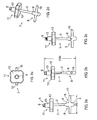
- FIGS 1 a to 1 h show a device (1) according to an embodiment of the present invention.
- the device (1) comprises a drive shaft (2) having a proximal end (3) and a distal end (4).
- the proximal end (3) has a protuberance (5) that can be gripped by any suitable means (for example a user's fingers or pliers) in order to apply a torque to the drive shaft (2).
- the distal end (4) of the drive shaft (2) has a cam (6).
- the cam (6) is disposed such that when a torque is applied to the drive shaft (2) via the proximal end (3) the cam (6) rotates and acts in a direction substantially parallel to the axis of the drive shaft (2).
- Figures 1a and 1b are side views of the device (1).
- Figure 1c is a bottom plan view, showing the cam (6).
- Figures 1d-g show the cam (6) in more detail.
- Figure 1h shows the protuberance (5) in more detail.
- a user can insert the distal end (4) into a cavity space between the leading face of a sleeve and the internal face of an implant head (see Figure 6 ) so that the cam (6) engages with the leading face of the sleeve and the internal face of the implant head.
- the user can then apply a torque to the drive shaft (2) via the protuberance (5) on the proximal end (3) of the drive shaft (2) so that the cam (6) rotates and thereby forces the sleeve and implant head apart.
- the user may apply a torque with his fingers if possible, or with pliers if more force is required.
- the protuberance (5) may provide an attachment point for a handle, as described herein.
- FIGS 2a-e show a device (7) according to another embodiment of the present invention.
- the figures show possible dimensions of the device (7) by way of example only, they are not limiting.
- the device (7) comprises a drive shaft (2) having a proximal end (3) and a distal end (4).
- the proximal end (3) has a handle (8) which comprises a body (9) and a cross bar (10).
- the handle (8) is attached to the protuberance (5) of Figures 1a-h .
- the handle enables a user to apply a torque to the proximal end (3) of the drive shaft (2).
- the distal end (4) of the drive shaft (2) has a cam (6).
- the cam (6) is disposed such that when a torque is applied to the drive shaft (2) via the handle (8), the cam (6) acts in a direction substantially parallel to the axis of the drive shaft (2).
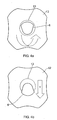
- the device (7) also has a body (11) which comprises a first portion (12) and a second portion (13).
- the body (11) is shown in more detail in Figures 3a-d .
- the diameter of the first portion (12) is greater than the diameter of the second portion (13).
- the first (12) and second (13) portions are aligned such that their centre-points are coaxial and the body is substantially T-shaped when viewed in cross-section (see Figures 2a-c , 3b ).
- the first portion (12) has four gripping points (15) disposed equidistantly around the periphery of the first portion (12).
- the second portion (13) is tapered so that it can engage with a tapered sleeve.
- a bore (14) extends through both the first (12) and second (13) portions. From Figures 2a,c and 3a,c,d it can be seen that the central axis of the bore (14) is offset from the main axis of the body (11) so that rotation of the drive shaft (2) results in eccentric motion of the cam (6) with respect to the body (11). This is illustrated in Figures 4a ,b. As shown in Figures 4a,b , rotation of the drive shaft (in this embodiment in a clockwise direction) causes the cam (6) to move out from within the confines of the second portion (13) of the body (11) in direction Y. As shown in Figure 5 , the drive shaft (2) and cam (6) can translate in the direction Z, parallel to the axis of the drive shaft (2).
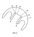
- Figure 6 shows a cross-section of an implant head (17) with a sleeve (16) inserted. As shown, there is a cavity space (18) between the leading face (19) of the sleeve (16) and the internal face (20) of the implant head (17). It is the cavity space (18) that receives the cam (6).
- the gap size of the cavity space (18) may be 1 mm or more.
- the gap size of the cavity space (18) may be 2-10 mm. Usually, the gap size of the cavity space is approximately 2 mm.
- Figures 7a-c show the device (7) of Figures 2a-e in use with an implant head (17).
- the distal end (4) of the device (7) is passed into the implant assembly through the rear of the sleeve (16) and allowed to advance until the distal end (4) is inserted into the cavity space (18) between the leading face (19) of the sleeve and the internal face (20) of the implant head (17) (see Figure 7a and Figure 6 ).
- the second portion (13) of the body (11) locates in the sleeve (16) and thereby centralises the body (11) in the sleeve (16).
- cam (6) acts in a direction substantially parallel to the axis of the drive shaft (2) (direction Z in Figure 5 ) such that it forces the sleeve (16) and implant head (17) apart (see Figure 7c ).
- the drive shaft (2)/cam(6) may be made of plastic.
- the drive shaft (2)/cam(6) is made of metal.
- the metal may be aluminium, titanium, stainless steel or a metal alloy.
- the metal is stainless steel.
- the handle (8) may be made of plastic.
- the handle (8) is made of metal.
- the metal may be aluminium, titanium, stainless steel or a metal alloy.
- the metal is stainless steel.
- the body (11) may be made of metal.
- the metal may be aluminium, titanium, stainless steel or a metal alloy.
- the body (11) is made of plastic.
- the plastic is polyacetal.
Abstract
Description
- The present invention relates to a separation device, and particularly a device for separating a sleeve from an implant head. For example, if an incorrect selection (either the head or sleeve) is made the sleeve can become stuck within an implant head, such as a hip implant head. In such circumstances, manual force applied directly by a user, i.e. without the aid of a device/tool, can be insufficient to remove the sleeve. Accordingly, a suitable device is required.
- Existing taper sleeves have an internal screw thread at the base of the taper. To remove such taper sleeves, a device with a threaded spigot is used to thread through the bottom surface of the taper sleeve and bear against the recessed internal face of the implant head, thereby forcing the sleeve and the implant head apart. Such a device will not work with a sleeve lacking a screw thread.
- Such sleeves require there to be sufficient space for a bottom surface at the base of the sleeve. In some cases where space is limited there is not sufficient space and therefore such sleeves cannot be used.
- Sleeves having threaded portions are more difficult to manufacture than those without threaded portions.
- Sleeves having threaded portions are prone to failure due to thread burring caused by the threaded spigot separation device.
- The documents
DE19833791 A1 andUS-A-4787907 each disclose a device for separating a sleeve from an implant head comprising a drive shaft having a proximal end and a distal end, the distal end having a cam. - An aim of the present invention is to provide a device that can efficiently separate a sleeve from an implant head, regardless of whether the sleeve has a screw thread or not, without causing any damage to the sleeve.
- According to a first aspect of the present invention, there is provided a device for separating a sleeve from an implant head as defined in claim 1.
- The device can remove both threaded and non-threaded sleeves from an implant head. The device is simple to use and requires minimal force in order to effect separation of the sleeve and implant head. The device does not damage the sleeve. The device enables a surgeon to use non-threaded sleeves, which are easier to manufacture than threaded sleeves, less prone to damage than threaded sleeves (when removed by a threaded spigot separation device), and which can be utilised where space is limited and closed tapers are not possible.
- The drive shaft may have a length in the range 40-80 mm. The drive shaft may have a length in the range 50-70 mm. The drive shaft may have a length in the range 55-65 mm.
- The drive shaft may have a diameter in the range 4-8 mm. The drive shaft may have a diameter in the range 5-7 mm.
- The cam may have an angle in the range 10-14° measured relative to the plane that is perpendicular to the axis of the drive shaft. The cam may have an angle in the range 11-13°. The cam may have an angle of approximately 12°.
- The cam is sized so that the leading edges are smaller than the gap size of the cavity space. The cam is sized so that as the cam is rotated the cam increases to greater than the gap size. The cam may be sized so that as the cam is rotated through 180° the cam increases to greater than the gap size. The cam may be sized so that as the cam is rotated through 180° the cam increases to 1.1-2 times the gap size. The cam may be sized so that as the cam is rotated through 180° the cam increases to 1.5 times the gap size. The proximal end of the device may have a handle, such that, in use, a torque is applied to the drive shaft via the handle.
- The handle may comprise a bar disposed perpendicular to the proximal end of the drive shaft. The bar may be disposed such that the bar and the drive shaft form an L-shape. The bar may be disposed such that the bar and the drive shaft form a T-shape.
- According to a preferred embodiment of the present invention, the device further comprises a body for engaging with the sleeve, the body having a bore for receiving the drive shaft.
- The diameter of the bore may be greater than the diameter of the drive shaft, thereby enabling translation of the cam in a plane substantially perpendicular to the axis defined by the bore.
- The bore may have a diameter in the range 4-12 mm. The bore may have a diameter in the range 4-10 mm. The bore may have a diameter in the range 4-8 mm. The bore may have a diameter in the range 5-7 mm.
- The axis of the bore may be offset from the main axis of the body so that rotation of the drive shaft results in eccentric motion of the cam with respect to the body.
- The body may be tapered so that it can engage with a tapered sleeve.
- The body and the drive shaft may have guide marks such that when the guide marks on the body and the drive shaft are aligned, this indicates to a user that the cam is optimally oriented with respect to the body in order to enable insertion into the sleeve.
- The body may have a first portion and a second portion, the first and second portions being cylindrical, the first portion having a greater diameter than the second portion, the first and second portions being aligned such that their centre-points are coaxial and the body is substantially T-shaped when viewed in cross-section. The bore extends through both the first and second portions.
- The first portion may have a diameter in the range 25-75 mm. The first portion may have a diameter in the range 35-65 mm. The first portion may have a diameter in the range 45-55 mm.
- The second portion may have a diameter in the range 10-20 mm. The second portion may have a diameter in the range 10-15 mm. The second portion may have a diameter in the range 11-13 mm.
- The combined length of the first and second portions measured along the bore axis may be in the range 20-50 mm. The combined length may be 20-40 mm. The combined length may be 20-30 mm. The combined length may be 25-30 mm.
- The first portion of the body may be shaped so that it can be gripped by a user. For example, the first portion may be based on a cylinder with parts of the periphery removed in order to provide indentations that can act as gripping points. The first portion may have at least two gripping points. The first portion may have two opposing gripping points. The first portion may have three gripping points disposed equidistantly around its periphery. The first portion may have four gripping points disposed equidistantly around its periphery.
- The second portion of the body may be tapered so that it can engage with a tapered sleeve.
- The drive shaft/cam may be made of plastic. Preferably, the drive shaft/cam is made of metal. The metal may be aluminium, titanium, stainless steel or a metal alloy. Preferably, the metal is stainless steel.
- The handle may be made of plastic. Preferably, the handle is made of metal. The metal may be aluminium, titanium, stainless steel or a metal alloy. Preferably, the metal is stainless steel.
- The body may be made of metal. The metal may be aluminium, titanium, stainless steel or a metal alloy. Preferably, the body is made of plastic. Preferably, the plastic is polyacetal.
- According to a second aspect of the present invention, there is provided a method of separating a sleeve from an implant head as defined in
claim 12. - Preferably, the proximal end of the device has a handle and torque is applied to the drive shaft via the handle.
- The handle may comprise a bar disposed perpendicular to the proximal end of the drive shaft. The bar may be disposed such that the bar and the drive shaft form an L-shape. The bar may be disposed such that the bar and the drive shaft form a T-shape.
- According to a preferred embodiment of the present invention, the device further comprises a body for engaging with the sleeve, the body having a bore for receiving the drive shaft, and wherein the body is disposed so that it engages with the sleeve.
- The diameter of the bore may be greater than the diameter of the drive shaft, thereby enabling translation of the cam in a plane substantially perpendicular to the axis defined by the bore, so that when the cam is moved within the cavity space it engages with the leading face of the sleeve and the internal face of the implant head.
- The axis of the bore may be offset from the main axis of the body so that rotation of the drive shaft results in eccentric motion of the cam with respect to the body, thereby enabling the cam to move from a first position within the confines of the body to a second position outside the confines of the body, such that when the cam is in the second position it is disposed in the cavity space so that it engages with the leading face of the sleeve and the internal face of the implant head.
- The sleeve may be tapered. The sleeve may have two tapers, one internal to engage with the male taper of a hip stem, for example, and one external to engage with the internal taper of the implant head.
- The body of the device may be tapered so that it can engage with a tapered sleeve.
- The drive shaft/cam may be made of plastic. Preferably, the drive shaft/cam is made of metal. The metal may be aluminium, titanium, stainless steel or a metal alloy. Preferably, the metal is stainless steel.
- The handle may be made of plastic. Preferably, the handle is made of metal. The metal may be aluminium, titanium, stainless steel or a metal alloy. Preferably, the metal is stainless steel.
- The body may be made of metal. The metal may be aluminium, titanium, stainless steel or a metal alloy. Preferably, the body is made of plastic. Preferably, the plastic is polyacetal.
- The implant head may be part of a hip implant.
- According to a third aspect of the present invention, there is provided a kit of parts according to
claim 19. - Reference will now be made, by way of example, to the accompanying drawings, in which:
-
Figures 1a-h show various views of a device according to an embodiment of the present invention; -
Figures 2a-e show various views of a device according to another embodiment of the present invention; -
Figures 3a-d show various views of a component of the device shown inFigures 2a-e ; -
Figures 4a,b show bottom plan views of the device ofFigures 2a-e ; -
Figure 5 shows a side view of the device ofFigures 2a-e ; -
Figure 6 shows a cross-section of an implant head with a sleeve inserted; and -
Figures 7a-c show various views of the device ofFigures 2a-e in use with an implant head and sleeve. -
Figures 1 a to 1 h show a device (1) according to an embodiment of the present invention. The device (1) comprises a drive shaft (2) having a proximal end (3) and a distal end (4). The proximal end (3) has a protuberance (5) that can be gripped by any suitable means (for example a user's fingers or pliers) in order to apply a torque to the drive shaft (2). The distal end (4) of the drive shaft (2) has a cam (6). The cam (6) is disposed such that when a torque is applied to the drive shaft (2) via the proximal end (3) the cam (6) rotates and acts in a direction substantially parallel to the axis of the drive shaft (2). -
Figures 1a and 1b are side views of the device (1).Figure 1c is a bottom plan view, showing the cam (6).Figures 1d-g show the cam (6) in more detail.Figure 1h shows the protuberance (5) in more detail. - A user can insert the distal end (4) into a cavity space between the leading face of a sleeve and the internal face of an implant head (see
Figure 6 ) so that the cam (6) engages with the leading face of the sleeve and the internal face of the implant head. The user can then apply a torque to the drive shaft (2) via the protuberance (5) on the proximal end (3) of the drive shaft (2) so that the cam (6) rotates and thereby forces the sleeve and implant head apart. The user may apply a torque with his fingers if possible, or with pliers if more force is required. The protuberance (5) may provide an attachment point for a handle, as described herein. -
Figures 2a-e show a device (7) according to another embodiment of the present invention. The figures show possible dimensions of the device (7) by way of example only, they are not limiting. The device (7) comprises a drive shaft (2) having a proximal end (3) and a distal end (4). The proximal end (3) has a handle (8) which comprises a body (9) and a cross bar (10). The handle (8) is attached to the protuberance (5) ofFigures 1a-h . The handle enables a user to apply a torque to the proximal end (3) of the drive shaft (2). The distal end (4) of the drive shaft (2) has a cam (6). The cam (6) is disposed such that when a torque is applied to the drive shaft (2) via the handle (8), the cam (6) acts in a direction substantially parallel to the axis of the drive shaft (2). - The device (7) also has a body (11) which comprises a first portion (12) and a second portion (13). The body (11) is shown in more detail in
Figures 3a-d . The diameter of the first portion (12) is greater than the diameter of the second portion (13). The first (12) and second (13) portions are aligned such that their centre-points are coaxial and the body is substantially T-shaped when viewed in cross-section (seeFigures 2a-c ,3b ). The first portion (12) has four gripping points (15) disposed equidistantly around the periphery of the first portion (12). The second portion (13) is tapered so that it can engage with a tapered sleeve. - As shown in
Figure 3d , a bore (14) extends through both the first (12) and second (13) portions. FromFigures 2a,c and3a,c,d it can be seen that the central axis of the bore (14) is offset from the main axis of the body (11) so that rotation of the drive shaft (2) results in eccentric motion of the cam (6) with respect to the body (11). This is illustrated inFigures 4a ,b. As shown inFigures 4a,b , rotation of the drive shaft (in this embodiment in a clockwise direction) causes the cam (6) to move out from within the confines of the second portion (13) of the body (11) in direction Y. As shown inFigure 5 , the drive shaft (2) and cam (6) can translate in the direction Z, parallel to the axis of the drive shaft (2). -
Figure 6 shows a cross-section of an implant head (17) with a sleeve (16) inserted. As shown, there is a cavity space (18) between the leading face (19) of the sleeve (16) and the internal face (20) of the implant head (17). It is the cavity space (18) that receives the cam (6). The gap size of the cavity space (18) may be 1 mm or more. The gap size of the cavity space (18) may be 2-10 mm. Usually, the gap size of the cavity space is approximately 2 mm. -
Figures 7a-c show the device (7) ofFigures 2a-e in use with an implant head (17). The distal end (4) of the device (7) is passed into the implant assembly through the rear of the sleeve (16) and allowed to advance until the distal end (4) is inserted into the cavity space (18) between the leading face (19) of the sleeve and the internal face (20) of the implant head (17) (seeFigure 7a andFigure 6 ). The second portion (13) of the body (11) locates in the sleeve (16) and thereby centralises the body (11) in the sleeve (16). - As shown in
Figure 7b , a torque is applied to the handle (8) so that the drive shaft (2) rotates. FromFigures 4a,b it can be seen that such rotation of the drive shaft (2) causes the cam (6) to move out from within the confines of the second portion (13) of the body (11) in direction Y. Consequently, the cam (6) moves in the cavity space (18) and the leading edges of the cam (6) engage with the leading face (19) of the sleeve (16) and the internal face (20) of the implant head (17) (seeFigure 6 ). As the rotation of the drive shaft (2) and cam (6) continues the cam (6) acts in a direction substantially parallel to the axis of the drive shaft (2) (direction Z inFigure 5 ) such that it forces the sleeve (16) and implant head (17) apart (seeFigure 7c ). - The drive shaft (2)/cam(6) may be made of plastic. Preferably, the drive shaft (2)/cam(6) is made of metal. The metal may be aluminium, titanium, stainless steel or a metal alloy. Preferably, the metal is stainless steel.
- The handle (8) may be made of plastic. Preferably, the handle (8) is made of metal. The metal may be aluminium, titanium, stainless steel or a metal alloy. Preferably, the metal is stainless steel.
- The body (11) may be made of metal. The metal may be aluminium, titanium, stainless steel or a metal alloy. Preferably, the body (11) is made of plastic. Preferably, the plastic is polyacetal.
Claims (19)
- A device (1, 7) for separating a sleeve (16) from an implant head (17), comprising a drive shaft (2) having a proximal end (3) and a distal end (4), the distal end (4) having a cam (6), wherein the cam (6) is disposed such that when, in use a torque is applied to the drive shaft (2) about an axis of the drive shaft (2) via the proximal end (3) the cam (6) rotates and acts in a direction substantially parallel to the axis.
- A device (7) according to claim 1, further comprising a body (11) for engaging with the sleeve (16), the body (11) having a bore (14) for receiving the drive shaft (2).
- A device (7) according to claim 2, wherein the diameter of the bore (14) is greater than the diameter of the drive shaft (2), thereby enabling translation of the cam (6) In a plane substantially perpendicular to the axis defined by the bore (14).
- A device (7) according to claim 2, wherein the axis of the bore (14) is offset from the main axis of the body (11) so that rotation of the drive shaft (2) results in eccentric motion of the cam (6) with respect to the body.
- A device (7) according to any preceding claim, wherein the body (11) is tapered so that it can engage with a tapered sleeve.
- A device (1, 7) according to any preceding claim, wherein the proximal end (3) has a handle (8), and wherein, in use, a torque is applied to the drive shaft (2) via the handle (8).
- A device (7) according to claim 6, wherein the handle (8) comprises a bar (10) disposed perpendicular to the proximal end (3) of the drive shaft (2).
- A device (7) according to claim 7, wherein the bar (10) is disposed such that the bar (10) and the drive shaft (2) form a T-shape.
- A device (1, 7) according to any preceding claim, wherein the drive shaft/cam (2/6) is made of metal.
- A device (7) according to any preceding claim, wherein the handle (8) is made of metal.
- A device (7) according to any preceding claim, wherein the body (11) is made of plastic.
- A method of separating a sleeve (16) from an implant head (17), comprising:providing a device (1, 7) comprising a drive shaft (2) having a proximal end (3) and a distal end (4), the distal end (4) having a cam (6), wherein the cam (6) is disposed such that when a torque is applied to the drive shaft (2) about an axis of the drive shaft (2) via the proximal end (3) the cam (6) rotates and acts in a direction substantially parallel to the axis ;inserting the distal end (4) into a cavity space between the leading face of the sleeve (16) and the internal face of the implant head (17) so that the cam (6) engages with the leading face of the sleeve (16) and the internal face of the implant head (17);applying a torque to the drive shaft (2) via the proximal end (3) so that the cam (6) rotates and thereby forces the sleeve (16) and the implant head (17) apart.
- A method according to claim 12, wherein the proximal end (3) of the device (1, 7) has a handle (8), and wherein a torque is applied to the drive shaft (2) via the handle (8).
- A method according to claim 12 or 13, wherein the device (1, 7) further comprises a body (11) for engaging with the sleeve (16), the body (11) having a bore (14) for receiving the drive shaft (2), and wherein the body (11) is disposed so that it engages with the sleeve (16).
- A method according to claim 14, wherein the diameter of the bore (14) Is greater than the diameter of the drive shaft (2), thereby enabling translation of the cam (6) In a plane substantially perpendicular to the axis defined by the bore (14), and wherein the cam (6) is moved within the cavity space so that it engages with the leading face of the sleeve (16) and the internal face of the implant head (17).
- A method according to claim 14, wherein the axis of the bore (14) is offset from the main axis of the body (11) so that rotation of the drive shaft (2) results in eccentric motion of the cam (6) with respect to the body (11), thereby enabling the cam (6) to move from a first position within the confines of the body (11) to a second position outside the confines of the body (11), such that when the cam (6) is in the second position it is disposed in the cavity space so that it engages with the leading face of the sleeve (16) and the internal face of the implant head (17).
- A method according to any of claims 12 to 16, using a device (1, 7) according to any of claims 5 to 11.
- A method according to any of claims 12 to 17, wherein the implant head (17) is part of a hip implant.
- A kit of parts comprising a device (1, 7) according to any of claims 2 to 11 and at least one sleeve (16), the body (11) of the device and the at least one sleeve being shaped so that they engage one another.
Applications Claiming Priority (2)
| Application Number | Priority Date | Filing Date | Title |
|---|---|---|---|
| GBGB0613359.9A GB0613359D0 (en) | 2006-07-05 | 2006-07-05 | Separation device |
| PCT/GB2007/002489 WO2008003957A2 (en) | 2006-07-05 | 2007-07-04 | Separation device |
Publications (2)
| Publication Number | Publication Date |
|---|---|
| EP2043564A2 EP2043564A2 (en) | 2009-04-08 |
| EP2043564B1 true EP2043564B1 (en) | 2011-12-21 |
Family
ID=36926504
Family Applications (1)
| Application Number | Title | Priority Date | Filing Date |
|---|---|---|---|
| EP07733454A Not-in-force EP2043564B1 (en) | 2006-07-05 | 2007-07-04 | Separation device |
Country Status (10)
| Country | Link |
|---|---|
| US (1) | US9056021B2 (en) |
| EP (1) | EP2043564B1 (en) |
| JP (1) | JP5059857B2 (en) |
| CN (1) | CN101489505B (en) |
| AT (1) | ATE537787T1 (en) |
| AU (1) | AU2007270930B2 (en) |
| CA (1) | CA2656348A1 (en) |
| ES (1) | ES2379398T3 (en) |
| GB (1) | GB0613359D0 (en) |
| WO (1) | WO2008003957A2 (en) |
Family Cites Families (13)
| Publication number | Priority date | Publication date | Assignee | Title |
|---|---|---|---|---|
| JPS5044637Y1 (en) * | 1970-12-29 | 1975-12-18 | ||
| JPS604706Y2 (en) * | 1980-09-06 | 1985-02-12 | 富士重工業株式会社 | piston pin removal tool |
| JPS58126180U (en) * | 1982-02-19 | 1983-08-27 | 日東電工株式会社 | Tubular membrane module adapter extraction jig |
| US4787907A (en) * | 1987-02-03 | 1988-11-29 | Techmedica, Inc. | Morse taper |
| US5362311A (en) * | 1990-01-05 | 1994-11-08 | Kyocera Corporation | Artificial hip joint |
| US5116339A (en) * | 1990-07-11 | 1992-05-26 | Glock Steven R | Acetabular cup installation tool and method of installing an acetabular cup |
| JP3645326B2 (en) * | 1995-09-27 | 2005-05-11 | 豊田鉄工株式会社 | Extraction tool for press-fitting bush |
| US6132469A (en) * | 1997-11-07 | 2000-10-17 | Biomet, Inc. | Acetabular liner extractor |
| DE19833791A1 (en) * | 1998-07-21 | 2000-01-27 | Merete Management Gmbh | Tool for fitting or removing ball in joint prosthesis |
| JP2002370179A (en) * | 2001-06-15 | 2002-12-24 | Ryouke Tekko:Kk | Removing apparatus for parts |
| DE20114835U1 (en) * | 2001-09-03 | 2001-12-06 | Merete Medical Gmbh | Adapter and puller for hip joints |
| US7024972B2 (en) * | 2003-05-27 | 2006-04-11 | Wj Technologies, Inc. | Tool for removing and tightening screw-on drains |
| US7927376B2 (en) * | 2005-06-30 | 2011-04-19 | Depuy Products, Inc. | Expandable acetabular liner extraction device, cup assembly and associated method |
-
2006
- 2006-07-05 GB GBGB0613359.9A patent/GB0613359D0/en not_active Ceased
-
2007
- 2007-07-04 AT AT07733454T patent/ATE537787T1/en active
- 2007-07-04 JP JP2009517422A patent/JP5059857B2/en not_active Expired - Fee Related
- 2007-07-04 ES ES07733454T patent/ES2379398T3/en active Active
- 2007-07-04 US US12/307,419 patent/US9056021B2/en active Active
- 2007-07-04 AU AU2007270930A patent/AU2007270930B2/en not_active Ceased
- 2007-07-04 CA CA002656348A patent/CA2656348A1/en not_active Abandoned
- 2007-07-04 EP EP07733454A patent/EP2043564B1/en not_active Not-in-force
- 2007-07-04 WO PCT/GB2007/002489 patent/WO2008003957A2/en active Application Filing
- 2007-07-04 CN CN2007800255244A patent/CN101489505B/en not_active Expired - Fee Related
Also Published As
| Publication number | Publication date |
|---|---|
| GB0613359D0 (en) | 2006-08-16 |
| WO2008003957A2 (en) | 2008-01-10 |
| AU2007270930B2 (en) | 2014-01-16 |
| ES2379398T3 (en) | 2012-04-25 |
| EP2043564A2 (en) | 2009-04-08 |
| CN101489505B (en) | 2012-03-21 |
| US9056021B2 (en) | 2015-06-16 |
| ATE537787T1 (en) | 2012-01-15 |
| JP5059857B2 (en) | 2012-10-31 |
| WO2008003957A3 (en) | 2008-02-21 |
| US20090281547A1 (en) | 2009-11-12 |
| AU2007270930A1 (en) | 2008-01-10 |
| CN101489505A (en) | 2009-07-22 |
| JP2009542273A (en) | 2009-12-03 |
| CA2656348A1 (en) | 2008-01-10 |
Similar Documents
| Publication | Publication Date | Title |
|---|---|---|
| CN108366863B (en) | Retainer for resurfacing head implant | |
| CN101160100B (en) | Forceps and system using same | |
| JP2011527613A (en) | Minimal open surgery tool for hip prosthesis | |
| US9888948B2 (en) | Device for guiding a surgical instrument into position on a bone-anchor element including a means for realigning a link rod with the anchor element, and related system of surgical instruments | |
| AU2006238831B2 (en) | Screw extraction and insertion device | |
| CA2548460C (en) | Impacting device and method | |
| US9840002B2 (en) | Modular driver and screw system | |
| EP2043564B1 (en) | Separation device | |
| US5694672A (en) | Bolt and pin extraction tool | |
| EP3771443B1 (en) | Tool holder for modular tool | |
| WO1997016281A9 (en) | Bolt and pin extraction tool | |
| EP3771441B1 (en) | Handle for modular tool | |
| JP2007276024A (en) | Adapter for use in pliers for remote operation | |
| US20150059538A1 (en) | Screw grabber | |
| CN105252492A (en) | Fastener removal socket | |
| KR102469392B1 (en) | Instrument for handling a dental part | |
| JP6525842B2 (en) | Surgical grasper | |
| JP4477562B2 (en) | Guide device for bone surgery | |
| US20180161044A1 (en) | Orthopedic instrumentation | |
| US20130284785A1 (en) | Tungsten carbide ring cracker | |
| WO2016176676A1 (en) | Swivel adjustment system for fastener pulling heads | |
| JP2007038324A (en) | Attaching/detaching tool for e-type snap ring | |
| CA3136177A1 (en) | Power drive adapter tool |
Legal Events
| Date | Code | Title | Description |
|---|---|---|---|
| PUAI | Public reference made under article 153(3) epc to a published international application that has entered the european phase |
Free format text: ORIGINAL CODE: 0009012 |
|
| 17P | Request for examination filed |
Effective date: 20090203 |
|
| AK | Designated contracting states |
Kind code of ref document: A2 Designated state(s): AT BE BG CH CY CZ DE DK EE ES FI FR GB GR HU IE IS IT LI LT LU LV MC MT NL PL PT RO SE SI SK TR |
|
| AX | Request for extension of the european patent |
Extension state: AL BA HR MK RS |
|
| DAX | Request for extension of the european patent (deleted) | ||
| 17Q | First examination report despatched |
Effective date: 20091215 |
|
| GRAC | Information related to communication of intention to grant a patent modified |
Free format text: ORIGINAL CODE: EPIDOSCIGR1 |
|
| GRAP | Despatch of communication of intention to grant a patent |
Free format text: ORIGINAL CODE: EPIDOSNIGR1 |
|
| GRAS | Grant fee paid |
Free format text: ORIGINAL CODE: EPIDOSNIGR3 |
|
| GRAA | (expected) grant |
Free format text: ORIGINAL CODE: 0009210 |
|
| AK | Designated contracting states |
Kind code of ref document: B1 Designated state(s): AT BE BG CH CY CZ DE DK EE ES FI FR GB GR HU IE IS IT LI LT LU LV MC MT NL PL PT RO SE SI SK TR |
|
| REG | Reference to a national code |
Ref country code: GB Ref legal event code: FG4D |
|
| REG | Reference to a national code |
Ref country code: CH Ref legal event code: EP |
|
| REG | Reference to a national code |
Ref country code: AT Ref legal event code: REF Ref document number: 537787 Country of ref document: AT Kind code of ref document: T Effective date: 20120115 |
|
| REG | Reference to a national code |
Ref country code: IE Ref legal event code: FG4D |
|
| REG | Reference to a national code |
Ref country code: CH Ref legal event code: NV Representative=s name: MURGITROYD & COMPANY |
|
| REG | Reference to a national code |
Ref country code: DE Ref legal event code: R096 Ref document number: 602007019513 Country of ref document: DE Effective date: 20120308 |
|
| REG | Reference to a national code |
Ref country code: NL Ref legal event code: T3 |
|
| REG | Reference to a national code |
Ref country code: ES Ref legal event code: FG2A Ref document number: 2379398 Country of ref document: ES Kind code of ref document: T3 Effective date: 20120425 |
|
| PG25 | Lapsed in a contracting state [announced via postgrant information from national office to epo] |
Ref country code: LT Free format text: LAPSE BECAUSE OF FAILURE TO SUBMIT A TRANSLATION OF THE DESCRIPTION OR TO PAY THE FEE WITHIN THE PRESCRIBED TIME-LIMIT Effective date: 20111221 |
|
| LTIE | Lt: invalidation of european patent or patent extension |
Effective date: 20111221 |
|
| PG25 | Lapsed in a contracting state [announced via postgrant information from national office to epo] |
Ref country code: GR Free format text: LAPSE BECAUSE OF FAILURE TO SUBMIT A TRANSLATION OF THE DESCRIPTION OR TO PAY THE FEE WITHIN THE PRESCRIBED TIME-LIMIT Effective date: 20120322 Ref country code: SI Free format text: LAPSE BECAUSE OF FAILURE TO SUBMIT A TRANSLATION OF THE DESCRIPTION OR TO PAY THE FEE WITHIN THE PRESCRIBED TIME-LIMIT Effective date: 20111221 Ref country code: SE Free format text: LAPSE BECAUSE OF FAILURE TO SUBMIT A TRANSLATION OF THE DESCRIPTION OR TO PAY THE FEE WITHIN THE PRESCRIBED TIME-LIMIT Effective date: 20111221 Ref country code: LV Free format text: LAPSE BECAUSE OF FAILURE TO SUBMIT A TRANSLATION OF THE DESCRIPTION OR TO PAY THE FEE WITHIN THE PRESCRIBED TIME-LIMIT Effective date: 20111221 |
|
| PG25 | Lapsed in a contracting state [announced via postgrant information from national office to epo] |
Ref country code: CY Free format text: LAPSE BECAUSE OF FAILURE TO SUBMIT A TRANSLATION OF THE DESCRIPTION OR TO PAY THE FEE WITHIN THE PRESCRIBED TIME-LIMIT Effective date: 20111221 |
|
| PG25 | Lapsed in a contracting state [announced via postgrant information from national office to epo] |
Ref country code: SK Free format text: LAPSE BECAUSE OF FAILURE TO SUBMIT A TRANSLATION OF THE DESCRIPTION OR TO PAY THE FEE WITHIN THE PRESCRIBED TIME-LIMIT Effective date: 20111221 Ref country code: EE Free format text: LAPSE BECAUSE OF FAILURE TO SUBMIT A TRANSLATION OF THE DESCRIPTION OR TO PAY THE FEE WITHIN THE PRESCRIBED TIME-LIMIT Effective date: 20111221 Ref country code: BG Free format text: LAPSE BECAUSE OF FAILURE TO SUBMIT A TRANSLATION OF THE DESCRIPTION OR TO PAY THE FEE WITHIN THE PRESCRIBED TIME-LIMIT Effective date: 20120321 Ref country code: IS Free format text: LAPSE BECAUSE OF FAILURE TO SUBMIT A TRANSLATION OF THE DESCRIPTION OR TO PAY THE FEE WITHIN THE PRESCRIBED TIME-LIMIT Effective date: 20120421 Ref country code: CZ Free format text: LAPSE BECAUSE OF FAILURE TO SUBMIT A TRANSLATION OF THE DESCRIPTION OR TO PAY THE FEE WITHIN THE PRESCRIBED TIME-LIMIT Effective date: 20111221 |
|
| PG25 | Lapsed in a contracting state [announced via postgrant information from national office to epo] |
Ref country code: PT Free format text: LAPSE BECAUSE OF FAILURE TO SUBMIT A TRANSLATION OF THE DESCRIPTION OR TO PAY THE FEE WITHIN THE PRESCRIBED TIME-LIMIT Effective date: 20120423 Ref country code: PL Free format text: LAPSE BECAUSE OF FAILURE TO SUBMIT A TRANSLATION OF THE DESCRIPTION OR TO PAY THE FEE WITHIN THE PRESCRIBED TIME-LIMIT Effective date: 20111221 Ref country code: RO Free format text: LAPSE BECAUSE OF FAILURE TO SUBMIT A TRANSLATION OF THE DESCRIPTION OR TO PAY THE FEE WITHIN THE PRESCRIBED TIME-LIMIT Effective date: 20111221 |
|
| REG | Reference to a national code |
Ref country code: AT Ref legal event code: MK05 Ref document number: 537787 Country of ref document: AT Kind code of ref document: T Effective date: 20111221 |
|
| PLBE | No opposition filed within time limit |
Free format text: ORIGINAL CODE: 0009261 |
|
| STAA | Information on the status of an ep patent application or granted ep patent |
Free format text: STATUS: NO OPPOSITION FILED WITHIN TIME LIMIT |
|
| PG25 | Lapsed in a contracting state [announced via postgrant information from national office to epo] |
Ref country code: DK Free format text: LAPSE BECAUSE OF FAILURE TO SUBMIT A TRANSLATION OF THE DESCRIPTION OR TO PAY THE FEE WITHIN THE PRESCRIBED TIME-LIMIT Effective date: 20111221 |
|
| 26N | No opposition filed |
Effective date: 20120924 |
|
| REG | Reference to a national code |
Ref country code: DE Ref legal event code: R097 Ref document number: 602007019513 Country of ref document: DE Effective date: 20120924 |
|
| PG25 | Lapsed in a contracting state [announced via postgrant information from national office to epo] |
Ref country code: AT Free format text: LAPSE BECAUSE OF FAILURE TO SUBMIT A TRANSLATION OF THE DESCRIPTION OR TO PAY THE FEE WITHIN THE PRESCRIBED TIME-LIMIT Effective date: 20111221 |
|
| PG25 | Lapsed in a contracting state [announced via postgrant information from national office to epo] |
Ref country code: MC Free format text: LAPSE BECAUSE OF NON-PAYMENT OF DUE FEES Effective date: 20120731 |
|
| REG | Reference to a national code |
Ref country code: IE Ref legal event code: MM4A |
|
| PG25 | Lapsed in a contracting state [announced via postgrant information from national office to epo] |
Ref country code: FI Free format text: LAPSE BECAUSE OF FAILURE TO SUBMIT A TRANSLATION OF THE DESCRIPTION OR TO PAY THE FEE WITHIN THE PRESCRIBED TIME-LIMIT Effective date: 20111221 |
|
| PG25 | Lapsed in a contracting state [announced via postgrant information from national office to epo] |
Ref country code: IE Free format text: LAPSE BECAUSE OF NON-PAYMENT OF DUE FEES Effective date: 20120704 Ref country code: MT Free format text: LAPSE BECAUSE OF FAILURE TO SUBMIT A TRANSLATION OF THE DESCRIPTION OR TO PAY THE FEE WITHIN THE PRESCRIBED TIME-LIMIT Effective date: 20111221 |
|
| PG25 | Lapsed in a contracting state [announced via postgrant information from national office to epo] |
Ref country code: TR Free format text: LAPSE BECAUSE OF FAILURE TO SUBMIT A TRANSLATION OF THE DESCRIPTION OR TO PAY THE FEE WITHIN THE PRESCRIBED TIME-LIMIT Effective date: 20111221 |
|
| PG25 | Lapsed in a contracting state [announced via postgrant information from national office to epo] |
Ref country code: LU Free format text: LAPSE BECAUSE OF NON-PAYMENT OF DUE FEES Effective date: 20120704 |
|
| PG25 | Lapsed in a contracting state [announced via postgrant information from national office to epo] |
Ref country code: HU Free format text: LAPSE BECAUSE OF FAILURE TO SUBMIT A TRANSLATION OF THE DESCRIPTION OR TO PAY THE FEE WITHIN THE PRESCRIBED TIME-LIMIT Effective date: 20070704 |
|
| REG | Reference to a national code |
Ref country code: FR Ref legal event code: PLFP Year of fee payment: 10 |
|
| REG | Reference to a national code |
Ref country code: FR Ref legal event code: PLFP Year of fee payment: 11 |
|
| REG | Reference to a national code |
Ref country code: FR Ref legal event code: PLFP Year of fee payment: 12 |
|
| REG | Reference to a national code |
Ref country code: CH Ref legal event code: PCOW Free format text: NEW ADDRESS: BUILDING 5, CROXLEY PARK HATTERS LANE, WATFORD, HERTFORDSHIRE WD18 8YE (GB) |
|
| REG | Reference to a national code |
Ref country code: DE Ref legal event code: R082 Ref document number: 602007019513 Country of ref document: DE Representative=s name: MURGITROYD & COMPANY, DE Ref country code: DE Ref legal event code: R081 Ref document number: 602007019513 Country of ref document: DE Owner name: SMITH & NEPHEW PLC, WATFORD, GB Free format text: FORMER OWNER: SMITH & NEPHEW PLC, LONDON, GB |
|
| REG | Reference to a national code |
Ref country code: BE Ref legal event code: PD Owner name: SMITH & NEPHEW PLC; GB Free format text: DETAILS ASSIGNMENT: CHANGE OF OWNER(S), AUTRE, ADRESSE; FORMER OWNER NAME: SMITH & NEPHEW, PLC Effective date: 20190628 |
|
| PGFP | Annual fee paid to national office [announced via postgrant information from national office to epo] |
Ref country code: FR Payment date: 20200625 Year of fee payment: 14 |
|
| PGFP | Annual fee paid to national office [announced via postgrant information from national office to epo] |
Ref country code: BE Payment date: 20200624 Year of fee payment: 14 Ref country code: NL Payment date: 20200625 Year of fee payment: 14 Ref country code: GB Payment date: 20200624 Year of fee payment: 14 |
|
| PGFP | Annual fee paid to national office [announced via postgrant information from national office to epo] |
Ref country code: DE Payment date: 20200624 Year of fee payment: 14 Ref country code: ES Payment date: 20200803 Year of fee payment: 14 |
|
| PGFP | Annual fee paid to national office [announced via postgrant information from national office to epo] |
Ref country code: CH Payment date: 20200716 Year of fee payment: 14 Ref country code: IT Payment date: 20200625 Year of fee payment: 14 |
|
| REG | Reference to a national code |
Ref country code: DE Ref legal event code: R119 Ref document number: 602007019513 Country of ref document: DE |
|
| REG | Reference to a national code |
Ref country code: CH Ref legal event code: PL |
|
| REG | Reference to a national code |
Ref country code: NL Ref legal event code: MM Effective date: 20210801 |
|
| GBPC | Gb: european patent ceased through non-payment of renewal fee |
Effective date: 20210704 |
|
| REG | Reference to a national code |
Ref country code: BE Ref legal event code: MM Effective date: 20210731 |
|
| PG25 | Lapsed in a contracting state [announced via postgrant information from national office to epo] |
Ref country code: LI Free format text: LAPSE BECAUSE OF NON-PAYMENT OF DUE FEES Effective date: 20210731 Ref country code: GB Free format text: LAPSE BECAUSE OF NON-PAYMENT OF DUE FEES Effective date: 20210704 Ref country code: DE Free format text: LAPSE BECAUSE OF NON-PAYMENT OF DUE FEES Effective date: 20220201 Ref country code: CH Free format text: LAPSE BECAUSE OF NON-PAYMENT OF DUE FEES Effective date: 20210731 |
|
| PG25 | Lapsed in a contracting state [announced via postgrant information from national office to epo] |
Ref country code: NL Free format text: LAPSE BECAUSE OF NON-PAYMENT OF DUE FEES Effective date: 20210801 Ref country code: FR Free format text: LAPSE BECAUSE OF NON-PAYMENT OF DUE FEES Effective date: 20210731 |
|
| PG25 | Lapsed in a contracting state [announced via postgrant information from national office to epo] |
Ref country code: IT Free format text: LAPSE BECAUSE OF NON-PAYMENT OF DUE FEES Effective date: 20210704 Ref country code: BE Free format text: LAPSE BECAUSE OF NON-PAYMENT OF DUE FEES Effective date: 20210731 |
|
| REG | Reference to a national code |
Ref country code: ES Ref legal event code: FD2A Effective date: 20220902 |
|
| PG25 | Lapsed in a contracting state [announced via postgrant information from national office to epo] |
Ref country code: ES Free format text: LAPSE BECAUSE OF NON-PAYMENT OF DUE FEES Effective date: 20210705 |