JP5059857B2 - Separation device - Google Patents
Separation device Download PDFInfo
- Publication number
- JP5059857B2 JP5059857B2 JP2009517422A JP2009517422A JP5059857B2 JP 5059857 B2 JP5059857 B2 JP 5059857B2 JP 2009517422 A JP2009517422 A JP 2009517422A JP 2009517422 A JP2009517422 A JP 2009517422A JP 5059857 B2 JP5059857 B2 JP 5059857B2
- Authority
- JP
- Japan
- Prior art keywords
- drive shaft
- cam
- sleeve
- distal end
- implant head
- Prior art date
- Legal status (The legal status is an assumption and is not a legal conclusion. Google has not performed a legal analysis and makes no representation as to the accuracy of the status listed.)
- Expired - Fee Related
Links
Images


Classifications
-
- A—HUMAN NECESSITIES
- A61—MEDICAL OR VETERINARY SCIENCE; HYGIENE
- A61F—FILTERS IMPLANTABLE INTO BLOOD VESSELS; PROSTHESES; DEVICES PROVIDING PATENCY TO, OR PREVENTING COLLAPSING OF, TUBULAR STRUCTURES OF THE BODY, e.g. STENTS; ORTHOPAEDIC, NURSING OR CONTRACEPTIVE DEVICES; FOMENTATION; TREATMENT OR PROTECTION OF EYES OR EARS; BANDAGES, DRESSINGS OR ABSORBENT PADS; FIRST-AID KITS
- A61F2/00—Filters implantable into blood vessels; Prostheses, i.e. artificial substitutes or replacements for parts of the body; Appliances for connecting them with the body; Devices providing patency to, or preventing collapsing of, tubular structures of the body, e.g. stents
- A61F2/02—Prostheses implantable into the body
- A61F2/30—Joints
- A61F2/46—Special tools or methods for implanting or extracting artificial joints, accessories, bone grafts or substitutes, or particular adaptations therefor
- A61F2/4637—Special tools or methods for implanting or extracting artificial joints, accessories, bone grafts or substitutes, or particular adaptations therefor for connecting or disconnecting two parts of a prosthesis
-
- A—HUMAN NECESSITIES
- A61—MEDICAL OR VETERINARY SCIENCE; HYGIENE
- A61F—FILTERS IMPLANTABLE INTO BLOOD VESSELS; PROSTHESES; DEVICES PROVIDING PATENCY TO, OR PREVENTING COLLAPSING OF, TUBULAR STRUCTURES OF THE BODY, e.g. STENTS; ORTHOPAEDIC, NURSING OR CONTRACEPTIVE DEVICES; FOMENTATION; TREATMENT OR PROTECTION OF EYES OR EARS; BANDAGES, DRESSINGS OR ABSORBENT PADS; FIRST-AID KITS
- A61F2/00—Filters implantable into blood vessels; Prostheses, i.e. artificial substitutes or replacements for parts of the body; Appliances for connecting them with the body; Devices providing patency to, or preventing collapsing of, tubular structures of the body, e.g. stents
- A61F2/02—Prostheses implantable into the body
- A61F2/30—Joints
- A61F2/32—Joints for the hip
- A61F2/36—Femoral heads ; Femoral endoprostheses
- A61F2/3609—Femoral heads or necks; Connections of endoprosthetic heads or necks to endoprosthetic femoral shafts
-
- A—HUMAN NECESSITIES
- A61—MEDICAL OR VETERINARY SCIENCE; HYGIENE
- A61F—FILTERS IMPLANTABLE INTO BLOOD VESSELS; PROSTHESES; DEVICES PROVIDING PATENCY TO, OR PREVENTING COLLAPSING OF, TUBULAR STRUCTURES OF THE BODY, e.g. STENTS; ORTHOPAEDIC, NURSING OR CONTRACEPTIVE DEVICES; FOMENTATION; TREATMENT OR PROTECTION OF EYES OR EARS; BANDAGES, DRESSINGS OR ABSORBENT PADS; FIRST-AID KITS
- A61F2/00—Filters implantable into blood vessels; Prostheses, i.e. artificial substitutes or replacements for parts of the body; Appliances for connecting them with the body; Devices providing patency to, or preventing collapsing of, tubular structures of the body, e.g. stents
- A61F2/02—Prostheses implantable into the body
- A61F2/30—Joints
- A61F2/40—Joints for shoulders
- A61F2/4014—Humeral heads or necks; Connections of endoprosthetic heads or necks to endoprosthetic humeral shafts
-
- A—HUMAN NECESSITIES
- A61—MEDICAL OR VETERINARY SCIENCE; HYGIENE
- A61F—FILTERS IMPLANTABLE INTO BLOOD VESSELS; PROSTHESES; DEVICES PROVIDING PATENCY TO, OR PREVENTING COLLAPSING OF, TUBULAR STRUCTURES OF THE BODY, e.g. STENTS; ORTHOPAEDIC, NURSING OR CONTRACEPTIVE DEVICES; FOMENTATION; TREATMENT OR PROTECTION OF EYES OR EARS; BANDAGES, DRESSINGS OR ABSORBENT PADS; FIRST-AID KITS
- A61F2/00—Filters implantable into blood vessels; Prostheses, i.e. artificial substitutes or replacements for parts of the body; Appliances for connecting them with the body; Devices providing patency to, or preventing collapsing of, tubular structures of the body, e.g. stents
- A61F2/02—Prostheses implantable into the body
- A61F2/30—Joints
- A61F2/46—Special tools or methods for implanting or extracting artificial joints, accessories, bone grafts or substitutes, or particular adaptations therefor
- A61F2/4603—Special tools or methods for implanting or extracting artificial joints, accessories, bone grafts or substitutes, or particular adaptations therefor for insertion or extraction of endoprosthetic joints or of accessories thereof
-
- A—HUMAN NECESSITIES
- A61—MEDICAL OR VETERINARY SCIENCE; HYGIENE
- A61F—FILTERS IMPLANTABLE INTO BLOOD VESSELS; PROSTHESES; DEVICES PROVIDING PATENCY TO, OR PREVENTING COLLAPSING OF, TUBULAR STRUCTURES OF THE BODY, e.g. STENTS; ORTHOPAEDIC, NURSING OR CONTRACEPTIVE DEVICES; FOMENTATION; TREATMENT OR PROTECTION OF EYES OR EARS; BANDAGES, DRESSINGS OR ABSORBENT PADS; FIRST-AID KITS
- A61F2/00—Filters implantable into blood vessels; Prostheses, i.e. artificial substitutes or replacements for parts of the body; Appliances for connecting them with the body; Devices providing patency to, or preventing collapsing of, tubular structures of the body, e.g. stents
- A61F2/02—Prostheses implantable into the body
- A61F2/30—Joints
- A61F2002/30001—Additional features of subject-matter classified in A61F2/28, A61F2/30 and subgroups thereof
- A61F2002/30316—The prosthesis having different structural features at different locations within the same prosthesis; Connections between prosthetic parts; Special structural features of bone or joint prostheses not otherwise provided for
- A61F2002/30329—Connections or couplings between prosthetic parts, e.g. between modular parts; Connecting elements
- A61F2002/30331—Connections or couplings between prosthetic parts, e.g. between modular parts; Connecting elements made by longitudinally pushing a protrusion into a complementarily-shaped recess, e.g. held by friction fit
- A61F2002/30332—Conically- or frustoconically-shaped protrusion and recess
-
- A—HUMAN NECESSITIES
- A61—MEDICAL OR VETERINARY SCIENCE; HYGIENE
- A61F—FILTERS IMPLANTABLE INTO BLOOD VESSELS; PROSTHESES; DEVICES PROVIDING PATENCY TO, OR PREVENTING COLLAPSING OF, TUBULAR STRUCTURES OF THE BODY, e.g. STENTS; ORTHOPAEDIC, NURSING OR CONTRACEPTIVE DEVICES; FOMENTATION; TREATMENT OR PROTECTION OF EYES OR EARS; BANDAGES, DRESSINGS OR ABSORBENT PADS; FIRST-AID KITS
- A61F2/00—Filters implantable into blood vessels; Prostheses, i.e. artificial substitutes or replacements for parts of the body; Appliances for connecting them with the body; Devices providing patency to, or preventing collapsing of, tubular structures of the body, e.g. stents
- A61F2/02—Prostheses implantable into the body
- A61F2/30—Joints
- A61F2/30721—Accessories
- A61F2/30734—Modular inserts, sleeves or augments, e.g. placed on proximal part of stem for fixation purposes or wedges for bridging a bone defect
- A61F2002/30738—Sleeves
-
- A—HUMAN NECESSITIES
- A61—MEDICAL OR VETERINARY SCIENCE; HYGIENE
- A61F—FILTERS IMPLANTABLE INTO BLOOD VESSELS; PROSTHESES; DEVICES PROVIDING PATENCY TO, OR PREVENTING COLLAPSING OF, TUBULAR STRUCTURES OF THE BODY, e.g. STENTS; ORTHOPAEDIC, NURSING OR CONTRACEPTIVE DEVICES; FOMENTATION; TREATMENT OR PROTECTION OF EYES OR EARS; BANDAGES, DRESSINGS OR ABSORBENT PADS; FIRST-AID KITS
- A61F2/00—Filters implantable into blood vessels; Prostheses, i.e. artificial substitutes or replacements for parts of the body; Appliances for connecting them with the body; Devices providing patency to, or preventing collapsing of, tubular structures of the body, e.g. stents
- A61F2/02—Prostheses implantable into the body
- A61F2/30—Joints
- A61F2/46—Special tools or methods for implanting or extracting artificial joints, accessories, bone grafts or substitutes, or particular adaptations therefor
- A61F2/4637—Special tools or methods for implanting or extracting artificial joints, accessories, bone grafts or substitutes, or particular adaptations therefor for connecting or disconnecting two parts of a prosthesis
- A61F2002/4641—Special tools or methods for implanting or extracting artificial joints, accessories, bone grafts or substitutes, or particular adaptations therefor for connecting or disconnecting two parts of a prosthesis for disconnecting
-
- A—HUMAN NECESSITIES
- A61—MEDICAL OR VETERINARY SCIENCE; HYGIENE
- A61F—FILTERS IMPLANTABLE INTO BLOOD VESSELS; PROSTHESES; DEVICES PROVIDING PATENCY TO, OR PREVENTING COLLAPSING OF, TUBULAR STRUCTURES OF THE BODY, e.g. STENTS; ORTHOPAEDIC, NURSING OR CONTRACEPTIVE DEVICES; FOMENTATION; TREATMENT OR PROTECTION OF EYES OR EARS; BANDAGES, DRESSINGS OR ABSORBENT PADS; FIRST-AID KITS
- A61F2220/00—Fixations or connections for prostheses classified in groups A61F2/00 - A61F2/26 or A61F2/82 or A61F9/00 or A61F11/00 or subgroups thereof
- A61F2220/0025—Connections or couplings between prosthetic parts, e.g. between modular parts; Connecting elements
- A61F2220/0033—Connections or couplings between prosthetic parts, e.g. between modular parts; Connecting elements made by longitudinally pushing a protrusion into a complementary-shaped recess, e.g. held by friction fit
Abstract
Description
本発明は分離装置に関し、特にインプラントヘッドからスリーブを分離するための装置に関する。例えば、もし間違った選択(ヘッドかスリーブのいずれか)がなされた場合、スリーブは、例えば臀部インプラントヘッドのようなインプラントヘッド内で固くしまってしまう。そのような場合、使用者によって直接的に、すなわち、装置/道具の助けを受けずに加えられた手の力は、スリーブを取り外すには不十分である。したがって、好適な装置が要求されている。 The present invention relates to a separating device, and more particularly to a device for separating a sleeve from an implant head. For example, if the wrong choice (either head or sleeve) is made, the sleeve will harden in an implant head, such as a hip implant head. In such cases, the hand force applied directly by the user, i.e. without the assistance of the device / tool, is insufficient to remove the sleeve. Therefore, a suitable device is required.
従来のテーパー付きスリーブは、テーパーの基部に内部ねじを有する。このようなテーパー付きスリーブを取り外すために、ねじ切りされた差込口を有する装置が、テーパー付きスリーブの底面を通ってねじ切りをして、インプラントヘッドの窪んだ内面を支持するために使われ、その結果、スリーブとインプラントヘッドとを強制的に引き離す。このような装置は、ねじを有さないスリーブには作用しない。 Conventional tapered sleeves have internal threads at the base of the taper. To remove such a tapered sleeve, a device with a threaded slot is used to thread through the bottom surface of the tapered sleeve to support the recessed inner surface of the implant head, and As a result, the sleeve and the implant head are forcibly pulled apart. Such a device does not work on sleeves without screws.
このようなスリーブは、スリーブの基部に、底面に対して十分な空間を要求する。空間が限定される幾つかの場合には、十分な空間が無いゆえに、そのようなスリーブを使うことは出来ない。 Such a sleeve requires sufficient space at the base of the sleeve relative to the bottom surface. In some cases where space is limited, such a sleeve cannot be used because there is not enough space.
ねじ切りされた部位を有するスリーブを製造することは、ねじ切りされた部位を有さないそれらを製造するよりも難しい。 Manufacturing sleeves with threaded sites is more difficult than manufacturing those without threaded sites.
ねじ切りされた部位を有するスリーブは、ねじ切りされた差込口分離装置により生じる、ねじ山のばりによって機能しない傾向がある。 Sleeves with threaded sites tend not to function due to the thread burr produced by the threaded outlet separator.
本発明の目的は、スリーブがねじ切りされているか、ねじ切りされていないかに関わらず、スリーブに全く損傷を与えずに、インプラントヘッドからスリーブを効率的に分離することができる装置を提供することである。 It is an object of the present invention to provide an apparatus that can efficiently separate a sleeve from an implant head without damaging the sleeve at all, regardless of whether the sleeve is threaded or not. .
本発明の1番目の特徴によると、インプラントヘッドからスリーブを分離する為の装置が提供されており、この装置は近位端部及び遠位端部を有するドライブシャフトを備えており、遠位端部はカムを備えており、カムは、使用時に、近位端部を介してドライブシャフトにトルクが加えられるとき、カムがドライブシャフトの軸と実質的に平行な方向に作動するように配置される。 According to a first aspect of the present invention, there is provided an apparatus for separating a sleeve from an implant head, the apparatus comprising a drive shaft having a proximal end and a distal end, The portion includes a cam that is arranged such that, in use, the cam operates in a direction substantially parallel to the axis of the drive shaft when torque is applied to the drive shaft through the proximal end in use. The
装置は、インプラントヘッドから、ねじ切りされたスリーブ及びねじ切りされていないスリーブを取り外すことが出来る。装置は使用が簡単であり、スリーブとインプラントヘッドとを効率的に分離する、最小限の力しか要求しない。装置は、スリーブに損傷を与えない。装置は、執刀医がねじ切りされていないスリーブを使うことを可能にし、ねじ切りされていないスリーブは、ねじ切りされたスリーブよりも製造が容易であり、損傷し難く(ねじ切りされた差込口分離装置によって取り外されるとき)、空間が限定された、閉口したテーパーが見込まれない箇所で利用されることが出来る。 The device can remove the threaded sleeve and the non-threaded sleeve from the implant head. The device is simple to use and requires minimal force to efficiently separate the sleeve and the implant head. The device does not damage the sleeve. The device allows the surgeon to use an unthreaded sleeve, which is easier to manufacture and less susceptible to damage than a threaded sleeve (by means of a threaded outlet separation device). When removed) it can be used where space is limited and closed taper is not expected.
ドライブシャフトは、40mm〜80mmの範囲の長さを有してもよい。ドライブシャフトは、50mm〜70mmの範囲の長さを有してもよい。ドライブシャフトは、55mm〜65mmの範囲の長さを有してもよい。 The drive shaft may have a length in the range of 40 mm to 80 mm. The drive shaft may have a length in the range of 50 mm to 70 mm. The drive shaft may have a length in the range of 55 mm to 65 mm.
ドライブシャフトは、4mm〜8mmの範囲の直径を有してもよい。ドライブシャフトは、5mm〜7mmの範囲の直径を有してもよい。 The drive shaft may have a diameter in the range of 4 mm to 8 mm. The drive shaft may have a diameter in the range of 5 mm to 7 mm.
カムは、すなわちドライブシャフトの軸と垂直な平面に対して計測された、10°〜14°の範囲の角度を有しても良い。カムは、11°〜13°の範囲の角度を有しても良い。カムは、およそ12°の角度を有しても良い。 The cam may have an angle in the range of 10 ° to 14 ° measured with respect to a plane perpendicular to the axis of the drive shaft. The cam may have an angle in the range of 11 ° to 13 °. The cam may have an angle of approximately 12 °.
カムは、先端部が凹み空間の空所サイズよりも小さくなるように、寸法を決められる。カムは、カムが回転されるとき空所サイズよりも大きくなるように、寸法を決められる。カムは、カムが180°回転されるとき空所サイズよりも大きくなるように、寸法を決められても良い。カムは、カムが180°回転されるとき空所サイズに対して1.1〜1.2倍に大きくなるように、寸法を決められても良い。カムは、カムが180°回転されるとき空所サイズに対して1.5倍に大きくなるように、寸法を決められても良い。 The cam is dimensioned so that the tip is smaller than the size of the cavity space. The cam is dimensioned to be larger than the cavity size when the cam is rotated. The cam may be dimensioned so that it is larger than the cavity size when the cam is rotated 180 °. The cam may be dimensioned so that it is 1.1 to 1.2 times larger than the void size when the cam is rotated 180 °. The cam may be dimensioned such that when the cam is rotated 180 °, it is 1.5 times larger than the cavity size.
装置の近位端部はハンドルを備えても良く、使用時に、ハンドルを介してドライブシャフトにトルクが加えられる。 The proximal end of the device may include a handle, and in use, torque is applied to the drive shaft through the handle.
ハンドルは、ドライブシャフトの近位端部と垂直に配置されるバーを備えても良い。バーは、バーとドライブシャフトとがL型形状を形成するように配置されても良い。バーは、バーとドライブシャフトとがT型形状を形成するように配置されても良い。 The handle may comprise a bar positioned perpendicular to the proximal end of the drive shaft. The bar may be arranged such that the bar and the drive shaft form an L shape. The bar may be arranged such that the bar and the drive shaft form a T shape.
本発明の好適な実施形態によると、装置は、スリーブと係合する胴体部を更に備え、胴体部はドライブシャフトを受ける穴を有する。 According to a preferred embodiment of the present invention, the apparatus further comprises a body part that engages the sleeve, the body part having a hole for receiving the drive shaft.
穴の直径はドライブシャフトの直径よりも大きくても良く、その結果、穴によって形成される軸と実質的に垂直な平面において、カムの平行移動を可能にする。 The diameter of the hole may be larger than the diameter of the drive shaft, thereby allowing translation of the cam in a plane substantially perpendicular to the axis formed by the hole.
穴は、4mm〜12mmの範囲に直径を有してもよい。穴は、4mm〜10mmの範囲に直径を有してもよい。穴は、4mm〜8mmの範囲に直径を有してもよい。穴は、5mm〜7mmの範囲に直径を有してもよい。 The hole may have a diameter in the range of 4 mm to 12 mm. The hole may have a diameter in the range of 4 mm to 10 mm. The hole may have a diameter in the range of 4 mm to 8 mm. The hole may have a diameter in the range of 5 mm to 7 mm.
穴の軸は、胴体部の主軸からずれていても良く、よってドライブシャフトの回転が、胴体部に対するカムの偏心した動きをもたらす。 The axis of the hole may be offset from the main axis of the fuselage, so that rotation of the drive shaft results in an eccentric movement of the cam relative to the fuselage.
胴体部はテーパーを付けられても良く、テーパーを付けられたスリーブと係合する事が出来る。 The fuselage may be tapered and can engage a tapered sleeve.
胴体部及びドライブシャフトは案内印を有してもよく、胴体部及びドライブシャフト上の案内印が位置合わせされるとき、これが使用者に、カムがスリーブ内に挿入され得るために胴体部に対して最適に位置決めされたということを示唆する。 The fuselage and drive shaft may have guide markings, which, when aligned with the guide marks on the fuselage and drive shaft, allow the user to insert the cam into the sleeve relative to the fuselage. Suggests that it was positioned optimally.
胴体部は第一部及び第二部を有してもよく、第一部及び第二部は円筒形状をしており、第一部は第二部よりも大きな直径を有し、第一部及び第二部はそれらの中心点が同軸となるように位置合わせされ、断面を見たとき、胴体部は実質的にT型形状をしている。穴は、第一部及び第二部の両方を通って延在する。 The body part may have a first part and a second part, the first part and the second part have a cylindrical shape, the first part has a larger diameter than the second part, and the first part And the second part are aligned so that their center points are coaxial, and the body part is substantially T-shaped when viewed in cross section. The hole extends through both the first part and the second part.
第一部は、25m〜75mmの範囲に直径を有してもよい。第一部は、35m〜65mmの範囲に直径を有してもよい。第一部は、45m〜55mmの範囲に直径を有してもよい。 The first part may have a diameter in the range of 25 m to 75 mm. The first part may have a diameter in the range of 35 m to 65 mm. The first part may have a diameter in the range of 45 m to 55 mm.
第二部は、10m〜20mmの範囲に直径を有してもよい。第二部は、10m〜15mmの範囲に直径を有してもよい。第二部は、11m〜13mmの範囲に直径を有してもよい。 The second part may have a diameter in the range of 10-20 mm. The second part may have a diameter in the range of 10-15 mm. The second part may have a diameter in the range of 11m to 13mm.
穴の軸に沿って計測された第一部及び第二部の組み合わされた長さは、20mm〜50mmの範囲であっても良い。組み合わされた長さは、20mm〜40mmであっても良い。組み合わされた長さは、20mm〜30mmであっても良い。組み合わされた長さは、25mm〜30mmであっても良い。 The combined length of the first part and the second part measured along the hole axis may be in the range of 20 mm to 50 mm. The combined length may be 20 mm to 40 mm. The combined length may be 20 mm to 30 mm. The combined length may be 25 mm to 30 mm.
胴体部の第一部は、使用者によって握られることができるように、形作られても良い。例えば第一部は、掴み部として作用することができる窪みを提供するように、取り外された周縁部を有する円筒状形状に基づいても良い。第一部は、少なくとも2つの掴み部を有してもよい。第一部は、2つの正対する掴み部を有してもよい。第一部は、その外周を取り囲み、等間隔に配置される3つの掴み部を有してもよい。第一部は、その外周を取り囲み、等間隔に配置される4つの掴み部を有してもよい。 The first portion of the torso may be shaped so that it can be grasped by the user. For example, the first portion may be based on a cylindrical shape having a peripheral edge removed to provide a recess that can act as a grip. The first part may have at least two grips. The first part may have two opposing grips. The first part may have three grips that surround the outer periphery and are arranged at equal intervals. The first part may have four grip portions that surround the outer periphery and are arranged at equal intervals.
胴体部の第二部は、テーパーを付けられても良く、よってテーパーを付けられたスリーブと係合することができる。 The second part of the fuselage may be tapered so that it can engage with the tapered sleeve.
ドライブシャフト及びカムは、プラスチックで作られても良い。好ましくは、ドライブシャフト及びカムは、金属で作られる。金属は、アルミニウム、チタニウム、ステンレス鋼、又は合金であっても良い。好ましくは、金属はステンレス鋼である。 The drive shaft and cam may be made of plastic. Preferably, the drive shaft and cam are made of metal. The metal may be aluminum, titanium, stainless steel, or an alloy. Preferably, the metal is stainless steel.
ハンドルは、プラスチックで作られても良い。好ましくは、ハンドルは、金属で作られる。金属は、アルミニウム、チタニウム、ステンレス鋼、又は合金であっても良い。好ましくは、金属はステンレス鋼である。 The handle may be made of plastic. Preferably, the handle is made of metal. The metal may be aluminum, titanium, stainless steel, or an alloy. Preferably, the metal is stainless steel.
胴体部は、金属で作られても良い。金属は、アルミニウム、チタニウム、ステンレス鋼、又は合金であっても良い。好ましくは、胴体部は、プラスチックで作られる。好ましくは、プラスチックはポリアセタールである。 The body part may be made of metal. The metal may be aluminum, titanium, stainless steel, or an alloy. Preferably, the body part is made of plastic. Preferably, the plastic is polyacetal.
本発明の2番目の特徴によると、スリーブをインプラントヘッドから分離する方法が提供されており、該方法は、
近位端部及び遠位端部を有するドライブシャフトを備えており、遠位端部はカムを有しており、カムは、近位端部を介してドライブシャフトにトルクが加えられるとき、カムがドライブシャフトの軸と実質的に平行な方向に作動するように配置される装置を提供するステップと、
カムがスリーブの先端面及びインプラントヘッドの内面と係合するように、スリーブの先端面とインプラントヘッドの内面との間にある凹み空間内に遠位端部を挿入するステップと、
カムが回転し、その結果、スリーブとインプラントヘッドとが強制的に引き離されるように、近位端部を介してドライブシャフトにトルクを加えるステップと、を含んでいる。
According to a second aspect of the invention, there is provided a method of separating a sleeve from an implant head, the method comprising:
A drive shaft having a proximal end and a distal end, the distal end having a cam, wherein the cam is camped when torque is applied to the drive shaft through the proximal end; Providing a device arranged to operate in a direction substantially parallel to the axis of the drive shaft;
Inserting a distal end into a recessed space between the sleeve tip surface and the implant head inner surface such that the cam engages the sleeve tip surface and the implant head inner surface;
Applying a torque to the drive shaft via the proximal end so that the cam rotates and, as a result, the sleeve and the implant head are forced apart.
好ましくは、装置の近位端部はハンドルを有し、トルクはハンドルを介してドライブシャフトに加えられる。 Preferably, the proximal end of the device has a handle and torque is applied to the drive shaft via the handle.
ハンドルは、ドライブシャフトの近位端部と垂直に配置されるバーを備えても良い。バーは、バーとドライブシャフトとがL型形状を形成するように配置されても良い。バーは、バーとドライブシャフトとがT型形状を形成するように配置されても良い。 The handle may comprise a bar positioned perpendicular to the proximal end of the drive shaft. The bar may be arranged such that the bar and the drive shaft form an L shape. The bar may be arranged such that the bar and the drive shaft form a T shape.
本発明の好適な実施形態によると、装置はスリーブと係合するための胴体部を更に備え、胴体部はドライブシャフトを受ける穴を有し、胴体部は、スリーブと係合するように配置される。 According to a preferred embodiment of the present invention, the apparatus further comprises a body part for engaging the sleeve, the body part having a hole for receiving the drive shaft, the body part being arranged to engage the sleeve. The
穴の直径はドライブシャフトの直径よりも大きくてもよく、その結果、穴によって形成される軸と実質的に垂直な平面で、カムの平行移動が可能になり、カムが凹み空間内で移動するとき、スリーブの先端面及びインプラントヘッドの内面と係合する。 The diameter of the hole may be larger than the diameter of the drive shaft, so that the cam can be translated in a plane substantially perpendicular to the axis formed by the hole and the cam moves in the recessed space. Sometimes it engages the distal end surface of the sleeve and the inner surface of the implant head.
穴の軸は胴体部の主要軸からずれていても良く、ドライブシャフトの回転は胴体部に対してカムの偏心した動きをもたらし、その結果、カムは、胴体部の範囲内における第一部から、胴体部の範囲外における第二部へ移動出来るようになり、カムが第二部にあるとき、それは凹み空間に配置され、スリーブの先端面及びインプラントヘッドの内面と係合する。 The axis of the hole may be offset from the main axis of the fuselage, and the rotation of the drive shaft results in an eccentric movement of the cam relative to the fuselage, so that the cam is out of the first part within the fuselage. When the cam is in the second part, it can be moved to the second part outside the range of the body part, and it is disposed in the recessed space and engages the distal end surface of the sleeve and the inner surface of the implant head.
スリーブは、テーパーを付けられても良い。スリーブは2つのテーパーを付けられても良く、例えば、1つはヒップステムの雄型テーパーと内部で係合し、1つはインプラントヘッドの内部テーパーと外部で係合する。 The sleeve may be tapered. The sleeve may be tapered, for example, one engaging internally with the male taper of the hip stem and one engaging externally with the internal taper of the implant head.
装置の胴体部はテーパーを付けられて良く、テーパーを付けられたスリーブと係合することができる。 The body of the device may be tapered and can be engaged with a tapered sleeve.
ドライブシャフト/カムは、プラスチックで作られても良い。好ましくは、ドライブシャフト/カムは、金属で作られる。金属は、アルミニウム、チタニウム、ステンレス鋼、又は合金であっても良い。好ましくは、金属はステンレス鋼である。 The drive shaft / cam may be made of plastic. Preferably, the drive shaft / cam is made of metal. The metal may be aluminum, titanium, stainless steel, or an alloy. Preferably, the metal is stainless steel.
ハンドルは、プラスチックで作られても良い。好ましくは、ハンドルは、金属で作られる。金属は、アルミニウム、チタニウム、ステンレス鋼、又は合金であっても良い。好ましくは、金属はステンレス鋼である。 The handle may be made of plastic. Preferably, the handle is made of metal. The metal may be aluminum, titanium, stainless steel, or an alloy. Preferably, the metal is stainless steel.
胴体部は、金属で作られても良い。金属は、アルミニウム、チタニウム、ステンレス鋼、又は合金であっても良い。好ましくは、胴体部は、プラスチックで作られる。好ましくは、プラスチックはポリアセタールである。 The body part may be made of metal. The metal may be aluminum, titanium, stainless steel, or an alloy. Preferably, the body part is made of plastic. Preferably, the plastic is polyacetal.
インプラントヘッドは、臀部インプラントの一部であって良い。 The implant head may be part of a buttock implant.
本発明の3番目の特徴によると、本発明の1番目の特徴による装置及び少なくとも1つのスリーブを備える部品一式が提供され、装置の胴体部及び少なくとも1つのスリーブは、互いに係合するよう形成される。 According to a third aspect of the invention, there is provided a set of parts comprising the device according to the first aspect of the invention and at least one sleeve, the body part of the device and the at least one sleeve being formed to engage one another. The
ここで、例示の目的で、添付図面を参照する。 Reference is now made to the accompanying drawings for purposes of illustration.
図1aから図1hは、本発明の1つの実施形態による装置(1)を示す。装置(1)は、近位端部(3)及び遠位端部(4)を有するドライブシャフト(2)を備える。近位端部(3)は、ドライブシャフト(2)にトルクを加えるための任意の最適手段(例えば使用者の指、又はプライヤー)によって握られることのできる突出部(5)を有する。ドライブシャフト(2)の遠位端部(4)は、カム(6)を有する。カム(6)は、トルクが近位端部(3)を介してドライブシャフト(2)に加えられるとき、カム(6)がドライブシャフト(2)の軸と実質的に平行な方向で作動するように配置されている。 Figures 1a to 1h show a device (1) according to one embodiment of the invention. The device (1) comprises a drive shaft (2) having a proximal end (3) and a distal end (4). The proximal end (3) has a protrusion (5) that can be grasped by any optimum means for applying torque to the drive shaft (2) (eg a user's finger or pliers). The distal end (4) of the drive shaft (2) has a cam (6). The cam (6) operates in a direction substantially parallel to the axis of the drive shaft (2) when torque is applied to the drive shaft (2) via the proximal end (3). Are arranged as follows.
図1a及び図1bは、装置(1)の側面図である。図1cは底面図であり、カム(6)を示している。図1d−gは、より詳細にカム(6)を示す。図1hは、より詳細に突出部(5)を示す。 1a and 1b are side views of the device (1). FIG. 1c is a bottom view showing the cam (6). Figures 1d-g show the cam (6) in more detail. FIG. 1h shows the protrusion (5) in more detail.
使用者は、スリーブの先端面とインプラントヘッドの内面(図6参照)との間で、凹み空間に遠位部位(4)を挿入することができ、カム(6)が、スリーブの先端面及びインプラントヘッドの内面と係合する。次いで使用者は、ドライブシャフト(2)の近位端部(3)上にある突出部(5)を介して、ドライブシャフト(2)にトルクを加えることができ、よってカム(6)が回転し、その結果、スリーブとインプラントヘッドとを強制的に引き離す。使用者は、可能であれば自分の指で、又はより大きなトルクが必要な場合にはプライヤーでトルクを加えても良い。突出部(5)は、ここで記述されるように、ハンドル用の装着部を備えても良い。 The user can insert the distal portion (4) into the recessed space between the sleeve tip surface and the inner surface of the implant head (see FIG. 6), and the cam (6) Engage with the inner surface of the implant head. The user can then apply torque to the drive shaft (2) via the protrusion (5) on the proximal end (3) of the drive shaft (2), thus rotating the cam (6). As a result, the sleeve and the implant head are forcibly pulled apart. The user may apply torque with his / her fingers if possible, or with pliers if greater torque is required. The protrusion (5) may comprise a handle mounting, as described herein.
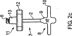
図2a−eは、本発明の別の実施形態による装置(7)を示す。この図は、図示のみの目的で装置の見込まれる寸法を示しており、装置の寸法はそれらに限定されるものではない。装置(7)は、近位端部(3)及び遠位端部(4)を有するドライブシャフト(2)を備える。近位端部(3)は、胴体部(9)及びクロスバー(10)を含むハンドル(8)を備える。ハンドル(8)は、図1a−hに記載される突出部(5)に装着される。ハンドルは、使用者がドライブシャフト(2)の近位端部(3)にトルクを加えることを可能にする。ドライブシャフト(2)の遠位端部(4)は、カム(6)を備える。カム(6)は、トルクがハンドル(8)を介してドライブシャフト(2)に加えられるとき、カム(6)がドライブシャフト(2)の軸と実質的に平行な方向で作動するように配置されている。 Figures 2a-e show a device (7) according to another embodiment of the invention. This figure shows possible dimensions of the device for illustration purposes only, and the dimensions of the device are not limited thereto. The device (7) comprises a drive shaft (2) having a proximal end (3) and a distal end (4). The proximal end (3) comprises a handle (8) that includes a body (9) and a crossbar (10). The handle (8) is attached to the protrusion (5) described in FIGS. 1a-h. The handle allows the user to apply torque to the proximal end (3) of the drive shaft (2). The distal end (4) of the drive shaft (2) comprises a cam (6). The cam (6) is arranged such that when torque is applied to the drive shaft (2) via the handle (8), the cam (6) operates in a direction substantially parallel to the axis of the drive shaft (2). Has been.
また、装置(7)は、第一部(12)及び第二部(13)を有する胴体部(11)を備える。胴体部(11)は、図3a−dにより詳細に示される。第一部(12)の直径は、第二部(13)の直径よりも大きい。第一部(12)及び第二部(13)は、それらの中心点が同軸となるように位置合わせされており、断面(図2a−c、図3b)で見たとき、胴体部は実質的にT型をしている。第一部(12)は、第一部(12)の外周を囲んで等距離に配置される4つの掴み部(15)を有する。第二部(13)はテーパーを付けられており、テーパーを付けられたスリーブと係合することができる。 The device (7) also comprises a body part (11) having a first part (12) and a second part (13). The torso part (11) is shown in more detail in FIGS. 3a-d. The diameter of the first part (12) is larger than the diameter of the second part (13). The first part (12) and the second part (13) are aligned so that their center points are coaxial, and when viewed in cross section (FIGS. 2a-c and 3b), the body part is substantially T-shaped. The first part (12) has four grips (15) that are arranged equidistantly around the outer periphery of the first part (12). The second part (13) is tapered and can engage with a tapered sleeve.
図3dに示されるように、穴(14)は、第一部(12)及び第二部(13)の両方を通って延在する。図2a、図2c、図3a、図3c、及び図3dから、穴(14)の中心軸が胴体部(11)の主軸からずれていることを理解でき、ドライブシャフト(2)の回転は、胴体部(11)に対するカム(6)の偏心した動きをもたらす。これは、図4a、図4bに図示される。図4a、図4bに示されるように、ドライブシャフトの回転(この実施形態においては時計方向)は、胴体部(11)における第二部(13)の範囲内からY方向に外れてカム(6)を動かす。図5に示されるように、ドライブシャフト(2)及びカム(6)は、ドライブシャフト(2)の軸と平行なZ方向に、平行移動する事ができる。 As shown in FIG. 3d, the hole (14) extends through both the first part (12) and the second part (13). 2a, 2c, 3a, 3c and 3d, it can be seen that the central axis of the hole (14) is offset from the main axis of the body (11), and the rotation of the drive shaft (2) is An eccentric movement of the cam (6) relative to the body (11) is brought about. This is illustrated in FIGS. 4a and 4b. As shown in FIGS. 4a and 4b, the rotation of the drive shaft (clockwise in this embodiment) is deviated in the Y direction from the range of the second portion (13) in the body portion (11), and the cam (6 ). As shown in FIG. 5, the drive shaft (2) and the cam (6) can be translated in the Z direction parallel to the axis of the drive shaft (2).
図6は、挿入されたスリーブ(16)を有する、インプラントヘッド(17)の断面を示す。図6に示されるように、スリーブ(16)の先端面(19)とインプラントヘッド(17)の内面(20)との間に、凹み空間(18)がある。凹み空間(18)は、カム(6)を受ける。凹み空間(18)の空間サイズは、1mm又はそれ以上であっても良い。凹み空間(18)の空間サイズは、2mm〜10mmであっても良い。通常、凹み空間(18)の空間サイズは、およそ2mmである。 FIG. 6 shows a cross section of an implant head (17) with an inserted sleeve (16). As shown in FIG. 6, there is a recessed space (18) between the distal face (19) of the sleeve (16) and the inner face (20) of the implant head (17). The recessed space (18) receives the cam (6). The space size of the recessed space (18) may be 1 mm or more. The space size of the recessed space (18) may be 2 mm to 10 mm. Usually, the space size of the recessed space (18) is approximately 2 mm.
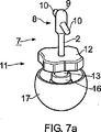
図7a−cは、インプラントヘッド(17)と共に使われる、図2a−eに記載される装置(7)を示す。装置(7)の遠位端部(4)は、スリーブ(16)の後端部を通ってインプラント組立品内に通され、遠位端部(4)が、スリーブの先端面(19)とインプラントヘッド(17)の内面(20)との間(図7a及び図6に示される)の凹み空間(18)内部に挿入されるまで、前進することが可能である。胴体部(11)の第二部(13)はスリーブ(16)中に位置し、その結果、スリーブ(16)において胴体部(11)を中心出しする。 Figures 7a-c show the device (7) described in Figures 2a-e for use with an implant head (17). The distal end (4) of the device (7) is passed through the rear end of the sleeve (16) and into the implant assembly, with the distal end (4) being connected to the sleeve tip surface (19). Advancement is possible until inserted into the recessed space (18) between the inner surface (20) of the implant head (17) (shown in FIGS. 7a and 6). The second part (13) of the body part (11) is located in the sleeve (16), so that the body part (11) is centered in the sleeve (16).
図7bに示されるように、トルクがハンドル(8)に加えられ、よってドライブシャフト(2)が回転する。図4a、図4bから、ドライブシャフト(2)のそのような回転が、胴体部(11)の第二部(13)の範囲内からY方向に外れてカム(6)を動かす。結果として、カム(6)は凹み空間(18)に移動し、カム(6)の先端部が、スリーブ(16)の先端面(19)及びインプラントヘッド(17)の内面(20)(図6参照)と係合する。ドライブシャフト(2)及びカム(6)の回転が続くとき、カム(6)は、ドライブシャフト(2)の軸と実質的に平行な方向(図5におけるZ方向)に作用し、それがスリーブ(16)とインプラントヘッド(17)とを強制的に引き離す。(図7c参照) As shown in FIG. 7b, torque is applied to the handle (8), thus rotating the drive shaft (2). 4a, 4b, such rotation of the drive shaft (2) deviates in the Y direction from within the range of the second part (13) of the body part (11) and moves the cam (6). As a result, the cam (6) moves into the recessed space (18), and the distal end of the cam (6) moves the distal end surface (19) of the sleeve (16) and the inner surface (20) of the implant head (17) (FIG. 6). Engaging). When the drive shaft (2) and the cam (6) continue to rotate, the cam (6) acts in a direction substantially parallel to the axis of the drive shaft (2) (Z direction in FIG. 5), which is the sleeve. (16) and the implant head (17) are forcibly pulled apart. (See Figure 7c)
ドライブシャフト(2)/カム(6)は、プラスチックで作られても良い。好ましくは、ドライブシャフト(2)/カム(6)は、金属で作られる。金属は、アルミニウム、チタニウム、ステンレス鋼、又は合金であっても良い。好ましくは、金属はステンレス鋼である。 The drive shaft (2) / cam (6) may be made of plastic. Preferably, the drive shaft (2) / cam (6) is made of metal. The metal may be aluminum, titanium, stainless steel, or an alloy. Preferably, the metal is stainless steel.
ハンドル(8)は、プラスチックで作られても良い。好ましくは、ハンドル(8)は、金属で作られる。金属は、アルミニウム、チタニウム、ステンレス鋼、又は合金であっても良い。好ましくは、金属はステンレス鋼である。 The handle (8) may be made of plastic. Preferably, the handle (8) is made of metal. The metal may be aluminum, titanium, stainless steel, or an alloy. Preferably, the metal is stainless steel.
胴体部(11)は、金属で作られても良い。金属は、アルミニウム、チタニウム、ステンレス鋼、又は合金であっても良い。好ましくは、胴体部(11)は、プラスチックで作られる。好ましくは、プラスチックはポリアセタールである。 The body part (11) may be made of metal. The metal may be aluminum, titanium, stainless steel, or an alloy. Preferably, the body part (11) is made of plastic. Preferably, the plastic is polyacetal.
1 装置
10 クロスバー
11 胴体部
12 第一部
13 第二部
14 穴
15 掴み部
16 スリーブ
17 インプラントヘッド
18 凹み空間
19 先端面
2 ドライブシャフト
20 内面
3 近位端部
4 遠位端部
5 突出部
6 カム
7 装置
8 ハンドル
9 胴体部
DESCRIPTION OF SYMBOLS 1
Claims (21)
前記カムが前記スリーブの先端面及び前記インプラントヘッドの内面と係合するように、前記スリーブの先端面と前記インプラントヘッドの内面との間にある凹み空間内に前記遠位端部を挿入するステップと、
前記カムが回転し、その結果、前記スリーブと前記インプラントヘッドとが強制的に引き離されるように、前記近位端部を介して前記ドライブシャフトにトルクを加えるステップと、を備えるスリーブをインプラントヘッドから分離する方法。A drive shaft having a proximal end and a distal end, the distal end having a cam, wherein the cam is torqued to the drive shaft through the proximal end; Providing an apparatus wherein the cam is arranged to act in a direction substantially parallel to an axis of the drive shaft;
Inserting the distal end into a recessed space between the distal end surface of the sleeve and the inner surface of the implant head such that the cam engages the distal end surface of the sleeve and the inner surface of the implant head. When,
Applying a torque to the drive shaft through the proximal end so that the cam rotates so that the sleeve and the implant head are forcibly separated from the implant head. How to separate.
Applications Claiming Priority (3)
| Application Number | Priority Date | Filing Date | Title |
|---|---|---|---|
| GBGB0613359.9A GB0613359D0 (en) | 2006-07-05 | 2006-07-05 | Separation device |
| GB0613359.9 | 2006-07-05 | ||
| PCT/GB2007/002489 WO2008003957A2 (en) | 2006-07-05 | 2007-07-04 | Separation device |
Publications (2)
| Publication Number | Publication Date |
|---|---|
| JP2009542273A JP2009542273A (en) | 2009-12-03 |
| JP5059857B2 true JP5059857B2 (en) | 2012-10-31 |
Family
ID=36926504
Family Applications (1)
| Application Number | Title | Priority Date | Filing Date |
|---|---|---|---|
| JP2009517422A Expired - Fee Related JP5059857B2 (en) | 2006-07-05 | 2007-07-04 | Separation device |
Country Status (10)
| Country | Link |
|---|---|
| US (1) | US9056021B2 (en) |
| EP (1) | EP2043564B1 (en) |
| JP (1) | JP5059857B2 (en) |
| CN (1) | CN101489505B (en) |
| AT (1) | ATE537787T1 (en) |
| AU (1) | AU2007270930B2 (en) |
| CA (1) | CA2656348A1 (en) |
| ES (1) | ES2379398T3 (en) |
| GB (1) | GB0613359D0 (en) |
| WO (1) | WO2008003957A2 (en) |
Family Cites Families (13)
| Publication number | Priority date | Publication date | Assignee | Title |
|---|---|---|---|---|
| JPS5044637Y1 (en) * | 1970-12-29 | 1975-12-18 | ||
| JPS604706Y2 (en) * | 1980-09-06 | 1985-02-12 | 富士重工業株式会社 | piston pin removal tool |
| JPS58126180U (en) * | 1982-02-19 | 1983-08-27 | 日東電工株式会社 | Tubular membrane module adapter extraction jig |
| US4787907A (en) * | 1987-02-03 | 1988-11-29 | Techmedica, Inc. | Morse taper |
| US5362311A (en) * | 1990-01-05 | 1994-11-08 | Kyocera Corporation | Artificial hip joint |
| US5116339A (en) * | 1990-07-11 | 1992-05-26 | Glock Steven R | Acetabular cup installation tool and method of installing an acetabular cup |
| JP3645326B2 (en) * | 1995-09-27 | 2005-05-11 | 豊田鉄工株式会社 | Extraction tool for press-fitting bush |
| US6132469A (en) * | 1997-11-07 | 2000-10-17 | Biomet, Inc. | Acetabular liner extractor |
| DE19833791A1 (en) * | 1998-07-21 | 2000-01-27 | Merete Management Gmbh | Tool for fitting or removing ball in joint prosthesis |
| JP2002370179A (en) * | 2001-06-15 | 2002-12-24 | Ryouke Tekko:Kk | Removing apparatus for parts |
| DE20114835U1 (en) * | 2001-09-03 | 2001-12-06 | Merete Medical Gmbh | Adapter and puller for hip joints |
| US7024972B2 (en) * | 2003-05-27 | 2006-04-11 | Wj Technologies, Inc. | Tool for removing and tightening screw-on drains |
| US7927376B2 (en) * | 2005-06-30 | 2011-04-19 | Depuy Products, Inc. | Expandable acetabular liner extraction device, cup assembly and associated method |
-
2006
- 2006-07-05 GB GBGB0613359.9A patent/GB0613359D0/en not_active Ceased
-
2007
- 2007-07-04 AT AT07733454T patent/ATE537787T1/en active
- 2007-07-04 JP JP2009517422A patent/JP5059857B2/en not_active Expired - Fee Related
- 2007-07-04 ES ES07733454T patent/ES2379398T3/en active Active
- 2007-07-04 US US12/307,419 patent/US9056021B2/en active Active
- 2007-07-04 AU AU2007270930A patent/AU2007270930B2/en not_active Ceased
- 2007-07-04 CA CA002656348A patent/CA2656348A1/en not_active Abandoned
- 2007-07-04 EP EP07733454A patent/EP2043564B1/en not_active Not-in-force
- 2007-07-04 WO PCT/GB2007/002489 patent/WO2008003957A2/en active Application Filing
- 2007-07-04 CN CN2007800255244A patent/CN101489505B/en not_active Expired - Fee Related
Also Published As
| Publication number | Publication date |
|---|---|
| GB0613359D0 (en) | 2006-08-16 |
| WO2008003957A2 (en) | 2008-01-10 |
| AU2007270930B2 (en) | 2014-01-16 |
| ES2379398T3 (en) | 2012-04-25 |
| EP2043564A2 (en) | 2009-04-08 |
| CN101489505B (en) | 2012-03-21 |
| US9056021B2 (en) | 2015-06-16 |
| ATE537787T1 (en) | 2012-01-15 |
| WO2008003957A3 (en) | 2008-02-21 |
| US20090281547A1 (en) | 2009-11-12 |
| EP2043564B1 (en) | 2011-12-21 |
| AU2007270930A1 (en) | 2008-01-10 |
| CN101489505A (en) | 2009-07-22 |
| JP2009542273A (en) | 2009-12-03 |
| CA2656348A1 (en) | 2008-01-10 |
Similar Documents
| Publication | Publication Date | Title |
|---|---|---|
| JP7041629B2 (en) | Holder for surface reconstruction head implants | |
| US6436103B1 (en) | Drill guide and plate attachment mechanism for orthopedic plating | |
| US9763675B2 (en) | Angled instrument assembly | |
| US20040215108A1 (en) | Side attaching guidwire torque device | |
| JP5722338B2 (en) | Screw delivery system | |
| JP5472517B1 (en) | Medical screw and jig for removing medical screw | |
| EP2974680B1 (en) | Medical screw | |
| US20060116680A1 (en) | Extractor for a bone connection element | |
| KR102231234B1 (en) | Remover for polygon screw for sergery | |
| EP3328319B1 (en) | Drill guide for acetabular cup fasteners | |
| JP5059857B2 (en) | Separation device | |
| JP2003265492A (en) | Operation tool for implant | |
| JP4874636B2 (en) | Insertion device and extraction device for insert of bone connecting element and insert | |
| JP6235331B2 (en) | Hip surgery instrument | |
| JP6525842B2 (en) | Surgical grasper | |
| KR100923275B1 (en) | Dental instrument for cutting bone | |
| JP2019141138A (en) | Fractured implant body removing tool and removing method | |
| JP5162722B1 (en) | Medical nut | |
| US20220134518A1 (en) | Power drive adapter tool | |
| JP2002291762A (en) | Implant set screw operation appliance and its using method |
Legal Events
| Date | Code | Title | Description |
|---|---|---|---|
| A621 | Written request for application examination |
Free format text: JAPANESE INTERMEDIATE CODE: A621 Effective date: 20100611 |
|
| A977 | Report on retrieval |
Free format text: JAPANESE INTERMEDIATE CODE: A971007 Effective date: 20120622 |
|
| TRDD | Decision of grant or rejection written | ||
| A01 | Written decision to grant a patent or to grant a registration (utility model) |
Free format text: JAPANESE INTERMEDIATE CODE: A01 Effective date: 20120703 |
|
| A01 | Written decision to grant a patent or to grant a registration (utility model) |
Free format text: JAPANESE INTERMEDIATE CODE: A01 |
|
| A61 | First payment of annual fees (during grant procedure) |
Free format text: JAPANESE INTERMEDIATE CODE: A61 Effective date: 20120802 |
|
| FPAY | Renewal fee payment (event date is renewal date of database) |
Free format text: PAYMENT UNTIL: 20150810 Year of fee payment: 3 |
|
| R150 | Certificate of patent or registration of utility model |
Ref document number: 5059857 Country of ref document: JP Free format text: JAPANESE INTERMEDIATE CODE: R150 Free format text: JAPANESE INTERMEDIATE CODE: R150 |
|
| R250 | Receipt of annual fees |
Free format text: JAPANESE INTERMEDIATE CODE: R250 |
|
| R250 | Receipt of annual fees |
Free format text: JAPANESE INTERMEDIATE CODE: R250 |
|
| R250 | Receipt of annual fees |
Free format text: JAPANESE INTERMEDIATE CODE: R250 |
|
| R250 | Receipt of annual fees |
Free format text: JAPANESE INTERMEDIATE CODE: R250 |
|
| S531 | Written request for registration of change of domicile |
Free format text: JAPANESE INTERMEDIATE CODE: R313531 |
|
| R350 | Written notification of registration of transfer |
Free format text: JAPANESE INTERMEDIATE CODE: R350 |
|
| R250 | Receipt of annual fees |
Free format text: JAPANESE INTERMEDIATE CODE: R250 |
|
| R250 | Receipt of annual fees |
Free format text: JAPANESE INTERMEDIATE CODE: R250 |
|
| LAPS | Cancellation because of no payment of annual fees |