EP2043091B1 - Optical information reproducing method and apparatus, and optical information recording medium - Google Patents
Optical information reproducing method and apparatus, and optical information recording medium Download PDFInfo
- Publication number
- EP2043091B1 EP2043091B1 EP08016802.4A EP08016802A EP2043091B1 EP 2043091 B1 EP2043091 B1 EP 2043091B1 EP 08016802 A EP08016802 A EP 08016802A EP 2043091 B1 EP2043091 B1 EP 2043091B1
- Authority
- EP
- European Patent Office
- Prior art keywords
- readout signal
- correction
- readout
- fluctuation
- correction coefficients
- Prior art date
- Legal status (The legal status is an assumption and is not a legal conclusion. Google has not performed a legal analysis and makes no representation as to the accuracy of the status listed.)
- Not-in-force
Links
Images


Classifications
-
- G—PHYSICS
- G11—INFORMATION STORAGE
- G11B—INFORMATION STORAGE BASED ON RELATIVE MOVEMENT BETWEEN RECORD CARRIER AND TRANSDUCER
- G11B7/00—Recording or reproducing by optical means, e.g. recording using a thermal beam of optical radiation by modifying optical properties or the physical structure, reproducing using an optical beam at lower power by sensing optical properties; Record carriers therefor
- G11B7/004—Recording, reproducing or erasing methods; Read, write or erase circuits therefor
- G11B7/005—Reproducing
-
- G—PHYSICS
- G11—INFORMATION STORAGE
- G11B—INFORMATION STORAGE BASED ON RELATIVE MOVEMENT BETWEEN RECORD CARRIER AND TRANSDUCER
- G11B20/00—Signal processing not specific to the method of recording or reproducing; Circuits therefor
- G11B20/10—Digital recording or reproducing
- G11B20/10009—Improvement or modification of read or write signals
- G11B20/10018—Improvement or modification of read or write signals analog processing for digital recording or reproduction
- G11B20/10027—Improvement or modification of read or write signals analog processing for digital recording or reproduction adjusting the signal strength during recording or reproduction, e.g. variable gain amplifiers
-
- G—PHYSICS
- G11—INFORMATION STORAGE
- G11B—INFORMATION STORAGE BASED ON RELATIVE MOVEMENT BETWEEN RECORD CARRIER AND TRANSDUCER
- G11B20/00—Signal processing not specific to the method of recording or reproducing; Circuits therefor
- G11B20/10—Digital recording or reproducing
- G11B20/10009—Improvement or modification of read or write signals
- G11B20/10046—Improvement or modification of read or write signals filtering or equalising, e.g. setting the tap weights of an FIR filter
- G11B20/10055—Improvement or modification of read or write signals filtering or equalising, e.g. setting the tap weights of an FIR filter using partial response filtering when writing the signal to the medium or reading it therefrom
-
- G—PHYSICS
- G11—INFORMATION STORAGE
- G11B—INFORMATION STORAGE BASED ON RELATIVE MOVEMENT BETWEEN RECORD CARRIER AND TRANSDUCER
- G11B20/00—Signal processing not specific to the method of recording or reproducing; Circuits therefor
- G11B20/10—Digital recording or reproducing
- G11B20/10009—Improvement or modification of read or write signals
- G11B20/10268—Improvement or modification of read or write signals bit detection or demodulation methods
- G11B20/10287—Improvement or modification of read or write signals bit detection or demodulation methods using probabilistic methods, e.g. maximum likelihood detectors
- G11B20/10296—Improvement or modification of read or write signals bit detection or demodulation methods using probabilistic methods, e.g. maximum likelihood detectors using the Viterbi algorithm
-
- G—PHYSICS
- G11—INFORMATION STORAGE
- G11B—INFORMATION STORAGE BASED ON RELATIVE MOVEMENT BETWEEN RECORD CARRIER AND TRANSDUCER
- G11B20/00—Signal processing not specific to the method of recording or reproducing; Circuits therefor
- G11B20/10—Digital recording or reproducing
- G11B20/10009—Improvement or modification of read or write signals
- G11B20/10305—Improvement or modification of read or write signals signal quality assessment
- G11B20/10398—Improvement or modification of read or write signals signal quality assessment jitter, timing deviations or phase and frequency errors
- G11B20/10425—Improvement or modification of read or write signals signal quality assessment jitter, timing deviations or phase and frequency errors by counting out-of-lock events of a PLL
-
- G—PHYSICS
- G11—INFORMATION STORAGE
- G11B—INFORMATION STORAGE BASED ON RELATIVE MOVEMENT BETWEEN RECORD CARRIER AND TRANSDUCER
- G11B20/00—Signal processing not specific to the method of recording or reproducing; Circuits therefor
- G11B20/22—Signal processing not specific to the method of recording or reproducing; Circuits therefor for reducing distortions
-
- G—PHYSICS
- G11—INFORMATION STORAGE
- G11B—INFORMATION STORAGE BASED ON RELATIVE MOVEMENT BETWEEN RECORD CARRIER AND TRANSDUCER
- G11B7/00—Recording or reproducing by optical means, e.g. recording using a thermal beam of optical radiation by modifying optical properties or the physical structure, reproducing using an optical beam at lower power by sensing optical properties; Record carriers therefor
- G11B7/007—Arrangement of the information on the record carrier, e.g. form of tracks, actual track shape, e.g. wobbled, or cross-section, e.g. v-shaped; Sequential information structures, e.g. sectoring or header formats within a track
- G11B7/00736—Auxiliary data, e.g. lead-in, lead-out, Power Calibration Area [PCA], Burst Cutting Area [BCA], control information
-
- G—PHYSICS
- G11—INFORMATION STORAGE
- G11B—INFORMATION STORAGE BASED ON RELATIVE MOVEMENT BETWEEN RECORD CARRIER AND TRANSDUCER
- G11B7/00—Recording or reproducing by optical means, e.g. recording using a thermal beam of optical radiation by modifying optical properties or the physical structure, reproducing using an optical beam at lower power by sensing optical properties; Record carriers therefor
- G11B2007/0003—Recording, reproducing or erasing systems characterised by the structure or type of the carrier
- G11B2007/0009—Recording, reproducing or erasing systems characterised by the structure or type of the carrier for carriers having data stored in three dimensions, e.g. volume storage
- G11B2007/0013—Recording, reproducing or erasing systems characterised by the structure or type of the carrier for carriers having data stored in three dimensions, e.g. volume storage for carriers having multiple discrete layers
-
- G—PHYSICS
- G11—INFORMATION STORAGE
- G11B—INFORMATION STORAGE BASED ON RELATIVE MOVEMENT BETWEEN RECORD CARRIER AND TRANSDUCER
- G11B2220/00—Record carriers by type
- G11B2220/20—Disc-shaped record carriers
- G11B2220/23—Disc-shaped record carriers characterised in that the disc has a specific layer structure
- G11B2220/235—Multilayer discs, i.e. multiple recording layers accessed from the same side
-
- G—PHYSICS
- G11—INFORMATION STORAGE
- G11B—INFORMATION STORAGE BASED ON RELATIVE MOVEMENT BETWEEN RECORD CARRIER AND TRANSDUCER
- G11B2220/00—Record carriers by type
- G11B2220/20—Disc-shaped record carriers
- G11B2220/25—Disc-shaped record carriers characterised in that the disc is based on a specific recording technology
- G11B2220/2537—Optical discs
Definitions
- the present invention relates to an optical information reproducing apparatus and method for recording or reproducing information on an optical recording medium.
- Fig. 2 illustrates in schematic form a cross-sectional configuration of a heretofore known multilayer optical disc and the principle of selective reproduction of information on information-recordable or information-bearing information layers.
- Fig. 2 shows an optical head, only a part of the objective lens.
- an information recording medium includes plural information layers, that is, a total of four information layers consisting of a first information layer 211, a second information layer 212, a third information layer 213 and a fourth information layer 214, and thus will be hereinafter called a "four-layer medium.”
- access to recorded information on the third information layer 213, for example involves controlling the position of an objective lens 30, thereby positioning a light spot 32 on the third information layer 213.
- a converging ray 31 is focused through the objective lens 30 and passes through the translucent first and second information layers 211 and 212 before reaching the third information layer 213.
- the converging ray 31 does not act to resolve and thereby reproduce recorded information on the translucent first and second information layers 211 and 212 since a beam diameter of the converging rays 31 on the first and second information layers is sufficiently larger than the diameter of the light spot 32 on the third information layer 213. In this manner, reproduction of information on the third information layer located on the farther side, as viewed from a light source, than the first and second information layers is achieved without being affected by the first and second information layers.
- the reproduction of information on the fourth information layer 214 involves controlling the position of the objective lens 30, thereby positioning the light spot 32 on the fourth information layer 214.
- the beam diameter on the layer (hereinafter called an "adjacent layer") adjacent to the layer targeted for reproduction is given by the following equation: L * NA / 1 - NA ⁇ ⁇ 2 ⁇ 1 / 2 .
- Japanese Patent Application Publication No. Hei 11-016208 gives a disclosure as to how to design the reflectance and transmittance of the information layers of the multilayer optical disc as mentioned above.
- a multilayer information recording medium having a stacked construction of three or more information layers is designed such that R n , a n and R n-1 can satisfy the relationship defined by the following expression: R n - 1 ⁇ R n ⁇ 1 - a n - 1 - R n - 1 ⁇ ⁇ 2
- R n and a n denote the reflectance and absorbance, respectively, of the n -th
- R n -1 denotes the reflectance of the ( n -1)th information layer. Since (1- a n -1 - R n -1 ) indicates the transmittance of the ( n -1)th layer, the above expression determines that the quantity of light reflected from the ( n -1)th layer will be approximately equal to the quantity of light that travels through the ( n -1)th layer, bounces off the n-th layer and further travels back through the ( n -1)th layer toward the optical head.
- the medium is designed such that all layers have approximately equal effective reflectance for light to exit from the optical head to the layers and return to the optical head.
- the medium is designed so that a layer located on the far side, as viewed from the light incoming side, has high reflectance to thereby compensate attenuation of light intensity caused by reflection and absorption by a layer located on the near side.
- Japanese Patent Application Publication No. 2005-38463 discloses that the information layer located farther away from the light entrance surface has greater layer thickness, so that the quantities of light reflected from the information layers become approximately equal, and that the refractive index of a disc sheet is set substantially equal to that of a bonding layer.
- a design method for the medium of multilayer structure as mentioned above takes into account the effect of the attenuation of light through a near-side layer located between a target layer for recording or reproduction and the light incident surface of the medium, but does not take into account the influence of repeated reflections of light, or equivalently, what is termed as multiple reflections of light, in the near-side layer.
- Description will be given with reference to Fig. 11 with regard to a situation where multiple-reflected light causes a problem. Assume that the target layer for reproduction is the n -th layer and that the n -th layer is irradiated at the top with light, as shown in Fig. 11 .
- the light reflected from the ( n -1)th layer immediately preceding the target layer travels as unwanted light to the upper side (nearer side to the light source) of the ( n -2)th layer. Then, the unwanted light reflected from the upper side of the ( n -2)th layer again bounces off the ( n -1)th layer to travel back toward the optical head along substantially the same path as that of reflected light from the n-th layer, resulting in the occurrence of crosstalk of great magnitude.
- the unwanted light returning to the optical head as mentioned above presents a large problem.
- the unwanted light converges on the ( n -2)th layer to form a ghost spot, and thus permits optical resolution of information on the ( n -2)th layer.
- the unwanted light causes unwanted signals having a band overlapping the band of general readout signals, and even worse the unwanted signals are inseparable from the general signals.
- the returned light of the unwanted light travels back to the optical head along substantially the same path as that of the reflected light from the n -th layer and thus likewise travels through the optical head along the same optical path.
- both kinds of light are brought into complete coincidence on a detector.
- the incapability of light separation on the detector also constitutes a factor that renders difficult the quantitative evaluation of the amount of crosstalk caused by the unwanted light.
- the spacer layers having the same optical constant are used to vary the thickness and thereby vary the distance between the layers.
- this approach has the problem that the influence of the unwanted light is likely to remain because a mere difference on the order of 2 ⁇ m in the distance between the layers results in a small difference between the size of the light spot of the unwanted light and that of the originally desired light spot.
- a deviation on the order of only 1 ⁇ m of the distance between the layers due to manufacturing variations or the like may cause a sharp increase in the crosstalk due to the unwanted light.
- there is a need to manufacture a very-high-precision medium with suppressed variations which in turn leads to an increase in the cost of manufacture of the medium.
- Still another problem is that the distance between the layers has to be greater than that for a general two-layer medium in order to achieve a low margin of interlayer crosstalk, which in turn makes it difficult to increase the number of layers.
- the medium is contrived to eliminate the crosstalk due to the unwanted light, because it is difficult to separate signal light from the crosstalk due to the unwanted light by use of the detector, as mentioned above.
- a reproducing apparatus and method adapted to eliminate distortion of the readout signal due to the interlayer crosstalk are disclosed for example in Japanese Patent Application Publication No. 2006-120291 (hereinafter referred to as Patent Literature 5) as a method for overcoming the crosstalk by use of the apparatus.
- the method involves sampling a top envelope signal of the readout signal, and performing gain control on the readout signal containing DC components so that the top envelope signal can be substantially constant.
- An optical information reproducing method for reproducing information by irradiating a light beam onto a disc-shaped optical information recording medium having a plurality of information layers comprising the steps of:
- the present invention offers a solution to the foregoing problems by adopting a constitution as given in the appended claims.
- the magnitude of the interlayer crosstalk which is problematic for reproducing the information on a multilayer optical information recording medium, changes according to a distance between the information layers, a so-called interlayer distance.
- the interlayer distance depends not only on the physical thickness of the spacer layer interposed between the information layers, but also on the optical distance of the spacer layer.
- the optical distance of the spacer layer may change even with the substantially same physical thickness due to a partial difference in an optical constant of the spacer layer.
- the thickness of the spacer layer formed by spin coating varies around a track, the tendency of variation is substantially the same in a radial direction, and as a result, the tendency of variation in the readout signal caused by the interlayer crosstalk is likewise substantially the same in the radial direction. Accordingly, a variation level of the readout signal on a predetermined track is stored, the correction coefficient is calculated based on a predetermined set frequency so that the readout signal is substantially fixed, the readout signal in a preset area is calculated using the calculated correction coefficient, and thereby, the variation in the readout signal caused by the interlayer crosstalk is corrected. The capture of the readout signal for calculation of the correction coefficient is done at predetermined intervals in the radial direction of the optical information recording medium.
- the readout signal is substantially constant means that the readout signal fluctuates within a range of 5%. Fluctuations of the readout signal beyond the range of 5% cause a rise in error rate or an increase in jitter, thus leading to deterioration in the performance capability of reproduction. Preferably, therefore, the readout signal fluctuates within the range of 5%, and thus, the condition that the rate of fluctuation of the readout signal falls within the range of 5% is set as the condition for rendering the readout signal substantially constant.
- the correction coefficient is used for signal fluctuation correction within a preset radius (or equivalently, a distance from the center of a disc).
- the above-mentioned preset area may be the area within any one of the inner radius and outer radius of the track or alternatively the area around the track, provided that the area is a predetermined area containing the track bearing the readout signal captured for the calculation of the correction coefficient. Setting the area around the track enables achieving the advantageous effect of reducing the influence of the dependence of the thickness of the spacer layer upon the radius.
- the correction coefficient may be calculated from readout signals on plural adjacent tracks.
- the method may include calculating each correction coefficient of the readout signals on the plural adjacent tracks; averaging the plural correction coefficients; and performing computing on the readout signal by use of the average correction coefficient, thereby correcting the fluctuation of the readout signal.
- the method may include producing a virtual readout signal by averaging the readout signals on the plural adjacent tracks; and calculating the correction coefficient from the virtual readout signal.
- the correction coefficient for rendering the readout signal fluctuation substantially constant will conveniently be calculated by setting constant a frequency for the correction coefficient.
- the correction coefficient be calculated by varying a set frequency for the correction coefficient according to the magnitude of fluctuation of the readout signal per unit time, such as by setting high frequency for the correction coefficient in an area of a round of track where the readout signal fluctuates greatly, while setting low frequency in an area where the readout signal does not fluctuate.
- the readout signal captured for calculation of the correction coefficient is the readout signal in an unrecorded area that does not bear information.
- the reason is as follows although the envelope signal is obtained on an information-bearing track, signal components such as 3T and 4T are not contained in an unrecorded track bearing no information, and therefore, the unrecorded track enables more precise sampling of fluctuation components due to the interlayer crosstalk.
- the stored correction coefficient is stored in conjunction with information such as a position on the disc (e.g., a radial position) in which then correction coefficient is calculated, and, for plural reproductions, the correction coefficient calculated and stored in advance is used for readout signal fluctuation correction.
- the readout signal on a round of disc may be used as a unit for the capture of the readout signal and the calculation of the correction coefficient.
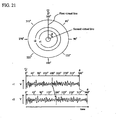
- reproduction time for the readout signal at an outer radius r2 is longer than that for the readout signal at an inner radius r1, as shown in Fig. 21 . If the thickness of the spacer layer formed by means of spin coating varies track by track, the trend of thickness variation and consequently, the trend of readout signal fluctuation caused by the interlayer crosstalk is substantially the same in the radial direction.
- the correction coefficient calculated at a 180-degree position at the radius r1 be likewise used at the 180-degree position at the radius r2 (in this instance, the reproduction times from the given position (e.g., a 0-degree position shown in Fig. 21 ) at the radius r1 and the radius r2 are different).
- the correction coefficient is stored in correspondence with the angle from the given position (marked with a triangle in Fig. 21 ), or equivalently, the circumferential position, rather than in correspondence with the reproduction time.
- an angle ⁇ between first and second virtual lines, starting at a point on the first virtual line and ending on the second virtual line, as shown in Fig. 21 is brought into correspondence with the correction coefficients in circumferential positions.
- the circumferential position will conveniently be stored utilizing as a trigger a disc rotation synchronizing signal such as a spindle index.
- a table containing the correspondence between the correction coefficient and circumferential positional information is shown as an example of a method for calculating the correction coefficient.
- a drive may store the correction coefficient in correspondence with the circumferential position (i.e., the angle ⁇ ) from the spindle index.
- the correction coefficient is calculated by the above operation expression, it is to be understood that the equation for the calculation of the correction coefficient, as given herein, is only illustrative and is not intended to limit the scope of the invention.
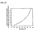
- the correction of the fluctuation of the readout signal may include calculating a modulation of the readout signal targeted for correction, and correcting fluctuations of top and bottom envelopes of the readout signal targeted for correction, using a correction coefficient conversion table prepared beforehand within the drive, as shown in Fig. 20 .
- the correction coefficient conversion table is the table in which the relationship shown in Fig. 22 takes numerical form. For example, if correction is provided to the readout signal having a modulation of 52%, the amount of fluctuation of the bottom envelope is of magnitude 1.44 times that of the amount of fluctuation of the top envelope. Utilization of this relationship is effective for time reduction because of eliminating the need to calculate and store the respective correction coefficients for the top and bottom envelopes.
- an approach may be adopted which involves capturing the respective fluctuations of the top and bottom envelopes and calculating and storing the respective correction coefficients therefor. At the occurrence of some warpage in an optical head, the relationship between the respective fluctuations of top and bottom envelopes may differ from that shown in Fig. 22 . Accordingly, the use of the respective correction coefficients calculated for the top and bottom envelopes may possibly achieve more accurate correction.
- the calculation of the correction coefficient may include detection of readout signal fluctuation, using a readout signal processing circuit included in the drive beforehand.
- the readout signal processing circuit is any one of an AGC (automatic gain control) circuit, an automatic slicer circuit, a PRML (partial response most-likely) circuit, and the like. These circuits have the function of suppressing the readout signal fluctuation.
- a reproducing circuit in which the AGC circuit is used for the detection of the readout signal fluctuation is shown as an example in Fig. 16 .
- a high-pass filter HPF
- HPF high-pass filter
- EQ equalizer
- the AGC performs variable gain control so that the readout signal has predetermined amplitude.
- the AGC detects the envelope of the readout signal, and feeds the detected envelope signal as a control signal back to the variable gain of an amplitude amplifier to thereby maintain the amplitude of the readout signal constant.
- a control band of the AGC is several kilohertz for a general readout signal, and thus the detected envelope signal contains components within several kilohertz of the readout signal that fluctuates due to the interlayer crosstalk. Then, the above-mentioned correction coefficient can be obtained from this signal.
- a correction coefficient calculation circuit calculates the correction coefficient from the detected envelope signal, and a correction coefficient recording circuit holds the calculated correction coefficient. Also, the automatic slicer performs binarization on the readout signal controlled in amplitude by the AGC.
- the automatic slicer of duty feedback type performs variable control on a binary decision level so that a mark portion and a space portion of the readout signal are equal in duty ratio.
- a PLL phase-locked loop
- the automatic slicer circuit may be used for the calculation of the correction coefficient, as in the case of the AGC circuit.
- a binary decision level signal from the automatic slicer is used for the calculation of the correction coefficient.
- the automatic slicer circuit of the duty feedback type performs variable control on the binary decision level so that the mark portion and the space portion of the readout signal are equal in duty ratio, to thereby accommodate signal level fluctuations or asymmetric variations during the binarization of the readout signal.
- variations in the binary decision level can be utilized for the calculation of the correction coefficient, as in the case of the AGC circuit mentioned above.
- the binary decision level is generated, for example, by integrating a difference signal between the binary signal and the inverted signal with respect to a predetermined time constant. Other flows of signal processing are the same as those in the processing blocks shown in Fig. 16 .
- the PRML circuit having the function of adaptive target correction causes a reference level (or a target level) for Viterbi decoding to follow the readout signal, by means of an algorithm for least squares, so as to minimize an equalization error or level jitter of the readout signal. Because of containing the readout signal fluctuation components caused by the interlayer crosstalk, target level fluctuation can be utilized for the calculation of the correction coefficient, as in the case of the above two examples.
- Fig. 18 shows an example of processing blocks having such a function. The flow of signal processing to the PLL is the same as those shown in Figs. 16 and 17 .
- the PRML generates binary reproduced data resultant from the binarization, from the readout signal sampled by the reference clock generated by the PLL, by means of an algorithm for Viterbi detection.
- the Viterbi detection uses past and current sample data to output the most likely data sequence as a reproduced data stream.
- the correction coefficient calculation circuit calculates the correction coefficients from a variation in the target level, and a correction coefficient storage circuit holds the calculated correction coefficient.
- an optical information reproducing apparatus for reproducing information by irradiating with a light beam an optical information recording medium having plural information layers, including: a means for capturing a readout signal reproduced by bringing the light beam into focus on one of the plural information layers; a means for storing the readout signal; a means for calculating a correction coefficient such that the readout signal is substantially constant; a means for storing the correction coefficient; and a means for performing computing on the readout signal and/or a different readout signal in the same information layer by use of the correction coefficient, thereby correcting fluctuation of the readout signal.
- the optical information reproducing apparatus includes a means for averaging plural correction coefficients obtained from readout signals on plural adjacent tracks; and a means for performing computing on the readout signal used for calculation of the correction coefficient and/or a different readout signal in the same information layer by use of the average correction coefficient, thereby correcting the fluctuation of the readout signal.
- the optical information reproducing apparatus of the present invention may include a means for averaging readout signals on plural adjacent tracks; a means for correcting a correction coefficient from a virtual readout signal resultant from the averaging; and a means for performing computing on the readout signal used for calculation of the correction coefficient and/or a different readout signal in the same information layer by use of the average correction coefficient, thereby correcting the fluctuation of the readout signal.
- the optical information reproducing apparatus of the present invention further includes a means for calculating a modulation of the readout signal; a correction coefficient conversion table for correction coefficient conversion of top and bottom envelopes, based on modulation information; a means for storing the correction coefficient conversion table; and a means for correcting fluctuations of the top and bottom envelopes of the readout signal, using the correction coefficient conversion table.
- Utilization of the correction coefficient conversion table for the readout signal correction is effective for time reduction because of eliminating the need to calculate and store the respective correction coefficients for the top and bottom envelopes
- the approach may be adopted which involves capturing the respective fluctuations of the top and bottom envelopes and calculating and storing the respective correction coefficients therefor.
- the approach of determining the respective correction coefficients for the top and bottom envelopes enables achievement of accurate correction, although taking time.
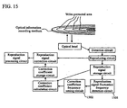
- An optical information recording medium suitable for the information reproducing method of the present invention having plural information layers, is characterized by including write-protected areas for readout signal fluctuation correction, which are disposed at predetermined intervals in the radial direction of the optical information recording medium.
- the write-protected areas for the readout signal fluctuation correction may be disposed at the same radius on two or more of the plural information layers at the predetermined intervals in the radial direction of the optical information recording medium.
- the disposition of the write-protected areas at the same radius has the advantage of being able to reduce the fluctuation components of the readout signal involved in recording.
- information such as an address of a write-protected track is written in a disc management area.
- the writing of the address of the write-protected track in the disc management area has the advantage of reducing the processing time required for the optical information reproducing apparatus to perform information reproducing, because of enabling the drive to make an instantaneous determination of a radial position or the like on the write-protected track.
- the present invention can achieve the optical information reproducing method and the optical information reproducing apparatus, capable of eliminating the influence of readout signal fluctuation even at the occurrence of the fluctuation in the readout signal caused by the interlayer crosstalk during reproduction on the optical information recording medium having the plural information layers, thereby enabling accurate restoration of information based on the readout signal as not affected by the influence of the interlayer crosstalk.
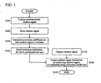
- Fig. 1 shows a process flow chart of an information reproducing method according to one embodiment of the present invention.
- a multilayer recording medium of 12 cm diameter having a stacked construction of three information layers is used, and reproduction is performed on the layer located farthest away from a laser irradiation side.
- correction coefficients are defined for each 1 mm, and the radius for calculating correction coefficient is set at intervals of 1 mm, for example, 24 mm, 25 mm, 26 mm, ..., and 57 mm. Description will be given here with regard to a readout signal correction method as implemented at the vicinity of a radius of 40 mm, as an example.
- a readout signal is captured at a radius of 40.0 mm (at step S101), and then stored (at step S102).
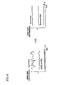
- Fig. 3 is a schematic diagram of the readout signal captured in an oscilloscope. Envelope signals of the readout signal are distorted under the influence of interlayer crosstalk, and thus, a reproduced result cannot be accurately restored as it is. Accordingly, a correction coefficient is calculated so that the readout signal is substantially constant (at step S103), and the correction coefficient is stored (at step S104). Specifically, as shown in Fig. 4 , the voltage values of the readout signal were measured at sampling points (marked with " ⁇ " in Fig.
- the ratio of the measured value to an ideal envelope under no signal fluctuation was calculated, and the reciprocal of the calculated ratio was set as the correction coefficient in a predetermined area.
- a range of 39.5 mm to 40.5 mm was defined as the predetermined area.
- the readout signal obtained at a radius of 40.1 mm was subjected to the correction using the correction coefficient calculated at a radius of 40 mm, to thereby form a good-quality readout signal with little fluctuation. Thus, the signal could be accurately restored.
- each correction coefficient was calculated for each radius from the innermost radius to the outermost radius as described above, and stored in memory.
- the correction coefficient calculated at a radius of 24 mm was used to correct a readout signal in a area of a radius of 23.5 mm to 24.5 mm
- the correction coefficient calculated at a radius of 25 mm was used to correct a readout signal in a area of a radius of 24.5 mm to 25.5 mm.
- each correction coefficient was calculated in units of a predetermined radius, and stored.
- the use of each correction coefficient for the readout signal correction enables a correction process in a shorter time, as compared to a method that involves evaluating and correcting the amount of readout signal fluctuation every time the readout signal is read.
- the present invention is characterized by learning the amount of readout signal fluctuation in units of the predetermined radius and using the learned amount of correction in units of the predetermined area.
- each correction coefficient is calculated in units of a radius of I mm, and the correction coefficient calculated at a radius of 40 mm is used for a area of a radius of 39.5 mm to 40.5 mm.
- a area of a radius of 40 to 41 mm or a area of a radius of 39 mm to 40 mm may be set as the area for which the correction coefficient is used, and any area will do, provided that the area contains a radius at which the readout signal captured for the calculation of the correction coefficient is present.
- the track for the calculation of the correction coefficient can be located at the midpoint of the area to thereby lessen the influence of the dependency of the readout signal fluctuation upon the radius, as is the case with the first embodiment.
- the area for which the correction coefficient is used may be narrowed to a area of a radius of 39.75 mm to 40.25 mm or be rather widened to a area of a radius of 39 mm to 41 mm.
- the narrowed range has the advantage of being able to lessen the influence of the dependency of the readout signal fluctuation upon the radius, while the widened range has the advantage of being able to reduce the time for the calculation of the correction coefficient and the memory capacity for storage of the correction coefficient
- the ratio between the envelope of the readout signal and the ideal envelope under no signal fluctuation is calculated, and the reciprocal of the calculated ratio is set as the correction coefficient; however, a difference between the readout signal voltage value and the ideal envelope voltage value may be set as the correction coefficient, as shown in Fig. 5 . Any correction coefficient will do, provided that the coefficient is correlated with the difference between the measured distortion-bearing readout signal and the ideal readout signal.
- information obtained for the readout signal correction may be used to suppress fluctuations in a tracking servo or the like.
- the correction coefficient is calculated from the readout signal on the information-bearing track to thereby suppress the readout signal fluctuation due to the interlayer crosstalk
- the correction coefficient may be calculated from a readout signal on a so-called unrecorded track that does not bear information. Since the unrecorded track bears no information, the main cause of the signal fluctuation is often the interlayer crosstalk. Thus, the use of the unrecorded track enables accurate sampling of signal fluctuation components due to the interlayer crosstalk.
- the readout signal correction coefficient was calculated, and was stored, in an unrecorded area disposed at a radius of 43.00 mm, in accordance with the process flow chart shown in Fig. 1 ; and a readout signal in a recorded area at a radius of 43.05 mm was subjected to correction using the stored correction coefficient mentioned above. As a result, a good readout signal with little fluctuation could be obtained.
- the correction coefficient is used to perform computing on the readout signal and thereby correct the readout signal fluctuation, and the amount of signal fluctuation is checked whether or not equal to or less than a predetermined amount (at step S706). This enables achieving the signal fluctuation correction with higher accuracy.
- the readout signal on only one predetermined track is used for calculation of the correction coefficient.
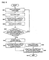
- description will be given with reference to Fig. 8 with regard to an instance where readout signals on plural tracks are used for calculation of correction coefficients.
- a predetermined readout signal is captured (at step S801), the readout signal is stored (at step S802), a correction coefficient such that the readout signal is substantially constant is calculated (at step S803), and the correction coefficient is stored (at step S804).
- a determination is made as to whether or not the capture of plural predefined (N) readout signals and the calculation and storage of the correction coefficients are completed (at step S805).
- steps S801 to S804 are executed until the calculation and storage of N sets of correction coefficients are completed.
- the average correction coefficient is calculated from the readout signals on five contiguous tracks; however, the tracks do not have to be the contiguous tracks, and, for example, discrete tracks may be selected - for averaging of correction coefficients obtained therefrom. Also, if a determination is made that an accurate correction coefficient cannot be calculated due to the presence of a defect in a specified track, a different track in the same area may be used in place of the defective track.
- the correction coefficients are calculated from each of the readout signals, and the correction coefficient obtained through the averaging of the plural correction coefficients is used as the correction coefficient for - the predetermined area; however, as shown in Fig. 9 , processing may involve capturing plural readout signals; averaging envelope fluctuations of the readout signals (at step S904); calculating a correction coefficient such that the envelope of the averaged readout signal is substantially constant (at step S905); storing the correction coefficient (at step S906); and using the correction coefficient for the readout signal correction in the predetermined area.
- a set frequency for the correction coefficient may be varied according to the area. As shown in Fig. 10 , the frequency may be set high in the area where the readout signal fluctuates greatly to thereby increase the set number of correction coefficients, while the frequency is set low in the area where the readout signal fluctuates little. Varying a set frequency for the correction coefficient according to the magnitude of fluctuation per unit time enables fine setting of the correction coefficient in the area where the readout signal fluctuates greatly, while reducing the storage memory capacity. This enables accurate signal fluctuation correction.
- an optical information recording medium 1201 having plural information layers is irradiated with a light beam from an optical head 1202, and the light beam is brought into focus in a predetermined area on one of the plural information layers for tracking.
- the signal light reflected from the recording medium is detected by a detection circuit 1203, the signal is reproduced by a reproducing circuit 1204, and the readout signal is stored in a readout signal storage circuit 1205.
- a correction coefficient is calculated by a correction coefficient calculation circuit 1206 for calculating the correction coefficient such that the readout signal is substantially constant, and the calculated correction coefficient is stored in a correction coefficient storage circuit 1207.
- the stored correction coefficient is used for the readout signal correction in the predetermined area containing the signal reproduced for the calculation of the correction coefficient.
- the optical information recording medium 1201 is irradiated with the light beam from the optical head 1202, the signal light reflected from the optical information recording medium 1201 is detected by the detection circuit 1203, and the signal is reproduced by the reproducing circuit 1204.
- a readout signal correction circuit 1208 corrects signal using the correction coefficient stored in the correction coefficient storage circuit 1207, and signal processing is performed by a readout signal processing circuit 1209.
- the apparatus of the present invention also includes a readout signal averaging storage circuit 1301 for reproducing and storing readout signals on plural tracks and averaging and storing the readout signals, as shown in Fig. 13 .
- a correction coefficient is calculated from a virtual readout signal resultant from the averaging by use of the correction coefficient calculation circuit, and the calculated correction coefficient is stored in the correction coefficient storage circuit.
- the stored correction coefficient is used for the readout signal correction in the predetermined area containing the signal reproduced for the calculation of the correction coefficient.
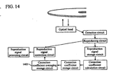
- the apparatus of the present invention may perform plural reproductions on the same track and average the obtained readout signals.
- the apparatus may be configured to calculate correction coefficients from readout signals, respectively, to average the plural correction coefficients by a correction coefficient averaging storage circuit 1401, and to use the average correction coefficient for the readout signal correction in the predetermined area.
- the information reproducing apparatus of the present invention may be configured to detect the frequency of readout signal fluctuation by a readout signal fluctuation frequency detection circuit 1501 and increase or reduce, by a correction coefficient frequency setting circuit 1502, the number of correction coefficients set according to the readout signal fluctuation.
- an optical information recording medium suitable for the information reproducing method of the present invention includes write-protected areas for readout signal fluctuation correction, which are disposed at predetermined intervals in the radial direction of the optical information recording medium.
- the write-protected areas are disposed at the same radius on two or more of the plural information layers.
- Such disposition of the write-protected areas at the same radius has the advantage of being able to reduce the fluctuation components of the readout signal involved in recording.
- information such as an address of a write-protected track is recorded in a disc management area.
- Fig. 15 is a schematic view, in which only four write-protected areas are shown; however, it is to be understood that the number of write-protected areas of the present invention is not limited to this.
- the information reproducing apparatus of the present invention utilizes a disc rotation synchronizing signal obtained from a spindle motor 1901 to store in memory 1903 the correction coefficient in correspondence with a circumferential position on the disc, or equivalently, an angle.
- Angle detection utilizing the disc rotation synchronizing signal is performed by an angle detection circuit 1902, and the readout signal, the correction coefficient, the circumferential position represented by the angle, and so on can be stored in the memory 1903.
- the readout signal correction corresponding to the circumferential position enables providing accurate correction to even the readout signal in a different radial position.
- the optical information reproducing method and the optical information reproducing apparatus of the present invention can suppress the influence of the interlayer crosstalk and thereby achieve accurate reproduction, for example, in the case where the readout signal on the multilayer optical recording medium is affected by the influence of the interlayer crosstalk.
Landscapes
- Engineering & Computer Science (AREA)
- Signal Processing (AREA)
- Physics & Mathematics (AREA)
- Probability & Statistics with Applications (AREA)
- Optical Recording Or Reproduction (AREA)
Applications Claiming Priority (1)
| Application Number | Priority Date | Filing Date | Title |
|---|---|---|---|
| JP2007253034A JP4792443B2 (ja) | 2007-09-28 | 2007-09-28 | 光情報再生方法、光情報再生装置及び光情報記録媒体 |
Publications (3)
| Publication Number | Publication Date |
|---|---|
| EP2043091A2 EP2043091A2 (en) | 2009-04-01 |
| EP2043091A3 EP2043091A3 (en) | 2011-03-23 |
| EP2043091B1 true EP2043091B1 (en) | 2013-07-03 |
Family
ID=39938172
Family Applications (1)
| Application Number | Title | Priority Date | Filing Date |
|---|---|---|---|
| EP08016802.4A Not-in-force EP2043091B1 (en) | 2007-09-28 | 2008-09-24 | Optical information reproducing method and apparatus, and optical information recording medium |
Country Status (4)
| Country | Link |
|---|---|
| US (1) | US20090086602A1 (https=) |
| EP (1) | EP2043091B1 (https=) |
| JP (1) | JP4792443B2 (https=) |
| CN (1) | CN101399069B (https=) |
Families Citing this family (4)
| Publication number | Priority date | Publication date | Assignee | Title |
|---|---|---|---|---|
| RU2511612C2 (ru) * | 2008-12-10 | 2014-04-10 | Панасоник Корпорэйшн | Носитель записи информации, устройство воспроизведения и способ воспроизведения |
| WO2010067556A1 (ja) * | 2008-12-11 | 2010-06-17 | パナソニック株式会社 | 情報記録媒体、再生装置および再生方法 |
| JP5573489B2 (ja) * | 2010-08-23 | 2014-08-20 | ソニー株式会社 | 情報処理装置、および情報処理方法、並びにプログラム |
| JP5417299B2 (ja) * | 2010-11-08 | 2014-02-12 | 日立コンシューマエレクトロニクス株式会社 | 情報再生装置および情報再生方法 |
Family Cites Families (18)
| Publication number | Priority date | Publication date | Assignee | Title |
|---|---|---|---|---|
| US5138594A (en) * | 1990-04-20 | 1992-08-11 | International Business Machines Corporation | Reducing amplitude variations of optical disk readback signals and increasing reliability of track-crossing counts |
| DE69231731T2 (de) * | 1991-06-17 | 2001-06-28 | Sony Corp., Tokio/Tokyo | Plattenaufzeichnungsverfahren |
| JP3266627B2 (ja) | 1991-10-11 | 2002-03-18 | 株式会社日立製作所 | 情報再生装置 |
| JPH1116208A (ja) | 1997-06-19 | 1999-01-22 | Pioneer Electron Corp | 多層情報記録媒体 |
| US6754143B2 (en) * | 2000-03-24 | 2004-06-22 | Matsushita Electric Industrial Co., Ltd. | Optical information recording medium, and method and apparatus for recording/reproducing information thereon |
| JP2002117542A (ja) * | 2000-10-05 | 2002-04-19 | Pioneer Electronic Corp | 多層回転記録媒体及びその記録再生方法並びに記録再生装置 |
| JP2003346348A (ja) * | 2002-05-29 | 2003-12-05 | Nec Corp | 光ディスクおよびその記録再生方法 |
| JP4215497B2 (ja) * | 2002-12-27 | 2009-01-28 | Tdk株式会社 | 光記録媒体 |
| US7859983B2 (en) * | 2003-07-15 | 2010-12-28 | Sharp Kabushiki Kaisha | Optical disk and optical disk recording and reproducing device |
| JP2005038463A (ja) | 2003-07-15 | 2005-02-10 | Sharp Corp | 光ディスクおよび光ディスクの製造方法 |
| JP4138838B2 (ja) * | 2004-05-10 | 2008-08-27 | パイオニア株式会社 | 情報記録媒体、情報記録装置及び方法、並びにコンピュータプログラム |
| JP4349248B2 (ja) * | 2004-10-04 | 2009-10-21 | 株式会社日立製作所 | 光情報記録媒体、その再生方法及びその製造方法 |
| US7948843B2 (en) * | 2004-10-12 | 2011-05-24 | Pioneer Corporation | Information recording medium, apparatus and method for recording information, and computer program |
| JP4370519B2 (ja) | 2004-10-25 | 2009-11-25 | ソニー株式会社 | 光情報再生装置及び光情報再生方法 |
| JP4622454B2 (ja) * | 2004-10-28 | 2011-02-02 | Tdk株式会社 | 多層光記録媒体 |
| JP2007048402A (ja) * | 2005-08-11 | 2007-02-22 | Toshiba Corp | 光ディスク装置 |
| JP4380641B2 (ja) * | 2006-02-14 | 2009-12-09 | 株式会社日立製作所 | 光記録媒体、光記録媒体の評価方法、情報再生方法及び情報記録方法。 |
| JP4614169B2 (ja) | 2006-03-22 | 2011-01-19 | 清水建設株式会社 | 泥水処理設備 |
-
2007
- 2007-09-28 JP JP2007253034A patent/JP4792443B2/ja not_active Expired - Fee Related
-
2008
- 2008-04-15 US US12/102,936 patent/US20090086602A1/en not_active Abandoned
- 2008-09-24 EP EP08016802.4A patent/EP2043091B1/en not_active Not-in-force
- 2008-09-27 CN CN2008101681141A patent/CN101399069B/zh not_active Expired - Fee Related
Also Published As
| Publication number | Publication date |
|---|---|
| EP2043091A2 (en) | 2009-04-01 |
| US20090086602A1 (en) | 2009-04-02 |
| CN101399069B (zh) | 2011-05-11 |
| CN101399069A (zh) | 2009-04-01 |
| EP2043091A3 (en) | 2011-03-23 |
| JP2009087412A (ja) | 2009-04-23 |
| JP4792443B2 (ja) | 2011-10-12 |
Similar Documents
| Publication | Publication Date | Title |
|---|---|---|
| US8164998B2 (en) | Optical disc device | |
| JP4676574B2 (ja) | 情報記録媒体および再生方法 | |
| US20110149704A1 (en) | Signal evaluation method and signal evaluation apparatus | |
| US7782722B2 (en) | Method of adjusting spherical aberration and focus offset and information recording/reproduction apparatus using the same | |
| US7649821B2 (en) | Disk discriminating method and optical disk apparatus | |
| EP2043091B1 (en) | Optical information reproducing method and apparatus, and optical information recording medium | |
| US20080181062A1 (en) | Method and apparatus for controlling focus of an optical information storage medium | |
| EP2026341B1 (en) | Reproducing signal measuring method, signal reproducing apparatus | |
| JP4664425B2 (ja) | 多層光ディスクの記録方法 | |
| JP2005011404A (ja) | 光記録媒体、記録装置及び記録方法 | |
| EP2273497B1 (en) | Multilayered optical disc and its recording method | |
| US7933184B2 (en) | Multilayered optical disc and its recording method | |
| JP2009070510A (ja) | 再生装置、再生方法 | |
| JP4969434B2 (ja) | 光ディスク装置 | |
| US20100177608A1 (en) | Optical disc and method for controlling the same | |
| US7903514B2 (en) | Information reproduction device | |
| RU2321081C2 (ru) | Устройство регулирования фокуса | |
| JP4699142B2 (ja) | 検査用光ディスク、および、光ディスクドライブまたは光ピックアップの検査方法 | |
| JP2003099978A (ja) | 光ディスク装置 | |
| JP2007179656A (ja) | 情報記録再生装置及び記録条件調整方法 | |
| JP2006331463A (ja) | 光ディスク装置 | |
| JP2010152998A (ja) | 多層光ディスクの記録方法、多層光ディスク記録装置、及び多層光ディスク |
Legal Events
| Date | Code | Title | Description |
|---|---|---|---|
| PUAI | Public reference made under article 153(3) epc to a published international application that has entered the european phase |
Free format text: ORIGINAL CODE: 0009012 |
|
| AK | Designated contracting states |
Kind code of ref document: A2 Designated state(s): AT BE BG CH CY CZ DE DK EE ES FI FR GB GR HR HU IE IS IT LI LT LU LV MC MT NL NO PL PT RO SE SI SK TR |
|
| AX | Request for extension of the european patent |
Extension state: AL BA MK RS |
|
| 17P | Request for examination filed |
Effective date: 20100331 |
|
| PUAL | Search report despatched |
Free format text: ORIGINAL CODE: 0009013 |
|
| AK | Designated contracting states |
Kind code of ref document: A3 Designated state(s): AT BE BG CH CY CZ DE DK EE ES FI FR GB GR HR HU IE IS IT LI LT LU LV MC MT NL NO PL PT RO SE SI SK TR |
|
| AX | Request for extension of the european patent |
Extension state: AL BA MK RS |
|
| RIC1 | Information provided on ipc code assigned before grant |
Ipc: G11B 7/24 20060101ALI20110217BHEP Ipc: G11B 7/007 20060101ALI20110217BHEP Ipc: G11B 20/10 20060101ALI20110217BHEP Ipc: G11B 7/005 20060101AFI20081124BHEP |
|
| 17Q | First examination report despatched |
Effective date: 20111005 |
|
| AKX | Designation fees paid |
Designated state(s): AT BE BG CH CY CZ DE DK EE ES FI FR GB GR HR HU IE IS IT LI LT LU LV MC MT NL NO PL PT RO SE SI SK TR |
|
| GRAP | Despatch of communication of intention to grant a patent |
Free format text: ORIGINAL CODE: EPIDOSNIGR1 |
|
| GRAJ | Information related to disapproval of communication of intention to grant by the applicant or resumption of examination proceedings by the epo deleted |
Free format text: ORIGINAL CODE: EPIDOSDIGR1 |
|
| GRAP | Despatch of communication of intention to grant a patent |
Free format text: ORIGINAL CODE: EPIDOSNIGR1 |
|
| GRAP | Despatch of communication of intention to grant a patent |
Free format text: ORIGINAL CODE: EPIDOSNIGR1 |
|
| INTG | Intention to grant announced |
Effective date: 20130417 |
|
| RIN1 | Information on inventor provided before grant (corrected) |
Inventor name: MIYAMOTO, HARUKAZU Inventor name: MINEMURA, HIROYUKI Inventor name: KIKUGAWA, ATSUSHI Inventor name: USHIYAMA, JUNKO Inventor name: KUROKAWA, TAKAHIRO |
|
| GRAS | Grant fee paid |
Free format text: ORIGINAL CODE: EPIDOSNIGR3 |
|
| GRAA | (expected) grant |
Free format text: ORIGINAL CODE: 0009210 |
|
| AK | Designated contracting states |
Kind code of ref document: B1 Designated state(s): AT BE BG CH CY CZ DE DK EE ES FI FR GB GR HR HU IE IS IT LI LT LU LV MC MT NL NO PL PT RO SE SI SK TR |
|
| REG | Reference to a national code |
Ref country code: GB Ref legal event code: FG4D |
|
| REG | Reference to a national code |
Ref country code: CH Ref legal event code: EP Ref country code: AT Ref legal event code: REF Ref document number: 620166 Country of ref document: AT Kind code of ref document: T Effective date: 20130715 |
|
| REG | Reference to a national code |
Ref country code: IE Ref legal event code: FG4D |
|
| REG | Reference to a national code |
Ref country code: DE Ref legal event code: R096 Ref document number: 602008025664 Country of ref document: DE Effective date: 20130829 |
|
| PG25 | Lapsed in a contracting state [announced via postgrant information from national office to epo] |
Ref country code: SI Free format text: LAPSE BECAUSE OF FAILURE TO SUBMIT A TRANSLATION OF THE DESCRIPTION OR TO PAY THE FEE WITHIN THE PRESCRIBED TIME-LIMIT Effective date: 20130703 |
|
| REG | Reference to a national code |
Ref country code: AT Ref legal event code: MK05 Ref document number: 620166 Country of ref document: AT Kind code of ref document: T Effective date: 20130703 |
|
| REG | Reference to a national code |
Ref country code: NL Ref legal event code: VDEP Effective date: 20130703 |
|
| REG | Reference to a national code |
Ref country code: LT Ref legal event code: MG4D |
|
| PG25 | Lapsed in a contracting state [announced via postgrant information from national office to epo] |
Ref country code: PT Free format text: LAPSE BECAUSE OF FAILURE TO SUBMIT A TRANSLATION OF THE DESCRIPTION OR TO PAY THE FEE WITHIN THE PRESCRIBED TIME-LIMIT Effective date: 20131104 Ref country code: IS Free format text: LAPSE BECAUSE OF FAILURE TO SUBMIT A TRANSLATION OF THE DESCRIPTION OR TO PAY THE FEE WITHIN THE PRESCRIBED TIME-LIMIT Effective date: 20131103 Ref country code: NO Free format text: LAPSE BECAUSE OF FAILURE TO SUBMIT A TRANSLATION OF THE DESCRIPTION OR TO PAY THE FEE WITHIN THE PRESCRIBED TIME-LIMIT Effective date: 20131003 Ref country code: AT Free format text: LAPSE BECAUSE OF FAILURE TO SUBMIT A TRANSLATION OF THE DESCRIPTION OR TO PAY THE FEE WITHIN THE PRESCRIBED TIME-LIMIT Effective date: 20130703 Ref country code: SE Free format text: LAPSE BECAUSE OF FAILURE TO SUBMIT A TRANSLATION OF THE DESCRIPTION OR TO PAY THE FEE WITHIN THE PRESCRIBED TIME-LIMIT Effective date: 20130703 Ref country code: HR Free format text: LAPSE BECAUSE OF FAILURE TO SUBMIT A TRANSLATION OF THE DESCRIPTION OR TO PAY THE FEE WITHIN THE PRESCRIBED TIME-LIMIT Effective date: 20130703 Ref country code: LT Free format text: LAPSE BECAUSE OF FAILURE TO SUBMIT A TRANSLATION OF THE DESCRIPTION OR TO PAY THE FEE WITHIN THE PRESCRIBED TIME-LIMIT Effective date: 20130703 Ref country code: CY Free format text: LAPSE BECAUSE OF FAILURE TO SUBMIT A TRANSLATION OF THE DESCRIPTION OR TO PAY THE FEE WITHIN THE PRESCRIBED TIME-LIMIT Effective date: 20130731 Ref country code: BE Free format text: LAPSE BECAUSE OF FAILURE TO SUBMIT A TRANSLATION OF THE DESCRIPTION OR TO PAY THE FEE WITHIN THE PRESCRIBED TIME-LIMIT Effective date: 20130703 |
|
| PG25 | Lapsed in a contracting state [announced via postgrant information from national office to epo] |
Ref country code: ES Free format text: LAPSE BECAUSE OF FAILURE TO SUBMIT A TRANSLATION OF THE DESCRIPTION OR TO PAY THE FEE WITHIN THE PRESCRIBED TIME-LIMIT Effective date: 20131014 Ref country code: FI Free format text: LAPSE BECAUSE OF FAILURE TO SUBMIT A TRANSLATION OF THE DESCRIPTION OR TO PAY THE FEE WITHIN THE PRESCRIBED TIME-LIMIT Effective date: 20130703 Ref country code: GR Free format text: LAPSE BECAUSE OF FAILURE TO SUBMIT A TRANSLATION OF THE DESCRIPTION OR TO PAY THE FEE WITHIN THE PRESCRIBED TIME-LIMIT Effective date: 20131004 Ref country code: LV Free format text: LAPSE BECAUSE OF FAILURE TO SUBMIT A TRANSLATION OF THE DESCRIPTION OR TO PAY THE FEE WITHIN THE PRESCRIBED TIME-LIMIT Effective date: 20130703 Ref country code: NL Free format text: LAPSE BECAUSE OF FAILURE TO SUBMIT A TRANSLATION OF THE DESCRIPTION OR TO PAY THE FEE WITHIN THE PRESCRIBED TIME-LIMIT Effective date: 20130703 Ref country code: PL Free format text: LAPSE BECAUSE OF FAILURE TO SUBMIT A TRANSLATION OF THE DESCRIPTION OR TO PAY THE FEE WITHIN THE PRESCRIBED TIME-LIMIT Effective date: 20130703 |
|
| RAP2 | Party data changed (patent owner data changed or rights of a patent transferred) |
Owner name: HITACHI CONSUMER ELECTRONICS CO., LTD. |
|
| PG25 | Lapsed in a contracting state [announced via postgrant information from national office to epo] |
Ref country code: CY Free format text: LAPSE BECAUSE OF FAILURE TO SUBMIT A TRANSLATION OF THE DESCRIPTION OR TO PAY THE FEE WITHIN THE PRESCRIBED TIME-LIMIT Effective date: 20130703 |
|
| REG | Reference to a national code |
Ref country code: DE Ref legal event code: R082 Ref document number: 602008025664 Country of ref document: DE Representative=s name: PATENTANWAELTE STREHL, SCHUEBEL-HOPF & PARTNER, DE Effective date: 20140306 Ref country code: DE Ref legal event code: R081 Ref document number: 602008025664 Country of ref document: DE Owner name: HITACHI CONSUMER ELECTRONICS CO., LTD., JP Free format text: FORMER OWNER: HITACHI, LTD., TOKYO, JP Effective date: 20140306 Ref country code: DE Ref legal event code: R082 Ref document number: 602008025664 Country of ref document: DE Representative=s name: STREHL SCHUEBEL-HOPF & PARTNER MBB PATENTANWAE, DE Effective date: 20140306 |
|
| PG25 | Lapsed in a contracting state [announced via postgrant information from national office to epo] |
Ref country code: CZ Free format text: LAPSE BECAUSE OF FAILURE TO SUBMIT A TRANSLATION OF THE DESCRIPTION OR TO PAY THE FEE WITHIN THE PRESCRIBED TIME-LIMIT Effective date: 20130703 Ref country code: RO Free format text: LAPSE BECAUSE OF FAILURE TO SUBMIT A TRANSLATION OF THE DESCRIPTION OR TO PAY THE FEE WITHIN THE PRESCRIBED TIME-LIMIT Effective date: 20130703 Ref country code: DK Free format text: LAPSE BECAUSE OF FAILURE TO SUBMIT A TRANSLATION OF THE DESCRIPTION OR TO PAY THE FEE WITHIN THE PRESCRIBED TIME-LIMIT Effective date: 20130703 Ref country code: SK Free format text: LAPSE BECAUSE OF FAILURE TO SUBMIT A TRANSLATION OF THE DESCRIPTION OR TO PAY THE FEE WITHIN THE PRESCRIBED TIME-LIMIT Effective date: 20130703 Ref country code: EE Free format text: LAPSE BECAUSE OF FAILURE TO SUBMIT A TRANSLATION OF THE DESCRIPTION OR TO PAY THE FEE WITHIN THE PRESCRIBED TIME-LIMIT Effective date: 20130703 Ref country code: MC Free format text: LAPSE BECAUSE OF FAILURE TO SUBMIT A TRANSLATION OF THE DESCRIPTION OR TO PAY THE FEE WITHIN THE PRESCRIBED TIME-LIMIT Effective date: 20130703 |
|
| REG | Reference to a national code |
Ref country code: CH Ref legal event code: PL |
|
| PLBE | No opposition filed within time limit |
Free format text: ORIGINAL CODE: 0009261 |
|
| STAA | Information on the status of an ep patent application or granted ep patent |
Free format text: STATUS: NO OPPOSITION FILED WITHIN TIME LIMIT |
|
| PG25 | Lapsed in a contracting state [announced via postgrant information from national office to epo] |
Ref country code: IT Free format text: LAPSE BECAUSE OF FAILURE TO SUBMIT A TRANSLATION OF THE DESCRIPTION OR TO PAY THE FEE WITHIN THE PRESCRIBED TIME-LIMIT Effective date: 20130703 |
|
| 26N | No opposition filed |
Effective date: 20140404 |
|
| REG | Reference to a national code |
Ref country code: IE Ref legal event code: MM4A |
|
| REG | Reference to a national code |
Ref country code: DE Ref legal event code: R097 Ref document number: 602008025664 Country of ref document: DE Effective date: 20140404 |
|
| PG25 | Lapsed in a contracting state [announced via postgrant information from national office to epo] |
Ref country code: LI Free format text: LAPSE BECAUSE OF NON-PAYMENT OF DUE FEES Effective date: 20130930 Ref country code: CH Free format text: LAPSE BECAUSE OF NON-PAYMENT OF DUE FEES Effective date: 20130930 Ref country code: IE Free format text: LAPSE BECAUSE OF NON-PAYMENT OF DUE FEES Effective date: 20130924 |
|
| PG25 | Lapsed in a contracting state [announced via postgrant information from national office to epo] |
Ref country code: MT Free format text: LAPSE BECAUSE OF FAILURE TO SUBMIT A TRANSLATION OF THE DESCRIPTION OR TO PAY THE FEE WITHIN THE PRESCRIBED TIME-LIMIT Effective date: 20130703 Ref country code: TR Free format text: LAPSE BECAUSE OF FAILURE TO SUBMIT A TRANSLATION OF THE DESCRIPTION OR TO PAY THE FEE WITHIN THE PRESCRIBED TIME-LIMIT Effective date: 20130703 |
|
| PG25 | Lapsed in a contracting state [announced via postgrant information from national office to epo] |
Ref country code: HU Free format text: LAPSE BECAUSE OF FAILURE TO SUBMIT A TRANSLATION OF THE DESCRIPTION OR TO PAY THE FEE WITHIN THE PRESCRIBED TIME-LIMIT; INVALID AB INITIO Effective date: 20080924 Ref country code: LU Free format text: LAPSE BECAUSE OF NON-PAYMENT OF DUE FEES Effective date: 20130924 Ref country code: BG Free format text: LAPSE BECAUSE OF FAILURE TO SUBMIT A TRANSLATION OF THE DESCRIPTION OR TO PAY THE FEE WITHIN THE PRESCRIBED TIME-LIMIT Effective date: 20130703 |
|
| REG | Reference to a national code |
Ref country code: FR Ref legal event code: PLFP Year of fee payment: 8 |
|
| PGFP | Annual fee paid to national office [announced via postgrant information from national office to epo] |
Ref country code: DE Payment date: 20150916 Year of fee payment: 8 Ref country code: GB Payment date: 20150923 Year of fee payment: 8 |
|
| PGFP | Annual fee paid to national office [announced via postgrant information from national office to epo] |
Ref country code: FR Payment date: 20150811 Year of fee payment: 8 |
|
| REG | Reference to a national code |
Ref country code: DE Ref legal event code: R119 Ref document number: 602008025664 Country of ref document: DE |
|
| GBPC | Gb: european patent ceased through non-payment of renewal fee |
Effective date: 20160924 |
|
| REG | Reference to a national code |
Ref country code: FR Ref legal event code: ST Effective date: 20170531 |
|
| PG25 | Lapsed in a contracting state [announced via postgrant information from national office to epo] |
Ref country code: GB Free format text: LAPSE BECAUSE OF NON-PAYMENT OF DUE FEES Effective date: 20160924 Ref country code: FR Free format text: LAPSE BECAUSE OF NON-PAYMENT OF DUE FEES Effective date: 20160930 Ref country code: DE Free format text: LAPSE BECAUSE OF NON-PAYMENT OF DUE FEES Effective date: 20170401 |