EP2042880A2 - Verfahren und Vorrichtung zur Diagnose von Umrichterverknüpfungen - Google Patents
Verfahren und Vorrichtung zur Diagnose von Umrichterverknüpfungen Download PDFInfo
- Publication number
- EP2042880A2 EP2042880A2 EP08165348A EP08165348A EP2042880A2 EP 2042880 A2 EP2042880 A2 EP 2042880A2 EP 08165348 A EP08165348 A EP 08165348A EP 08165348 A EP08165348 A EP 08165348A EP 2042880 A2 EP2042880 A2 EP 2042880A2
- Authority
- EP
- European Patent Office
- Prior art keywords
- inverter
- signal
- switching device
- controller
- sensor
- Prior art date
- Legal status (The legal status is an assumption and is not a legal conclusion. Google has not performed a legal analysis and makes no representation as to the accuracy of the status listed.)
- Withdrawn
Links
- 238000000034 method Methods 0.000 title claims abstract description 56
- 230000008878 coupling Effects 0.000 claims description 32
- 238000010168 coupling process Methods 0.000 claims description 32
- 238000005859 coupling reaction Methods 0.000 claims description 32
- 230000003466 anti-cipated effect Effects 0.000 claims description 9
- 238000002405 diagnostic procedure Methods 0.000 claims description 6
- 230000008439 repair process Effects 0.000 abstract description 5
- 238000003745 diagnosis Methods 0.000 abstract 1
- 239000000523 sample Substances 0.000 description 9
- 238000012360 testing method Methods 0.000 description 8
- 238000006243 chemical reaction Methods 0.000 description 4
- 238000011161 development Methods 0.000 description 3
- 238000004519 manufacturing process Methods 0.000 description 3
- 230000005355 Hall effect Effects 0.000 description 2
- 230000008901 benefit Effects 0.000 description 2
- 238000013461 design Methods 0.000 description 2
- 238000012544 monitoring process Methods 0.000 description 2
- 230000004044 response Effects 0.000 description 2
- 230000003213 activating effect Effects 0.000 description 1
- 230000003750 conditioning effect Effects 0.000 description 1
- 230000001066 destructive effect Effects 0.000 description 1
- 238000010586 diagram Methods 0.000 description 1
- 238000012986 modification Methods 0.000 description 1
- 230000004048 modification Effects 0.000 description 1
- 238000011160 research Methods 0.000 description 1
Images


Classifications
-
- G—PHYSICS
- G01—MEASURING; TESTING
- G01R—MEASURING ELECTRIC VARIABLES; MEASURING MAGNETIC VARIABLES
- G01R31/00—Arrangements for testing electric properties; Arrangements for locating electric faults; Arrangements for electrical testing characterised by what is being tested not provided for elsewhere
- G01R31/40—Testing power supplies
- G01R31/42—AC power supplies
-
- G—PHYSICS
- G01—MEASURING; TESTING
- G01R—MEASURING ELECTRIC VARIABLES; MEASURING MAGNETIC VARIABLES
- G01R31/00—Arrangements for testing electric properties; Arrangements for locating electric faults; Arrangements for electrical testing characterised by what is being tested not provided for elsewhere
- G01R31/28—Testing of electronic circuits, e.g. by signal tracer
- G01R31/2832—Specific tests of electronic circuits not provided for elsewhere
- G01R31/2836—Fault-finding or characterising
Definitions
- the present invention relates to inverters with a controller connected to switching devices that are between a DC input and a multi-phase output and more specifically to an apparatus and method for diagnosing inverter linkages.
- Power plants are linked to power consuming facilities (e.g., buildings, factories, etc.) via utility grids designed so as to be extremely efficient in delivering large amounts of power.
- power is delivered over long distances as low frequency three-phase AC current.
- low frequency AC current is sometimes not suitable for end use in consuming facilities.
- power delivered by a utility has to be converted to a usable form.
- a typical power "conditioning" configuration includes an AC-to-DC rectifier that converts the utility AC power to DC across positive and negative DC buses (i.e., across a DC link) and an inverter linked to the DC link that converts the DC power back to three-phase AC power having an end-useable form (e.g., three-phase relatively high frequency AC voltage).
- a controller controls the inverter in a manner calculated to provide voltage waveforms required by the consuming facility.
- an inverter includes a plurality of switches that can be controlled to link and delink the positive and negative DC buses to motor supply lines. The linking/delinking sequence causes voltage pulses on the motor supply lines that together define alternating voltage waveforms.
- a typical three phase inverter structure includes six switching devices (e.g., IGBTs) that are arranged between positive and negative DC buses of a rectifier apparatus to form first, second and third switch legs where each leg includes a pair of switches.
- the first leg includes first and second switches arranged in series
- the second leg includes third and fourth switches in series
- the third leg includes fifth and sixth switches where nodes between each switch pair are linked to different phases of a three phase load.
- the above topology is generally referred to as a single inverter structure.
- testing the inverter with a low voltage supply does not test the ability of the switching devices to handle the commutations at higher voltages and currents.
- the method identifies that there is a problem with the inverter but does not pinpoint the source of the problem because it is often too difficult to diagnose the inverter during high frequency operation.
- At least some inventive embodiments provide a method for diagnosing inverter linkages during a diagnostic procedure prior to normal inverter control.
- the method can be used with inverters having an inverter controller and a set of inverter switching devices, the inverter switching devices including at least first and second switching devices and inverter output lines, each switching device including a gate terminal, the controller linked to each gate terminal to control each switching device independently.
- the method comprising the steps of providing a display device for displaying at least one signal waveform, coupling one of a voltage sensor to the gate terminal of the first switching device and a current sensor to the inverter output line associated with the first switching device, the sensor generating a sensor signal, using the inverter controller to provide a first gate turn on signal to the first switching device and presenting the sensor signal via the display device for observation by a user.
- the method can further include the step of using the inverter controller to provide a second gate turn on signal to the second switching device where the first and second turn on signals are provided to the first and second switching devices simultaneously.
- the inverter can include at least first and second poles, each pole including a pair of switching devices linked in series between positive and negative DC buses, the switches in each pair linked at a common node to one of the inverter output lines, the first and second poles including the first and second switching devices, the first switching device linked to one of a positive DC bus and a negative DC bus and the second switching device linked to the other of the positive and the negative DC buses.
- the step of coupling one of a voltage sensor and a current sensor can include coupling a first current sensor to a first inverter output line associated with the first inverter switching device so that the first current sensor generates a first sensor current signal.
- the method can further include the steps of coupling a second current sensor to a second inverter output line so that the second current sensor generates a second sensor current signal and presenting the second sensor current signal via the display device for observation by a user, the first and second sensor current signals presented simultaneously. Additionally, the method can include the step of comparing the presented sensor current signals to anticipated current signals.
- the step of using the inverter controller to provide the first gate turn on signal can include using the controller to provide a first sequence of gate turn on signals to the first switching device.
- the step of using the inverter controller to provide the second gate turn on signal can include using the controller to provide a second sequence of gate turn on signals to the second switching device.
- Each of the first and second sequences can include at least two turn on signals.
- the step of coupling one of a voltage sensor and a current sensor can include coupling a voltage sensor to the gate terminal of the first switching device.
- the step of using the inverter controller to provide a first gate turn on signal to the first switching device can include using the controller to provide a first gate turn on signal having a predetermined pulse width.
- the step of using the inverter controller to provide a first gate turn on signal to the first switching device can further include using the controller to provide a second gate turn on signal to the first switching device that has a predetermined pulse width and that is separated from the first gate turn on signal by a predetermined interval.
- the step of using the inverter controller to provide a first gate turn on signal to the first switching device can further include using the controller to provide a separate gate turn on signal to each of the inverter switching devices in a consecutive sequence.
- inventions include a method for use with an inverter and an inverter controller during a diagnostic procedure prior to normal inverter control.
- the inverter can include a set of inverter switching devices including at least first, second, third and fourth switching devices and inverter output lines, each switching device including a gate terminal, the controller linked to each gate terminal to control each switching device independently.
- the method can comprise the steps of providing a display device for displaying at least one signal waveform, coupling a voltage sensor to the inverter at a location electrically linked to the gate terminal of a first switching device, the sensor generating a voltage sensor signal, using the inverter controller to provide a first gate turn on signal to the first switching device, and presenting the voltage sensor signal via the display device for observation by a user.
- the inverter can include at least first and second poles, the first pole including the first and second switching devices linked in series between a positive DC bus and a negative DC bus and linked at a common coupling point to a first of the inverter output lines and the second pole including the third and fourth switching devices linked in series between the positive and negative DC buses and linked at a common coupling point to a second of the inverter output lines, the first and third switching devices linked to the positive DC bus.
- the method can further include using the inverter controller to provide a consecutive sequence of gate turn on signals to the first through fourth switching devices.
- the inverter can further include a third pole including fifth and sixth switching devices linked in series between the positive and negative DC buses and linked at a common coupling point to a third of the inverter output lines, the fifth switching device linked to the positive DC bus.
- the step of using the inverter controller to provide a consecutive sequence of gate turn on signals can include using the inverter controller to provide a consecutive sequence of gate turn on signals to the first through sixth switching devices.
- the method can include repeating the steps of using the inverter controller to provide a first gate turn on signal to the first switching device; and presenting the voltage sensor signal via the display device for observation by a user for each of the inverter switching devices where, the voltage sensor is coupled to a gate terminal of a different one of the switching devices each time.
- the inverter can include at least first and second poles where each pole includes a pair of switching devices linked in series between a positive DC rail and a negative DC rail, the first pole switches linked at a first common coupling point to a first inverter output line and including a first switching device linked to the positive DC bus, the second pole switches linked at a second common coupling point to a second inverter output line and including a second switching device linked to the negative DC bus, each switching device including a gate terminal, the controller linked to each gate terminal to control each switching device independently.
- the method can include the steps providing a display device for displaying at least one signal waveform, coupling a first current sensor to at least one of the first and second inverter output lines, the sensor generating a first sensor current signal, using the inverter controller to simultaneously provide a first gate turn on signal to the first switching device and a second gate turn on signal to the second switching device, and presenting the first sensor current signal via the display device for observation by a user.
- the step of coupling can include coupling the first current sensor to the first inverter output line, the method further including the step of coupling a second current sensor to the second inverter output line to generate a second sensor current signal and wherein the step of presenting includes simultaneously presenting each of the first and second sensor current signals via the display device.
- the first current sensor can be a feedback sensor.
- the method may further include the of identifying whether the first sensor current signal an unanticipated current signal.
- the step of using the inverter controller to simultaneously provide a first gate turn on signal to the first switching device and a second gate turn on signal to the second switching device further can further comprise causing the inverter controller to simultaneously provide a third gate turn on signal to the first switching device and a fourth gate turn on signal to the second switching device.
- the step of using the inverter controller to simultaneously provide a first gate turn on signal to the first switching device and a second gate turn on signal to the second switching device can further include selecting a selected pulse width.
- the first gate turn on signal can have a first pulse width equal to the selected pulse width and the second gate turn on signal can have a second pulse width equal to the selected pulse width.
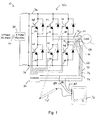
- Fig. 1 is a schematic diagram of an exemplary power conversion assembly including an inverter that can be diagnosed according to the present invention
- Fig. 2 is a flow chart illustrating a method of diagnosing an inverter according to a first inventive embodiment
- Fig. 3 is a flow chart illustrating a method of diagnosing an inverter according to a second inventive embodiment.
- system 10 receives power from three AC supply lines collectively identified by numeral 20 and provides three phase AC power to a load 22 (e.g., a motor or a choke) via first, second and third AC output lines 24, 26 and 28, respectively.
- system 10 includes a rectifier 30 and an inverter 32.
- Rectifier 30 receives three phase AC input voltages on supply lines 20 and converts those AC voltages to a DC potential across positive and negative DC rails or buses 34 and 36, respectively.
- System 10 can be configured as a high-horsepower motor drive, which means that the DC buses 34 and 36 can carry high voltages and inverter 32 can provide large currents.
- inverter 14 includes six switching devices 38, 40, 42, 44, 46 and 48 arranged in three device pairs.
- Each switching device includes an IGBT connected in parallel with a flyback diode.
- the switching devices in each pair are linked at a central node where each central node is provided as an inverter output.
- Switches 38 and 40 form a first pair and are connected to output line 24.
- Switches 42 and 44 form a second pair and are connected to output line 26.
- Switches 46 and 48 form a third pair and are connected to output line 28.
- Each pair of switches extends between positive and negative DC rails 34 and 36.
- Switches 38, 42, and 46 are connected to positive DC bus 34, and switches 40, 44 and 48 are connected to negative DC bus 36.
- system 10 also includes a PWM controller 50 that is linked to inverter 32 for providing control signals to the subsets of switches that comprise the inverter 32.
- Controller 50 includes control lines 52, 54, 56, 58, 60, and 62 that are each connected to the gate of one of the switching devices 38, 40, 42, 44, 46 and 48, respectively.
- inverter 32 includes current feedback sensors 64, 66, and 68 that are connected to output lines 24, 26, and 28, respectively.
- Current sensors 64, 66, and 68 are connected to controller 50 on feedback lines 70, 72 and 74, respectively.
- Current sensors 64, 66, and 68 can be Hall effect sensors and the like.
- controller 50 provides gate signals on control lines 52, 54, 56, 58, 60, and 62 to switching devices 38, 40, 42, 44, 46, and 48 to convert the DC voltage across DC bus 34 and 36 to three phase AC voltage that is delivered to load 22 on output lines 24, 26, and 28.
- a display device 76 can be used to view information about system 10 to diagnose inverter 32.
- Display device 76 includes display inputs 78, 80, 72, and 84.
- Display device 76 may be an oscilloscope and the like.
- Display inputs may be passive probes, differential voltage probes, current probes and the like.
- display inputs 78, 80, 72, and 84 can be used to probe various test points in system 10 in order to present information about system 10 on display device 76.
- Display input 78 may be used to probe control lines 52, 54, 56, 58, 60, and 62 to verify that the correct signals are being provided to switching devices 38, 40, 42, 44, 46 and 48. Additional display inputs may be used to simultaneously probe more than one of control lines 52, 54, 56, 58, 60, and 62.
- Display inputs 80, 82, and 84 may be used to monitor the current of the signals on output lines 24, 26 and 28.
- display inputs 80, 82, and 84 may be connected to feedback lines 70, 72 and 74 to monitor the voltage of the signals provided by the current sensors 64, 66, and 68 to controller 50.
- display inputs 80, 82 and 84 may be current probes that monitor output lines 24, 26, and 28.
- inverter 32 If inverter 32 is both configured and operating correctly, controller 50 does not turn on both switching devices in a switching pair at the same time and, hence, no damaging current surges are created. If the inverter linkages are connected improperly (e.g., the gate signals are connected improperly) so that both switching devices in a switching pair are turned on at the same time, a short circuit will occur between the high voltage DC buses 34 and 36, which produces a large current surge that can irreparably damage power conversion system 32. Hence, inverter 32 should be diagnosed to determine whether inverter 32 is operating correctly before commencing normal inverter operation. For example, inverter 32 can be diagnosed at a production facility, upon commissioning, or after a repair procedure.
- Fig. 2 illustrates a method of diagnosing an inverter, such as inverter 32 of Fig. 1 , and an inverter controller, such controller 50, prior to normal inverter operation.
- a diagnostics program is provided to controller 50 at step102.
- the diagnostics program may be saved into memory on controller 50 to be selected by a user from a plurality of selectable controller programs or flashed into memory on controller 50.
- the diagnostics program is configured to cause controller 50 to provide gate control signals on control lines 52, 54, 56, 58, 60, and 62 as is discussed below.
- step 104 display input 78 is linked to one of control lines 52, 54, 56, 58, 60, and 62 at a test point nearest the associated switching device 38, 40, 42, 44, 46 or 48 to determine whether controller 50 is providing the correct gate control signal to the linked control line.
- the diagnostics program is run by controller 50 to provide a gate control signal to the control line to which display input 78 is linked.
- the gate control signal may be a single pulse or a plurality of pulses.
- the diagnostics program is configured to control controller 50 in response to user commands that are inputted through a human interface module connected to controller 50. Controller 50 can also be connected to a computer or other like device capable of controlling system 10.
- the diagnostics program is configured to allow a user to set a number of parameters for the gate control signal.
- the parameters that can be set are the selection of the switching device that is to be provided with a gate control signal, the number of pulses comprising the gate control signal, and the pulse width. The duration between pulses may also be a selectable parameter.
- the user presses a start button on the human interface module that triggers controller 50 to provide a gate control signal as specified by the parameters (e.g., controller 50 provides a single 35 microsecond pulse to switching device 38; controller 50 provides two 70 microsecond pulses to switching device 48).
- the switching device selected by the user is the switching device connected to the control line to which display input 78 is linked.
- the provided gate control signal is analyzed by monitoring display device 76 to determine whether the gate control signal is being provided to the anticipated switching device.
- the anticipated switching device is the switching device associated with the control line that was linked to display input 78 during step 104. If the gate control signal is being provided to the anticipated switching device, display device 76 will show the presence of the gate control signal on the control line that is linked to display input 78. If no signal is detected by display input 78 when linked to the control line of the anticipated switching device or an unanticipated signal is detected on a control line that should not be receiving a gate control signal at that time, the unanticipated signal can be identified at step 110.
- each of the other control lines may be probed while resending the gate control signal provided at step 106 to determine whether the provided gate control signal is being received by at least one unanticipated switching device.
- all six control lines can be simultaneously monitored on display device 76, or by additional display devices, while gate control signals are provided sequentially to each control line.
- steps 104, 106, 108, and 110 may be repeated for each of the other switching devices until it has been verified that the gate control signals are being provided to the correct switching device or a fault condition with controller 50 or control lines 52, 54, 56, 58, 60, and 62 has been found.
- inverter 32 or controller 50 may then be repaired and the method of Fig. 2 may be repeated to verify the repair.
- the diagnostics program may be configured to automatically control controller 50 to sequentially provide gate control signals to the switching devices on the six control lines.
- the diagnostics program may be configured to automatically provide the gate control signals or wait for a user prompt between each successive gate control signal to allow the user to link display input 78 to the next control line in the sequence.
- additional display inputs 78 may probe test points on control lines 52, 54, 56, 58, 60, and 62 to simultaneously monitor the signals on control lines 52, 54, 56, 58, 60, and 62.
- the diagnostics program can control controller 50 to sequentially provide gate control signals on each of control lines 52, 54, 56, 58, 60, and 62 in a predetermined sequence. All six control lines may then be simultaneously monitored on display device 76, or by additional display devices, to analyze the provided gate control signals and identify any unanticipated signals.
- Fig. 3 illustrates a method of diagnosing an inverter and an inverter controller according to a further embodiment.
- the method of Fig. 3 is helpful when more information about the operation of system 20 is required, it is not possible to probe the control lines at test points near the switching devices, or there may be a fault condition between the test points and the switching devices.
- Fig. 3 illustrates a method of diagnosing an inverter, such as inverter 32 of Fig. 1 , and an inverter controller, such controller 50, prior to normal inverter operation. Following the start at step 120, a diagnostics program is provided to controller 50 at step122.
- the diagnostics program may be saved into memory on controller 50 to be selected by a user from a plurality of selectable controller programs or flashed into memory on controller 50.
- the diagnostics program is configured to cause controller 50 to provide gate control signals on control lines 52, 54, 56, 58, 60, and 62 as is discussed below.
- display inputs 80, 82, and 84 are linked to feedback lines 70, 72, and 74, respectively, to monitor the signals provided by the current sensors 64, 66, and 68 that sense the current on output lines 24, 26, and 28.
- display inputs 80, 82, and 84 may be Hall effect sensors that directly monitor the current on output lines 24, 26, and 28.
- the voltages are output lines 24, 26, and 28 may also be monitored.
- the diagnostics program is run by controller 50 to provide gate control signals to the control line to which display input 78 is linked.
- the diagnostics program is configured to control controller 50 in response to user commands that are inputted through the human interface module connected to controller 50. Controller 50 can also be connected to a computer or other like device capable of controlling system 10.
- the diagnostics program is configured to allow a user to set a number of parameters for the gate control signals. The parameters that can be set are the selection of the two switching devices that are to be provided with a gate control signals, the number of pulses comprising each of the gate control signals, and the pulse width.
- the two switching devices are switched on in order to produce one of six possible current states produced when two switches from different poles and connected to different voltage inputs are switched on simultaneously (i.e., I out of U and into V, I out of U and into W, I out of V and into U, I out of V and into W, I out of W and into U, and I out of W and into V). These current states are produced by six corresponding switch combinations. Providing two pulses allows the user to evaluate the ability of the switching devices to robustly handle commutations when supplied with high operational voltages. The duration between pulses may also be a selectable parameter.
- controller 50 provides a single 35 microsecond pulse to switching device 38 while simultaneously providing a single 35 microsecond pulse to switching device 44; controller 50 provides two 35 microsecond pulses to switching device 40 while simultaneously providing two single 35 microsecond pulses to switching device 46).
- Controller 50 may be programmed to restrict the diagnosis program from turning on both switches in a switch pair and from providing more than two pulses per gate control signal. Limiting the pulse width and limited number of pulses ensures that even if two switches in a switch pair are turned on, the possibility of a catastrophic short circuit is minimized.
- the output currents resulting from the provided gate control signals are analyzed by monitoring display device 76 to observe whether the two anticipated switching devices are being switched on, the switching devices are operating correctly, the feedback sensors are operating correctly, and the entire system 10 is operating correctly.
- the anticipated switching devices are the two switching devices selected by the user in step 126.
- unanticipated signals are identified and can provide information about why inverter 32 or controller 50 is not operating correctly.
- steps 126, 128, and 130 may be repeated for each of the other remaining combinations of switching devices to observe all six of the corresponding current states. When a fault condition is indicated by the identification of unanticipated signals, inverter 32 or controller 50 may then be repaired and the method of Fig. 3 may be repeated to verify the repair.
- diagnosis program could be configured to cause controller 50 to provide anticipated waveforms on display device 76 that correspond to the signals that should be produced for comparison by the user.
- methods of Figs. 2 and 3 can be adapted to be used with a multiple inverter system in order to evaluate pulse delay between master and slave.
Landscapes
- Engineering & Computer Science (AREA)
- Physics & Mathematics (AREA)
- General Physics & Mathematics (AREA)
- Power Engineering (AREA)
- General Engineering & Computer Science (AREA)
- Inverter Devices (AREA)
Applications Claiming Priority (1)
| Application Number | Priority Date | Filing Date | Title |
|---|---|---|---|
| US11/864,179 US20090085572A1 (en) | 2007-09-28 | 2007-09-28 | Method and apparatus for diagnosing inverter linkages |
Publications (1)
| Publication Number | Publication Date |
|---|---|
| EP2042880A2 true EP2042880A2 (de) | 2009-04-01 |
Family
ID=40219449
Family Applications (1)
| Application Number | Title | Priority Date | Filing Date |
|---|---|---|---|
| EP08165348A Withdrawn EP2042880A2 (de) | 2007-09-28 | 2008-09-29 | Verfahren und Vorrichtung zur Diagnose von Umrichterverknüpfungen |
Country Status (2)
| Country | Link |
|---|---|
| US (1) | US20090085572A1 (de) |
| EP (1) | EP2042880A2 (de) |
Cited By (2)
| Publication number | Priority date | Publication date | Assignee | Title |
|---|---|---|---|---|
| CN101963655A (zh) * | 2009-07-21 | 2011-02-02 | 通用汽车环球科技运作公司 | 用于检测逆变器子模块的异常工作的方法、系统和装置 |
| CN102455769A (zh) * | 2010-10-20 | 2012-05-16 | 鸿富锦精密工业(深圳)有限公司 | 电源装置 |
Families Citing this family (4)
| Publication number | Priority date | Publication date | Assignee | Title |
|---|---|---|---|---|
| WO2011034253A1 (ko) * | 2009-09-15 | 2011-03-24 | 한국전기안전공사 | 원격 전기 안전 진단 시스템 및 장치 |
| TW201217948A (en) * | 2010-10-20 | 2012-05-01 | Hon Hai Prec Ind Co Ltd | Power supply equipment |
| EP2528184B1 (de) * | 2011-05-25 | 2014-09-10 | Siemens Aktiengesellschaft | Verfahren und Vorrichtung zur Steuerung eines DC-Übertragungslinks |
| US9939795B2 (en) * | 2013-01-24 | 2018-04-10 | Trane International Inc. | Dynamic simulated motor for controller testing |
Family Cites Families (12)
| Publication number | Priority date | Publication date | Assignee | Title |
|---|---|---|---|---|
| JPS5379230A (en) * | 1976-12-23 | 1978-07-13 | Toshiba Corp | Control device of pulse width controlling inverter |
| JPH078146B2 (ja) * | 1989-05-23 | 1995-01-30 | 春日電機株式会社 | インバータの制御装置 |
| JP2861680B2 (ja) * | 1992-10-13 | 1999-02-24 | 株式会社日立製作所 | 電気自動車用故障検出法及びそれを用いたフェールセイフ制御方法 |
| JPH0767381A (ja) * | 1993-08-25 | 1995-03-10 | Toshiba Corp | 直流ブラシレスモータの駆動制御装置および駆動方法 |
| US5625550A (en) * | 1994-09-27 | 1997-04-29 | Allen-Bradley Company, Inc. | Apparatus used with AC motors for compensating for turn on delay errors |
| US5691625A (en) * | 1996-09-23 | 1997-11-25 | General Electric Company | Using sensed stator terminal voltages for determining alternator rotor position for cranking an engine |
| US6023137A (en) * | 1997-10-01 | 2000-02-08 | General Electric Company | Use of traction inverter for supplying power for non-traction applications |
| CN1183654C (zh) * | 1999-01-19 | 2005-01-05 | 松下电器产业株式会社 | 电源装置及使用了该电源的空调机 |
| KR100425851B1 (ko) * | 2001-05-10 | 2004-04-03 | 엘지산전 주식회사 | 하나의 전류센서를 이용한 삼상 교류전류 측정 방법 |
| US6996832B2 (en) * | 2001-05-30 | 2006-02-07 | Bea Systems, Inc. | System and method for software component plug-in framework |
| JP4847060B2 (ja) * | 2005-07-15 | 2011-12-28 | 日立オートモティブシステムズ株式会社 | 交流モータ駆動装置及びその制御方法 |
| KR100820171B1 (ko) * | 2006-11-02 | 2008-04-07 | 한국전기연구원 | 반도체 스위치를 이용한 펄스전원장치 |
-
2007
- 2007-09-28 US US11/864,179 patent/US20090085572A1/en not_active Abandoned
-
2008
- 2008-09-29 EP EP08165348A patent/EP2042880A2/de not_active Withdrawn
Cited By (3)
| Publication number | Priority date | Publication date | Assignee | Title |
|---|---|---|---|---|
| CN101963655A (zh) * | 2009-07-21 | 2011-02-02 | 通用汽车环球科技运作公司 | 用于检测逆变器子模块的异常工作的方法、系统和装置 |
| CN101963655B (zh) * | 2009-07-21 | 2013-07-03 | 通用汽车环球科技运作公司 | 用于检测逆变器子模块的异常工作的方法、系统和装置 |
| CN102455769A (zh) * | 2010-10-20 | 2012-05-16 | 鸿富锦精密工业(深圳)有限公司 | 电源装置 |
Also Published As
| Publication number | Publication date |
|---|---|
| US20090085572A1 (en) | 2009-04-02 |
Similar Documents
| Publication | Publication Date | Title |
|---|---|---|
| US9684026B2 (en) | Apparatus and method for automatic ground fault location determination in high resistance grounded motor drive system | |
| JP3704400B2 (ja) | モータのインバータ駆動制御装置における異常診断方法 | |
| EP2042880A2 (de) | Verfahren und Vorrichtung zur Diagnose von Umrichterverknüpfungen | |
| US8896251B2 (en) | Self-diagnostics within power electronics | |
| JP6559970B2 (ja) | コンバータ装置、インバータ装置及び交流機駆動装置 | |
| JP2004072997A (ja) | 駆動装置の異常を検出する方法 | |
| CN104849582A (zh) | 过流保护及电压监测装置拷机测试系统及方法 | |
| JP2018525965A (ja) | インバータを動作させる方法およびインバータ | |
| JPH0235322B2 (de) | ||
| CN104730365A (zh) | 一种家用电器故障检测装置及方法 | |
| CN116783817A (zh) | 一种检测方法以及相关装置 | |
| CN117406054A (zh) | 一种igbt驱动芯片测试系统 | |
| CN109945396B (zh) | 空调器、驱动电路故障的检测方法和检测装置 | |
| KR101089846B1 (ko) | 다채널 pwm 파형 측정기 | |
| JP2006250818A (ja) | 電気設備診断システム | |
| CN120142993A (zh) | 一种高压电源的故障模块快速诊断方法、系统和高压电源 | |
| KR20030062989A (ko) | 전력 변환 장치의 열화 진단 시스템 | |
| CN110674124A (zh) | 一种异常数据检测方法、系统及智能路由器 | |
| JP5320351B2 (ja) | 電力変換器の故障モニタ装置 | |
| CN118191454A (zh) | 用于仿真电动机相电流以检测功率电子控制器的测试装置 | |
| Anuchin et al. | Insulation monitoring system for electric drives in TN networks | |
| JP2006217772A (ja) | マトリックスコンバータ装置の故障診断方法および故障診断装置 | |
| CN216696612U (zh) | 一种开关量端子检测系统 | |
| JP2002136148A (ja) | 地絡部位判定方法 | |
| US12502969B2 (en) | Method and apparatus for monitoring electric motor system |
Legal Events
| Date | Code | Title | Description |
|---|---|---|---|
| PUAI | Public reference made under article 153(3) epc to a published international application that has entered the european phase |
Free format text: ORIGINAL CODE: 0009012 |
|
| AK | Designated contracting states |
Kind code of ref document: A2 Designated state(s): AT BE BG CH CY CZ DE DK EE ES FI FR GB GR HR HU IE IS IT LI LT LU LV MC MT NL NO PL PT RO SE SI SK TR |
|
| AX | Request for extension of the european patent |
Extension state: AL BA MK RS |
|
| STAA | Information on the status of an ep patent application or granted ep patent |
Free format text: STATUS: THE APPLICATION IS DEEMED TO BE WITHDRAWN |
|
| 18D | Application deemed to be withdrawn |
Effective date: 20140401 |