EP2042845B1 - Vorrichtung und Verfahren zur Erfassung des spezifischen Wärmeflusses auf eine Membranwand zur Optimierung der Kesselauslegung und des Kesselbetriebes - Google Patents
Vorrichtung und Verfahren zur Erfassung des spezifischen Wärmeflusses auf eine Membranwand zur Optimierung der Kesselauslegung und des Kesselbetriebes Download PDFInfo
- Publication number
- EP2042845B1 EP2042845B1 EP08021894A EP08021894A EP2042845B1 EP 2042845 B1 EP2042845 B1 EP 2042845B1 EP 08021894 A EP08021894 A EP 08021894A EP 08021894 A EP08021894 A EP 08021894A EP 2042845 B1 EP2042845 B1 EP 2042845B1
- Authority
- EP
- European Patent Office
- Prior art keywords
- membrane wall
- heat flow
- heat
- pipe
- boiler
- Prior art date
- Legal status (The legal status is an assumption and is not a legal conclusion. Google has not performed a legal analysis and makes no representation as to the accuracy of the status listed.)
- Active
Links
Images


Classifications
-
- G—PHYSICS
- G01—MEASURING; TESTING
- G01K—MEASURING TEMPERATURE; MEASURING QUANTITY OF HEAT; THERMALLY-SENSITIVE ELEMENTS NOT OTHERWISE PROVIDED FOR
- G01K17/00—Measuring quantity of heat
- G01K17/06—Measuring quantity of heat conveyed by flowing media, e.g. in heating systems e.g. the quantity of heat in a transporting medium, delivered to or consumed in an expenditure device
- G01K17/08—Measuring quantity of heat conveyed by flowing media, e.g. in heating systems e.g. the quantity of heat in a transporting medium, delivered to or consumed in an expenditure device based upon measurement of temperature difference or of a temperature
- G01K17/20—Measuring quantity of heat conveyed by flowing media, e.g. in heating systems e.g. the quantity of heat in a transporting medium, delivered to or consumed in an expenditure device based upon measurement of temperature difference or of a temperature across a radiating surface, combined with ascertainment of the heat transmission coefficient
-
- G—PHYSICS
- G01—MEASURING; TESTING
- G01K—MEASURING TEMPERATURE; MEASURING QUANTITY OF HEAT; THERMALLY-SENSITIVE ELEMENTS NOT OTHERWISE PROVIDED FOR
- G01K7/00—Measuring temperature based on the use of electric or magnetic elements directly sensitive to heat ; Power supply therefor, e.g. using thermoelectric elements
- G01K7/02—Measuring temperature based on the use of electric or magnetic elements directly sensitive to heat ; Power supply therefor, e.g. using thermoelectric elements using thermoelectric elements, e.g. thermocouples
Definitions
- the boiler flues are equipped with pipes which ensure a good convective heat transfer from the flue gas to the medium to be heated.
- the flue gas-limiting walls of all boiler trains are in most cases formed of membrane walls. These membrane walls are made by means of webs (4) welded together tubes (3). They form a tight seal for the flue gases and are generally cooled by the boiling water in the pipes.
- the heat flow to the membrane walls must be reduced in some areas of the radiation trains. This is done by means of refractory linings - materials that are selected according to the chemical and thermal loads and attached to the membrane walls in a variety of ways.
- the flue gases cool down from the adiabatic combustion temperatures in the jet trains to the appropriate inlet temperature into the convective area.
- the suitable flue gas inlet temperature in the convective area results from the intrinsic shade of the fuel used and the desired steam temperatures. In waste incineration this appropriate smoke .
- Gas inlet temperature often in the range between 500 and 600 ° C.
- the accompanying substances of the fuels be they chlorine, sulfur, heavy metals, alkalis, alkaline earths and other minerals, form depending on the combustion temperatures gaseous and vaporous compounds, which in the gas phase as well as during the cooling in the condensed phase, the boiler materials used over attack various corrosion mechanisms.
- the inert dusts are also bound in via these condensing compounds and form deposits. These deposits hinder the heat transfer from the flue gas to the heating surfaces both in the radiation trains and in the convective trains. In the convective trains, the deposits additionally obstruct the free withdrawal of the flue gases.
- the aim is to cool the flue gases in the radiation trains to such an extent that the condensation of the gaseous or vaporous constituents prior to entry into the convective draft is largely completed and the aggressiveness of the gaseous fractions is lowered.
- the flue gas temperature before entry into the convective train but still be so high that a sufficient overheating of the steam is ensured.
- WO 2004036116 A2 is concerned with a measuring device for a heat exchanger with a pressure tube and at least one thermocouple, wherein the pressure tube has a tube wall in which a recess is present, which extends over a portion of the circumference of the tube wall, wherein the indentation receives the thermocouple and with Filling material is filled.
- the thermocouple is arranged off-center in the portion deformed by the indentation.
- US Pat. No. 6,485,174 B1 describes a thermocouple-equipped meter that measures the temperature of combustion gases to determine the heat flow at selected locations of a membrane wall.
- the meter extends through an opening in the wall and is attached to the outside.
- US 4,779,994 A relates to a heat flow meter for measuring the heat transfer through a surface. All elements of this instrument are thin films that have been applied to this wall by sputtering or a similar process.
- the heat flow meter includes a plurality of thermocouple junctions that are in the form of a thermal chain with hot and cold pads on the two sides of a planar thermal resistance element. Electrically insulating and protective layers are applied between the surface and the meter and over the outside thereof. The voltage displayed by the meter is a measure of the heat flow.
- the aforesaid types of refractory lining are increasingly being replaced by simpler-to-install SiC (silicon carbide) -based tiles, which are optionally back-ventilated or back-molded with a special mortar on the membrane wall.
- SiC silicon carbide
- the refractory linings can abruptly fall off in larger segments or form a smoke gas gap between themselves and the membrane wall. Both are disadvantageous for the process and can be detected very early in the invention in the future. In the gap, it comes to strong corrosion of the membrane wall and the heat flow is hindered by the additional thermal resistance of the flue gas gap. If the delivery is lost, the heat flow is higher than planned and the aggressive flue gases are in direct contact with the metallic materials.
- the heat flow can be determined by a complex process through the membrane wall selectively by measuring temperature differences on a layer with a known thermal resistance.
- the company Clyde Bergemann sells such a device under the name Smart Flux TM Sensor CBW01.
- the heat flow in this method is to be measured on the membrane walls of the flue gas side and thus the aggressively loaded side, this fundamentally simple measurement must withstand considerable loads.
- the electrical insulation should be chosen so that they remain functional at the prevailing temperatures.
- the entire device is to be protected against the crunching and mechanical stresses during operation and revisions.
- One of the heaviest burdens is likely to be the refurbishment of the refractory lining.
- the spent refractory lining is usually removed with pneumatic hammers and / or sand blasting. Another difficulty is likely to be the placement of the device described.
- the membrane wall has a comparatively complex shape, by which the heat flow does not necessarily enter the wall perpendicular to the surface and the unwound surface is about 1.4 times higher than the projected surface, a representative position of the heat flow measurement is very difficult to determine ,
- the illustration 1 shows in a 3-dimensional view the material temperatures in a section of a typical membrane wall according to section AA and BB in Figure 5 , Finite element calculations were performed for a membrane wall with a pitch (pipe pitch) of 100 mm, a thermal load of 50 kW / m 2 at a boiling water temperature of 300 ° C. In addition, it was taken into account in the calculation that the membrane wall is protected by a heat-conductive refractory lining (SIC90 mass) which is 30 mm above the apex of the tubes. Due to the different thermal conductivity of the individual components - refractory lining, steel and water -, the heat transfer from the pipe to the water and the different heat fluxes, the material temperatures in the contour can be easily recognized.
- SIC90 mass heat-conductive refractory lining
- the measuring points 7 and 8 as well as the section line CC are the Figure 5 entered.
- the diagram in the Figure 2 shows the temperature profile on a Schnillline CC of Figures 1 and 5 through the membrane wall, for example, on the flue gas side facing away from the web (4) parallel to the web (4) to the boiling water (13) veriaufenden temperature profile.
- the conspicuous symmetrical temperature profile arises from the fact that the heat impinging on the impact point, for example on the web (4), flows away in the direction of the tubes (3). In this case, the maximum of the temperature is in the middle of the web.
- the experimentally confirmed temperature curves were calculated according to the "finite element method" according to the illustration 1 taken. In the Figure 2 In addition, calculation results for changed parameters are displayed.
- the pitch was varied from 100 mm to 75 mm and the heat flow from 50 kW / m 2 to 10 kWlm 2 .
- the Figure 2 shows at the same time that the maximum temperature on the flue gas side facing away from the web with the drop in pitch from 100 mm to 75 mm falls significantly from 304.8 to 301.2 ° C. This can be explained by the fact that less heat impinges on the shorter web and the thermal resistance with the shorter web is smaller. In the determination of the proportionality factor, therefore, in particular the division of the membrane wall is to be considered.
- the heat flow from the outer protected side of the membrane wall can be determined approximately at every point of the membrane wall via the determination of the temperature difference and the above-mentioned proportional relationship. It is possible to obtain important data for the design of the boiler, the condition of the refractory lining and the linings. You can decide in which areas the boiler with the online cleaning must be cleaned. Insights can be gained on the specific characteristics of the incineration of specific waste and on the attitudes that make the use of heating surfaces less pronounced. This method according to the invention allows better boiler control through this information.
- This temperature difference described above which can often be only a few degrees to approximately 100 ° C. at material temperatures (boiling water temperatures) between 250 and 300 ° C., can basically be determined using two thermocouples or resistance temperature measurements.
- thermocouple is a component of two different metals, which uses the Seebeck effect to create a voltage. This can be used, for example, to measure temperatures.
- the Seebeck effect states that two metals that are joined together create a thermoelectric strain at their boundary layers. This voltage is temperature dependent and is in the range of a few microvolts. With the aid of the so-called thermoelectric voltage series (see DIN EN 60584), it is possible to make a statement about the temperature at the measuring point.
- Each metal has a thermoelectric coefficient, which is usually stated against platinum.
- U th 1 k Fe - k Cu ⁇ N i • T measuring 1
- the positive thermal wire is commercially available, pure iron (99.95% Fe), which typically contains significant amounts of carbon, chromium, copper, manganese, nickel, phosphorus, silicon and sulfur impurities.
- the negative thermo wire is a copper-nickel alloy, often referred to as constantan. Both wires, which are usually electrically insulated in protective tubes or protective sleeves, led to the point to be measured, form the thermocouple.
- U th 1 k Fe - k CuNi • T measuring 1
- U th 2 k Fe - k CuNi • T measuring 2
- U th 2 - 1 k Fe - k CuNi • T measuring 2 - T measuring 1
- Equations 1 to 3 describe the formation of the thermoelectric voltage from the measuring points of temperatures 1 and 2, where kCuNi and kFe represent the thermoelectric coefficients of the alloy CuNi and Fe and T Mess1 and T mess 2 is the temperature at the associated measuring point.
- thermocouples type J iron Konstantan
- Type J thermocouples can also be supplied with special tolerances of ⁇ 1.1 ° C or ⁇ 0.4%. Even with high accuracy, the possible errors at 300 ° C with ⁇ 1.1 or ⁇ 1.2 ° C of the individual thermocouples are considerable.
- thermocouples which are routed in electrically insulated thermowells or sleeves, to the measuring point of the membrane wall.
- FIGS. 3 and 4 compare the known and the measuring method according to the invention.
- the base material according to the invention is used as part of the thermocouple.
- the thermoelectric effect kFe can be determined by means of comparative measurements.
- the base material of the heat transfer surface for example consisting of tubes (3) and webs (4) of the above - made of low-alloy steel - membrane wall (2), to choose for the two thermocouples as a common positive base material and for both thermocouples to connect only one constantan wire 10a and 10b at the locations with the base material at which the temperature difference is to be determined.
- This method is particularly easy to carry out, because the two negative constantan wires (10 a, 10 b) can be welded directly to this without consideration of electrical insulation to the base material.
- the positions of the contact points are chosen according to theoretical estimates of the expected heat fluxes and the areas of refractory lining at risk. Slow and steady decrease of the differential temperature and thus the heat flow after cleaning during standstill or the online cleaning characterize the formation of coverings. Abrupt deviations with an increase in heat flow suggest a loss of refractory linings. The drop in heat flow at comparable operating conditions after a cleaning of the coverings suggests peeling and gap formation of refractory linings.
- the functionality of the refractory lining can be monitored by means of vertically arranged measuring points.
- the upper completion of delivery in the flue gas flow direction is important.
- the described method and the proposed devices are basically suitable for all types of rust, fluidized bed, dust burners and alternatively fired combustion boilers.
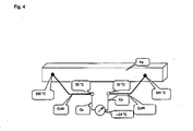
- FIG. 6 A typical combustion boiler is shown with a furnace (31), the first radiation train (32), the second radiation train (33) and the third radiation train (34) and a convective train (35).
- the firebox (31) is in Essentially limited by the feeder (36), the blanket (37), the Ausbranddecke (38), the side walls of the firebox (39) and the grate (41a-e).
- the fuel supply ertoigt over the refuse supply (40) and the meter (36).
- the combustion takes place on the combustion grate (41a-e), which in this example is subdivided into 5 grate zones, which can be driven individually or together.
- the burnt slag falls after the grate (41) into the slag trap chute (42) to the slagger.
- the primary air (43 ae) is supplied separately through the grate zones (41a-e):
- the secondary air (44 ad) is used for mixing and safer burnout of the gases before entering the first Strahlungszug (32). In modern plants, the secondary air is injected on the forehead and burnout side in 2 levels. The approach and support burners (24) are installed above the secondary air injection (44 ad).
- the walls of the first radiation train can be delivered to meet the minimum combustion conditions and to protect the heating surfaces against corrosion in the lower area with refractory lining (45).
- the membrane walls (29) above the refractory lining (45) in the first radiation train (32) and partly in the second radiation train (33) can be protected against corrosion by welding on nickel-base alloys (47). Thereafter, at the usual boiling water temperatures of 240 to 320 ° C and the lowered flue gas temperatures usually no corrosion protection measures in the lower part of the second train (33) and in the third train (34) are required.
- the flue gases usually cool from the inlet (48) in the first train (32) with 1000- 1300 ° C until leaving the third train (34) to 450- 650 ° C and enter with these temperatures in the convective train (35 ) one.
- the flue gases on a protective evaporator (49), superheaters (20), evaporators (21) and economizers (22) cool to 180-230 ° C and leave the boiler through the exhaust duct (23).
- Fig. 6 Boiler contour with complete assembly of the heat flow sensors, which are used to determine the difference in temperature and temperature profiles mentioned in claims 4, 10, 11 and 12.
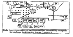
- Fig. 6a Extract from FIG. 6 , Heat flow measurements for determining the position of the fuel before the allocator via grate zone 31, according to claim 6.
- Fig. 6b Extract from FIG. 6 , Heat flux measurements for determining the position of the fire in the combustion system according to claim 5.
- Fig. 6c Extract from FIG. 6 , Heat flow measurements for determining the position of the fire in the Ausbrandzone, according to claim 8.
- Fig. 6d Extract from FIG. 6 , Heat flow measurements for determining the state of the refractory lining, according to claim 9.
- the essential regulation is the firing performance adjustment, which has different objectives. Legally prescribed is a safe burnout of slag and flue gases at minimum temperatures andwithverweil documentation. In addition, there are intensive efforts to make the operation of the plant as even as possible despite different compositions of the fuel, this objective can contradict the first-mentioned legal requirements can be - in simple terms - for a stable steam output or for decide a stable combustion performance. With stable steam output, steam is the essential guide that regulates combustion performance through the combustion output control. Since the information of the steam flow rate is significantly delayed compared to the actual combustion performance in the firing capacity control, more information from the operation is provided. Up to now, the ceiling temperature measurement and the oxygen content in the flue gas in the area of the economizer are preferably used. In future, the information of the heat measurements can be used to advantage.
- the oxygen consumption (product of the oxygen change and the amount of air supplied) and thus the chemical combustion performance is kept constant for the same amount of air.
- the scheme is eligible for any measure, from the withdrawal of the power to the increase of the air preheating. The decision is made by the control program according to the specification of the optimization condition.
Landscapes
- Physics & Mathematics (AREA)
- General Physics & Mathematics (AREA)
- Chemical & Material Sciences (AREA)
- Engineering & Computer Science (AREA)
- Combustion & Propulsion (AREA)
- Investigating Or Analyzing Materials Using Thermal Means (AREA)
- Separation Using Semi-Permeable Membranes (AREA)
- Incineration Of Waste (AREA)
- Investigating Or Analysing Materials By The Use Of Chemical Reactions (AREA)
Priority Applications (1)
| Application Number | Priority Date | Filing Date | Title |
|---|---|---|---|
| PL08021894T PL2042845T3 (pl) | 2005-08-24 | 2006-08-22 | Sposób i urządzenie do rejestracji gęstości strumienia cieplnego na ścianie membranowej celem optymalizacji układu kotła i eksploatacji kotła |
Applications Claiming Priority (2)
| Application Number | Priority Date | Filing Date | Title |
|---|---|---|---|
| DE102005040277.1A DE102005040277B4 (de) | 2005-08-24 | 2005-08-24 | Vorrichtung zur Erfassung des spezifischen Wärmeflusses auf einer Membranwand zur Optimierung der Kesselauslegung und des Kesselbetriebes |
| EP06017393A EP1760441B1 (de) | 2005-08-24 | 2006-08-22 | Vorrichtung und ein entsprechendes Verfahren zur Erfassung des spezifischen Wärmeflusses auf eine Membranwand zur Optimierung der Kesselauslegung und des Kesselbetriebes |
Related Parent Applications (2)
| Application Number | Title | Priority Date | Filing Date |
|---|---|---|---|
| EP06017393A Division EP1760441B1 (de) | 2005-08-24 | 2006-08-22 | Vorrichtung und ein entsprechendes Verfahren zur Erfassung des spezifischen Wärmeflusses auf eine Membranwand zur Optimierung der Kesselauslegung und des Kesselbetriebes |
| EP06017393.7 Division | 2006-08-22 |
Publications (2)
| Publication Number | Publication Date |
|---|---|
| EP2042845A1 EP2042845A1 (de) | 2009-04-01 |
| EP2042845B1 true EP2042845B1 (de) | 2011-05-18 |
Family
ID=37622310
Family Applications (2)
| Application Number | Title | Priority Date | Filing Date |
|---|---|---|---|
| EP08021894A Active EP2042845B1 (de) | 2005-08-24 | 2006-08-22 | Vorrichtung und Verfahren zur Erfassung des spezifischen Wärmeflusses auf eine Membranwand zur Optimierung der Kesselauslegung und des Kesselbetriebes |
| EP06017393A Active EP1760441B1 (de) | 2005-08-24 | 2006-08-22 | Vorrichtung und ein entsprechendes Verfahren zur Erfassung des spezifischen Wärmeflusses auf eine Membranwand zur Optimierung der Kesselauslegung und des Kesselbetriebes |
Family Applications After (1)
| Application Number | Title | Priority Date | Filing Date |
|---|---|---|---|
| EP06017393A Active EP1760441B1 (de) | 2005-08-24 | 2006-08-22 | Vorrichtung und ein entsprechendes Verfahren zur Erfassung des spezifischen Wärmeflusses auf eine Membranwand zur Optimierung der Kesselauslegung und des Kesselbetriebes |
Country Status (7)
| Country | Link |
|---|---|
| EP (2) | EP2042845B1 (pl) |
| AT (2) | ATE418068T1 (pl) |
| DE (2) | DE102005040277B4 (pl) |
| DK (2) | DK2042845T3 (pl) |
| ES (2) | ES2320165T3 (pl) |
| PL (2) | PL2042845T3 (pl) |
| PT (1) | PT1760441E (pl) |
Families Citing this family (13)
| Publication number | Priority date | Publication date | Assignee | Title |
|---|---|---|---|---|
| DE102009009592A1 (de) * | 2009-02-19 | 2010-08-26 | Clyde Bergemann Gmbh Maschinen- Und Apparatebau | Messeinrichtung für einen Wärmetauscher |
| DE102009021600B4 (de) | 2009-05-15 | 2015-10-01 | Chemin Gmbh | Vorrichtung und Verfahren zur Erfassung des spezifischen Wärmeflusses |
| DE102010048063A1 (de) | 2010-10-12 | 2012-04-12 | Chemin Gmbh | Verfahren zur Charakterisierung von Belagseigenschaften auf Wärmeübertragungsflächen in Dampferzeugern |
| DE102011108327A1 (de) | 2011-07-25 | 2013-01-31 | Clyde Bergemann Gmbh Maschinen- Und Apparatebau | Verfahren zur Erhöhung des Wirkungsgrades einer Verbrennungsanlage, insbesondere eines Müllverbrennungs- oder Biomassekraftwerkes |
| CN103077330B (zh) * | 2013-02-27 | 2016-01-06 | 中国矿业大学(北京) | 存在垂向水量交换情况下的地下水全局流线可视化方法 |
| CN104498699A (zh) * | 2014-11-25 | 2015-04-08 | 西安热工研究院有限公司 | 一种锅炉膜式水冷壁局部焊后热处理装置和工艺 |
| CN106092353A (zh) * | 2016-07-21 | 2016-11-09 | 安徽蓝润自动化仪表有限公司 | 一种耐腐蚀防断裂热电偶 |
| DE102016214854B4 (de) | 2016-08-10 | 2020-02-13 | Technische Universität Dresden | Verfahren und Vorrichtung zur Charakterisierung von Ablagerungen |
| CN107490000B (zh) * | 2017-08-28 | 2019-03-08 | 北京航空航天大学 | 一种电站锅炉异种钢接头部位的壁温监测方法和系统 |
| CN108731847A (zh) * | 2018-06-01 | 2018-11-02 | 中国神华能源股份有限公司 | 热流计、锅炉及热流计检测方法 |
| DE102020116607A1 (de) | 2020-06-24 | 2021-12-30 | Technische Universität Dresden, Körperschaft des öffentlichen Rechts | Vorrichtung und Verfahren zum Bestimmen eines spezifischen Wärmestroms |
| CN113290221A (zh) * | 2021-05-27 | 2021-08-24 | 中冶赛迪工程技术股份有限公司 | 一种板坯连铸结晶器热流检测装置及方法 |
| CN114964565B (zh) * | 2022-05-25 | 2025-07-22 | 中国计量大学 | 一种面向差示扫描量热的立体型热流传感器及其制备工艺 |
Family Cites Families (3)
| Publication number | Priority date | Publication date | Assignee | Title |
|---|---|---|---|---|
| US4779994A (en) * | 1987-10-15 | 1988-10-25 | Virginia Polytechnic Institute And State University | Heat flux gage |
| US6485174B1 (en) * | 2000-10-27 | 2002-11-26 | The Babcock & Wilcox Company | Attachable heat flux measuring device |
| DE10248312A1 (de) * | 2002-10-16 | 2004-04-29 | Clyde Bergemann Gmbh | Wärmeflussmesseinrichtung für Druckrohr sowie Verfahren zum Messen eines Wärmeflusses durch Druckrohre |
-
2005
- 2005-08-24 DE DE102005040277.1A patent/DE102005040277B4/de not_active Expired - Fee Related
-
2006
- 2006-08-22 DE DE502006002364T patent/DE502006002364D1/de active Active
- 2006-08-22 PT PT06017393T patent/PT1760441E/pt unknown
- 2006-08-22 DK DK08021894.4T patent/DK2042845T3/da active
- 2006-08-22 DK DK06017393T patent/DK1760441T3/da active
- 2006-08-22 AT AT06017393T patent/ATE418068T1/de active
- 2006-08-22 ES ES06017393T patent/ES2320165T3/es active Active
- 2006-08-22 AT AT08021894T patent/ATE510198T1/de active
- 2006-08-22 EP EP08021894A patent/EP2042845B1/de active Active
- 2006-08-22 EP EP06017393A patent/EP1760441B1/de active Active
- 2006-08-22 ES ES08021894T patent/ES2366679T3/es active Active
- 2006-08-22 PL PL08021894T patent/PL2042845T3/pl unknown
- 2006-08-22 PL PL06017393T patent/PL1760441T3/pl unknown
Also Published As
| Publication number | Publication date |
|---|---|
| ES2366679T3 (es) | 2011-10-24 |
| DE102005040277B4 (de) | 2015-11-05 |
| EP2042845A1 (de) | 2009-04-01 |
| ATE418068T1 (de) | 2009-01-15 |
| PL2042845T3 (pl) | 2012-01-31 |
| ATE510198T1 (de) | 2011-06-15 |
| EP1760441A1 (de) | 2007-03-07 |
| PT1760441E (pt) | 2009-03-24 |
| DE502006002364D1 (de) | 2009-01-29 |
| DK1760441T3 (da) | 2009-04-14 |
| PL1760441T3 (pl) | 2009-06-30 |
| EP1760441B1 (de) | 2008-12-17 |
| ES2320165T3 (es) | 2009-05-19 |
| DE102005040277A1 (de) | 2007-03-01 |
| DK2042845T3 (da) | 2011-09-12 |
Similar Documents
| Publication | Publication Date | Title |
|---|---|---|
| EP2042845B1 (de) | Vorrichtung und Verfahren zur Erfassung des spezifischen Wärmeflusses auf eine Membranwand zur Optimierung der Kesselauslegung und des Kesselbetriebes | |
| DE112010003028B4 (de) | Verfahren und Vorrichtung zur Unterdrückung von Ascheanhaftung in einem Kessel | |
| French | Metallurgical failures in fossil fired boilers | |
| EP2423584B1 (de) | Dampferzeuger zur Erzeugung von überhitztem Dampf in einer Abfallverbrennungsanlage | |
| KR20130044294A (ko) | 가열로의 회 부착 억제 방법 및 회 부착 억제 장치 | |
| EP2992312B1 (de) | Vorrichtung und verfahren zur messung der veränderung von werkstoffen durch gasströme | |
| Kain et al. | Failure of carbon steel tubes in a fluidized bed combustor | |
| JP2019105393A (ja) | 廃棄物焼却炉ボイラの閉塞および腐食の抑制方法 | |
| Wright et al. | Possible scenarios for the causes of accelerated fireside corrosion of superheater tubes in coal-fired boilers | |
| DE102011108327A1 (de) | Verfahren zur Erhöhung des Wirkungsgrades einer Verbrennungsanlage, insbesondere eines Müllverbrennungs- oder Biomassekraftwerkes | |
| EP2028464B1 (de) | Verfahren zur Ermittlung und Überwachung des Materialerschöpfungsgrades der Rohre von Heizflächen in mit fossilen Brennstoffen befeuerten Dampferzeugungsanlagen | |
| Lai | Fireside corrosion and erosion/corrosion protection in coal-fired boilers | |
| Kung et al. | Corrosion Resistance of Four Iron-base Alloys for the Waterwall of Low-NOx Cyclone Boilers | |
| WO2021259422A1 (de) | Vorrichtung und verfahren zum bestimmen eines spezifischen wärmestroms | |
| EP0058233A2 (de) | Verfahren und Vorrichtung zur Detektion von Natrium-Leckagen in Dampferzeugern | |
| Oh et al. | Effects of ash fouling on heat transfer during combustion of cattle biomass in a small‐scale boiler burner facility under unsteady transition conditions | |
| Hack et al. | Effects of fuel composition and temperature on fireside corrosion resistance of materials for advanced ultrasupercritical coal fired power plants | |
| Adams et al. | Seghers boiler prism: a proven primary measure against high temperature boiler corrosion | |
| White | Superheater/intermediate temperature air heater tube corrosion tests in the MHD coal fired flow facility (Montana Rosebud POC tests) | |
| DE102005039243B4 (de) | Verfahren zur Ermittlung eines kritischen Verschlakungsbereiches an den Heizflächenwänden der Brennkammer einer Kohlenstaubfeuerung | |
| Moloko | Investigation of the Mechanisms and Control Measures for Fireside Corrosion in Eskom Fossil Fuel Boilers | |
| EP3193082B1 (de) | Verfahren und vorrichtung zur erzeugung von überhitztem dampf mittels der im kessel einer verbrennungsanlage erzeugten wärme | |
| DE102006012269B4 (de) | Verfahren zur Reduzierung salzinduzierter Korrosionen und Belagbildungen in Verbrennungsanlagen sowie eine Vorrichtung zur Durchführung des Verfahrens | |
| DE1473246C (de) | Strahlungspyrometer mit Thermoelemen ten | |
| Scholey | A transient, three-dimensional, thermal model of a billet reheating furnace |
Legal Events
| Date | Code | Title | Description |
|---|---|---|---|
| PUAI | Public reference made under article 153(3) epc to a published international application that has entered the european phase |
Free format text: ORIGINAL CODE: 0009012 |
|
| AC | Divisional application: reference to earlier application |
Ref document number: 1760441 Country of ref document: EP Kind code of ref document: P |
|
| AK | Designated contracting states |
Kind code of ref document: A1 Designated state(s): AT BE BG CH CY CZ DE DK EE ES FI FR GB GR HU IE IS IT LI LT LU LV MC NL PL PT RO SE SI SK TR |
|
| AX | Request for extension of the european patent |
Extension state: AL BA HR MK RS |
|
| RIN1 | Information on inventor provided before grant (corrected) |
Inventor name: KRUEGER, SASCHA Inventor name: BECKMANN, MICHAEL Inventor name: SPIEGEL, WOLFGANG Inventor name: KRUEGER, JOERG |
|
| RIN1 | Information on inventor provided before grant (corrected) |
Inventor name: KRUEGER, SASCHA Inventor name: BECKMANN, MICHAEL Inventor name: SPIEGEL, WOLFGANG Inventor name: KRUEGER, JOERG |
|
| 17P | Request for examination filed |
Effective date: 20090730 |
|
| AKX | Designation fees paid |
Designated state(s): AT BE BG CH CY CZ DE DK EE ES FI FR GB GR HU IE IS IT LI LT LU LV MC NL PL PT RO SE SI SK TR |
|
| 17Q | First examination report despatched |
Effective date: 20100311 |
|
| R17C | First examination report despatched (corrected) |
Effective date: 20100325 |
|
| RTI1 | Title (correction) |
Free format text: DEVICE AND METHOD FOR MEASURING THE SPECIFIC HEAT FLOW ON A MEMBRANE WALL FOR OPTIMISING THE BOILER LAYOUT AND THE BOILER OPERATION |
|
| GRAP | Despatch of communication of intention to grant a patent |
Free format text: ORIGINAL CODE: EPIDOSNIGR1 |
|
| RIN1 | Information on inventor provided before grant (corrected) |
Inventor name: DIPL. ING. KRUEGER, SASCHA Inventor name: PROF. DR.-ING. BECKMANN, MICHAEL Inventor name: DR. SPIEGEL, WOLFGANG Inventor name: DR. KRUEGER, JOERG |
|
| GRAS | Grant fee paid |
Free format text: ORIGINAL CODE: EPIDOSNIGR3 |
|
| GRAA | (expected) grant |
Free format text: ORIGINAL CODE: 0009210 |
|
| REG | Reference to a national code |
Ref country code: GB Ref legal event code: FG4D Free format text: NOT ENGLISH |
|
| REG | Reference to a national code |
Ref country code: CH Ref legal event code: EP |
|
| REG | Reference to a national code |
Ref country code: IE Ref legal event code: FG4D Free format text: LANGUAGE OF EP DOCUMENT: GERMAN |
|
| REG | Reference to a national code |
Ref country code: DE Ref legal event code: R096 Ref document number: 502006009546 Country of ref document: DE Effective date: 20110630 |
|
| REG | Reference to a national code |
Ref country code: NL Ref legal event code: T3 |
|
| REG | Reference to a national code |
Ref country code: SE Ref legal event code: TRGR |
|
| REG | Reference to a national code |
Ref country code: DK Ref legal event code: T3 |
|
| REG | Reference to a national code |
Ref country code: ES Ref legal event code: FG2A Ref document number: 2366679 Country of ref document: ES Kind code of ref document: T3 Effective date: 20111024 |
|
| PG25 | Lapsed in a contracting state [announced via postgrant information from national office to epo] |
Ref country code: LT Free format text: LAPSE BECAUSE OF FAILURE TO SUBMIT A TRANSLATION OF THE DESCRIPTION OR TO PAY THE FEE WITHIN THE PRESCRIBED TIME-LIMIT Effective date: 20110518 Ref country code: PT Free format text: LAPSE BECAUSE OF FAILURE TO SUBMIT A TRANSLATION OF THE DESCRIPTION OR TO PAY THE FEE WITHIN THE PRESCRIBED TIME-LIMIT Effective date: 20110919 |
|
| RAP2 | Party data changed (patent owner data changed or rights of a patent transferred) |
Owner name: CHEMIN GMBH |
|
| PG25 | Lapsed in a contracting state [announced via postgrant information from national office to epo] |
Ref country code: IS Free format text: LAPSE BECAUSE OF FAILURE TO SUBMIT A TRANSLATION OF THE DESCRIPTION OR TO PAY THE FEE WITHIN THE PRESCRIBED TIME-LIMIT Effective date: 20110918 Ref country code: LV Free format text: LAPSE BECAUSE OF FAILURE TO SUBMIT A TRANSLATION OF THE DESCRIPTION OR TO PAY THE FEE WITHIN THE PRESCRIBED TIME-LIMIT Effective date: 20110518 Ref country code: SI Free format text: LAPSE BECAUSE OF FAILURE TO SUBMIT A TRANSLATION OF THE DESCRIPTION OR TO PAY THE FEE WITHIN THE PRESCRIBED TIME-LIMIT Effective date: 20110518 Ref country code: GR Free format text: LAPSE BECAUSE OF FAILURE TO SUBMIT A TRANSLATION OF THE DESCRIPTION OR TO PAY THE FEE WITHIN THE PRESCRIBED TIME-LIMIT Effective date: 20110819 Ref country code: CY Free format text: LAPSE BECAUSE OF FAILURE TO SUBMIT A TRANSLATION OF THE DESCRIPTION OR TO PAY THE FEE WITHIN THE PRESCRIBED TIME-LIMIT Effective date: 20110518 |
|
| REG | Reference to a national code |
Ref country code: IE Ref legal event code: FD4D |
|
| PG25 | Lapsed in a contracting state [announced via postgrant information from national office to epo] |
Ref country code: IE Free format text: LAPSE BECAUSE OF FAILURE TO SUBMIT A TRANSLATION OF THE DESCRIPTION OR TO PAY THE FEE WITHIN THE PRESCRIBED TIME-LIMIT Effective date: 20110518 Ref country code: CZ Free format text: LAPSE BECAUSE OF FAILURE TO SUBMIT A TRANSLATION OF THE DESCRIPTION OR TO PAY THE FEE WITHIN THE PRESCRIBED TIME-LIMIT Effective date: 20110518 Ref country code: EE Free format text: LAPSE BECAUSE OF FAILURE TO SUBMIT A TRANSLATION OF THE DESCRIPTION OR TO PAY THE FEE WITHIN THE PRESCRIBED TIME-LIMIT Effective date: 20110518 |
|
| REG | Reference to a national code |
Ref country code: PL Ref legal event code: T3 |
|
| PG25 | Lapsed in a contracting state [announced via postgrant information from national office to epo] |
Ref country code: RO Free format text: LAPSE BECAUSE OF FAILURE TO SUBMIT A TRANSLATION OF THE DESCRIPTION OR TO PAY THE FEE WITHIN THE PRESCRIBED TIME-LIMIT Effective date: 20110518 Ref country code: SK Free format text: LAPSE BECAUSE OF FAILURE TO SUBMIT A TRANSLATION OF THE DESCRIPTION OR TO PAY THE FEE WITHIN THE PRESCRIBED TIME-LIMIT Effective date: 20110518 |
|
| PLBE | No opposition filed within time limit |
Free format text: ORIGINAL CODE: 0009261 |
|
| STAA | Information on the status of an ep patent application or granted ep patent |
Free format text: STATUS: NO OPPOSITION FILED WITHIN TIME LIMIT |
|
| PG25 | Lapsed in a contracting state [announced via postgrant information from national office to epo] |
Ref country code: MC Free format text: LAPSE BECAUSE OF NON-PAYMENT OF DUE FEES Effective date: 20110831 |
|
| 26N | No opposition filed |
Effective date: 20120221 |
|
| REG | Reference to a national code |
Ref country code: DE Ref legal event code: R097 Ref document number: 502006009546 Country of ref document: DE Effective date: 20120221 |
|
| PG25 | Lapsed in a contracting state [announced via postgrant information from national office to epo] |
Ref country code: LU Free format text: LAPSE BECAUSE OF NON-PAYMENT OF DUE FEES Effective date: 20110822 |
|
| PG25 | Lapsed in a contracting state [announced via postgrant information from national office to epo] |
Ref country code: BG Free format text: LAPSE BECAUSE OF FAILURE TO SUBMIT A TRANSLATION OF THE DESCRIPTION OR TO PAY THE FEE WITHIN THE PRESCRIBED TIME-LIMIT Effective date: 20110818 |
|
| PG25 | Lapsed in a contracting state [announced via postgrant information from national office to epo] |
Ref country code: TR Free format text: LAPSE BECAUSE OF FAILURE TO SUBMIT A TRANSLATION OF THE DESCRIPTION OR TO PAY THE FEE WITHIN THE PRESCRIBED TIME-LIMIT Effective date: 20110518 |
|
| PG25 | Lapsed in a contracting state [announced via postgrant information from national office to epo] |
Ref country code: HU Free format text: LAPSE BECAUSE OF FAILURE TO SUBMIT A TRANSLATION OF THE DESCRIPTION OR TO PAY THE FEE WITHIN THE PRESCRIBED TIME-LIMIT Effective date: 20110518 |
|
| REG | Reference to a national code |
Ref country code: FR Ref legal event code: PLFP Year of fee payment: 11 |
|
| REG | Reference to a national code |
Ref country code: FR Ref legal event code: PLFP Year of fee payment: 12 |
|
| REG | Reference to a national code |
Ref country code: FR Ref legal event code: PLFP Year of fee payment: 13 |
|
| REG | Reference to a national code |
Ref country code: DE Ref legal event code: R082 Ref document number: 502006009546 Country of ref document: DE Representative=s name: SCHLOSSER, MARTIN, DIPL.-PHYS. DIPL.-BETRIEBSW, DE Ref country code: DE Ref legal event code: R082 Ref document number: 502006009546 Country of ref document: DE |
|
| REG | Reference to a national code |
Ref country code: DE Ref legal event code: R082 Ref document number: 502006009546 Country of ref document: DE Representative=s name: SCHLOSSER, MARTIN, DIPL.-PHYS. DIPL.-BETRIEBSW, DE |
|
| REG | Reference to a national code |
Ref country code: DE Ref legal event code: R082 Ref document number: 502006009546 Country of ref document: DE Representative=s name: SCHLOSSER, MARTIN, DIPL.-PHYS. DIPL.-BETRIEBSW, DE |
|
| PGFP | Annual fee paid to national office [announced via postgrant information from national office to epo] |
Ref country code: NL Payment date: 20230823 Year of fee payment: 18 |
|
| PGFP | Annual fee paid to national office [announced via postgrant information from national office to epo] |
Ref country code: IT Payment date: 20230831 Year of fee payment: 18 Ref country code: GB Payment date: 20230824 Year of fee payment: 18 Ref country code: FI Payment date: 20230823 Year of fee payment: 18 Ref country code: ES Payment date: 20230918 Year of fee payment: 18 Ref country code: CH Payment date: 20230902 Year of fee payment: 18 Ref country code: AT Payment date: 20230818 Year of fee payment: 18 |
|
| PGFP | Annual fee paid to national office [announced via postgrant information from national office to epo] |
Ref country code: SE Payment date: 20230823 Year of fee payment: 18 Ref country code: PL Payment date: 20230810 Year of fee payment: 18 Ref country code: FR Payment date: 20230821 Year of fee payment: 18 Ref country code: DK Payment date: 20230823 Year of fee payment: 18 Ref country code: DE Payment date: 20230831 Year of fee payment: 18 Ref country code: BE Payment date: 20230822 Year of fee payment: 18 |
|
| REG | Reference to a national code |
Ref country code: DE Ref legal event code: R119 Ref document number: 502006009546 Country of ref document: DE |
|
| REG | Reference to a national code |
Ref country code: DK Ref legal event code: EBP Effective date: 20240831 |
|
| REG | Reference to a national code |
Ref country code: CH Ref legal event code: PL |
|
| REG | Reference to a national code |
Ref country code: SE Ref legal event code: EUG |
|
| REG | Reference to a national code |
Ref country code: NL Ref legal event code: MM Effective date: 20240901 |
|
| PG25 | Lapsed in a contracting state [announced via postgrant information from national office to epo] |
Ref country code: FI Free format text: LAPSE BECAUSE OF NON-PAYMENT OF DUE FEES Effective date: 20240822 |
|
| REG | Reference to a national code |
Ref country code: AT Ref legal event code: MM01 Ref document number: 510198 Country of ref document: AT Kind code of ref document: T Effective date: 20240822 |
|
| GBPC | Gb: european patent ceased through non-payment of renewal fee |
Effective date: 20240822 |
|
| PG25 | Lapsed in a contracting state [announced via postgrant information from national office to epo] |
Ref country code: AT Free format text: LAPSE BECAUSE OF NON-PAYMENT OF DUE FEES Effective date: 20240822 Ref country code: CH Free format text: LAPSE BECAUSE OF NON-PAYMENT OF DUE FEES Effective date: 20240831 |
|
| PG25 | Lapsed in a contracting state [announced via postgrant information from national office to epo] |
Ref country code: NL Free format text: LAPSE BECAUSE OF NON-PAYMENT OF DUE FEES Effective date: 20240901 |
|
| REG | Reference to a national code |
Ref country code: BE Ref legal event code: MM Effective date: 20240831 |
|
| PG25 | Lapsed in a contracting state [announced via postgrant information from national office to epo] |
Ref country code: DE Free format text: LAPSE BECAUSE OF NON-PAYMENT OF DUE FEES Effective date: 20250301 |
|
| PG25 | Lapsed in a contracting state [announced via postgrant information from national office to epo] |
Ref country code: DK Free format text: LAPSE BECAUSE OF NON-PAYMENT OF DUE FEES Effective date: 20240831 Ref country code: GB Free format text: LAPSE BECAUSE OF NON-PAYMENT OF DUE FEES Effective date: 20240822 |
|
| PG25 | Lapsed in a contracting state [announced via postgrant information from national office to epo] |
Ref country code: BE Free format text: LAPSE BECAUSE OF NON-PAYMENT OF DUE FEES Effective date: 20240831 Ref country code: IT Free format text: LAPSE BECAUSE OF NON-PAYMENT OF DUE FEES Effective date: 20240822 |
|
| PG25 | Lapsed in a contracting state [announced via postgrant information from national office to epo] |
Ref country code: FR Free format text: LAPSE BECAUSE OF NON-PAYMENT OF DUE FEES Effective date: 20240831 |
|
| REG | Reference to a national code |
Ref country code: ES Ref legal event code: FD2A Effective date: 20250930 |
|
| PG25 | Lapsed in a contracting state [announced via postgrant information from national office to epo] |
Ref country code: ES Free format text: LAPSE BECAUSE OF NON-PAYMENT OF DUE FEES Effective date: 20240823 |
|
| PG25 | Lapsed in a contracting state [announced via postgrant information from national office to epo] |
Ref country code: SE Free format text: LAPSE BECAUSE OF NON-PAYMENT OF DUE FEES Effective date: 20240823 |
|
| PG25 | Lapsed in a contracting state [announced via postgrant information from national office to epo] |
Ref country code: PL Free format text: LAPSE BECAUSE OF NON-PAYMENT OF DUE FEES Effective date: 20240822 |