EP2041698B1 - Datenkarteneinführeinrichtung - Google Patents
Datenkarteneinführeinrichtung Download PDFInfo
- Publication number
- EP2041698B1 EP2041698B1 EP07786978A EP07786978A EP2041698B1 EP 2041698 B1 EP2041698 B1 EP 2041698B1 EP 07786978 A EP07786978 A EP 07786978A EP 07786978 A EP07786978 A EP 07786978A EP 2041698 B1 EP2041698 B1 EP 2041698B1
- Authority
- EP
- European Patent Office
- Prior art keywords
- data card
- sealing element
- insertion device
- card insertion
- slot
- Prior art date
- Legal status (The legal status is an assumption and is not a legal conclusion. Google has not performed a legal analysis and makes no representation as to the accuracy of the status listed.)
- Not-in-force
Links
Images

Classifications
-
- G—PHYSICS
- G06—COMPUTING OR CALCULATING; COUNTING
- G06K—GRAPHICAL DATA READING; PRESENTATION OF DATA; RECORD CARRIERS; HANDLING RECORD CARRIERS
- G06K13/00—Conveying record carriers from one station to another, e.g. from stack to punching mechanism
- G06K13/02—Conveying record carriers from one station to another, e.g. from stack to punching mechanism the record carrier having longitudinal dimension comparable with transverse dimension, e.g. punched card
- G06K13/08—Feeding or discharging cards
-
- G—PHYSICS
- G06—COMPUTING OR CALCULATING; COUNTING
- G06K—GRAPHICAL DATA READING; PRESENTATION OF DATA; RECORD CARRIERS; HANDLING RECORD CARRIERS
- G06K13/00—Conveying record carriers from one station to another, e.g. from stack to punching mechanism
- G06K13/02—Conveying record carriers from one station to another, e.g. from stack to punching mechanism the record carrier having longitudinal dimension comparable with transverse dimension, e.g. punched card
- G06K13/08—Feeding or discharging cards
- G06K13/0868—Feeding or discharging cards using an arrangement for keeping the feeding or insertion slot of the card station clean of dirt, or to avoid feeding of foreign or unwanted objects into the slot
- G06K13/0875—Feeding or discharging cards using an arrangement for keeping the feeding or insertion slot of the card station clean of dirt, or to avoid feeding of foreign or unwanted objects into the slot the arrangement comprising a shutter for blocking at least part of the card insertion slot
-
- G—PHYSICS
- G07—CHECKING-DEVICES
- G07C—TIME OR ATTENDANCE REGISTERS; REGISTERING OR INDICATING THE WORKING OF MACHINES; GENERATING RANDOM NUMBERS; VOTING OR LOTTERY APPARATUS; ARRANGEMENTS, SYSTEMS OR APPARATUS FOR CHECKING NOT PROVIDED FOR ELSEWHERE
- G07C5/00—Registering or indicating the working of vehicles
- G07C5/08—Registering or indicating performance data other than driving, working, idle, or waiting time, with or without registering driving, working, idle or waiting time
- G07C5/0841—Registering performance data
- G07C5/085—Registering performance data using electronic data carriers
- G07C5/0858—Registering performance data using electronic data carriers wherein the data carrier is removable
-
- G—PHYSICS
- G07—CHECKING-DEVICES
- G07C—TIME OR ATTENDANCE REGISTERS; REGISTERING OR INDICATING THE WORKING OF MACHINES; GENERATING RANDOM NUMBERS; VOTING OR LOTTERY APPARATUS; ARRANGEMENTS, SYSTEMS OR APPARATUS FOR CHECKING NOT PROVIDED FOR ELSEWHERE
- G07C7/00—Details or accessories common to the registering or indicating apparatus of groups G07C3/00 and G07C5/00
Definitions
- the invention relates to a registreincream adopted, in particular for a tachograph .eines motor vehicle, having a slot-like receiving opening having a front panel through which a data card is inserted, with a arranged behind the insertion of the data card sealing device, which arranged in the insertion behind the receiving opening Insertion slot for the sealed insertion of the data card, wherein the sealing means comprises a one-piece, plate-like sealing element made of an elastic material in which the insertion slot is like a cut formed by the elasticity of the material of the sealing element, wherein at one or both of the insertion slot parallel end portions of the sealing element and / or at one or both end regions of the insertion slot on the sealing element, one or two fastening arms extending in the insertion direction are arranged, which at one or more n housing parts of the housing of the data card insertion device can be fastened.
- the sealing means comprises a resiliently mounted lower elastic member which is biased to an upper sealing element in abutment. Between the elastic element and the sealing element, the data card can be guided while displacing the elastic element and forming the insertion slot.
- the object of the invention is therefore to provide a registreincream raised of the type described above, which consists of a few components, requires only a small footprint and can flow into the penetrating into the insertion slot residual moisture.
- the sealing device consists of a single component, so that only a small space required and easy mounting is possible.
- the plate-like sealing element is also easy to produce.
- the insertion slot When not in the insertion slot data card, the insertion slot is sealed due to the elasticity of the material of the sealing element, without the need for additional spring elements are required.
- the two transversely to the insertion slot extending plate surfaces of the plate-shaped sealing element may be formed parallel to each other.
- one or both plate surfaces may be concave or convex or roof-shaped.
- the length of the insertion slot preferably corresponds to the width of the data card or is only larger by a small amount, so that the data card inserted into the insertion slot is tightly enclosed by the elasticity of the sealing element.
- the elastic material of the sealing element may be a plastic.
- the sealing element is easy to produce when the sealing element is an injection molded part.
- the elastic material of the sealing element may be an elastomer, in particular a thermoplastic elastomer.
- a stability against deformation when pulling out the data card is achieved in that the sealing element can be supported against the insertion direction completely or partially enclosing support frame against the insertion. At the same time, the area surrounding the insertion slot is also sealed so that dirt and moisture are not around the exterior of the sealing element can pass around inside the housing of the data card insertion device.
- the one or more attachment arms may extend across the width of the plate-shaped sealing element.
- the plate-shaped sealing element and the fastening arms are integrally formed.
- the housing part (s) may form part or all of an insertion shaft for insertion of the data card.
- the shaft element can be plugged onto the housing parts designed in accordance with its outer contour.
- the housing parts may have on their outer contour one or more protruding cams which engage in corresponding recesses of the fastening arms or of the shaft element.
- the wall thickness of the attachment arms or the shaft element is a multiple of the wall thickness of the plate-shaped sealing element, wherein the wall thickness of the attachment arms or the shaft element is preferably at least twice the wall thickness of the plate-shaped sealing element.
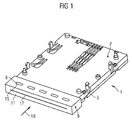
- the illustrated Normallyeingarannoced arthritis pain syndrome has a housing 1, which consists of an upper housing part 2 and a lower housing part 3, which are interconnected.
- an insertion shaft 4 for insertion of a data card 5 is formed.
- the housing 1 At the front, the housing 1 at a distance from the upper and lower housing part 2 and 3, a front panel 6, which has the insertion shaft 4 in a plane opposite a slot-like receiving opening 7.
- the front panel 6 facing the end of the upper and lower housing part 2 and 3 has an outer contour with a transverse rectangular cross-section.
- Both at the top of the upper housing part 2 and at the bottom of the lower housing part 3 is one each Row of five protruding cams 8 rectangular cross section arranged.
- a square tube-like shaft member 9 is attached to the corresponding inner cross section of its inner shaft 10, wherein the front panel side of the shaft 10 is closed by a plate-like sealing element 11.
- the shaft member 9 is pushed to the abutment of its sealing element 11 opposite end of a stop 12 forming a step on the upper and lower housing part 2 and 3.
- the upper wall 13 and the lower wall 14 of the shaft member 9 has according to the cams 8 formed through recesses 15, in which the cam 8 engage with a pushed-shaft element 9.
- Shaft element 9 and sealing element 11 are integrally formed as an injection molded part and consist of a thermoplastic elastomer.
- the wall thickness of the upper and lower walls 13 and 14 of the shaft member 9 is about three times the wall thickness of the sealing member 11, so that the flexibility of the sealing member 11 is greater than the flexibility of the shaft member.
- the shaft element 9 may indeed be pushed under elastic deformation on the cam 8 on the outer contour of the upper and lower housing part 2 and 3 to rest on stop 12, retains after snapping the cam 8 in the recesses 15 but largely its injection molded form at.
- the sealing element 11 has a cut-like continuous insertion slot 17, which extends in the plane of the insertion shaft 4 and which is closed by the elasticity of the material of the sealing element 11 when the data card 5 is not inserted.
- the width of the insertion slot 17 corresponds approximately to the width of the data card. 5
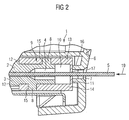
- the data card 5 will, as in FIG. 2 can be seen, introduced through the receiving opening 7 of the front panel 6 and the support frame 16 in the insertion slot 17 and through this into the insertion shaft 4.
- the insertion slot 17 expands elastically according to the data card 5, but remains with elastic bias the data card 5 enclosing close to this in Appendix.
- Residual moisture which nevertheless penetrates through the insertion slot 17, can collect behind the insertion slot 17 and drain via two drainage openings 18 in the lower wall 14 of the shaft element 9.
Landscapes
- Physics & Mathematics (AREA)
- General Physics & Mathematics (AREA)
- Engineering & Computer Science (AREA)
- Theoretical Computer Science (AREA)
- Time Recorders, Dirve Recorders, Access Control (AREA)
- Casings For Electric Apparatus (AREA)
- Connector Housings Or Holding Contact Members (AREA)
- Devices For Checking Fares Or Tickets At Control Points (AREA)
- Gasket Seals (AREA)
Description
- Die Erfindung bezieht sich auf eine Datenkarteneinführeinrichtung, insbesondere für einen Fahrtenschreiber .eines Kraftfahrzeugs, mit einer eine schlitzartige Aufnahmeöffnung aufweisenden Frontblende, durch die eine Datenkarte einführbar ist, mit einer hinter der in Einführrichtung der Datenkarte angeordneten Dichteinrichtung, die einen in Einführrichtung hinter der Aufnahmeöffnung angeordneten Einführschlitz zum abgedichteten Einführen der Datenkarte aufweist, wobei die Dichteinrichtung ein einteiliges, plattenartiges Dichtelement aus einem elastischen Werkstoff aufweist, in dem der Einführschlitz schnittartig, durch die Elastizität des Werkstoffs des Dichtelements schließend ausgebildet ist, wobei an einem oder beiden zum Einführschlitz parallelen Endbereichen des Dichtelements und/oder an einem oder beiden Endbereichen des Einführschlitzes an dem Dichtelement ein oder zwei sich in Einführrichtung erstreckende Befestigungsarme angeordnet sind, die an einem oder mehreren Gehäuseteilen des Gehäuses der Datenkarteneinführeinrichtung befestigbar sind.
- Bei einer derartigen Datenkarteneinführeinrichtung ist es bekannt, dass die Dichteinrichtung ein federnd gelagertes unteres elastisches Element aufweist, das mit Vorspannung an einem oberen Dichtelement in Anlage ist. Zwischen dem elastischen Element und dem Dichtelement ist unter Verdrängung des elastischen Elements und Bildung des Einführschlitzes die Datenkarte hindurchführbar.
- Diese Datenkarteneinführeinrichtung weist eine Vielzahl von Bauteilen auf und erfordert einen großen Platzbedarf.
- Aus der
US 5,265,951 A ist eine Dateneinführeinrichtung der eingangs genannten Art bekannt. - Weiterhin ist aus der
EP 0 281 728 A ist eine Datenkarteneinführeinrichtung bekannt, die eine zweiteilige Dichteinrichtung besitzt, zwischen dessen beiden Teilen ein Einführschlitz gebildet ist. - Aufgabe der Erfindung ist es daher eine Datenkarteneinführeinrichtung der eingangs beschriebenen Art zu schaffen, die aus wenigen Bauteilen besteht, nur einen geringen Platzbedarf erfordert und bei der in den Einführschlitz eindringende Restfeuchtigkeit abfließen kann.
- Diese Aufgabe wird erfindungsgemäß durch eine Datenarteinführeinrichtung nach Anspruch 1 gelöst, wobei insbesondere die Befestigungsarme ein die Gehäuseteile umschließendes, radial umlaufend geschlossenes, an seinem dem plattenförmigen Dichtelement entgegengesetzten Ende offenes Schachtelement bildern, in dessen unterer Wand ein oder mehrere durchgehende Entwässerungsöffnungen ausgebildet sind.
- Durch diese Ausbildung besteht die Dichteinrichtung aus einem einzigen Bauteil, so dass nur ein geringer Bauraum benötigt und eine einfache Montage ermöglicht wird.
- Das plattenartige Dichtelement ist weiterhin auch einfach herstellbar.
- Bei nicht im Einführschlitz befindlicher Datenkarte ist der Einführschlitz aufgrund der Elastizität des Werkstoffes des Dichtelements dicht verschlossen, ohne dass dazu zusätzliche Federelemente erforderlich sind.
- Die beiden sich quer zum Einführschlitz erstreckenden Plattenflächen des plattenförmigen Dichtelements können parallel zueinander ausgebildet sein.
- Es sind aber auch andere, von einer Ebene abweichende Ausgestaltungen einer oder beider Plattenflächen möglich. So können eine oder beide Plattenflächen konkav oder konvex oder auch dachförmig ausgebildet sein.
- Der Übergang vom Einführschlitz des Dichtelements zum Einführschacht wird durch das Schachtelement dicht umschlossen, wobei durch die Entwässerungsöffnungen Reste von Feuchtigkeit, die mit der Datenkarte durch den Einführschlitz hindurchgetreten sind, nach.außen ablaufen können.
- Vorzugsweise entspricht die Länge des Einführschlitzes der Breite der Datenkarte oder ist nur um ein geringes Maß größer, so dass die in den Einführschlitz eingeführte Datenkarte durch die Elastizität des Dichtelements dicht umschlossen ist.
- Dabei kann der elastische Werkstoff des Dichtelements ein Kunststoff sein.
- Das Dichtelement ist einfach herstellbar, wenn das Dichtelement ein Spritzgussteil ist.
- Dazu kann der elastische Werkstoff des Dichtelements ein Elastomer, insbesondere ein thermoplastischer Elastomer sein.
- Eine Erhöhung der Anschmiegbarkeit an die Datenkarte und damit eine Erhöhung der Dichtsicherheit wird dadurch erreicht, dass die einander gegenüberliegenden Längsseiten des Einführschlitzes als einander zugewandte Dichtlippen ausgebildet sind.
- Eine Stabilität gegen Verformung beim Herausziehen der Datenkarte wird dadurch erreicht, dass das Dichtelement an einem den Einführschlitz ganz oder teilweise umschließenden Abstützrahmen entgegen der Einführrichtung abstützbar ist. Gleichzeitig ist auch der den Einführschlitz umgebende Bereich abgedichtet, so dass Schmutz und Feuchtigkeit nicht um das Äußere des Dichtelements herum in das Innere des Gehäuses der Datenkarteneinführeinrichtung gelangen kann.
- Der oder die Befestigungsarme können sich über die Breite des plattenförmigen Dichtelements erstrecken.
- Zur einfachen Herstellung und Verringerung des Montageaufwandes sind vorzugsweise das plattenförmige Dichtelement und die Befestigungsarme einteilig ausgebildet.
- Das oder die Gehäuseteile können ganz oder teilweise einen Einführschacht zum Einführen der Datenkarte bilden.
- Zur einfachen Montage und Befestigung des Schachtelements an den Gehäuseteilen kann das Schachtelement auf die entsprechend seiner Außenkontur ausgebildeten Gehäuseteile aufsteckbar sein.
- Zur einfachen Sicherung des Schachtelements in seiner Einbaulage können die Gehäuseteile an ihrer Außenkontur ein oder mehrere hervorstehende Nocken besitzen, die in entsprechende Ausnehmungen der Befestigungsarme oder des Schachtelements eingreifen.
- Eine weitgehende Formstabilität erhält das Schachtelement dadurch, dass die Wanddicke der Befestigungsarme oder des Schachtelements ein Mehrfaches der Wanddicke des plattenförmigen Dichtelements beträgt, wobei die Wanddicke der Befestigungsarme oder des Schachtelements vorzugsweise mindestens das Zweifache der Wanddicke des plattenförmigen Dichtelements beträgt.
- Ein Ausführungsbeispiel der Erfindung ist in der Zeichnung dargestellt und wird im Folgenden näher beschrieben. Es zeigen:
- Figur 1
- eine perspektivische Ansicht einer Datenkarteneinführeinrichtung,
- Figur 2
- einen Querschnitt eines Ausschnitts der Datenkarteneinführeinrichtung nach
Figur 1 im Einführbereich mit eingeführter Datenkarte, - Figur 3
- den Ausschnitt nach
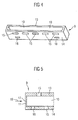
Figur 2 ohne Datenkarte, - Figur 4
- eine perspektivische Rückansicht des Dichtelements mit einem Schachtelement der Datenkarteneinführeinrichtung nach
Figur 1 , - Figur 5
- einen Querschnitt von Dichtelement und Schachtelement nach
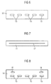
Figur 4 , - Figur 6
- eine Draufsicht von Dichtelement und Schachtelement nach
Figur 4 , - Figur 7
- eine Stirnansicht von Dichtelement und Schachtelement nach
Figur 4 und - Figur 8
- eine Bodenansicht von Dichtelement und Schachtelement nach
Figur 4 . - Die dargestellte Datenkarteneinführeinrichtung für einen Fahrtschreiber eines Kraftfahrzeugs besitzt ein Gehäuse 1, das aus einem oberen Gehäuseteil 2 und einem unteren Gehäuseteil 3 besteht, die miteinander verbunden sind.
- Zwischen den aneinander liegenden Flächen des ersten Gehäuseteils 2 und des zweiten Gehäuseteils 3 ist ein Einführschacht 4 zum Einführen einer Datenkarte 5 ausgebildet.
- Frontseitig weist das Gehäuse 1 in einem Abstand zu oberem und unterem Gehäuseteil 2 und 3 eine Frontblende 6 auf, die dem Einführschacht 4 in einer Ebene gegenüberliegend eine schlitzartige Aufnahmeöffnung 7 besitzt.
- Das der Frontblende 6 zugewandte Ende von oberem und unterem Gehäuseteil 2 und 3 besitzt eine Außenkontur mit einem quer liegendem rechteckigem Querschnitt.
- Sowohl an der Oberseite des oberen Gehäuseteils 2 als auch an der Unterseite des unteren Gehäuseteils 3 ist jeweils eine Reihe von fünf hervorstehenden Nocken 8 rechteckigen Querschnitts angeordnet.
- Auf die Außenkontur mit quer liegendem rechteckigem Querschnitt von oberem und unterem Gehäuseteil 2 und 3 ist ein vierkantrohrartiges Schachtelement 9 mit dem entsprechenden Innenquerschnitt seines inneren Schachts 10 aufgesteckt, wobei frontblendenseitig der Schacht 10 durch ein plattenartiges Dichtelement 11 verschlossen ist.
- Das Schachtelement 9 ist bis zur Anlage seines dem Dichtelement 11 entgegengesetzten Ende an einer einen Anschlag 12 bildenden Stufe an oberem und unterem Gehäuseteil 2 und 3 aufgeschoben.
- Die obere wand 13 und die untere Wand 14 des Schachtelements 9 weist entsprechend den Nocken 8 ausgebildete durchgehende Ausnehmungen 15 auf, in die die Nocken 8 bei aufgeschobenem Schachtelement 9 eingreifen.
- Schachtelement 9 und Dichtelement 11 sind einteilig als Spritzgussteil ausgebildet und bestehen aus einem thermoplastischen Elastomer.
- Die Wanddicke der oberen und unteren Wand 13 und 14 des Schachtelements 9 beträgt etwa das Dreifache der wanddicke des Dichtelements 11, so dass die Flexibilität des Dichtelements 11 größer ist als die Flexibilität des Schachtelements 9.
- Damit kann das Schachtelement 9 zwar unter elastischer Verformung über die Nocken 8 hinweg auf die Außenkontur von oberen und unterem Gehäuseteil 2 und 3 bis zur Anlage am Anschlag 12 aufgeschoben werden, behält nach dem Einrasten der Nocken 8 in die Ausnehmungen 15 aber weitgehend seine spritzgegossene Form bei.
- Nach der Montage von Schachtelement 9 und Dichtelement 11 erfolgt die Montage der Frontblende 6.
- Diese weist einen zum Dichtelement 11 gerichteten Abstützrahmen 16 auf, der mit seiner freien Stirnseite an dem Dichtelement 11 zur Anlage kommt.
- Herstellungstoleranzen von oberem und unterem Gehäuseteil 2 und 3, von Schachtelement 9 und Dichtelement 11 sowie von Frontblende 6 und Abstützrahmen 16 werden dadurch kompensiert, dass der Frontrahmen 16 mit leichter Vorspannung an dem Dichtelement 11 in Anlage ist.
- Das Dichtelement 11 besitzt einen schnittartigen durchgehenden Einführschlitz 17, der sich in der Ebene des Einführschachtes 4 erstreckt und der durch die Elastizität des Werkstoffes des Dichtelements 11 bei nicht eingeführter Datenkarte 5 geschlossen ist.
- Die Breite des Einführschlitzes 17 entspricht etwa der Breite der Datenkarte 5.
- Die Datenkarte 5 wird, wie in
Figur 2 zu sehen ist, durch die Aufnahmeöffnung 7 der Frontblende 6 und den Abstützrahmen 16 in den Einführschlitz 17 und durch diesen in den Einführschacht 4 eingeführt. - Dabei weitet sich der Einführschlitz 17 entsprechend der Datenkarte 5 elastisch auf, bleibt aber mit elastischer Vorspannung die Datenkarte 5 umschließend dicht an dieser in Anlage.
- Dies ermöglicht es die Datenkarteneinführeinrichtung auch bei Geräten wie einem Fahrtenschreiber zu verwenden, bei denen die Datenkarte 5 nicht vollständig in das Gerät eingezogen wird sondern wie in
Figur 2 zu sehen, in eingeführtem Zustand teilweise aus der Datenkarteneinführeinrichtung noch herausragt. - Bei einem Einführen der Datenkarte 5 in Einführrichtung 19 wird durch das mit elastischer Vorspannung an der Datenkarte 5 Anliegen des Dichtelements 11, Schmutz und Feuchtigkeit dichtlippenartig von der Datenkarte 5 abgestreift.
- Restfeuchtigkeit, die dennoch durch den Einführschlitz 17 eindringt, kann sich hinter dem Einführschlitz 17 sammeln und über zwei Entwässerungsöffnungen 18 in der unteren Wand 14 des Schachtelements 9 abfließen.
Claims (14)
- Datenkarteneinführeinrichtung, insbesondere für einen Fahrtenschreiber eines Kraftfahrzeugs, mit einer eine schlitzartige Aufnahmeöffnung aufweisenden Frontblende, durch die eine Datenkarte (5) einführbar ist, mit einer , in Einführrichtung der Datenkarte (5) dahinter angeordneten Dichteinrichtung, die einen in Einführrichtung hinter der Aufnahmeöffnung angeordneten Einführschlitz zum abgedichteten Einführen der Datenkarte (5) aufweist, wobei die Dichteinrichtung ein einteiliges, plattenförmiges Dichtelement (11) aus einem elastischen Werkstoff aufweist, in dem der Einführschlitz (17) schnittartig, durch die Elastizität des Werkstoffs des Dichtelements (11) schließend ausgebildet ist,
wobei an einem oder beiden zum Einführschlitz (17) parallelen Endbereichen des Dichtelements (11) und/oder an einem oder beiden Endbereichen des Einführschlitzes (17) an dem Dichtelement (11) ein oder zwei sich in Einführrichtung (19) erstreckende Befestigungsarme angeordnet sind, die an einem oder mehreren Gehäuseteilen (2, 3) des Gehäuses (1) der Datenkarteneinführeinrichtung befestigbar sind,
dadurch gekennzeichnet,
dass die Befestigungsarme ein die Gehäuseteile (2, 3) umschließendes, radial umlaufend geschlossenes, an seinem dem plattenförmigen Dichtelement (11) entgegengesetzten Ende offenes Schachtelement (9) bilden, in dessen unterer Wand (14) ein oder mehrere durchgehende Entwässerungsöffnungen (18) ausgebildet sind. - Datenkarteneinführeinrichtung nach Anspruch 1, dadurch gekennzeichnet, dass die Länge des Einführschlitzes (17) der Breite der Datenkarte (5) entspricht.
- Datenkarteneinführeinrichtung nach einem der vorhergehenden Ansprüche, dadurch gekennzeichnet, dass der elastische Werkstoff des Dichtelements (11) ein Kunststoff ist.
- Datenkarteneinführeinrichtung nach Anspruch 3, dadurch gekennzeichnet, dass das Dichtelement (11) ein Spritzgussteil ist.
- Datenkarteneinführeinrichtung nach einem der Ansprüche 3 und 4, dadurch gekennzeichnet, dass der elastische Werkstoff des Dichtelements (11) ein Elastomer, insbesondere ein thermoplastischer Elastomer ist.
- Datenkarteneinführeinrichtung nach einem der vorhergehenden Ansprüche, dadurch gekennzeichnet, dass die einander gegenüberliegenden Längsseiten des Einführschlitzes als einander zugewandte Dichtlippen ausgebildet sind.
- Datenkarteneinführeinrichtung nach einem der vorhergehenden Ansprüche, dadurch gekennzeichnet, dass das Dichtelement (11) an einem den Einführschlitz (17) ganz oder teilweise umschließenden Abstützrahmen (16) entgegen der Einführrichtung (19) abstützbar ist.
- Datenkarteneinführeinrichtung nach einem der vorhergehenden Ansprüche, dadurch gekennzeichnet, dass der oder die Befestigungsarme sich über die Breite des plattenförmigen Dichtelements (11) erstrecken.
- Datenkarteneinführeinrichtung nach einem der vorhergehenden Ansprüche, dadurch gekennzeichnet, dass das plattenförmige Dichtelement (11) und die Befestigungsarme einteilig ausgebildet sind.
- Datenkarteneinführeinrichtung nach einem der vorhergehenden Ansprüche, dadurch gekennzeichnet, dass das oder die Gehäuseteile (2, 3) ganz oder teilweise einen Einführschacht (4) zum Einführen der Datenkarte (5) bilden.
- Datenkarteneinführeinrichtung nach einem der vorhergehenden Ansprüche, dadurch gekennzeichnet, dass das Schachtelement (9) auf die entsprechend seiner Außenkontur ausgebildeten Gehäuseteile (2, 3) aufsteckbar ist.
- Datenkarteneinführeinrichtung nach einem der vorhergehenden Ansprüche, dadurch gekennzeichnet, dass die Gehäuseteile (2, 3) an ihrer Außenkontur ein oder mehrere hervorstehende Nocken (8) besitzen, die in entsprechende Ausnehmungen (15) der Befestigungsarme oder des Schachtelements (9) eingreifen.
- Datenkarteneinführeinrichtung nach einem der vorhergehenden Ansprüche, dadurch gekennzeichnet, dass die Wanddicke der Befestigungsarme oder des Schachtelements (9) ein Mehrfaches der Wanddicke des plattenförmigen Dichtelements (11) beträgt.
- Datenkarteneinführeinrichtung nach Anspruch 13, dadurch gekennzeichnet, dass die Wanddicke der Befestigungsarme oder des Schachtelements (9) mindestens das Zweifache der Wanddicke des plattenförmigen Dichtelements (11) beträgt.
Applications Claiming Priority (2)
| Application Number | Priority Date | Filing Date | Title |
|---|---|---|---|
| DE102006030658A DE102006030658A1 (de) | 2006-07-03 | 2006-07-03 | Datenkarteneinführeinrichtung |
| PCT/EP2007/056625 WO2008003668A1 (de) | 2006-07-03 | 2007-07-02 | Datenkarteneinführeinrichtung |
Publications (2)
| Publication Number | Publication Date |
|---|---|
| EP2041698A1 EP2041698A1 (de) | 2009-04-01 |
| EP2041698B1 true EP2041698B1 (de) | 2011-10-19 |
Family
ID=38529674
Family Applications (1)
| Application Number | Title | Priority Date | Filing Date |
|---|---|---|---|
| EP07786978A Not-in-force EP2041698B1 (de) | 2006-07-03 | 2007-07-02 | Datenkarteneinführeinrichtung |
Country Status (10)
| Country | Link |
|---|---|
| US (1) | US8235295B2 (de) |
| EP (1) | EP2041698B1 (de) |
| JP (1) | JP2009541885A (de) |
| CN (1) | CN101484909B (de) |
| AT (1) | ATE529829T1 (de) |
| AU (1) | AU2007271244A1 (de) |
| BR (1) | BRPI0713537A2 (de) |
| DE (1) | DE102006030658A1 (de) |
| RU (1) | RU2009103324A (de) |
| WO (1) | WO2008003668A1 (de) |
Families Citing this family (4)
| Publication number | Priority date | Publication date | Assignee | Title |
|---|---|---|---|---|
| DE102006030658A1 (de) * | 2006-07-03 | 2008-01-10 | Siemens Ag | Datenkarteneinführeinrichtung |
| JP5923688B2 (ja) * | 2012-04-02 | 2016-05-25 | パナソニックIpマネジメント株式会社 | カード起動型スイッチボックス |
| JP6086407B2 (ja) * | 2013-10-02 | 2017-03-01 | 日立オートモティブシステムズ株式会社 | 電子制御装置 |
| FR3098954B1 (fr) * | 2019-07-16 | 2022-12-30 | Ingenico Group | Système de lecture de carte de transaction avec volet de protection |
Family Cites Families (17)
| Publication number | Priority date | Publication date | Assignee | Title |
|---|---|---|---|---|
| US4084214A (en) * | 1976-05-13 | 1978-04-11 | Ebco Industries, Ltd. | Modular housing for electronic apparatus |
| DE3610202C3 (de) * | 1985-04-01 | 1999-10-07 | Andreas Peiker | Sprechhörer, insbesondere für ein Autotelefon |
| EP0281728A3 (de) * | 1987-03-07 | 1989-11-15 | Robert Bosch Gmbh | Fernsprechvorrichtung |
| DE3902088C1 (de) | 1989-01-25 | 1990-01-04 | Mannesmann Kienzle Gmbh, 7730 Villingen-Schwenningen, De | |
| US5300763A (en) * | 1990-11-30 | 1994-04-05 | Olympus Optical Co., Ltd. | Information recording/reproducing apparatus |
| US5265951A (en) | 1992-02-13 | 1993-11-30 | Khyber Technologies Corporation | Card reading terminal having protective shield for input port thereof |
| JP2699781B2 (ja) * | 1992-10-20 | 1998-01-19 | 松下電器産業株式会社 | 電子機器 |
| DE19638622A1 (de) * | 1996-09-20 | 1998-03-26 | Amphenol Tuchel Elect | Chipkarten-Kontaktiergerät |
| US6042010A (en) * | 1997-01-10 | 2000-03-28 | Matsushita Electric Industrial Co., Ltd. | Card reader and a method of installing a card reader |
| CN2365716Y (zh) * | 1999-04-06 | 2000-02-23 | 武汉精伦电子有限公司 | 双稳态带阻尼转动隐藏式读卡器 |
| DE19959463C2 (de) * | 1999-12-10 | 2002-05-16 | Nat Rejectors Gmbh | Kartenlesevorrichtung |
| DE20021266U1 (de) | 2000-12-15 | 2001-03-22 | Mannesmann VDO AG, 60388 Frankfurt | Datenkartenaggregat |
| DE10153995C1 (de) * | 2001-11-02 | 2003-06-26 | Siemens Ag | Chipkarten-Aufnahmeaggregat |
| DE10321242B4 (de) | 2003-05-12 | 2008-04-10 | Siemens Ag | Kartenaufnahmevorrichtung |
| DE10339931B4 (de) * | 2003-08-29 | 2019-03-14 | Amphenol-Tuchel Electronics Gmbh | Smart Card Connector mit abgedichteter Schublade |
| DE10345606B4 (de) * | 2003-09-29 | 2006-12-14 | Preh Keytec Gmbh | Kartenleser |
| DE102006030658A1 (de) * | 2006-07-03 | 2008-01-10 | Siemens Ag | Datenkarteneinführeinrichtung |
-
2006
- 2006-07-03 DE DE102006030658A patent/DE102006030658A1/de not_active Ceased
-
2007
- 2007-07-02 AU AU2007271244A patent/AU2007271244A1/en not_active Abandoned
- 2007-07-02 EP EP07786978A patent/EP2041698B1/de not_active Not-in-force
- 2007-07-02 BR BRPI0713537-8A patent/BRPI0713537A2/pt not_active IP Right Cessation
- 2007-07-02 RU RU2009103324/08A patent/RU2009103324A/ru not_active Application Discontinuation
- 2007-07-02 CN CN2007800253130A patent/CN101484909B/zh not_active Expired - Fee Related
- 2007-07-02 WO PCT/EP2007/056625 patent/WO2008003668A1/de not_active Ceased
- 2007-07-02 JP JP2009517239A patent/JP2009541885A/ja active Pending
- 2007-07-02 AT AT07786978T patent/ATE529829T1/de active
- 2007-07-02 US US12/309,006 patent/US8235295B2/en not_active Expired - Fee Related
Also Published As
| Publication number | Publication date |
|---|---|
| CN101484909B (zh) | 2011-04-20 |
| ATE529829T1 (de) | 2011-11-15 |
| RU2009103324A (ru) | 2010-08-10 |
| DE102006030658A1 (de) | 2008-01-10 |
| CN101484909A (zh) | 2009-07-15 |
| US20090184611A1 (en) | 2009-07-23 |
| BRPI0713537A2 (pt) | 2012-04-17 |
| WO2008003668A1 (de) | 2008-01-10 |
| AU2007271244A1 (en) | 2008-01-10 |
| US8235295B2 (en) | 2012-08-07 |
| JP2009541885A (ja) | 2009-11-26 |
| EP2041698A1 (de) | 2009-04-01 |
Similar Documents
| Publication | Publication Date | Title |
|---|---|---|
| DE102007026342B4 (de) | Set aus tafelförmigen Paneelen mit bewegbarem Verriegelungselement | |
| DE102010024870A1 (de) | Vorrichtung zum Befestigen eines Bauteils an einem Befestigungsbolzen | |
| EP2344776A1 (de) | Befestigungsclip | |
| EP3257121B1 (de) | Anordnung mehrerer rastfüsse für eine baugruppe | |
| EP0875084B1 (de) | Vorrichtung zum elektrisch leitenden verbinden des rahmengestells oder des schrankkorpus eines schaltschrankes mit der türe | |
| EP2024979B1 (de) | Vorrichtung zum absorbieren des rauschens | |
| EP3101214B2 (de) | Dichtungen, türblätter und verfahren zum montieren der dichtungen und türen mit den dichtungen | |
| EP3333351B1 (de) | Verbindungsanordnung zum verbinden eines pfostens mit einem rahmenprofil eines fensters oder einer türe aus kunststoff | |
| WO2008003668A1 (de) | Datenkarteneinführeinrichtung | |
| EP3026350B1 (de) | Dunstabzugshaube mit einer baueinheit | |
| DE102015005965A1 (de) | Selbstjustierende Rastverbindung | |
| DE19923487A1 (de) | Widerlager mit Formteil zum Befestigen von Betätigungszügen | |
| DE4438223A1 (de) | Wischvorrichtung für Scheiben von Kraftfahrzeugen | |
| DE102008033787A1 (de) | Vorrichtung zur Schwenkwinkelbegrenzung von Kraftfahrzeugtüren | |
| EP2041699B1 (de) | Kartenaufnahmevorrichtung | |
| DE202010000903U1 (de) | Vorrichtung zur Zugentlastung und Gehäusewand-Durchführung von Litzen und Encoder | |
| EP2101029A2 (de) | Steckverbinder | |
| DE10012750A1 (de) | Schließbügel mit einer Eingriffsöffnung für ein Sperrglied eines Schlosses | |
| DE102004021438B4 (de) | Baugruppe, insbesondere Gassackmodul | |
| EP3966469A1 (de) | Anschlaganordnung für tilgermassen eines tilgersystems | |
| DE4404630C2 (de) | Sprossen-T-Verbinder | |
| EP1916377A2 (de) | Anschlussstück und Kreuzverbinder für Fenster-Profile | |
| DE102019115093A1 (de) | Baugruppe für ein kraftfahrzeug mit einem sicherungsteil und sicherungsteil für eine derartige baugruppe | |
| DE4301053C1 (de) | Schutzabdeckung für ein Türschloß in einer Seitentür eines Kraftfahrzeugs | |
| EP1862622B1 (de) | Eckwinkel einer Stulpschienenanordnung für Fenster, Türen oder dergleichen |
Legal Events
| Date | Code | Title | Description |
|---|---|---|---|
| PUAI | Public reference made under article 153(3) epc to a published international application that has entered the european phase |
Free format text: ORIGINAL CODE: 0009012 |
|
| 17P | Request for examination filed |
Effective date: 20090203 |
|
| AK | Designated contracting states |
Kind code of ref document: A1 Designated state(s): AT BE BG CH CY CZ DE DK EE ES FI FR GB GR HU IE IS IT LI LT LU LV MC MT NL PL PT RO SE SI SK TR |
|
| AX | Request for extension of the european patent |
Extension state: AL BA HR MK RS |
|
| RIN1 | Information on inventor provided before grant (corrected) |
Inventor name: WAHLER, TORSTEN Inventor name: TRAMPERT, HARALD |
|
| GRAP | Despatch of communication of intention to grant a patent |
Free format text: ORIGINAL CODE: EPIDOSNIGR1 |
|
| DAX | Request for extension of the european patent (deleted) | ||
| GRAS | Grant fee paid |
Free format text: ORIGINAL CODE: EPIDOSNIGR3 |
|
| GRAA | (expected) grant |
Free format text: ORIGINAL CODE: 0009210 |
|
| AK | Designated contracting states |
Kind code of ref document: B1 Designated state(s): AT BE BG CH CY CZ DE DK EE ES FI FR GB GR HU IE IS IT LI LT LU LV MC MT NL PL PT RO SE SI SK TR |
|
| REG | Reference to a national code |
Ref country code: GB Ref legal event code: FG4D Free format text: NOT ENGLISH |
|
| REG | Reference to a national code |
Ref country code: CH Ref legal event code: EP |
|
| REG | Reference to a national code |
Ref country code: IE Ref legal event code: FG4D |
|
| REG | Reference to a national code |
Ref country code: DE Ref legal event code: R096 Ref document number: 502007008467 Country of ref document: DE Effective date: 20120112 |
|
| REG | Reference to a national code |
Ref country code: NL Ref legal event code: VDEP Effective date: 20111019 |
|
| LTIE | Lt: invalidation of european patent or patent extension |
Effective date: 20111019 |
|
| PG25 | Lapsed in a contracting state [announced via postgrant information from national office to epo] |
Ref country code: LT Free format text: LAPSE BECAUSE OF FAILURE TO SUBMIT A TRANSLATION OF THE DESCRIPTION OR TO PAY THE FEE WITHIN THE PRESCRIBED TIME-LIMIT Effective date: 20111019 Ref country code: IS Free format text: LAPSE BECAUSE OF FAILURE TO SUBMIT A TRANSLATION OF THE DESCRIPTION OR TO PAY THE FEE WITHIN THE PRESCRIBED TIME-LIMIT Effective date: 20120219 |
|
| REG | Reference to a national code |
Ref country code: IE Ref legal event code: FD4D |
|
| PG25 | Lapsed in a contracting state [announced via postgrant information from national office to epo] |
Ref country code: LV Free format text: LAPSE BECAUSE OF FAILURE TO SUBMIT A TRANSLATION OF THE DESCRIPTION OR TO PAY THE FEE WITHIN THE PRESCRIBED TIME-LIMIT Effective date: 20111019 Ref country code: NL Free format text: LAPSE BECAUSE OF FAILURE TO SUBMIT A TRANSLATION OF THE DESCRIPTION OR TO PAY THE FEE WITHIN THE PRESCRIBED TIME-LIMIT Effective date: 20111019 Ref country code: SE Free format text: LAPSE BECAUSE OF FAILURE TO SUBMIT A TRANSLATION OF THE DESCRIPTION OR TO PAY THE FEE WITHIN THE PRESCRIBED TIME-LIMIT Effective date: 20111019 Ref country code: SI Free format text: LAPSE BECAUSE OF FAILURE TO SUBMIT A TRANSLATION OF THE DESCRIPTION OR TO PAY THE FEE WITHIN THE PRESCRIBED TIME-LIMIT Effective date: 20111019 Ref country code: PT Free format text: LAPSE BECAUSE OF FAILURE TO SUBMIT A TRANSLATION OF THE DESCRIPTION OR TO PAY THE FEE WITHIN THE PRESCRIBED TIME-LIMIT Effective date: 20120220 Ref country code: GR Free format text: LAPSE BECAUSE OF FAILURE TO SUBMIT A TRANSLATION OF THE DESCRIPTION OR TO PAY THE FEE WITHIN THE PRESCRIBED TIME-LIMIT Effective date: 20120120 |
|
| PG25 | Lapsed in a contracting state [announced via postgrant information from national office to epo] |
Ref country code: CY Free format text: LAPSE BECAUSE OF FAILURE TO SUBMIT A TRANSLATION OF THE DESCRIPTION OR TO PAY THE FEE WITHIN THE PRESCRIBED TIME-LIMIT Effective date: 20111019 |
|
| PG25 | Lapsed in a contracting state [announced via postgrant information from national office to epo] |
Ref country code: CZ Free format text: LAPSE BECAUSE OF FAILURE TO SUBMIT A TRANSLATION OF THE DESCRIPTION OR TO PAY THE FEE WITHIN THE PRESCRIBED TIME-LIMIT Effective date: 20111019 Ref country code: SK Free format text: LAPSE BECAUSE OF FAILURE TO SUBMIT A TRANSLATION OF THE DESCRIPTION OR TO PAY THE FEE WITHIN THE PRESCRIBED TIME-LIMIT Effective date: 20111019 Ref country code: EE Free format text: LAPSE BECAUSE OF FAILURE TO SUBMIT A TRANSLATION OF THE DESCRIPTION OR TO PAY THE FEE WITHIN THE PRESCRIBED TIME-LIMIT Effective date: 20111019 Ref country code: IE Free format text: LAPSE BECAUSE OF FAILURE TO SUBMIT A TRANSLATION OF THE DESCRIPTION OR TO PAY THE FEE WITHIN THE PRESCRIBED TIME-LIMIT Effective date: 20111019 Ref country code: DK Free format text: LAPSE BECAUSE OF FAILURE TO SUBMIT A TRANSLATION OF THE DESCRIPTION OR TO PAY THE FEE WITHIN THE PRESCRIBED TIME-LIMIT Effective date: 20111019 Ref country code: BG Free format text: LAPSE BECAUSE OF FAILURE TO SUBMIT A TRANSLATION OF THE DESCRIPTION OR TO PAY THE FEE WITHIN THE PRESCRIBED TIME-LIMIT Effective date: 20120119 |
|
| PLBE | No opposition filed within time limit |
Free format text: ORIGINAL CODE: 0009261 |
|
| STAA | Information on the status of an ep patent application or granted ep patent |
Free format text: STATUS: NO OPPOSITION FILED WITHIN TIME LIMIT |
|
| PG25 | Lapsed in a contracting state [announced via postgrant information from national office to epo] |
Ref country code: PL Free format text: LAPSE BECAUSE OF FAILURE TO SUBMIT A TRANSLATION OF THE DESCRIPTION OR TO PAY THE FEE WITHIN THE PRESCRIBED TIME-LIMIT Effective date: 20111019 Ref country code: RO Free format text: LAPSE BECAUSE OF FAILURE TO SUBMIT A TRANSLATION OF THE DESCRIPTION OR TO PAY THE FEE WITHIN THE PRESCRIBED TIME-LIMIT Effective date: 20111019 Ref country code: IT Free format text: LAPSE BECAUSE OF FAILURE TO SUBMIT A TRANSLATION OF THE DESCRIPTION OR TO PAY THE FEE WITHIN THE PRESCRIBED TIME-LIMIT Effective date: 20111019 |
|
| 26N | No opposition filed |
Effective date: 20120720 |
|
| REG | Reference to a national code |
Ref country code: DE Ref legal event code: R097 Ref document number: 502007008467 Country of ref document: DE Effective date: 20120720 |
|
| PGFP | Annual fee paid to national office [announced via postgrant information from national office to epo] |
Ref country code: FR Payment date: 20120806 Year of fee payment: 6 |
|
| BERE | Be: lapsed |
Owner name: CONTINENTAL AUTOMOTIVE G.M.B.H. Effective date: 20120731 |
|
| PG25 | Lapsed in a contracting state [announced via postgrant information from national office to epo] |
Ref country code: MC Free format text: LAPSE BECAUSE OF NON-PAYMENT OF DUE FEES Effective date: 20120731 |
|
| REG | Reference to a national code |
Ref country code: CH Ref legal event code: PL |
|
| GBPC | Gb: european patent ceased through non-payment of renewal fee |
Effective date: 20120702 |
|
| PG25 | Lapsed in a contracting state [announced via postgrant information from national office to epo] |
Ref country code: ES Free format text: LAPSE BECAUSE OF FAILURE TO SUBMIT A TRANSLATION OF THE DESCRIPTION OR TO PAY THE FEE WITHIN THE PRESCRIBED TIME-LIMIT Effective date: 20120130 Ref country code: GB Free format text: LAPSE BECAUSE OF NON-PAYMENT OF DUE FEES Effective date: 20120702 Ref country code: CH Free format text: LAPSE BECAUSE OF NON-PAYMENT OF DUE FEES Effective date: 20120731 Ref country code: LI Free format text: LAPSE BECAUSE OF NON-PAYMENT OF DUE FEES Effective date: 20120731 |
|
| PG25 | Lapsed in a contracting state [announced via postgrant information from national office to epo] |
Ref country code: BE Free format text: LAPSE BECAUSE OF NON-PAYMENT OF DUE FEES Effective date: 20120731 |
|
| PG25 | Lapsed in a contracting state [announced via postgrant information from national office to epo] |
Ref country code: FI Free format text: LAPSE BECAUSE OF FAILURE TO SUBMIT A TRANSLATION OF THE DESCRIPTION OR TO PAY THE FEE WITHIN THE PRESCRIBED TIME-LIMIT Effective date: 20111019 |
|
| PG25 | Lapsed in a contracting state [announced via postgrant information from national office to epo] |
Ref country code: MT Free format text: LAPSE BECAUSE OF FAILURE TO SUBMIT A TRANSLATION OF THE DESCRIPTION OR TO PAY THE FEE WITHIN THE PRESCRIBED TIME-LIMIT Effective date: 20111019 |
|
| REG | Reference to a national code |
Ref country code: AT Ref legal event code: MM01 Ref document number: 529829 Country of ref document: AT Kind code of ref document: T Effective date: 20120731 |
|
| PG25 | Lapsed in a contracting state [announced via postgrant information from national office to epo] |
Ref country code: AT Free format text: LAPSE BECAUSE OF NON-PAYMENT OF DUE FEES Effective date: 20120731 |
|
| REG | Reference to a national code |
Ref country code: FR Ref legal event code: ST Effective date: 20140331 |
|
| PG25 | Lapsed in a contracting state [announced via postgrant information from national office to epo] |
Ref country code: TR Free format text: LAPSE BECAUSE OF FAILURE TO SUBMIT A TRANSLATION OF THE DESCRIPTION OR TO PAY THE FEE WITHIN THE PRESCRIBED TIME-LIMIT Effective date: 20111019 |
|
| PG25 | Lapsed in a contracting state [announced via postgrant information from national office to epo] |
Ref country code: LU Free format text: LAPSE BECAUSE OF NON-PAYMENT OF DUE FEES Effective date: 20120702 Ref country code: FR Free format text: LAPSE BECAUSE OF NON-PAYMENT OF DUE FEES Effective date: 20130731 |
|
| PG25 | Lapsed in a contracting state [announced via postgrant information from national office to epo] |
Ref country code: HU Free format text: LAPSE BECAUSE OF FAILURE TO SUBMIT A TRANSLATION OF THE DESCRIPTION OR TO PAY THE FEE WITHIN THE PRESCRIBED TIME-LIMIT Effective date: 20070702 |
|
| PGFP | Annual fee paid to national office [announced via postgrant information from national office to epo] |
Ref country code: DE Payment date: 20180731 Year of fee payment: 12 |
|
| REG | Reference to a national code |
Ref country code: DE Ref legal event code: R119 Ref document number: 502007008467 Country of ref document: DE |
|
| PG25 | Lapsed in a contracting state [announced via postgrant information from national office to epo] |
Ref country code: DE Free format text: LAPSE BECAUSE OF NON-PAYMENT OF DUE FEES Effective date: 20200201 |