EP2040639B1 - Outils chirurgicaux pour implantation de dispositifs d'assistance ventriculaire gauche - Google Patents
Outils chirurgicaux pour implantation de dispositifs d'assistance ventriculaire gauche Download PDFInfo
- Publication number
- EP2040639B1 EP2040639B1 EP07799289.9A EP07799289A EP2040639B1 EP 2040639 B1 EP2040639 B1 EP 2040639B1 EP 07799289 A EP07799289 A EP 07799289A EP 2040639 B1 EP2040639 B1 EP 2040639B1
- Authority
- EP
- European Patent Office
- Prior art keywords
- surgical
- connector
- organ
- suction element
- surgical device
- Prior art date
- Legal status (The legal status is an assumption and is not a legal conclusion. Google has not performed a legal analysis and makes no representation as to the accuracy of the status listed.)
- Not-in-force
Links
Images


Classifications
-
- A—HUMAN NECESSITIES
- A61—MEDICAL OR VETERINARY SCIENCE; HYGIENE
- A61B—DIAGNOSIS; SURGERY; IDENTIFICATION
- A61B17/00—Surgical instruments, devices or methods, e.g. tourniquets
- A61B17/32—Surgical cutting instruments
-
- A—HUMAN NECESSITIES
- A61—MEDICAL OR VETERINARY SCIENCE; HYGIENE
- A61B—DIAGNOSIS; SURGERY; IDENTIFICATION
- A61B17/00—Surgical instruments, devices or methods, e.g. tourniquets
- A61B17/32—Surgical cutting instruments
- A61B17/3205—Excision instruments
- A61B17/32053—Punch like cutting instruments, e.g. using a cylindrical or oval knife
-
- A—HUMAN NECESSITIES
- A61—MEDICAL OR VETERINARY SCIENCE; HYGIENE
- A61B—DIAGNOSIS; SURGERY; IDENTIFICATION
- A61B17/00—Surgical instruments, devices or methods, e.g. tourniquets
- A61B17/34—Trocars; Puncturing needles
-
- A—HUMAN NECESSITIES
- A61—MEDICAL OR VETERINARY SCIENCE; HYGIENE
- A61M—DEVICES FOR INTRODUCING MEDIA INTO, OR ONTO, THE BODY; DEVICES FOR TRANSDUCING BODY MEDIA OR FOR TAKING MEDIA FROM THE BODY; DEVICES FOR PRODUCING OR ENDING SLEEP OR STUPOR
- A61M1/00—Suction or pumping devices for medical purposes; Devices for carrying-off, for treatment of, or for carrying-over, body-liquids; Drainage systems
- A61M1/36—Other treatment of blood in a by-pass of the natural circulatory system, e.g. temperature adaptation, irradiation ; Extra-corporeal blood circuits
- A61M1/3621—Extra-corporeal blood circuits
- A61M1/3653—Interfaces between patient blood circulation and extra-corporal blood circuit
- A61M1/3659—Cannulae pertaining to extracorporeal circulation
-
- A—HUMAN NECESSITIES
- A61—MEDICAL OR VETERINARY SCIENCE; HYGIENE
- A61M—DEVICES FOR INTRODUCING MEDIA INTO, OR ONTO, THE BODY; DEVICES FOR TRANSDUCING BODY MEDIA OR FOR TAKING MEDIA FROM THE BODY; DEVICES FOR PRODUCING OR ENDING SLEEP OR STUPOR
- A61M60/00—Blood pumps; Devices for mechanical circulatory actuation; Balloon pumps for circulatory assistance
- A61M60/10—Location thereof with respect to the patient's body
- A61M60/122—Implantable pumps or pumping devices, i.e. the blood being pumped inside the patient's body
- A61M60/126—Implantable pumps or pumping devices, i.e. the blood being pumped inside the patient's body implantable via, into, inside, in line, branching on, or around a blood vessel
- A61M60/148—Implantable pumps or pumping devices, i.e. the blood being pumped inside the patient's body implantable via, into, inside, in line, branching on, or around a blood vessel in line with a blood vessel using resection or like techniques, e.g. permanent endovascular heart assist devices
-
- A—HUMAN NECESSITIES
- A61—MEDICAL OR VETERINARY SCIENCE; HYGIENE
- A61M—DEVICES FOR INTRODUCING MEDIA INTO, OR ONTO, THE BODY; DEVICES FOR TRANSDUCING BODY MEDIA OR FOR TAKING MEDIA FROM THE BODY; DEVICES FOR PRODUCING OR ENDING SLEEP OR STUPOR
- A61M60/00—Blood pumps; Devices for mechanical circulatory actuation; Balloon pumps for circulatory assistance
- A61M60/10—Location thereof with respect to the patient's body
- A61M60/122—Implantable pumps or pumping devices, i.e. the blood being pumped inside the patient's body
- A61M60/165—Implantable pumps or pumping devices, i.e. the blood being pumped inside the patient's body implantable in, on, or around the heart
- A61M60/178—Implantable pumps or pumping devices, i.e. the blood being pumped inside the patient's body implantable in, on, or around the heart drawing blood from a ventricle and returning the blood to the arterial system via a cannula external to the ventricle, e.g. left or right ventricular assist devices
-
- A—HUMAN NECESSITIES
- A61—MEDICAL OR VETERINARY SCIENCE; HYGIENE
- A61M—DEVICES FOR INTRODUCING MEDIA INTO, OR ONTO, THE BODY; DEVICES FOR TRANSDUCING BODY MEDIA OR FOR TAKING MEDIA FROM THE BODY; DEVICES FOR PRODUCING OR ENDING SLEEP OR STUPOR
- A61M60/00—Blood pumps; Devices for mechanical circulatory actuation; Balloon pumps for circulatory assistance
- A61M60/20—Type thereof
- A61M60/205—Non-positive displacement blood pumps
- A61M60/216—Non-positive displacement blood pumps including a rotating member acting on the blood, e.g. impeller
-
- A—HUMAN NECESSITIES
- A61—MEDICAL OR VETERINARY SCIENCE; HYGIENE
- A61M—DEVICES FOR INTRODUCING MEDIA INTO, OR ONTO, THE BODY; DEVICES FOR TRANSDUCING BODY MEDIA OR FOR TAKING MEDIA FROM THE BODY; DEVICES FOR PRODUCING OR ENDING SLEEP OR STUPOR
- A61M60/00—Blood pumps; Devices for mechanical circulatory actuation; Balloon pumps for circulatory assistance
- A61M60/80—Constructional details other than related to driving
- A61M60/855—Constructional details other than related to driving of implantable pumps or pumping devices
- A61M60/861—Connections or anchorings for connecting or anchoring pumps or pumping devices to parts of the patient's body
- A61M60/863—Apex rings
-
- A—HUMAN NECESSITIES
- A61—MEDICAL OR VETERINARY SCIENCE; HYGIENE
- A61B—DIAGNOSIS; SURGERY; IDENTIFICATION
- A61B17/00—Surgical instruments, devices or methods, e.g. tourniquets
- A61B17/00234—Surgical instruments, devices or methods, e.g. tourniquets for minimally invasive surgery
- A61B2017/00238—Type of minimally invasive operation
- A61B2017/00243—Type of minimally invasive operation cardiac
-
- A—HUMAN NECESSITIES
- A61—MEDICAL OR VETERINARY SCIENCE; HYGIENE
- A61B—DIAGNOSIS; SURGERY; IDENTIFICATION
- A61B17/00—Surgical instruments, devices or methods, e.g. tourniquets
- A61B17/00234—Surgical instruments, devices or methods, e.g. tourniquets for minimally invasive surgery
- A61B2017/00238—Type of minimally invasive operation
- A61B2017/00278—Transorgan operations, e.g. transgastric
-
- A—HUMAN NECESSITIES
- A61—MEDICAL OR VETERINARY SCIENCE; HYGIENE
- A61B—DIAGNOSIS; SURGERY; IDENTIFICATION
- A61B17/00—Surgical instruments, devices or methods, e.g. tourniquets
- A61B17/02—Surgical instruments, devices or methods, e.g. tourniquets for holding wounds open; Tractors
- A61B2017/0237—Surgical instruments, devices or methods, e.g. tourniquets for holding wounds open; Tractors for heart surgery
- A61B2017/0243—Surgical instruments, devices or methods, e.g. tourniquets for holding wounds open; Tractors for heart surgery for immobilizing local areas of the heart, e.g. while it beats
-
- A—HUMAN NECESSITIES
- A61—MEDICAL OR VETERINARY SCIENCE; HYGIENE
- A61B—DIAGNOSIS; SURGERY; IDENTIFICATION
- A61B17/00—Surgical instruments, devices or methods, e.g. tourniquets
- A61B17/11—Surgical instruments, devices or methods, e.g. tourniquets for performing anastomosis; Buttons for anastomosis
- A61B2017/1135—End-to-side connections, e.g. T- or Y-connections
-
- A—HUMAN NECESSITIES
- A61—MEDICAL OR VETERINARY SCIENCE; HYGIENE
- A61B—DIAGNOSIS; SURGERY; IDENTIFICATION
- A61B17/00—Surgical instruments, devices or methods, e.g. tourniquets
- A61B17/30—Surgical pincettes without pivotal connections
- A61B2017/306—Surgical pincettes without pivotal connections holding by means of suction
-
- A—HUMAN NECESSITIES
- A61—MEDICAL OR VETERINARY SCIENCE; HYGIENE
- A61B—DIAGNOSIS; SURGERY; IDENTIFICATION
- A61B17/00—Surgical instruments, devices or methods, e.g. tourniquets
- A61B17/34—Trocars; Puncturing needles
- A61B17/3417—Details of tips or shafts, e.g. grooves, expandable, bendable; Multiple coaxial sliding cannulas, e.g. for dilating
- A61B17/3421—Cannulas
- A61B17/3423—Access ports, e.g. toroid shape introducers for instruments or hands
- A61B2017/3425—Access ports, e.g. toroid shape introducers for instruments or hands for internal organs, e.g. heart ports
-
- A—HUMAN NECESSITIES
- A61—MEDICAL OR VETERINARY SCIENCE; HYGIENE
- A61B—DIAGNOSIS; SURGERY; IDENTIFICATION
- A61B17/00—Surgical instruments, devices or methods, e.g. tourniquets
- A61B17/34—Trocars; Puncturing needles
- A61B2017/348—Means for supporting the trocar against the body or retaining the trocar inside the body
- A61B2017/3482—Means for supporting the trocar against the body or retaining the trocar inside the body inside
- A61B2017/3484—Anchoring means, e.g. spreading-out umbrella-like structure
- A61B2017/3488—Fixation to inner organ or inner body tissue
-
- A—HUMAN NECESSITIES
- A61—MEDICAL OR VETERINARY SCIENCE; HYGIENE
- A61B—DIAGNOSIS; SURGERY; IDENTIFICATION
- A61B90/00—Instruments, implements or accessories specially adapted for surgery or diagnosis and not covered by any of the groups A61B1/00 - A61B50/00, e.g. for luxation treatment or for protecting wound edges
- A61B90/50—Supports for surgical instruments, e.g. articulated arms
-
- A—HUMAN NECESSITIES
- A61—MEDICAL OR VETERINARY SCIENCE; HYGIENE
- A61M—DEVICES FOR INTRODUCING MEDIA INTO, OR ONTO, THE BODY; DEVICES FOR TRANSDUCING BODY MEDIA OR FOR TAKING MEDIA FROM THE BODY; DEVICES FOR PRODUCING OR ENDING SLEEP OR STUPOR
- A61M1/00—Suction or pumping devices for medical purposes; Devices for carrying-off, for treatment of, or for carrying-over, body-liquids; Drainage systems
- A61M1/36—Other treatment of blood in a by-pass of the natural circulatory system, e.g. temperature adaptation, irradiation ; Extra-corporeal blood circuits
- A61M1/3621—Extra-corporeal blood circuits
- A61M1/3653—Interfaces between patient blood circulation and extra-corporal blood circuit
Definitions
- This disclosure relates to generally to the field of surgery. More specifically, the disclosure relates to devices for off-pump surgery.
- Continuous flow pumps offer several advantages over pulsatile pumps. Continuous flow pumps are generally smaller than pulsatile pumps and are more energy efficient. There is only one moving part, and many designs have no bearings or other components that are subject to mechanical wear. In addition, continuous flow pumps have the intrinsic ability to adjust pump output based on inflow and outflow pressure. These features make continuous flow pumps less likely to fail over time, and better suited for implantation in smaller patients.
- a typical LVAD implantation procedure typically requires coring about a 2 cm hole in apex of the left ventricule.
- the heart is elevated into position with laparatomy pads.
- the surgeon then cores the hole into the apex of the heart using either a coring tool or a scalpel.
- the surgeon then sutures an apical LVAD connector or cuff at the desired location on the ventricle such that a fluid tight connection is made.
- the surgeon attaches the LVAD to the LVAD connector.
- the patient is connected to a heart-lung machine, usually referred to as cardiopulmonary bypass, during the implantation procedure. Since the patient's blood is bypassed to the heart-lung machine, the pressure inside the left ventricle is significantly reduced. Thus, when the surgeon cores the hole from the left ventricular apex, minimal blood loss occurs and the surgeon has sufficient time to insert the LVAD's cannula into the LVAD connector.
- cardiopulmonary bypass constitutes a significant risk in the very ill and the very elderly.
- organ dysfunction including organic brain disease, hepatic cirrhosis, renal insufficiency, and pulmonary insufficiency
- CPB can cause significant morbidity or death.
- avoiding cardiopulmonary bypass during LVAD insertion is attractive.
- doctors have begun exploring surgical techniques without the use of the heart-lung machine i.e. off-pump surgery.
- the surgical tools preferably should be simple to use and should minimize additional blood loss.
- Document US 2004/138522 A1 discloses a surgical device comprising a suction element adapted to be releasably coupled to a surgical connector, wherein said suction element has an opening for stabilizing the surgical connector against the surface of an organ by suction; and a flexible arm connected to said suction element, wherein said flexible arm is capable of being fixed in a stationary position to hold the surgical connector and the organ in place.
- Novel surgical tools for off-pump surgery are described herein.
- One embodiment of a disclosed tool is an apparatus which employs a suction element that is adapted to releasably couple to a surgical connector as claimed in claim 1.
- the novel suction element in combination with a flexible arm not only positions and stabilizes an organ during surgery, but also positions and stabilizes the surgical connector on the organ.
- Preferred embodiments are disclosed in the dependent claims.
- the flexible arm is capable of being locked into place to hold the connector and organ in place during a surgical procedure such as an LVAD implantation. Further features and advantages of embodiments of the disclosed surgical tools are described below.
- the surgical device comprises a suction element adapted to be releasably coupled to a surgical connector.
- the suction element has an opening for stabilizing the surgical connector against the surface of an organ by suction.
- the surgical device further comprises a flexible arm connected to the suction element. The flexible arm is capable of being fixed in a stationary position to hold the surgical connector and the organ in place.
- the surgical device further comprises a surgical connector.
- the surgical device also comprises a suction element releasably coupled to the surgical connector.
- the suction element has an opening for securing the surgical connector to the surface of an organ by suction.
- the surgical device comprises a flexible arm connected to the suction element. The flexible arm is capable of being locked into a fixed position to stabilize the surgical connector and the organ.
- the disclosed device offers several advantages over existing technologies. These technologies often require two devices to position and stabilize an organ such as the heart. That is, one device is required to position the organ while a second device is used to stabilize the target area of the organ to be operated on. In addition, prior art solutions do not provide means for positioning or stabilizing the actual implants or surgical connectors on to the target organ.
- the disclosed apparatus performs all the above functions in one simple device.
- off-pump surgery refers to any surgical procedure performed without the assistance of a heart-lung machine i.e. cardiopulmonary bypass.
- cardiopulmonary bypass a surgical procedure performed without the assistance of a heart-lung machine i.e. cardiopulmonary bypass.
- the disclosed surgical tools and methods may also be used for surgeries that utilize cardiopulmonary bypass.
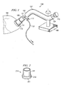
- FIGURE 1 illustrates an embodiment of a surgical device for positioning and stabilizing an organ.
- the apparatus comprises an arm 107, a base 103, and a suction element 109.
- the arm 107 has a distal end 102 and a proximal end 104.
- Arm 107 is coupled to a stabilizing base 103 to secure the arm 107.
- Arm 107 may be rotatable about the base 103 to provide further positioning for the surgeon.
- Stabilizing base 103 preferably comprises a clamp or fastener to secure apparatus to a surgical retractor or some other solid support.
- Distal end 102 of arm 107 is coupled to a suction element 109.
- Suction element 109 is generally hollow and has an opening at its distal end so that air may be sucked through the suction element 109 to create a vacuum or suction.
- the suction from suction element 109 serves to stabilize or hold an organ in place and also to facilitate connection of an implant to the organ.
- the distal or organ-contacting opening of the suction element 109 is adapted to conform to the surface of a specific organ.
- suction element 109 is adapted to fit over the apical portion of the left ventricle 180 of a heart.
- suction element 109 is coupled to the arm 107 in such a way as to extend longitudinally away from distal end of arm 107.
- suction element 109 may be attached or connected to flexible arm 107 by a hollow member 121.
- Hollow member 121 is preferably in fluid communication with suction element 109.
- a joint is disposed between hollow member 121 and distal end of arm 107 (not shown).
- hollow member 121 is connected to arm 107 by the joint.
- the joint provides further articulation for the arm 107 and allows easier positioning of the suction element over the organ. Any suitable joint may be utilized for this purpose including without limitation, hinges, ball joints, swivel joints, and the like.
- a vacuum line 131 is connected directly to suction element 109 to pull a vacuum within the element 109.
- vacuum line 131 is attached to hollow member 121.
- vacuum line 131 is run coaxially through arm 107 (not shown).
- the vacuum line 131 is typically connected to the vacuum connection available in any standard operating room.
- a valve 117 is disposed between the vacuum line and suction element. Valve 117 may be any suitable device used to regulate the vacuum.
- Suction element 109 is adapted to be releasably coupled to a surgical connector 114.
- the surgical connector 114 may be any connective device that is attached or sutured to an organ or a vessel (e.g. heart, liver, kidney, stomach, etc.) to form a connection between an artificial implant and an organ.
- suitable surgical connectors include without limitation, sleeves, grafts, cuffs, connectors, cannulas, and the like. Although such connectors are generally tubular in configuration, the surgical connector 114 may comprise any appropriate geometry suitable for surgical applications.
- the surgical connector 114 is an apical LVAD connector 214 as shown in Figure 2 .
- the apical LVAD connector is used to guide and connect the inflow conduit of an LVAD with the left ventricle of the heart.
- the apical LVAD connector 214 has a hollow body 241 having a heart-contacting end 251.
- Heart-contacting end 251 is circumferentially surrounded by a suture or sewing cuff 212. The surgeon sutures or stitches this cuff 212 to attach the connector 214 to the heart in water-tight fashion.
- the LVAD connector 214 is tubular in configuration.
- the LVAD connector may comprise any suitable geometry such as rectangular, hexagonal, oval, etc.
- suction element 109 is cylindrical or tubular in geometry.
- the suction element 109 may comprise any geometry such that it corresponds to a surgical connector.
- suction element 109 is adapted to have diameter such that it slidingly fits within the surgical connector 114.
- Surgical connector 114 is therefore held securely in place by the tight fit e.g. friction fit, between connector 114 and suction element 109.
- suction element 109 may have a greater diameter than the surgical connector 114 such that suction element can be placed over surgical connector 114.
- suction element 109 is adapted to releasably couple to existing surgical connectors in the marketplace.
- suction element 109 is configured or adapted to releasably couple to a surgical connector by any suitable connection means such as threaded or screw connections, snap-fit connections, bayonet connections, and the like.
- a surgical connector may be designed specifically for use with suction element 109.
- suction element 109 is detachably attached to hollow member 121.
- Suction element 109 may be coupled to hollow member 121 with any suitable coupling. The coupling preferably creates an air tight seal between suction element 109 and hollow member 121 to maintain the necessary suction.
- suitable connections include without limitation, threaded connections, bayonet connections, etc.
- suction element 109 is disposable and is replaced for each surgical procedure.
- both hollow member 121 and suction element are detachable from arm 107.
- Suction element 109 may be made of any suitable material.
- suction element 109 is made of a polymeric material.
- suitable polymeric materials include without limitation, polypropylene, polyethylene, silicone, polyurethane, polycarbonate, or combinations thereof.
- the material is preferably sterilizable or autoclavable. Such materials include without limitation, ceramics, glass, metal, or combinations thereof.
- Arm 107 is preferably flexible and is capable of being locked in various positions.
- arm 107 is segmented or articulated.
- arm 107 comprises a continuous tube or cylinder made from a polymeric material.
- By locking arm 107 into position the user is able to stabilize the organ in a desired position for attaching a surgical connection.
- arm 107 is locked into place by tension.
- arm 107 may be locked in place by any suitable means.
- arm 107 is held in place merely by the nature of the material.
- a non-resilient deformable material may be employed that is capable of holding its shape without tension or other means. Such materials may include without limitation, ductile metals, polymers, or combinations thereof.
- arm 107 is tubular in configuration. However, arm 107 may have different cross-sections such as rectangular, triangular, hexagonal, etc.
- the base 103 is clamped to a secured platform (i.e. a surgical retractor or the surgical table) to hold apparatus 100 in place.
- Vacuum is continuously pulled from suction element 109 through the vacuum line.
- Valve 117 may be used to temporarily halt vacuum through suction element 109.
- Surgical connector 114 is typically already inserted on to distal end of suction element 109 with the suture ring 112 oriented away from suction element opening.
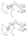
- the suction element 109 is then placed over the desired surgical site. Vacuum is re-applied and a portion of the organ surface is captured by suction element 109 via the force of the vacuum as shown in Figure 3a .
- the user may then move arm 107 into a desired position ( Figure 3b ).
- the organ 180 moves accordingly with the arm's movement.
- the arm 107 is locked either by turning knob 113 or merely left in place because of the material properties of the arm 107.
- the organ's position may be indefinitely maintained until user chooses to move arm 107.
- the disclosed apparatus 100 provide a means of positioning the organ, but it also stabilizes the organ surface during a surgical procedure.
- the ventricle is still beating at physiological pressure.
- the surface of the ventricle is in constant motion, providing an unstable surface for surgeons.
- the vacuum being pulled through suction element 109 immobilizes the undulating surface of the organ.
- surgical connector 114 is coupled to suction element 109, surgical connector 114 is also held in place against the surface of organ 180. As shown in Figure 3c , the surgeon is now able to attach or suture the stabilized surgical connector 114 on to the surface of organ 180 without concern that the surgical connector 114 will shift during attachment or suturing.
- a surgical connector e.g. an LVAD connector
- embodiments of the apparatus 100 provide a simple solution for stabilization and positioning of both the heart and the LVAD connector. It is envisioned that the above described methods and apparatus will not be limited to LVAD connectors and the heart, but may be used for other surgical connections and organs.
- the surgical connector 114 is attached to the organ surface via the connector's suture ring 112.
- the vacuum is disengaged and flexible arm 107 may be unfixed from its stationary position ( Figure 3d ).
- Suction element 109 is de-coupled from surgical connector 114 and organ 180, leaving surgical connector 114 attached to organ 180.
- the organ is a heart.
- other organs may be cored using embodiments of the disclosed system.
- the system allows a surgeon to form a hole in an organ such as without causing a significant amount of blood loss.
- the system ensures that all excised heart tissue is removed, leaving no remnants within the heart chamber.
- the system includes a coring tool 300, a balloon catheter, and a guide wire 340.
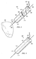
- FIGURE 4 illustrates an embodiment of a coring tool 300 that is used as part of the off-pump system.
- Coring tool 300 and balloon catheter both are longitudinally coaxial to guide wire.
- coring tool 300 has a hollow body 310.
- hollow body 310 has a coring portion 302, a vacuum chamber 304, and an inner elongate member 313.
- Coring portion 302 and vacuum chamber 304 of coring tool are preferably hollow.
- an outer guard wraps around the outer surface of coring tool 300 and slides along the longitudinal length of coring tool 300.
- coring portion 302 is forced into the desired portion of the organ to be cored. The cored tissue is pulled into vacuum chamber 304 by suction force. As will be described in more detail below, the opening created by the coring tool 300 may be blocked by the balloon portion of a balloon catheter.
- coring portion and vacuum chamber are integral to each other such that they form a single hollow body 402.
- coring tool need not be separable into two separate portions (i.e. coring portion 302 and vacuum chamber 304), but may comprise a uniform hollow body 402 with an open distal end 411 and a closed proximal end 406.
- Open distal end 417 has a cutting edge 411.
- Closed proximal end 406 has a vacuum connection 423, although vacuum connection 423 may also be located along hollow body 402.
- Hollow body 402 is preferably made of a translucent or transparent plastic to allow the user to visualize any excised tissue in hollow body lumen.
- hollow body 402 is made of metal or other suitable material. Examples of suitable materials include without limitation, polycarbonate, polystyrene, polyethylene, polypropylene, glass, stainless steel, or combinations thereof.
- coring portion 302 is tubular in configuration in order to cut a circular hole into an organ and is disposed distal to vacuum chamber 304.
- coring portion 302 may have any suitable cross-section for other purposes.
- Coring portion 302 has a cutting edge 311 at open distal end 317 of hollow body 310.
- Cutting edge 311 is preferably sharpened or tapered to easily bore through the heart tissue.
- proximal end of coring portion 302 is adapted to fit into vacuum chamber 304 or be attached to vacuum chamber 304.
- the outer surface of cutting edge 311 is beveled while the inner surface is straight or non-beveled as shown in Figure 4 .
- the inner surface of coring portion 302 may be flush with inner surface of vacuum chamber 304 to allow the excised tissue to pass through to vacuum chamber 304.
- coring portion 302 is made of metal such as surgical steel to easily penetrate into the heart tissue.
- metal such as surgical steel to easily penetrate into the heart tissue.
- any suitable materials may be used to construct coring portion.
- coring portion 302 may comprise a hard plastic or a polymeric material. It is envisioned that coring portion 302 may be re-usable and sterilizable. Alternatively, coring portion 302 may be disposable. In addition, coring portion 302 may be of any length in respect to vacuum portion.
- Vacuum chamber 304 of coring tool is also hollow and typically has the same cross-sectional geometry as coring portion 302.
- Proximal end of vacuum chamber 304 comprises closed proximal end 306 of hollow body 310 and is open at its distal end.
- a vacuum line 321 is attached to the closed end of vacuum chamber 304 via a vacuum connection 323.
- vacuum connection 323 is located along the outer surface of vacuum chamber 304.
- Vacuum connection 323 may comprise a valve (not shown) to adjust the vacuum being pulled in hollow body 310.
- a valve (not shown) is disposed between vacuum line 321 and closed end 306 of vacuum chamber 304 to regulate vacuum.
- a simple stopcock (not shown) may be employed to turn vacuum on or off.
- vacuum chamber 304 is adapted to receive coring portion 302 as seen in Figure 4 .
- Vacuum chamber 304 has a diameter that is greater than the diameter of the coring portion 302.
- coring portion 302 is insertable into the lumen of vacuum chamber 304 and is press-fit into place.
- coring portion 302 may be attached to vacuum chamber 304 by any suitable connection such as threaded connections, bayonet connections, snap-fit connections, and the like. Coupling between vacuum chamber 304 and coring portion 302 preferably forms an air tight seal capable of holding vacuum.
- vacuum chamber 304 has a diameter that is less than the diameter of the coring portion 302 such that vacuum chamber 304 is insertable into the lumen of coring portion 302.
- vacuum chamber 304 is transparent or translucent enabling a user to see the excised heart tissue as it is sucked into vacuum chamber 304.
- Vacuum chamber 304 is preferably made of a polymeric material. Any suitable polymeric material may be used that is capable of being sterilized and is biocompatible.
- vacuum chamber 304 is also disposable. Thus, in at least one embodiment, the vacuum chamber 304 and the coring portion 302 are both disposable.
- coring tool 300 further comprises an inner elongate member 413.
- the inner elongate member 413 is disposed coaxially within hollow body 410.
- the elongate member 313 is disposed coaxially within vacuum chamber 304 and coring portion 302. Proximal end of member 313 is attached to the proximal closed end 306 of hollow body 310 and extends longitudinally through the center of the hollow body lumen through the open distal end 317 of hollow body 310.
- inner elongate member 313 is hollow and is longitudinally coaxial with guide wire 340.
- inner elongate member 313 is extendible and retractable, thus allowing the distance of the member's distal tip 318 past cutting edge 311 to be adjusted according to the thickness of the organ tissue.
- inner elongate member 313 may be telescopic.
- elongate member 313 may extend through proximal closed end 306 of hollow body 310.
- Inner elongate member 313 serves several purposes. First, it guides coring tool 300 along guide wire 340 and maintains the coring tool's trajectory to the target heart tissue to be excised.
- the inner diameter of inner elongate member 313 is slightly greater than the guide wire diameter so that coring tool 300 precisely slides along guide wire to intended excision site.
- inner elongate member 313 also impales and secures the heart tissue to prevent any excised tissue from remaining in the heart chamber.
- Distal end 318 of elongate member 313 preferably comprises a "snout" or bullet shape. Alternatively, distal end 318 of elongate member 313 is a sharpened tip. However, distal end 318 may comprise any configuration suitable to easily penetrate the heart chamber.
- vacuum chamber has a handle (not shown) to assist the user in manipulating coring tool 300.
- the handle facilitates removal of the coring tool 300 along with the excised tissue from the organ.
- proximal end of elongate member 213 extends through closed end of hollow body 310 to form a handle.
- a handle may be attached to the outer surface of hollow body 310 or vacuum chamber 304.
- inner elongate member 313 extends through opening, past distal opening 317 of coring portion 302. This extension further allows elongate member 313 to act as a spacer between the cutting edge of coring tool 300 and balloon catheter.
- the spacer function prevents cutting edge from contacting the balloon catheter as coring tool 300 bores into the heart. As inner elongate member 313 penetrates through the heart wall, it pushes against the tip of balloon catheter and thus, forces balloon away from cutting edge.
- Inner elongate member 313 is preferably made of a semi-rigid material such as a polymer.
- a semi-rigid material such as a polymer.
- suitable materials include polyethylene, polypropylene, PET, or combinations thereof.
- inner elongate member may be made of metal.
- coring tool 300 comprises an outer guard (not shown).
- outer guard circumferentially surrounds coring tool 300. It is capable of sliding along the length of coring tool 300 over cutting edge even past the tip of inner elongate member 318.
- the purpose of the outer guard is to maintain a closed continuous passage as cored heart tissue is sucked into coring tool and coring tool is extracted from the heart.
- the outer guard prevents blood from escaping or spouting from the heart chamber in the time it takes balloon catheter to fill the newly formed hole in the ventricle.
- the coring device may comprise an inner hollow body (not shown) which is disposed coaxially within hollow body 402.
- inner hollow body is tubular in geometry.
- vacuum is only applied through inner hollow body.
- vacuum connection 423 would be coupled to the proximal end of inner hollow body to provide suction through inner hollow body.
- inner hollow body may be retractable through closed proximal end 406.
- inner elongate member 413 may be disposed coaxially within inner hollow body to provide guidance and further secure the excised tissue.
- the guide wire 340 is any suitable wire known to those of skill in the art. According to one embodiment, guide wire 340 acts a guide through the heart wall, the heart chamber, aortic arch, and the femoral artery. An advantage of using guide wire 340 is that it serves as a guiding track for coring tool 300 and balloon catheter. Therefore, guide wire 340 ensures that coring tool 300 and balloon catheter are properly aligned.
- Balloon catheter is adapted to be inserted into the heart chamber.
- Inflatable portion of balloon catheter is preferably inflatable to a diameter slightly greater than the diameter of coring portion 302. As will be described in more detail below, the larger diameter balloon plugs the hole created by the coring tool 300.
- Balloon catheter is made of any suitable biocompatible material.
- balloon catheter is replaced with some other catheter device which is capable of plugging a hole in the heart chamber. Further embodiments of the balloon catheter are described below.
- a guide wire 340 is attached to a needle.
- the surgeon prior to inserting a guide wire, the surgeon has attached an LVAD connector by techniques known to those of skill in the art or by the novel methods disclosed herein.
- the attached needle is then inserted into the target ventricle through the center of the LVAD connector. Because the heart is still pumping, the needle is automatically pumped through to the aorta.
- the needle and the guide wire navigate through the aortic arch and down the femoral artery. The user then extracts the needle from the femoral artery thereby forming a guide from the femoral artery all the way through the heart ventricle.
- a deflated balloon catheter is inserted through the femoral artery on to the guide wire.
- the guide wire serves as a track upon which the deflated balloon catheter rides as the user pushes the catheter up through the artery, through the aortic arch and back into the heart chamber.
- the balloon catheter is then inflated with contrast agent or any other suitable material.
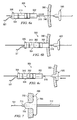
- coring tool 300 is then inserted on to guide wire 340 (see Figure 6a ).
- user may apply vacuum causing a pressure differential within the vacuum chamber 304 by turning a valve.
- User bores into heart chamber 390 with coring portion 302 until coring tool 300 penetrates into the interior of the heart chamber (see Figure 6b ).
- distal end 318 of elongate member 313 pierces heart chamber 390.
- the vacuum created by the pressure differential in the lumen of the coring tool 300 sucks the excised heart tissue into the lumen of the vacuum chamber 304.
- vacuum chamber 304 is transparent, surgeon can actually see when the excised heart tissue 392 enters the lumen of the vacuum chamber 304.
- the surgeon receives immediate visual confirmation that heart tissue has been completely resected.
- the inflated balloon catheter 500 plugs the tissue cavity formed by coring tool 300 by the outward pressure created by the beating heart when coring tool 300 is withdrawn from organ (see Figure 6c ).
- balloon catheter 500 acts as a plug to prevent the heart from spouting blood through the hole left by excision of heart tissue 392.
- balloon catheter 500 is a further measure to prevent excised heart tissue 392 from falling back into the ventricle.
- Elongate member 313 also serves to prevent heart tissue 392 from re-entering the heart chamber 390 as heart tissue 392 is securely impaled by elongate member 313.
- the surgeon can now insert an LVAD into the hole.
- the coring method above has been described with respect to the heart, it is envisioned that the disclosed coring system may be used with other organs or blood vessels requiring resection of a defined portion of tissue such as bladder, stomach, liver, etc.
- FIGURE 8 illustrates an embodiment of an automated surgical connector 800.
- the disclosed connector obviates the need for positioning and suturing a surgical connector to an organ such as the heart.
- suturing calls for repeated penetration of an organ.
- the surgical connector 800 instead is held in place by a novel press-fit mechanism involving the force of sealing members pressed against the organ wall.
- surgical connector 800 includes an inner body 810, an outer hollow body 830, a distal sealing member 840, and a proximal sealing member 850.
- inner body 810 is adapted to coaxially slide over a guide wire 890.
- inner body 810 has a distal portion 815, a proximal portion 811 and a medial portion 813.
- distal portion 815, proximal portion 811, and medial portion 813 form a continuous body.
- inner body 810 typically is circular in cross-section.
- inner body 810 may comprise any suitable cross-sectional geometry.
- inner body 810 may be hollow.
- inner body 810 may be solid as long as a passage is provided within inner body to allow threading of a guide wire 890.
- medial portion 813 has a greater diameter than distal portion 815 and proximal portion 811.
- the transition from medial portion 813 to distal portion 815 is preferably tapered or contoured so as to provide a transition zone for the distal sealing member 840.
- distal portion 815 has a blunt tip 816.
- Distal portion 815 may serve as a spacer between distal sealing member 840 and a balloon catheter in a guide wire coring system.
- blunt tip may be optimally configured so as to fit the outer surface of balloon catheter, further preventing any accidental puncture of the balloon.
- surgical connector 800 includes an intermediate sheath 820 as shown in Figure 9 .
- Figure 9 shows surgical connector 800 with only intermediate sheath 820, distal sealing member 840 and inner body 810.
- Intermediate sheath 820 is disposed around medial portion 813 of inner body 810 in between outer hollow body 830 and inner body 810.
- intermediate sheath 820 is made of any suitable metal.
- intermediate sheath 820 may also be made of plastic.
- intermediate sheath 820 is typically slidably disposed around medial portion 813 of inner body 810.
- intermediate sheath 820 has a diameter that in only slightly greater than the diameter of medial portion 813.
- Intermediate sheath 820 serves to maintain distal sealing member 840 in its expanded position as will be described in more detail below.
- distal sealing member 840 comprises a support portion 842 and a sealing portion 846. Furthermore, the support portion 842 and sealing portion 846 together comprise a plurality of ribs 841. Each rib 841 has an axial portion 843 and a radial portion 844. Thus, axial portion 843 of each rib forms the framework or skeleton for support portion 842 while radial portion 844 of each rib 841 forms the framework for sealing portion 846. Axial portion 843 of each rib is preferably aligned along the longitudinal axis of inner body 810. In one embodiment, axial portion 843 of each rib 841 is tapered toward the distal end 847 of axial portion 843. The tapered axial portion 843 allows the distal sealing member 840 to expand or spread radially outward.
- Radial portion 844 forms an angle with axial portion 843 and extends radially outward from axial portion 843. Radial portion 844 may form any suitable angle with axial portion 843. As with axial portion 843, radial portion 844 of each rib 841 may comprises a taper so as to accommodate expansion of distal sealing member 840. As shown in Figure 9 , radial portion 844 tapers from outer tip 845 to intersection of radial portion 844 with axial portion 843. Furthermore, in some embodiments, outer tip 845 of radial portion 844 is bent at an angle. The bent outer tip 845 facilitates compression of distal sealing member by outer hollow body 830. In yet other embodiments, outer tip 845 of radial portion 844 may overlap with the outer tips 845 of other ribs (not shown). This overlapping may allow for more compact compression of distal sealing member 840 in its compressed position.
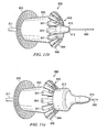
- Distal sealing member 840 has a collapsed position and an expanded position as depicted in Figure 10.
- Figure 10 illustrates the transition from distal sealing member's 840 compressed position in Figure 10A to its expanded position in Figure 10C .
- ribs 841 of distal sealing member 840 are contracted over distal portion of inner body 810.
- the taper in axial portion 843 and radial portion 844 of ribs 841 allow the ribs 841 to contract against each other.
- axial portion 843 and radial portion 844 may be configured to overlap one another for further compression or contraction.
- other geometries may be incorporated to optimize contraction of distal sealing member 840.
- each axial portion 843 may comprise an angled portion (not shown).
- the axial portions of ribs 841 when contracted, may form a frustroconical support portion 842 surrounding distal portion 815 of inner body 810.
- support portion 842 may comprise other configurations in order to conform to inner body 810 when compressed.
- proximal end 848 of each axial portion 843 may be in contact with medial portion 813 of inner body 810 to begin the expansion of distal sealing member 840.
- medial portion 813 spreads or forces axial portions 841 apart as illustrated in Figure 10B .
- ribs 841 are completely spread or expanded into the expanded position of distal sealing member 840 in Figure 10C .
- ribs 841 are planar in geometry. However, it is contemplated that ribs 841 may be of any geometry allows the ribs 841 to expand or collapse. For example, ribs 841 may also be cylindrical in cross-section e.g. wires. In preferred embodiments, ribs 841 are made of a non-thrombogenic metal. Generally, the metal is a resilient metal so as to impart spring-like properties to the ribs. Examples of suitable metals include without limitation, nitinol, copper, stainless steel, titanium, zinc, nickel, or combinations thereof. Distal sealing member 840 is also covered with a non-thrombogenic mesh or fabric.
- the mesh or fabric ensures the distal sealing member 840 forms a liquid tight seal with proximal sealing member.
- the material may be a polymeric fabric made from polytetrafluorethylene (PTFE), polypropylene, polyurethane, nylon, or combinations thereof.
- PTFE polytetrafluorethylene
- any suitable non-thrombogenic, biocompatible materials known to those of ordinary skill in the art may be used.
- An advantage of the disclosed connector over prior devices is that it does not have an inner cannula. Blood flowing from ventricle through connector will contact only the continuous surface of distal sealing member 840 and inner surface of intermediate sheath 820. These features lessen the chance of clots or thrombi forming in the heart.
- Surgical connector 800 also comprises an outer hollow body 830.
- inner body 810 is disposed coaxially within outer hollow body 830.
- outer hollow body 830 has a diameter slightly greater than medial portion 813 of inner body 810.
- Outer hollow body 830 is disposed around intermediate sheath 820 and medial portion 813 of inner body 810.
- outer hollow body 830 slides along medial portion of inner body.
- Outer hollow body 830 may be made of any suitable material such as plastic or metal.
- surgical connector comprises a proximal sealing member 850.
- proximal sealing member 850 may also be comprised of a plurality of ribs (not shown) covered with a mesh or fabric as shown in Figure 8 .
- proximal sealing member 850 comprises a solid and continuous piece of metal or plastic (not shown).
- proximal sealing member 850 is angled or contoured distally toward the distal end of inner body.
- proximal sealing member is movably disposed around outer hollow body 830.
- proximal sealing member is capable of being locked into position along outer hollow body 830. Any suitable mechanisms may accomplish this such as a threaded connection or ratchet mechanism between outer hollow body 830 and proximal sealing member. The mechanism allows the proximal sealing member 850 to move in a distal direction, but prevents the proximal sealing member from moving back in a proximal direction. In this way, organ or tissue is securely clamped between proximal sealing member and distal sealing member 840 to form a liquid tight or press-fit seal.
- the described surgical connector 800 is used in conjunction with the coring system disclosed above.
- a guide-wire coring system of which embodiments are described above, is used to create a hole in the organ. After the coring procedure, the balloon catheter remains in the newly created hole to prevent blood loss.
- other coring procedures may be utilized in conjunction with embodiments of the surgical connector 800.
- Distal end 816 of inner body 810 is preferably blunt to prevent puncture of balloon catheter.
- blunt tip 816 of distal end the surgeon rapidly pushes balloon catheter back into the organ while inserting medial portion 813 of inner body 810 into the void or hole left by balloon catheter.
- medial portion 816 has a diameter substantially equal to the diameter of the hole in the organ, insertion of medial portion prevents any loss of fluids from organ.
- Medial portion 813 of inner body 810 is inserted until proximal sealing member 850 contacts the outer surface of organ.
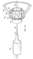
- Distal sealing member 840 is held in its compressed position by outer hollow body 830 as shown in Figure 11A . Once medial portion 813 has been inserted, the surgeon pulls back outer hollow body 830 allowing the ribs 841 of distal sealing member 840 to spring radially outward as seen in Figure 11B .
- inner body 810 is further pushed distally into organ 880. See Figure 10C & Figure 8 .
- medial portion 813 of inner body 810 is pushed inward, axial portions 843 of each rib 841 engage intermediate sheath 820 surrounding medial portion 813.
- Ribs 841 are further displaced radially outward until distal sealing member 840 reaches its fully expanded position.
- intermediate sheath 820 slides underneath axial portions of ribs to lock distal sealing member 840 into its expanded position as shown in Figure 9 . That is, intermediate sheath 820 prevents distal sealing member 840 from reverting to its compressed position and maintains distal sealing member 840 in its fully expanded position.
- Intermediate sheath 820 may comprise a stop or tab located at its proximal end to indicate to surgeon that distal sealing member 840 is fully expanded and locked into position.
- distal sealing member 840 Once distal sealing member 840 is locked into position, surgeon may adjust or tighten proximal sealing member 850 against outer surface of organ to secure a liquid tight seal.
- the tightening may be accomplished by whatever mechanism is incorporated by the device such as a ratchet mechanism or a screw connection (not shown).
- organ wall will be securely clamped between inner and proximal sealing member 830, 850 to form a press-fit type connection.
- the disclosed surgical connector 800 does not need sutures to be secured to the organ 880.
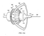
- the surgeon may then pull inner body 810 from intermediate sheath 820 and outer hollow body 830 leaving a secured connector or conduit for attachment of a surgical device as seen in Figure 12B .
- the surgical device is an LVAD, although any suitable surgical device may be attached to surgical connector 800.
- the balloon catheter once again serves as a plug to prevent blood loss from the organ.
- the coring system described above is preferably used in conjunction with a balloon-type catheter specifically designed for blocking a cavity in the ventricle.
- the balloon catheter 700 is coaxial with guide wire 701.
- the inflatable balloon portion of catheter 700 may comprise any shape that is suitable for blocking a hole in the ventricle.
- balloon has a frusto-conical shape when inflated.
- balloon comprises a seal or cuff portion 403 continuous with a distal projection 705 to form a nipple shaped balloon ( Figure 7 ).
- the distal projection 703 is ideally approximately the same diameter as the cored hole while seal portion 705 has a greater diameter than distal portion 705 to form a seal within the ventricle 750.
- Seal portion may have a convex curvature which closely resembles the curvature of the ventricle.
- Distal tip of distal projection 705 is preferably bullet shaped to allow catheter to easily slip through and plug cored hole.
- the distal tip 713 of catheter body 717 is optimally spaced to prevent coring tool from puncturing balloon.
- catheter comprises a mechanically expandable seal (not shown).
- a mechanically expandable seal (not shown).
- the advantage of this embodiment is that there would be no danger of puncturing an inflated balloon. It is envisioned that the expandable and collapsible mechanical seal would operate much like an umbrella. The mechanical seal would operate similarly to the expandable sealing member described above.
- mechanical seal comprises a collapsible skeleton or frame covered by a non-thrombogenic material. The mechanical seal preferably has a curved aspect to better fit the interior of the ventricle.
- An additional embodiment of balloon catheter comprises a low-profile proximal valve (not shown).
- proximal valve has the same diameter as the catheter body.
- Proximal valve is generally a one way valve. That is, proximal valve allows the balloon catheter to be filled with liquid or gas, but maintains pressure within the balloon portion after balloon portion has been inflated. Any suitable valve known to those of skill in the art may be used.
- balloon catheter further comprises a proximal catheter portion which is coupled to the proximal valve after balloon inflation such that distal catheter portion and proximal catheter portion form a continuous catheter body.
- Catheter body preferably has a small diameter, ranging from about 0.01 mm to about 10 mm. It is envisioned that catheter body may act as a guide wire for various surgical devices including without limitation, the coring tool 300 or surgical connector 800.
- balloon catheter 700 and coring tool 300 may be used as part of a surgical coring system without the need for an additional guide wire.
- balloon catheter does not require a guide wire. Instead, the distal tip of balloon catheter is inserted at the target area of an organ. An incision may optionally be made at the target area to facilitate insertion of balloon catheter.
- Balloon catheter is inserted into the organ and then inflated by injecting either a fluid or a gas into the balloon. Balloon portion may be inflated by any suitable device such as a pump, injection port, syringe, etc. attached to the proximal valve of balloon catheter. Once balloon portion is inflated, the injection device is removed from proximal valve. Because of the one-way nature of the valve, the balloon portion remains inflated even after the injection device is removed. The proximal portion is then attached to the distal portion through a suitable connection such as a threaded connection forming the continuous catheter body.
- kits for off-pump connection of an artificial device may comprise the disclosed surgical connector, an embodiment of a balloon catheter as described above, a guide wire, and the disclosed coring tool.
- the kit may comprise any combination or number of the surgical devices disclosed herein.
- any of the methods and apparatuses described herein are not limited to off-pump surgery, but may be used in conjunction with any surgical procedure whether it be on-pump or off-pump.
Claims (15)
- Dispositif chirurgical, comprenant :un connecteur chirurgical (114, 214), adapté pour être fixé ou attaché par suture sur un organe (180) ou un vaisseau ;un élément d'aspiration (109), adapté pour être accouplé de manière amovible au connecteur chirurgical (114, 214), dans lequel ledit élément d'aspiration (109) comporte une ouverture pour positionner et stabiliser le connecteur chirurgical (114, 214) contre la surface de l'organe (180) ou du vaisseau par aspiration ; etun bras flexible (107), connecté audit élément d'aspiration (109), ledit bras flexible (107) pouvant être fixé dans une position stationnaire pour retenir le connecteur chirurgical (114, 214) et l'organe (180) ou le vaisseau dans leur position au cours de la fixation ou de la suture dudit connecteur chirurgical stabilisé (114, 214) sur la surface dudit organe (180) ou dudit vaisseau ;dans lequel ledit connecteur chirurgical (114, 214) est adapté pour rester fixé ou attaché par suture sur ledit organe (180) ou ledit vaisseau après son désaccouplement dudit élément d'aspiration (109).
- Dispositif chirurgical selon la revendication 1, dans lequel ledit élément d'aspiration (109) est adapté pour être accouplé de manière amovible audit connecteur chirurgical (114, 214) par une connexion sélectionnée dans le groupe constitué par une connexion filetée, une connexion à baïonnette, une connexion par encliquetage ou un ajustement serré.
- Dispositif chirurgical selon la revendication 1, dans lequel ledit élément d'aspiration (109) est adapté pour être ajusté de manière coulissante dans ledit connecteur chirurgical (114 , 214) ou autour de celui-ci.
- Dispositif chirurgical selon la revendication 1, dans lequel ledit connecteur chirurgical (114, 214) est un connecteur d'un dispositif d'assistance ventriculaire.
- Dispositif chirurgical selon la revendication 1, dans lequel ledit bras flexible (107) est connecté audit élément d'aspiration (109) par un élément creux (121), ledit élément creux (121) étant en communication de fluide avec ledit élément d'aspiration (109).
- Dispositif chirurgical selon la revendication 5, comprenant en outre une ligne à vide (131) fixée sur ledit élément creux (121).
- Dispositif chirurgical selon la revendication 1, dans lequel ledit bras flexible (107) est creux.
- Dispositif chirurgical selon la revendication 7, dans lequel une ligne à vide (131) est fixée sur l'extrémité proximale (104) dudit bras flexible (107), de sorte que le vide est attiré à partir de l'élément d'aspiration (109) à travers ledit bras flexible (107).
- Dispositif chirurgical selon la revendication 1, dans lequel ledit élément d'aspiration (109) est fixé de manière détachable sur ledit bras flexible (107).
- Dispositif chirurgical selon la revendication 5, dans lequel ledit élément creux (121) est fixé sur ledit bras flexible (107) par un joint sélectionné dans le groupe constitué par une charnière, d'un joint pivotant et d'un joint à rotule.
- Dispositif chirurgical selon la revendication 1, dans lequel ledit élément d'aspiration (109) est tubulaire.
- Dispositif chirurgical selon la revendication 1, dans lequel ledit bras flexible (107) comprend un matériau non élastique déformable.
- Dispositif chirurgical selon la revendication 1, dans lequel ledit élément d'aspiration (109) comprend un matériau polymère.
- Dispositif chirurgical selon la revendication 1, dans lequel ledit connecteur chirurgical (114, 214) est accouplé de manière coaxiale audit élément d'aspiration (109).
- Dispositif chirurgical selon la revendication 1, dans lequel ledit connecteur chirurgical (114, 214) comprend un corps creux (241) comportant une extrémité en contact avec l'organe (251), ladite extrémité en contact avec l'organe (251) étant entourée par un manchon (212).
Applications Claiming Priority (5)
| Application Number | Priority Date | Filing Date | Title |
|---|---|---|---|
| US80667006P | 2006-07-06 | 2006-07-06 | |
| US11/770,272 US7744527B2 (en) | 2006-07-06 | 2007-06-28 | Surgical coring system |
| US11/770,254 US7717844B2 (en) | 2006-07-06 | 2007-06-28 | Method and apparatus for stabilization and positioning during surgery |
| US11/770,288 US7931581B2 (en) | 2006-07-06 | 2007-06-28 | Automated surgical connector |
| PCT/US2007/072759 WO2008005990A2 (fr) | 2006-07-06 | 2007-07-03 | Outils chirurgicaux pour implantation de dispositifs d'assistance ventriculaire gauche |
Publications (3)
| Publication Number | Publication Date |
|---|---|
| EP2040639A2 EP2040639A2 (fr) | 2009-04-01 |
| EP2040639A4 EP2040639A4 (fr) | 2011-07-27 |
| EP2040639B1 true EP2040639B1 (fr) | 2014-02-26 |
Family
ID=38920010
Family Applications (1)
| Application Number | Title | Priority Date | Filing Date |
|---|---|---|---|
| EP07799289.9A Not-in-force EP2040639B1 (fr) | 2006-07-06 | 2007-07-03 | Outils chirurgicaux pour implantation de dispositifs d'assistance ventriculaire gauche |
Country Status (6)
| Country | Link |
|---|---|
| US (3) | US7744527B2 (fr) |
| EP (1) | EP2040639B1 (fr) |
| JP (1) | JP5596974B2 (fr) |
| AU (1) | AU2007269104B2 (fr) |
| CA (1) | CA2657008A1 (fr) |
| WO (1) | WO2008005990A2 (fr) |
Cited By (9)
| Publication number | Priority date | Publication date | Assignee | Title |
|---|---|---|---|---|
| US10881770B2 (en) | 2018-01-10 | 2021-01-05 | Magenta Medical Ltd. | Impeller for blood pump |
| US11191944B2 (en) | 2019-01-24 | 2021-12-07 | Magenta Medical Ltd. | Distal tip element for a ventricular assist device |
| US11260212B2 (en) | 2016-10-25 | 2022-03-01 | Magenta Medical Ltd. | Ventricular assist device |
| US11291824B2 (en) | 2015-05-18 | 2022-04-05 | Magenta Medical Ltd. | Blood pump |
| US11291826B2 (en) | 2018-01-10 | 2022-04-05 | Magenta Medical Ltd. | Axially-elongatable frame and impeller |
| US11298521B2 (en) | 2013-03-13 | 2022-04-12 | Magenta Medical Ltd. | Methods of manufacturing an impeller |
| US11484701B2 (en) | 2013-03-13 | 2022-11-01 | Magenta Medical Ltd. | Vena-caval occlusion element |
| US11648392B2 (en) | 2016-11-23 | 2023-05-16 | Magenta Medical Ltd. | Blood pumps |
| US11839540B2 (en) | 2012-06-06 | 2023-12-12 | Magenta Medical Ltd | Vena-caval apparatus and methods |
Families Citing this family (51)
| Publication number | Priority date | Publication date | Assignee | Title |
|---|---|---|---|---|
| US9138228B2 (en) | 2004-08-11 | 2015-09-22 | Emory University | Vascular conduit device and system for implanting |
| US7744527B2 (en) * | 2006-07-06 | 2010-06-29 | Apaxis Medical, Inc. | Surgical coring system |
| WO2008073852A2 (fr) * | 2006-12-08 | 2008-06-19 | Onset Medical Corporation | Gaine d'accès médicale extensible |
| US7846123B2 (en) | 2007-04-24 | 2010-12-07 | Emory University | Conduit device and system for implanting a conduit device in a tissue wall |
| US20090326518A1 (en) * | 2008-02-14 | 2009-12-31 | Rabin Barry H | Devices and methods for manipulating tissue |
| JP5651021B2 (ja) * | 2008-03-06 | 2015-01-07 | クック メディカル テクノロジーズ エルエルシーCook Medical Technologies Llc | 体内の穴へアクセスするための医療装置 |
| US20100312054A1 (en) * | 2008-05-06 | 2010-12-09 | N.M.B. Medical Applications Ltd. | Prostatic tissue removal and/or prostatic capsulotomy for treatment of conditions |
| US20100160725A1 (en) * | 2008-12-19 | 2010-06-24 | Andy Christopher Kiser | Methods and Devices for Endoscopic Access to the Heart |
| EP2453814A2 (fr) * | 2009-07-14 | 2012-05-23 | Apaxis Medical, Inc. | Cathéter à ballonnet destiné à être utilisé avec un système d'exérèse chirurgicale |
| US20110118833A1 (en) * | 2009-11-15 | 2011-05-19 | Thoratec Corporation | Attachment device and method |
| US20110118829A1 (en) * | 2009-11-15 | 2011-05-19 | Thoratec Corporation | Attachment device and method |
| US9682180B2 (en) * | 2009-11-15 | 2017-06-20 | Thoratec Corporation | Attachment system, device and method |
| US8152845B2 (en) * | 2009-12-30 | 2012-04-10 | Thoratec Corporation | Blood pump system with mounting cuff |
| JP6130302B2 (ja) | 2011-01-28 | 2017-05-17 | アピカ カーディオヴァスキュラー リミテッド | 組織壁の刺し傷を封止するシステム |
| CA2826413A1 (fr) | 2011-02-01 | 2012-08-09 | Georgia Tech Research Corporation | Systemes d'implantation et d'utilisation d'un conduit dans une paroi tissulaire |
| EP2677943B1 (fr) | 2011-02-25 | 2016-08-31 | Thoratec Corporation | Système d'accouplement de connexion d'un conduit sur du tissu biologique |
| EP2995327A1 (fr) | 2011-03-02 | 2016-03-16 | Thoratec Corporation | Manchon ventriculaire |
| WO2012158968A2 (fr) | 2011-05-18 | 2012-11-22 | Thoratec Corporation | Protecteur d'aiguille, ensemble et méthode d'implantation d'un système d'assistance cardiaque |
| US9044236B2 (en) | 2011-05-18 | 2015-06-02 | Thoratec Corporation | Coring knife |
| US9237933B2 (en) * | 2011-10-21 | 2016-01-19 | Specialty Surgical Instrumentation Inc. | Universal arm system |
| KR20140099535A (ko) | 2011-12-07 | 2014-08-12 | 월드 하트 코포레이션 | 캐뉼러 링, 관련 시스템 및 방법 |
| US8579790B2 (en) | 2012-01-05 | 2013-11-12 | Thoratec Corporation | Apical ring for ventricular assist device |
| WO2013130658A1 (fr) * | 2012-02-27 | 2013-09-06 | Kamler Jan | Appareil de bandage et procédé d'utilisation |
| US9199019B2 (en) | 2012-08-31 | 2015-12-01 | Thoratec Corporation | Ventricular cuff |
| US9981076B2 (en) | 2012-03-02 | 2018-05-29 | Tc1 Llc | Ventricular cuff |
| WO2013162741A1 (fr) | 2012-04-23 | 2013-10-31 | Thoratec Corporation | Dispositif de pose et procédé de mise en place d'agrafes anastomatiques |
| JP2014004016A (ja) * | 2012-06-21 | 2014-01-16 | Olympus Corp | アクセスポート |
| EP2895083B1 (fr) | 2012-09-14 | 2018-07-04 | Alpine Medical Devices, LLC | Ligateur |
| WO2014062827A1 (fr) | 2012-10-16 | 2014-04-24 | Spence Paul A | Dispositifs, systèmes et procédés pour faciliter l'écoulement du cœur à une pompe à sang |
| EP2948104B1 (fr) | 2013-01-25 | 2019-07-24 | Apica Cardiovascular Limited | Systèmes pour accès percutané, stabilisation et fermeture d'organes |
| JP6302992B2 (ja) | 2013-03-15 | 2018-03-28 | エーピーケー アドバンスド メディカル テクノロジーズ,インコーポレイテッド | 組織壁に移植するためのコネクタ |
| WO2015109328A2 (fr) * | 2014-01-17 | 2015-07-23 | Correx, Inc. | Appareil et procédé permettant de former un trou dans un organe creux, de raccorder un conduit à cet organe creux et à raccorder un dispositif d'assistance ventriculaire gauche (lvad) audit organe creux |
| GB2527075A (en) * | 2014-03-17 | 2015-12-16 | Daassist As | Percutaneous system, devices and methods |
| EP3212250A4 (fr) | 2014-10-31 | 2018-07-11 | Thoratec Corporation | Connecteurs apicaux et instruments pour utilisation dans une paroi cardiaque |
| WO2017120449A2 (fr) | 2016-01-06 | 2017-07-13 | Bivacor Inc. | Pompe cardiaque |
| US10159772B2 (en) | 2016-03-30 | 2018-12-25 | Heartware, Inc. | Flanged heart tissue blocker |
| US10894116B2 (en) | 2016-08-22 | 2021-01-19 | Tc1 Llc | Heart pump cuff |
| WO2018039042A1 (fr) * | 2016-08-24 | 2018-03-01 | Terumo Cardiovascular Systems Corporation | Aide à la suture pour greffe de grand vaisseau |
| US11235137B2 (en) | 2017-02-24 | 2022-02-01 | Tc1 Llc | Minimally invasive methods and devices for ventricular assist device implantation |
| CN110709114B (zh) | 2017-04-05 | 2023-10-31 | 毕瓦克公司 | 心脏泵驱动器和轴承 |
| EP4233989A3 (fr) | 2017-06-07 | 2023-10-11 | Shifamed Holdings, LLC | Dispositifs de déplacement de fluide intravasculaire, systèmes et procédés d'utilisation |
| US10335527B2 (en) | 2017-11-08 | 2019-07-02 | The Regents Of The University Of Colorado, A Body Corporate | Ventricular assist assembly, system, and method |
| JP7319266B2 (ja) | 2017-11-13 | 2023-08-01 | シファメド・ホールディングス・エルエルシー | 血管内流体移動デバイス、システム、および使用方法 |
| CN112004563A (zh) | 2018-02-01 | 2020-11-27 | 施菲姆德控股有限责任公司 | 血管内血泵以及使用和制造方法 |
| US10881430B2 (en) | 2018-04-11 | 2021-01-05 | Vadovations, Inc. | Tissue interface apparatus, systems, and methods |
| FR3081333B1 (fr) * | 2018-05-22 | 2020-06-05 | Fineheart | Dispositif d'ancrage d'une pompe cardiaque |
| USD1024310S1 (en) | 2019-03-28 | 2024-04-23 | Bateman Bottle, Llc | Implant removal device |
| JP2022540616A (ja) | 2019-07-12 | 2022-09-16 | シファメド・ホールディングス・エルエルシー | 血管内血液ポンプならびに製造および使用の方法 |
| WO2021016372A1 (fr) | 2019-07-22 | 2021-01-28 | Shifamed Holdings, Llc | Pompes à sang intravasculaires à entretoises et procédés d'utilisation et de fabrication |
| EP4034192A4 (fr) | 2019-09-25 | 2023-11-29 | Shifamed Holdings, LLC | Dispositifs et systèmes de pompes à sang intravasculaires et leurs procédés d'utilisation et de commande |
| TR201923195A2 (tr) * | 2019-12-31 | 2021-07-26 | Ahmet Elibol | Ventri̇küler destek ci̇hazlarinin vakum destekli̇ di̇ki̇şsi̇z gi̇ri̇ş kanül i̇mplantasyonu |
Family Cites Families (29)
| Publication number | Priority date | Publication date | Assignee | Title |
|---|---|---|---|---|
| SE459635B (sv) * | 1987-11-19 | 1989-07-24 | Radiplast Ab | Drivaggregat foer en anordning foer vaevnadsprovtagning |
| FR2711504B1 (fr) * | 1993-10-26 | 1996-01-19 | Ethnor | Instrument chirurgical pour le traitement d'une collection liquidienne, en particulier pour la stérilisation et l'aspiration d'un kyste hydatique. |
| US5649547A (en) * | 1994-03-24 | 1997-07-22 | Biopsys Medical, Inc. | Methods and devices for automated biopsy and collection of soft tissue |
| WO1997013471A1 (fr) * | 1995-10-13 | 1997-04-17 | Transvascular, Inc. | Dispositif, systeme et procede permettant une intervention interstitielle transvasculaire |
| EP0954248B1 (fr) * | 1995-10-13 | 2004-09-15 | Transvascular, Inc. | Appareils pour le pontage d'obstructions arterielles, et/ou servant a effectuer d'autres interventions transvasculaires |
| US5782823A (en) * | 1996-04-05 | 1998-07-21 | Eclipse Surgical Technologies, Inc. | Laser device for transmyocardial revascularization procedures including means for enabling a formation of a pilot hole in the epicardium |
| US6019722A (en) * | 1997-09-17 | 2000-02-01 | Guidant Corporation | Device to permit offpump beating heart coronary bypass surgery |
| US6390976B1 (en) * | 1997-09-17 | 2002-05-21 | Origin Medsystems, Inc. | System to permit offpump beating heart coronary bypass surgery |
| US6152937A (en) * | 1998-11-06 | 2000-11-28 | St. Jude Medical Cardiovascular Group, Inc. | Medical graft connector and methods of making and installing same |
| US6319231B1 (en) * | 1999-02-12 | 2001-11-20 | Abiomed, Inc. | Medical connector |
| US6682505B2 (en) * | 1999-03-12 | 2004-01-27 | Arteria Medical Science, Inc. | Catheter for removing emboli from saphenous vein grafts and native coronary arteries |
| US6860892B1 (en) * | 1999-05-28 | 2005-03-01 | General Surgical Innovations, Inc. | Specially shaped balloon device for use in surgery and method of use |
| US6610071B1 (en) * | 1999-07-26 | 2003-08-26 | Beth Israel Deaconess Medical Center | Suture system |
| US6652485B1 (en) * | 2000-05-31 | 2003-11-25 | Advanced Cardiovascular Systems, Inc. | Balloon shoulder designs |
| WO2002001999A2 (fr) * | 2000-06-30 | 2002-01-10 | Viacor, Incorporated | Procede et appareil permettant d'effectuer une intervention sur une valvule cardiaque |
| US6676597B2 (en) * | 2001-01-13 | 2004-01-13 | Medtronic, Inc. | Method and device for organ positioning |
| CA2437824C (fr) * | 2001-02-05 | 2008-09-23 | Viacor, Inc. | Appareil et procede permettant de diminuer la regurgitation mitrale |
| US20030093105A1 (en) * | 2001-07-13 | 2003-05-15 | Scimed Life Systems, Inc. | Guide catheter for introduction into the subarachnoid space and methods of use thereof |
| EP1467658A1 (fr) * | 2002-01-23 | 2004-10-20 | Iotek, Inc. | Dispositifs pour maintenir un organe corporel |
| US6866628B2 (en) * | 2002-04-11 | 2005-03-15 | Medtronic, Inc. | Apparatus for temporarily engaging body tissue |
| US6758809B2 (en) * | 2002-06-06 | 2004-07-06 | Medtronic, Inc. | Surgical tool for engagement of body tissue |
| US7494460B2 (en) * | 2002-08-21 | 2009-02-24 | Medtronic, Inc. | Methods and apparatus providing suction-assisted tissue engagement through a minimally invasive incision |
| EP1551315A2 (fr) * | 2002-10-04 | 2005-07-13 | St. Jude Medical ATG, Inc. | Connecteurs externes auto-dilatables permettant de creer des anastomoses sur des vaisseaux de faible diametre et procedes d'utilisation |
| US7048681B2 (en) * | 2003-03-28 | 2006-05-23 | Terumo Corporation | Method and apparatus for adjusting a length of the inflow conduit on a ventricular assist device |
| US8308682B2 (en) * | 2003-07-18 | 2012-11-13 | Broncus Medical Inc. | Devices for maintaining patency of surgically created channels in tissue |
| US7399272B2 (en) * | 2004-03-24 | 2008-07-15 | Medtronic, Inc. | Methods and apparatus providing suction-assisted tissue engagement |
| US7708721B2 (en) * | 2004-04-05 | 2010-05-04 | University Of Medicine & Dentistry Of New Jersey | Vascular access needle |
| US20060200041A1 (en) * | 2005-03-04 | 2006-09-07 | Ethicon Endo-Surgery, Inc. | Biopsy device incorporating an adjustable probe sleeve |
| US7744527B2 (en) * | 2006-07-06 | 2010-06-29 | Apaxis Medical, Inc. | Surgical coring system |
-
2007
- 2007-06-28 US US11/770,272 patent/US7744527B2/en not_active Expired - Fee Related
- 2007-06-28 US US11/770,254 patent/US7717844B2/en not_active Expired - Fee Related
- 2007-06-28 US US11/770,288 patent/US7931581B2/en not_active Expired - Fee Related
- 2007-07-03 CA CA002657008A patent/CA2657008A1/fr not_active Abandoned
- 2007-07-03 EP EP07799289.9A patent/EP2040639B1/fr not_active Not-in-force
- 2007-07-03 WO PCT/US2007/072759 patent/WO2008005990A2/fr active Application Filing
- 2007-07-03 JP JP2009518616A patent/JP5596974B2/ja not_active Expired - Fee Related
- 2007-07-03 AU AU2007269104A patent/AU2007269104B2/en not_active Ceased
Cited By (34)
| Publication number | Priority date | Publication date | Assignee | Title |
|---|---|---|---|---|
| US11839540B2 (en) | 2012-06-06 | 2023-12-12 | Magenta Medical Ltd | Vena-caval apparatus and methods |
| US11883274B2 (en) | 2013-03-13 | 2024-01-30 | Magenta Medical Ltd. | Vena-caval blood pump |
| US11850415B2 (en) | 2013-03-13 | 2023-12-26 | Magenta Medical Ltd. | Blood pump |
| US11648391B2 (en) | 2013-03-13 | 2023-05-16 | Magenta Medical Ltd. | Blood pump |
| US11484701B2 (en) | 2013-03-13 | 2022-11-01 | Magenta Medical Ltd. | Vena-caval occlusion element |
| US11298520B2 (en) | 2013-03-13 | 2022-04-12 | Magenta Medical Ltd. | Impeller for use with axial shaft |
| US11298521B2 (en) | 2013-03-13 | 2022-04-12 | Magenta Medical Ltd. | Methods of manufacturing an impeller |
| US11291824B2 (en) | 2015-05-18 | 2022-04-05 | Magenta Medical Ltd. | Blood pump |
| US11648387B2 (en) | 2015-05-18 | 2023-05-16 | Magenta Medical Ltd. | Blood pump |
| US11291825B2 (en) | 2016-10-25 | 2022-04-05 | Magenta Medical Ltd. | Ventricular assist device |
| US11260212B2 (en) | 2016-10-25 | 2022-03-01 | Magenta Medical Ltd. | Ventricular assist device |
| US11839754B2 (en) | 2016-10-25 | 2023-12-12 | Magenta Medical Ltd | Ventricular assist device |
| US11648392B2 (en) | 2016-11-23 | 2023-05-16 | Magenta Medical Ltd. | Blood pumps |
| US11690521B2 (en) | 2018-01-10 | 2023-07-04 | Magenta Medical Ltd. | Impeller for blood pump |
| US10905808B2 (en) | 2018-01-10 | 2021-02-02 | Magenta Medical Ltd. | Drive cable for use with a blood pump |
| US11950889B2 (en) | 2018-01-10 | 2024-04-09 | Magenta Medical Ltd. | Ventricular assist device |
| US11944413B2 (en) | 2018-01-10 | 2024-04-02 | Magenta Medical Ltd. | Ventricular assist device |
| US10994120B2 (en) | 2018-01-10 | 2021-05-04 | Magenta Medical Ltd. | Ventricular assist device |
| US11185680B2 (en) | 2018-01-10 | 2021-11-30 | Magenta Medical Ltd. | Ventricular assist device |
| US11844592B2 (en) | 2018-01-10 | 2023-12-19 | Magenta Medical Ltd. | Impeller and frame for blood pump |
| US10881770B2 (en) | 2018-01-10 | 2021-01-05 | Magenta Medical Ltd. | Impeller for blood pump |
| US11684275B2 (en) | 2018-01-10 | 2023-06-27 | Magenta Medical Ltd. | Distal tip element for blood pump |
| US11291826B2 (en) | 2018-01-10 | 2022-04-05 | Magenta Medical Ltd. | Axially-elongatable frame and impeller |
| US11806117B2 (en) | 2018-01-10 | 2023-11-07 | Magenta Medical Ltd. | Drive cable for blood pump |
| US11806116B2 (en) | 2018-01-10 | 2023-11-07 | Magenta Medical Ltd. | Sensor for blood pump |
| US11185679B2 (en) | 2018-01-10 | 2021-11-30 | Magenta Medical Ltd. | Blood-pressure-measurement tube |
| US11666747B2 (en) | 2019-01-24 | 2023-06-06 | Magenta Medical Ltd. | Manufacturing an impeller |
| US11298523B2 (en) | 2019-01-24 | 2022-04-12 | Magenta Medical Ltd. | Impeller housing |
| US11191944B2 (en) | 2019-01-24 | 2021-12-07 | Magenta Medical Ltd. | Distal tip element for a ventricular assist device |
| US11471663B2 (en) | 2019-01-24 | 2022-10-18 | Magenta Medical Ltd. | Frame for blood pump |
| US11285309B2 (en) | 2019-01-24 | 2022-03-29 | Magenta Medical Ltd. | Ventricular assist device with stabilized impeller |
| US11944800B2 (en) | 2019-01-24 | 2024-04-02 | Magenta Medical Ltd. | Atraumatic balloon for blood pump |
| US11484699B2 (en) | 2019-01-24 | 2022-11-01 | Magenta Medical Ltd. | Welding overtube |
| US11964143B2 (en) | 2019-01-24 | 2024-04-23 | Magenta Medical Ltd. | Flexible drive cable with rigid axial shaft |
Also Published As
| Publication number | Publication date |
|---|---|
| EP2040639A2 (fr) | 2009-04-01 |
| CA2657008A1 (fr) | 2008-01-10 |
| US7717844B2 (en) | 2010-05-18 |
| WO2008005990A3 (fr) | 2008-12-11 |
| AU2007269104B2 (en) | 2012-10-18 |
| JP5596974B2 (ja) | 2014-10-01 |
| WO2008005990A2 (fr) | 2008-01-10 |
| EP2040639A4 (fr) | 2011-07-27 |
| AU2007269104A1 (en) | 2008-01-10 |
| US7931581B2 (en) | 2011-04-26 |
| US20080009668A1 (en) | 2008-01-10 |
| JP2009542375A (ja) | 2009-12-03 |
| US20080009887A1 (en) | 2008-01-10 |
| US7744527B2 (en) | 2010-06-29 |
| US20080009891A1 (en) | 2008-01-10 |
Similar Documents
| Publication | Publication Date | Title |
|---|---|---|
| EP2040639B1 (fr) | Outils chirurgicaux pour implantation de dispositifs d'assistance ventriculaire gauche | |
| US11129640B2 (en) | Surgical punch | |
| US9833316B2 (en) | Trans-apical implant systems, implants and methods | |
| US8414603B2 (en) | Applicator, assembly, and method for connecting an inlet conduit to a hollow organ | |
| US9566146B2 (en) | Cardiovascular valve and valve housing apparatuses and systems | |
| US8226670B2 (en) | Apparatus and method for connecting a conduit to a hollow organ | |
| EP3174478B1 (fr) | Dilatateur de carottage pour définir une ouverture dans une paroi tissulaire | |
| US20110118833A1 (en) | Attachment device and method | |
| US20110118829A1 (en) | Attachment device and method | |
| JP2010537726A (ja) | 血流循環の補助を確立するためのデバイス、方法、およびシステム | |
| IL190784A (en) | A hole-forming applicator in the wall of a hollow limb | |
| CN108367108B (zh) | 中空插塞 | |
| AU2013200266A1 (en) | Surgical tools for lvad implantation |
Legal Events
| Date | Code | Title | Description |
|---|---|---|---|
| PUAI | Public reference made under article 153(3) epc to a published international application that has entered the european phase |
Free format text: ORIGINAL CODE: 0009012 |
|
| 17P | Request for examination filed |
Effective date: 20090205 |
|
| AK | Designated contracting states |
Kind code of ref document: A2 Designated state(s): AT BE BG CH CY CZ DE DK EE ES FI FR GB GR HU IE IS IT LI LT LU LV MC MT NL PL PT RO SE SI SK TR |
|
| AX | Request for extension of the european patent |
Extension state: AL BA HR MK RS |
|
| DAX | Request for extension of the european patent (deleted) | ||
| RAP1 | Party data changed (applicant data changed or rights of an application transferred) |
Owner name: APAXIS MEDICAL, INC. |
|
| A4 | Supplementary search report drawn up and despatched |
Effective date: 20110629 |
|
| RAP1 | Party data changed (applicant data changed or rights of an application transferred) |
Owner name: TEXAS HEART INSTITUTE |
|
| RIC1 | Information provided on ipc code assigned before grant |
Ipc: A61B 17/02 20060101ALN20130722BHEP Ipc: A61B 17/34 20060101ALN20130722BHEP Ipc: A61M 1/36 20060101ALN20130722BHEP Ipc: A61F 2/00 20060101AFI20130722BHEP |
|
| GRAP | Despatch of communication of intention to grant a patent |
Free format text: ORIGINAL CODE: EPIDOSNIGR1 |
|
| INTG | Intention to grant announced |
Effective date: 20130924 |
|
| GRAS | Grant fee paid |
Free format text: ORIGINAL CODE: EPIDOSNIGR3 |
|
| GRAA | (expected) grant |
Free format text: ORIGINAL CODE: 0009210 |
|
| AK | Designated contracting states |
Kind code of ref document: B1 Designated state(s): AT BE BG CH CY CZ DE DK EE ES FI FR GB GR HU IE IS IT LI LT LU LV MC MT NL PL PT RO SE SI SK TR |
|
| REG | Reference to a national code |
Ref country code: GB Ref legal event code: FG4D |
|
| REG | Reference to a national code |
Ref country code: CH Ref legal event code: EP |
|
| REG | Reference to a national code |
Ref country code: AT Ref legal event code: REF Ref document number: 653103 Country of ref document: AT Kind code of ref document: T Effective date: 20140315 |
|
| REG | Reference to a national code |
Ref country code: IE Ref legal event code: FG4D |
|
| REG | Reference to a national code |
Ref country code: DE Ref legal event code: R096 Ref document number: 602007035235 Country of ref document: DE Effective date: 20140410 |
|
| REG | Reference to a national code |
Ref country code: NL Ref legal event code: VDEP Effective date: 20140226 |
|
| REG | Reference to a national code |
Ref country code: AT Ref legal event code: MK05 Ref document number: 653103 Country of ref document: AT Kind code of ref document: T Effective date: 20140226 |
|
| REG | Reference to a national code |
Ref country code: LT Ref legal event code: MG4D |
|
| PG25 | Lapsed in a contracting state [announced via postgrant information from national office to epo] |
Ref country code: LT Free format text: LAPSE BECAUSE OF FAILURE TO SUBMIT A TRANSLATION OF THE DESCRIPTION OR TO PAY THE FEE WITHIN THE PRESCRIBED TIME-LIMIT Effective date: 20140226 Ref country code: IS Free format text: LAPSE BECAUSE OF FAILURE TO SUBMIT A TRANSLATION OF THE DESCRIPTION OR TO PAY THE FEE WITHIN THE PRESCRIBED TIME-LIMIT Effective date: 20140626 |
|
| PG25 | Lapsed in a contracting state [announced via postgrant information from national office to epo] |
Ref country code: CY Free format text: LAPSE BECAUSE OF FAILURE TO SUBMIT A TRANSLATION OF THE DESCRIPTION OR TO PAY THE FEE WITHIN THE PRESCRIBED TIME-LIMIT Effective date: 20140226 Ref country code: PT Free format text: LAPSE BECAUSE OF FAILURE TO SUBMIT A TRANSLATION OF THE DESCRIPTION OR TO PAY THE FEE WITHIN THE PRESCRIBED TIME-LIMIT Effective date: 20140626 Ref country code: SE Free format text: LAPSE BECAUSE OF FAILURE TO SUBMIT A TRANSLATION OF THE DESCRIPTION OR TO PAY THE FEE WITHIN THE PRESCRIBED TIME-LIMIT Effective date: 20140226 Ref country code: FI Free format text: LAPSE BECAUSE OF FAILURE TO SUBMIT A TRANSLATION OF THE DESCRIPTION OR TO PAY THE FEE WITHIN THE PRESCRIBED TIME-LIMIT Effective date: 20140226 Ref country code: AT Free format text: LAPSE BECAUSE OF FAILURE TO SUBMIT A TRANSLATION OF THE DESCRIPTION OR TO PAY THE FEE WITHIN THE PRESCRIBED TIME-LIMIT Effective date: 20140226 Ref country code: NL Free format text: LAPSE BECAUSE OF FAILURE TO SUBMIT A TRANSLATION OF THE DESCRIPTION OR TO PAY THE FEE WITHIN THE PRESCRIBED TIME-LIMIT Effective date: 20140226 |
|
| PG25 | Lapsed in a contracting state [announced via postgrant information from national office to epo] |
Ref country code: LV Free format text: LAPSE BECAUSE OF FAILURE TO SUBMIT A TRANSLATION OF THE DESCRIPTION OR TO PAY THE FEE WITHIN THE PRESCRIBED TIME-LIMIT Effective date: 20140226 Ref country code: BE Free format text: LAPSE BECAUSE OF FAILURE TO SUBMIT A TRANSLATION OF THE DESCRIPTION OR TO PAY THE FEE WITHIN THE PRESCRIBED TIME-LIMIT Effective date: 20140226 |
|
| PG25 | Lapsed in a contracting state [announced via postgrant information from national office to epo] |
Ref country code: EE Free format text: LAPSE BECAUSE OF FAILURE TO SUBMIT A TRANSLATION OF THE DESCRIPTION OR TO PAY THE FEE WITHIN THE PRESCRIBED TIME-LIMIT Effective date: 20140226 Ref country code: DK Free format text: LAPSE BECAUSE OF FAILURE TO SUBMIT A TRANSLATION OF THE DESCRIPTION OR TO PAY THE FEE WITHIN THE PRESCRIBED TIME-LIMIT Effective date: 20140226 Ref country code: RO Free format text: LAPSE BECAUSE OF FAILURE TO SUBMIT A TRANSLATION OF THE DESCRIPTION OR TO PAY THE FEE WITHIN THE PRESCRIBED TIME-LIMIT Effective date: 20140226 Ref country code: CZ Free format text: LAPSE BECAUSE OF FAILURE TO SUBMIT A TRANSLATION OF THE DESCRIPTION OR TO PAY THE FEE WITHIN THE PRESCRIBED TIME-LIMIT Effective date: 20140226 |
|
| REG | Reference to a national code |
Ref country code: DE Ref legal event code: R097 Ref document number: 602007035235 Country of ref document: DE |
|
| PG25 | Lapsed in a contracting state [announced via postgrant information from national office to epo] |
Ref country code: PL Free format text: LAPSE BECAUSE OF FAILURE TO SUBMIT A TRANSLATION OF THE DESCRIPTION OR TO PAY THE FEE WITHIN THE PRESCRIBED TIME-LIMIT Effective date: 20140226 Ref country code: ES Free format text: LAPSE BECAUSE OF FAILURE TO SUBMIT A TRANSLATION OF THE DESCRIPTION OR TO PAY THE FEE WITHIN THE PRESCRIBED TIME-LIMIT Effective date: 20140226 Ref country code: SK Free format text: LAPSE BECAUSE OF FAILURE TO SUBMIT A TRANSLATION OF THE DESCRIPTION OR TO PAY THE FEE WITHIN THE PRESCRIBED TIME-LIMIT Effective date: 20140226 |
|
| PLBE | No opposition filed within time limit |
Free format text: ORIGINAL CODE: 0009261 |
|
| STAA | Information on the status of an ep patent application or granted ep patent |
Free format text: STATUS: NO OPPOSITION FILED WITHIN TIME LIMIT |
|
| 26N | No opposition filed |
Effective date: 20141127 |
|
| PG25 | Lapsed in a contracting state [announced via postgrant information from national office to epo] |
Ref country code: LU Free format text: LAPSE BECAUSE OF FAILURE TO SUBMIT A TRANSLATION OF THE DESCRIPTION OR TO PAY THE FEE WITHIN THE PRESCRIBED TIME-LIMIT Effective date: 20140703 |
|
| REG | Reference to a national code |
Ref country code: CH Ref legal event code: PL |
|
| REG | Reference to a national code |
Ref country code: DE Ref legal event code: R097 Ref document number: 602007035235 Country of ref document: DE Effective date: 20141127 |
|
| PG25 | Lapsed in a contracting state [announced via postgrant information from national office to epo] |
Ref country code: IT Free format text: LAPSE BECAUSE OF FAILURE TO SUBMIT A TRANSLATION OF THE DESCRIPTION OR TO PAY THE FEE WITHIN THE PRESCRIBED TIME-LIMIT Effective date: 20140226 |
|
| REG | Reference to a national code |
Ref country code: IE Ref legal event code: MM4A |
|
| PG25 | Lapsed in a contracting state [announced via postgrant information from national office to epo] |
Ref country code: CH Free format text: LAPSE BECAUSE OF NON-PAYMENT OF DUE FEES Effective date: 20140731 Ref country code: LI Free format text: LAPSE BECAUSE OF NON-PAYMENT OF DUE FEES Effective date: 20140731 |
|
| PG25 | Lapsed in a contracting state [announced via postgrant information from national office to epo] |
Ref country code: SI Free format text: LAPSE BECAUSE OF FAILURE TO SUBMIT A TRANSLATION OF THE DESCRIPTION OR TO PAY THE FEE WITHIN THE PRESCRIBED TIME-LIMIT Effective date: 20140226 |
|
| PG25 | Lapsed in a contracting state [announced via postgrant information from national office to epo] |
Ref country code: IE Free format text: LAPSE BECAUSE OF NON-PAYMENT OF DUE FEES Effective date: 20140703 |
|
| PG25 | Lapsed in a contracting state [announced via postgrant information from national office to epo] |
Ref country code: MC Free format text: LAPSE BECAUSE OF FAILURE TO SUBMIT A TRANSLATION OF THE DESCRIPTION OR TO PAY THE FEE WITHIN THE PRESCRIBED TIME-LIMIT Effective date: 20140226 |
|
| PG25 | Lapsed in a contracting state [announced via postgrant information from national office to epo] |
Ref country code: BG Free format text: LAPSE BECAUSE OF FAILURE TO SUBMIT A TRANSLATION OF THE DESCRIPTION OR TO PAY THE FEE WITHIN THE PRESCRIBED TIME-LIMIT Effective date: 20140226 |
|
| PG25 | Lapsed in a contracting state [announced via postgrant information from national office to epo] |
Ref country code: MT Free format text: LAPSE BECAUSE OF FAILURE TO SUBMIT A TRANSLATION OF THE DESCRIPTION OR TO PAY THE FEE WITHIN THE PRESCRIBED TIME-LIMIT Effective date: 20140226 Ref country code: GR Free format text: LAPSE BECAUSE OF FAILURE TO SUBMIT A TRANSLATION OF THE DESCRIPTION OR TO PAY THE FEE WITHIN THE PRESCRIBED TIME-LIMIT Effective date: 20140527 |
|
| REG | Reference to a national code |
Ref country code: FR Ref legal event code: PLFP Year of fee payment: 10 |
|
| PG25 | Lapsed in a contracting state [announced via postgrant information from national office to epo] |
Ref country code: HU Free format text: LAPSE BECAUSE OF FAILURE TO SUBMIT A TRANSLATION OF THE DESCRIPTION OR TO PAY THE FEE WITHIN THE PRESCRIBED TIME-LIMIT; INVALID AB INITIO Effective date: 20070703 Ref country code: TR Free format text: LAPSE BECAUSE OF FAILURE TO SUBMIT A TRANSLATION OF THE DESCRIPTION OR TO PAY THE FEE WITHIN THE PRESCRIBED TIME-LIMIT Effective date: 20140226 |
|
| PGFP | Annual fee paid to national office [announced via postgrant information from national office to epo] |
Ref country code: DE Payment date: 20160726 Year of fee payment: 10 Ref country code: GB Payment date: 20160727 Year of fee payment: 10 |
|
| PGFP | Annual fee paid to national office [announced via postgrant information from national office to epo] |
Ref country code: FR Payment date: 20160726 Year of fee payment: 10 |
|
| REG | Reference to a national code |
Ref country code: DE Ref legal event code: R119 Ref document number: 602007035235 Country of ref document: DE |
|
| GBPC | Gb: european patent ceased through non-payment of renewal fee |
Effective date: 20170703 |
|
| REG | Reference to a national code |
Ref country code: FR Ref legal event code: ST Effective date: 20180330 |
|
| PG25 | Lapsed in a contracting state [announced via postgrant information from national office to epo] |
Ref country code: DE Free format text: LAPSE BECAUSE OF NON-PAYMENT OF DUE FEES Effective date: 20180201 Ref country code: GB Free format text: LAPSE BECAUSE OF NON-PAYMENT OF DUE FEES Effective date: 20170703 |
|
| PG25 | Lapsed in a contracting state [announced via postgrant information from national office to epo] |
Ref country code: FR Free format text: LAPSE BECAUSE OF NON-PAYMENT OF DUE FEES Effective date: 20170731 |