EP2040293A1 - Cooler for power module and power module - Google Patents
Cooler for power module and power module Download PDFInfo
- Publication number
- EP2040293A1 EP2040293A1 EP08721131A EP08721131A EP2040293A1 EP 2040293 A1 EP2040293 A1 EP 2040293A1 EP 08721131 A EP08721131 A EP 08721131A EP 08721131 A EP08721131 A EP 08721131A EP 2040293 A1 EP2040293 A1 EP 2040293A1
- Authority
- EP
- European Patent Office
- Prior art keywords
- condenser
- power module
- top plate
- channel
- insulative substrate
- Prior art date
- Legal status (The legal status is an assumption and is not a legal conclusion. Google has not performed a legal analysis and makes no representation as to the accuracy of the status listed.)
- Granted
Links
Images



Classifications
-
- H—ELECTRICITY
- H10—SEMICONDUCTOR DEVICES; ELECTRIC SOLID-STATE DEVICES NOT OTHERWISE PROVIDED FOR
- H10W—GENERIC PACKAGES, INTERCONNECTIONS, CONNECTORS OR OTHER CONSTRUCTIONAL DETAILS OF DEVICES COVERED BY CLASS H10
- H10W40/00—Arrangements for thermal protection or thermal control
- H10W40/40—Arrangements for thermal protection or thermal control involving heat exchange by flowing fluids
- H10W40/47—Arrangements for thermal protection or thermal control involving heat exchange by flowing fluids by flowing liquids, e.g. forced water cooling
-
- H—ELECTRICITY
- H10—SEMICONDUCTOR DEVICES; ELECTRIC SOLID-STATE DEVICES NOT OTHERWISE PROVIDED FOR
- H10W—GENERIC PACKAGES, INTERCONNECTIONS, CONNECTORS OR OTHER CONSTRUCTIONAL DETAILS OF DEVICES COVERED BY CLASS H10
- H10W76/00—Containers; Fillings or auxiliary members therefor; Seals
- H10W76/40—Fillings or auxiliary members in containers, e.g. centering rings
- H10W76/42—Fillings
- H10W76/47—Solid or gel fillings
-
- H—ELECTRICITY
- H10—SEMICONDUCTOR DEVICES; ELECTRIC SOLID-STATE DEVICES NOT OTHERWISE PROVIDED FOR
- H10W—GENERIC PACKAGES, INTERCONNECTIONS, CONNECTORS OR OTHER CONSTRUCTIONAL DETAILS OF DEVICES COVERED BY CLASS H10
- H10W90/00—Package configurations
-
- H—ELECTRICITY
- H10—SEMICONDUCTOR DEVICES; ELECTRIC SOLID-STATE DEVICES NOT OTHERWISE PROVIDED FOR
- H10W—GENERIC PACKAGES, INTERCONNECTIONS, CONNECTORS OR OTHER CONSTRUCTIONAL DETAILS OF DEVICES COVERED BY CLASS H10
- H10W72/00—Interconnections or connectors in packages
- H10W72/50—Bond wires
- H10W72/531—Shapes of wire connectors
- H10W72/5363—Shapes of wire connectors the connected ends being wedge-shaped
-
- H—ELECTRICITY
- H10—SEMICONDUCTOR DEVICES; ELECTRIC SOLID-STATE DEVICES NOT OTHERWISE PROVIDED FOR
- H10W—GENERIC PACKAGES, INTERCONNECTIONS, CONNECTORS OR OTHER CONSTRUCTIONAL DETAILS OF DEVICES COVERED BY CLASS H10
- H10W72/00—Interconnections or connectors in packages
- H10W72/50—Bond wires
- H10W72/541—Dispositions of bond wires
- H10W72/5438—Dispositions of bond wires the bond wires having multiple connections on the same bond pad
-
- H—ELECTRICITY
- H10—SEMICONDUCTOR DEVICES; ELECTRIC SOLID-STATE DEVICES NOT OTHERWISE PROVIDED FOR
- H10W—GENERIC PACKAGES, INTERCONNECTIONS, CONNECTORS OR OTHER CONSTRUCTIONAL DETAILS OF DEVICES COVERED BY CLASS H10
- H10W72/00—Interconnections or connectors in packages
- H10W72/50—Bond wires
- H10W72/541—Dispositions of bond wires
- H10W72/5445—Dispositions of bond wires being orthogonal to a side surface of the chip, e.g. parallel arrangements
-
- H—ELECTRICITY
- H10—SEMICONDUCTOR DEVICES; ELECTRIC SOLID-STATE DEVICES NOT OTHERWISE PROVIDED FOR
- H10W—GENERIC PACKAGES, INTERCONNECTIONS, CONNECTORS OR OTHER CONSTRUCTIONAL DETAILS OF DEVICES COVERED BY CLASS H10
- H10W72/00—Interconnections or connectors in packages
- H10W72/50—Bond wires
- H10W72/541—Dispositions of bond wires
- H10W72/547—Dispositions of multiple bond wires
- H10W72/5475—Dispositions of multiple bond wires multiple bond wires connected to common bond pads at both ends of the wires
-
- H—ELECTRICITY
- H10—SEMICONDUCTOR DEVICES; ELECTRIC SOLID-STATE DEVICES NOT OTHERWISE PROVIDED FOR
- H10W—GENERIC PACKAGES, INTERCONNECTIONS, CONNECTORS OR OTHER CONSTRUCTIONAL DETAILS OF DEVICES COVERED BY CLASS H10
- H10W72/00—Interconnections or connectors in packages
- H10W72/50—Bond wires
- H10W72/551—Materials of bond wires
- H10W72/552—Materials of bond wires comprising metals or metalloids, e.g. silver
- H10W72/5524—Materials of bond wires comprising metals or metalloids, e.g. silver comprising aluminium [Al]
-
- H—ELECTRICITY
- H10—SEMICONDUCTOR DEVICES; ELECTRIC SOLID-STATE DEVICES NOT OTHERWISE PROVIDED FOR
- H10W—GENERIC PACKAGES, INTERCONNECTIONS, CONNECTORS OR OTHER CONSTRUCTIONAL DETAILS OF DEVICES COVERED BY CLASS H10
- H10W72/00—Interconnections or connectors in packages
- H10W72/851—Dispositions of multiple connectors or interconnections
- H10W72/874—On different surfaces
- H10W72/884—Die-attach connectors and bond wires
-
- H—ELECTRICITY
- H10—SEMICONDUCTOR DEVICES; ELECTRIC SOLID-STATE DEVICES NOT OTHERWISE PROVIDED FOR
- H10W—GENERIC PACKAGES, INTERCONNECTIONS, CONNECTORS OR OTHER CONSTRUCTIONAL DETAILS OF DEVICES COVERED BY CLASS H10
- H10W74/00—Encapsulations, e.g. protective coatings
-
- H—ELECTRICITY
- H10—SEMICONDUCTOR DEVICES; ELECTRIC SOLID-STATE DEVICES NOT OTHERWISE PROVIDED FOR
- H10W—GENERIC PACKAGES, INTERCONNECTIONS, CONNECTORS OR OTHER CONSTRUCTIONAL DETAILS OF DEVICES COVERED BY CLASS H10
- H10W90/00—Package configurations
- H10W90/701—Package configurations characterised by the relative positions of pads or connectors relative to package parts
- H10W90/751—Package configurations characterised by the relative positions of pads or connectors relative to package parts of bond wires
- H10W90/753—Package configurations characterised by the relative positions of pads or connectors relative to package parts of bond wires between laterally-adjacent chips
-
- H—ELECTRICITY
- H10—SEMICONDUCTOR DEVICES; ELECTRIC SOLID-STATE DEVICES NOT OTHERWISE PROVIDED FOR
- H10W—GENERIC PACKAGES, INTERCONNECTIONS, CONNECTORS OR OTHER CONSTRUCTIONAL DETAILS OF DEVICES COVERED BY CLASS H10
- H10W90/00—Package configurations
- H10W90/701—Package configurations characterised by the relative positions of pads or connectors relative to package parts
- H10W90/751—Package configurations characterised by the relative positions of pads or connectors relative to package parts of bond wires
- H10W90/754—Package configurations characterised by the relative positions of pads or connectors relative to package parts of bond wires between a chip and a stacked insulating package substrate, interposer or RDL
Definitions
- the present invention relates to a condenser for a power module and a power module.
- an insulative substrate (ceramic-based) mounted with a power semiconductor element is conventionally fixed to a heat sink, condenser, or the like and such cooling means are used to release heat.
- a condenser manufactured using a metal/ceramic composite is extremely expensive due to the special materials involved. For example, such a condenser may cost approximately ten to twenty times more than a condenser manufactured using a single metal such as aluminum.
- the use of a metal/ceramic composite requires a casting method such as the gravity casting process or the like for processing, which limits shaping flexibility.
- the adoption of a configuration with a good heat radiation performance such as one provided with a plurality of minute cooling fins is also difficult.
- the condenser itself uses an ordinary metal such as copper or aluminum and a buffer layer is inserted between the condenser and the insulative substrate, while it is possible to suppress an increase in manufacturing cost, there are other problems associated with the manufacturing process.
- a brazing filler metal such as solder
- warpage of the condenser can also potentially interfere with the attachment of separate parts to the condenser.
- Such problems concerning warpage and cracks caused by the difference in the linear expansion coefficients of the buffer layer and the condenser are difficult to avoid, regardless of what kind of material is used for the buffer layer, so long as there is a difference between both linear expansion coefficients.
- the present invention was devised in light of the foregoing issues, and it is an object of the present invention to prevent deformation of a condenser and prevent a crack from occurring at joined portions of the condenser and an insulative substrate of a power module, which are caused by a difference in linear expansion coefficients of the condenser and the insulative substrate, while also avoiding an increase in a manufacturing cost of the condenser.
- a condenser for a power module combines a plurality of aluminum materials to form a casing equipped with a channel for coolant therein. Therefore, an increase in material costs can be prevented. Moreover, it is possible to adopt a configuration with a complex concave-convex configuration for a superior heat radiation performance. By adopting a stress relaxation structure for the mitigating stress generated on the joining surfaces of the aluminum material and the insulative substrate, the difference in the linear expansion coefficients of the aluminum material and the insulative substrate can be eliminated.
- a power module according to the present invention fixes the insulative substrate mounted with a power semiconductor element to the condenser, which consequently achieves a low-cost power module with high durability and high heat radiation performance.
- a condenser for a power module combines a plurality of aluminum materials to form a casing equipped with a channel for coolant therein.
- the condenser for a power module described in the present item combining the plurality of aluminum materials forms the casing equipped with the channel for coolant therein. Therefore, material costs can be kept low. Moreover, thanks to the excellent workability of the aluminum materials, it is possible to adopt a configuration with a complex concave-convex configuration for a superior heat radiation performance, and structure a channel for coolant with high heat radiation performance therein.
- the casing is formed such that a thickness ratio of a top plate and a bottom plate thereof is 1:5 to 10.
- a relatively thick bottom plate secures the rigidity required by the casing, while a relatively thin top plate can have a rigidity intentionally structured lower. In this manner, stress generated on joining surfaces of the condenser and the insulative substrate can be mitigated due to active deformation of the top plate.
- the top plate of the casing is fixed with a high-purity aluminum block for fixing the power module.
- the condenser for a power module described in the present item by fixing the high-purity aluminum block to the top plate and fixing the insulative substrate to the aluminum block, stress generated on the joining surfaces of the condenser and the insulative substrate can be mitigated due to active deformation of the high-purity aluminum block, thanks to the low yield stress characteristic of the high-purity aluminum block.
- the aluminum purity is preferably 99.99% or more.
- the aluminum block should preferably have a thickness that ensures sufficient realization of the stress relaxation effect of the aluminum block.
- the aluminum block may be formed such that the thickness ratio of the top plate of the casing and the aluminum block is 1:5 to 10.
- a frame-like projection or depression is formed at a position on the top plate that surrounds the high-purity aluminum block.
- the channel is divided into a plurality of parallel flow passages by a plurality of cooling fins that extend in a direction perpendicular to a lengthwise direction of an insulative substrate of the power module.
- the plurality of cooling fins provided in the channel increases a surface area of contact with the coolant, which can improve cooling efficiency.
- the plurality of cooling fins is disposed so as to extend in a direction perpendicular to the lengthwise direction of the insulative substrate of the power module. Therefore, a reinforcement effect achieved by the rigidity of the cooling fins is not generated in the lengthwise direction of the insulative substrate, which experiences large deformation due to heat stress. On the contrary, stress generated on the joining surfaces of the condenser and the insulative substrate can be absorbed and mitigated by deformation in a width direction of the parallel flow passages divided by the cooling fins.
- a plurality of aluminum materials is combined to form a casing equipped with a channel for coolant therein, the casing is formed such that a thickness ratio of a top plate and a bottom plate thereof is 1:5 to 10, the top plate is fixed with a high-purity aluminum block for fixing the power module, a frame-like projection or depression is formed at a position on the top plate that surrounds the high-purity aluminum block, and the channel is divided into a plurality of parallel flow passages by a plurality of cooling fins that extend in a direction perpendicular to a lengthwise direction of an insulative substrate of the power module (claim 1).
- the condenser for a power module described in the present item combining the plurality of aluminum materials forms the casing equipped with the channel for coolant therein. Therefore, material costs can be kept low. Moreover, thanks to the excellent workability of the aluminum materials, it is possible to adopt a configuration with a complex concave-convex configuration for a superior heat radiation performance, and structure a channel for coolant with high heat radiation performance therein.
- a relatively thick bottom plate secures the rigidity required by the casing, while a relatively thin top plate can have a rigidity intentionally structured lower. In this manner, stress generated on joining surfaces of the condenser and the insulative substrate can be mitigated due to active deformation of the top plate.
- the plurality of cooling fins is disposed so as to extend in a direction perpendicular to the lengthwise direction of the insulative substrate of the power module. Therefore, a reinforcement effect achieved by the rigidity of the cooling fins is not generated in the lengthwise direction of the insulative substrate, which experiences large deformation due to heat stress. On the contrary, stress generated on the joining surfaces of the condenser and the insulative substrate can be absorbed and mitigated by deformation in a width direction of the parallel flow passages divided by the cooling fins.
- an intermediate plate is sandwiched between the top plate and the bottom plate to divide the channel into two layers, a top layer and a bottom layer, and each layer is divided into a plurality of parallel flow passages by the cooling fins (claim 2).
- the condenser for a power module described in the present item sandwiching an intermediate plate between the top plate and the bottom plate divides the channel into two layers, a top layer and a bottom layer.
- the cooling fins are provided in each layer, where a thickness in a height direction has been reduced. Therefore, the entire surface area of the cooling fins is increased, and at the same time, thanks to the cross-sectional shape of the plurality of parallel flow passages for coolant, the flow of coolant can be prevented from backing up in narrow portions. Widening the surface area of portions that actually contribute to heat release, namely improving a so-called fin efficiency, enables the realization of a high heat release effect.
- a plurality of intermediate plates is incorporated in a combined state between the top plate and the bottom plate to form the channel as a flow passage in which a flow direction of coolant doubles back at least once (claim 3).
- the channel is formed as a flow passage in which the flow direction of coolant doubles back at least once. Therefore, the flow of coolant over the entire condenser is smoothed regardless of the wideness or narrowness of the surface area of the condenser (a surface area of the insulative substrate fixed to the condenser) to enable the realization of a high heat release effect.
- a pipe that serves as a flow inlet and flow outlet for coolant is attached by an aluminum brazing filler metal to the top plate, the bottom plate, the plurality of intermediate plates, the cooling fin, and the insulative substrate.
- the top plate, the bottom plate, the plurality of intermediate plates, the cooling fin, the insulative substrate, and the pipe are all fixed at once through use of the aluminum brazing filler metal.
- the cooling fin has a corrugated sheet configuration formed by folding an aluminum plate, and an apex angle of folded portions thereof is formed so as to be 40° or more (claim 4).
- the cooling fin since the cooling fin has a corrugated sheet configuration formed by folding an aluminum plate, the cooling fin with a plurality of crests and troughs is an integrated structure.
- the cooling fin When inspecting for bubble defects (voids) in solder, which is the joining material used to mount the power semiconductor element on an upper surface of the insulative substrate using transmission X-rays, it is possible to prevent defects from being hidden by the shadows of voids and cooling fins by forming the apex angle ⁇ of the folded portions so as to be 40° or more.
- a wall of the cooling fin more parallel to an X-ray radiating direction results in a crown portion of the folded portions of the cooling fin casting a more distinct shadow.
- overlapping of a bubble defect in solder with the shadow of a void increases the possibility of non-detection.
- the apex angle of the folded portions of the cooling fin is 40° or more, a thickness of the cooling fin in a direction that intersects with the X-rays can be reduced, and the defect of a hidden void shadow caused by the shadow of the crown portion of the folded portions of the cooling fin can be avoided.
- the folded portions of the cooling fin are fixed to the top plate, the bottom plate, and the intermediate plate in an offset state so there is no overlap in each of the layers of the channel (claim 5).
- the folded portions of the cooling fin are fixed to the top plate, the bottom plate, and the intermediate plate in an offset state so there is no overlap in each of the layers of the channel. Therefore, it is possible to avoid overlapping with the shadow of the aluminum brazing filler metal fillet at a portion where the folded portions of the cooling fin contact the top plate, the bottom plate, and the intermediate plate. Accordingly, the defect of the aluminum brazing filler metal fillet casting a distinct shadow and hiding the shadow of a void can be avoided.
- the plurality of intermediate plates is formed with a trough that engages with the folded portions of the cooling fin.
- the intermediate plate is formed with the trough that engages with the folded portions of the cooling fin. Therefore, the folded portions are accurately positioned with respect to the intermediate plate, and an offset state in which the folded portions of the cooling fin do not overlap in each layer of the channel can be reliably achieved.
- engaging the trough with the folded portions of the cooling fin increases a contact surface area between the intermediate plate and the cooling fins, making it possible to improve the joining reliability and joining strength of both.
- the high-purity aluminum block is fixed with an insulative substrate mounted with a power semiconductor element (claim 7).
- the insulative substrate mounted with a power semiconductor element is fixed to the condenser described in the above items (1) to (12), which consequently structures a low-cost power module with high durability and high heat radiation performance.
- the present invention structured as described above, it is possible to prevent deformation of a condenser and prevent a crack from occurring at joined portions of the condenser and an insulative substrate of a power module, which are caused by a difference in linear expansion coefficients of the condenser and the insulative substrate, while also avoiding an increase in a manufacturing cost of the condenser.
- a power module 10 has the basic structure shown in FIG. 1 .
- An IGBT 12 and a diode 14 are fixed to an insulative substrate 18 via solder 16.
- the insulative substrate 18 has a three-layered structure in which an upper surface of a thin ceramic plate 22 is formed with a conductive wiring layer 20 and a lower surface of the thin ceramic plate 22 is formed with a joining layer 24. It should be noted that the conductive wiring layer 20 and the joining layer 24 are both formed from a thin aluminum plate, and a surface of the conductive wiring layer 20 has nickel plating.
- the insulative substrate 18 is fixed to a condenser 28 via a high-purity aluminum block 26.
- the high-purity aluminum block 26 preferably has an aluminum purity of 99.99% or more for reasons that will be explained later.
- an aluminum brazing filler metal is used for a joining material 30 between the insulative substrate 18, the high-purity aluminum block 26, and the condenser 28.
- a resin housing 34 equipped with a bus bar 32 surrounds the insulative substrate 18 and the high-purity aluminum block 26, and is fixed to an upper surface of the condenser 28 using a silicon-based adhesive. Furthermore, the bus bar 32, the IGBT 12, the diode 14, and the conductive wiring layer 20 are all electrically connected by an aluminum wire 36, and an interior space of the resin housing 34 is filled with a silicon gel 38.
- the condenser 28 combines a plurality of aluminum materials to form a casing 40 equipped with a channel for coolant therein.
- the casing 40 consists of the structural members of a top plate 42, a bottom plate 44, an intermediate plate 46, and cooling fins 48, 50. These structural members are all made of aluminum and are press-molded parts in the example shown in the figure.
- the top plate 42 and the bottom plate 44 are formed so as to have a thickness ratio of 1:5 to 10.
- the high-purity aluminum block 26 is fixed with the top plate 42.
- a position at which the top plate 42 surrounds the high-purity aluminum block 26 is formed with a frame-like projection or depression 52.
- the bottom plate 44 is shaped as a lidless box whose outer peripheral portion is formed with a seat portion 54 for mounting the top plate 42 and the intermediate plate 46.
- the bottom plate 44 is also fixed with a pipe 56 that serves as a flow inlet and flow outlet for coolant.
- a lower surface of the bottom plate 44 is flat so that it may be used as a fixing surface for a heat radiating part 58 (such as a DC-DC inverter and a reactor).
- the heat radiating part 58 is fixed to the lower surface of the bottom plate 44 via grease. Note that as an example of the thickness ratio of respective structural parts of the casing 40, if a thickness t 48, 50 of the cooling fins 48, 50 is 1, then a thickness t 46 of the intermediate plate 46 is 4, a thickness t 42 of the top plate 42 is 8, a thickness t 44 of the bottom plate 44 is 80, and a thickness t 26 of the aluminum block 26 is 80.
- the channel of coolant is divided into two layers, a top layer and a bottom layer, and the cooling fins 48, 50 are provided in both layers.
- the cooling fins 48, 50 have a corrugated sheet configuration formed by folding an aluminum sheet, and wave-like folded portions (ridge lines) 48a, 50a are integratedly formed as cooling fins with a plurality of crests and troughs that extend in a direction perpendicular to a lengthwise direction of the insulative substrate 18. It should be noted that a structure divided into more layers can be adopted as necessary.
- the channel of the coolant is divided into a plurality of parallel flow passages.
- the intermediate plate 46 is formed with a trough 46a that engages with the folded portions 48a, 50a, of the cooling fins 48, 50.
- an apex angle ⁇ of the folded portions 48a, 50a is formed so as to be 40° or more. Furthermore, the folded portions 48a, 50a of the cooling fins 48, 50 are fixed to the top plate 42, the bottom plate 44, and the intermediate plate 46 in an offset state so there is no overlap in each of the layers of the channel.
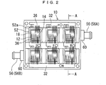
- FIG. 2 shows a plane view of a specific example of the power module 10 according to the embodiment of the present invention.
- the specific example of FIG. 2 includes six insulative substrates 18 (element blocks) that are mounted with the IGBT 12 and the diode 14. Such a configuration is a motor drive circuit generally known as a 6-in-1.
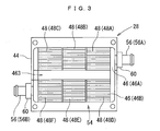
- FIG. 3 shows a state of the power module 10 shown in FIG. 2 with structural components positioned above the top plate 42 (see FIG. 1 ) removed. Both end portions facing the bottom plate 44 are fixed via a cylindrical flange 60 with a pipe 56 (56A) and a pipe 56 (56B) that serve as a flow inlet and a flow outlet of coolant, respectively.
- the channel is formed as a flow passage in which the flow direction of coolant doubles back at least once.
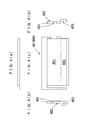
- a one-layered flow passage is formed in a center portion as shown in FIG. 6 .
- Both sides of the one-layered flow passage are formed with portions denoted by reference numerals 461, 462, 464, 465 in FIGS. 4 to 5 , whereby a two-layered flow passage having a top layer and a bottom layer is formed.
- the one-layered flow passage of the center portion does not directly contribute to cooling of the element blocks, and is provided for the purpose of doubling back the flow of coolant.
- the two intermediate plates 46A, 46B have identical shapes and are used combined so as to face away from one another.
- cooling fin 48 is divided among the six element blocks.
- a plurality of parallel flow passages is formed by cooling fins 48A, 48B, 48C, 48D, 48E, 48F of the blocks, and arranged staggered (in a zigzag configuration) such that adjacent blocks are not aligned on a straight line. In this manner, the flow of other parallel flow passages can be secured even if a portion of the passages becomes blocked.
- the route of the coolant flowing inside the condenser 28 according to the specific example of FIG. 2 is as follows.
- coolant first flows into the condenser 28 from the pipe 56A, and flows from right to left in FIG. 3 through the portions denoted by cooling fins 48A, 48B, 48C (at this time, the coolant flows through the top and bottom layers).
- the flow of coolant doubles back from left to right in FIG. 3 due to the center flow passage 463, and then the coolant flows from right to left in FIG. 3 through the portions denoted by cooling fins 48D, 48E, 48F (at this time, the coolant flows through the top and bottom layers).
- the coolant is discharged from the pipe 56B.
- the condenser 28 of the power module according to the embodiment of the present invention combines a plurality of aluminum materials 42, 44, 46, 48, 50 to form the casing 40 equipped with a channel for coolant therein. Therefore, material costs can be kept low. Moreover, thanks to the excellent workability of the aluminum materials, it is possible to adopt a configuration with a complex concave-convex configuration for a superior heat radiation performance and structure a channel for coolant with high heat radiation performance inside the casing 40. Also note that the plurality of cooling fins 48, 50 provided in the channel increases a surface area of contact with the coolant, which can improve cooling efficiency as well.
- the relatively thick bottom plate 44 secures the rigidity required by the casing 40, while the relatively thin top plate 42 can have a rigidity intentionally structured lower. In this manner, stress generated on joining surfaces of the condenser 28 and the insulative substrate 18 can be mitigated due to active deformation of the top plate 42.
- the plurality of cooling fins 48, 50 is disposed so as to extend in a direction perpendicular to the lengthwise direction of the insulative substrate 18 of the power module 10. Therefore, a reinforcement effect achieved by the rigidity of the cooling fins 48, 50 is not generated in the lengthwise direction of the insulative substrate 18, which experiences large deformation due to heat stress. On the contrary, stress generated on the joining surfaces of the condenser 28 and the insulative substrate 18 can be absorbed and mitigated by deformation in a width direction of the parallel flow passages divided by the cooling fins 48, 50.
- the condenser 28 according to the embodiment of the present invention has no risk of deformation, and therefore, the lower surface of the bottom plate 44 can be used as a fixing surface for the heat radiating part 58 (such as a DC-DC inverter and a reactor).
- the channel is divided into two or more layers consisting of a top layer and a bottom layer, and the cooling fins 48, 50 are provided in each layer, where a thickness in a height direction has been reduced. Therefore, the entire surface area of the cooling fins 48, 50 is increased, and at the same time, thanks to the cross-sectional shape of the plurality of parallel flow passages for coolant, narrow portions where the flow of coolant may back up can be eliminated (the cross-sectional shape of the flow passages in the example of FIG. 1 approaches the shape of an equilateral triangle). Widening the surface area of portions that actually contribute to heat release, namely improving a so-called fin efficiency, enables the realization of a high heat release effect.
- the channel is formed as a flow passage in which the flow direction of coolant doubles back in a Z configuration in a plane view (see FIG. 3 ). Therefore, the incorporation of a plurality of element blocks, such as with the condenser for a motor drive circuit known as a 6-in-1 shown in FIG.
- an aluminum plate is bent and shaped so as to have a wave configuration, whereby the cooling fins 48, 50 are integratedly formed having a plurality of crests and troughs.
- the cooling fins 48, 50 are integratedly formed having a plurality of crests and troughs.
- an X-ray generator 70 and an imaging device 72 are arranged so as to sandwich a half-completed power module 10' where the joining of the condenser 28 and the insulative substrate 18 is finished.
- a void transfer imaging is thus achieved by radiating X-rays in a direction perpendicular to the insulative substrate 18. Therefore, a wall of the cooling fins 48, 50 more parallel to an X-ray radiating direction results in a crown portion of the folded portions 48a, 50a of the cooling fins 48, 50 casting a more distinct shadow. As a consequence, overlapping of such a shadow with the shadow of a void increases the possibility of non-detection.
- FIG. 8 shows a relationship between an X-ray transmittance T and the apex angle ⁇ of the folded portion of the cooling fin in the power module 10', as verified by the inventors. As evident in this figure, an apex angle ⁇ less than 40° is clearly associated with a sudden drop in the X-ray transmittance T.
- the folded portions 48a, 50a of the cooling fins 48, 50 are fixed to the top plate 42, the bottom plate 44, and the intermediate plate 46 in an offset state so there is no overlap in each of the layers of the channel. Therefore, it is possible to avoid overlapping with the shadow of the aluminum brazing filler metal at a portion where the folded portions 48a, 50a of the cooling fins 48, 50 contact the top plate 42, the bottom plate 44, and the intermediate plate 46. Accordingly, the defect of the aluminum brazing filler metal casting a distinct shadow and hiding the shadow of a void can be avoided.
- the intermediate plate 46 is surely formed with the trough 46a that engages with the folded portions 48a, 50a, of the cooling fins 48, 50. Therefore, the folded portions 48a, 50a are positioned with respect to the intermediate plate 46, and an offset state in which the folded portions 48a, 50a of the cooling fins 48, 50 do not overlap in each layer of the channel can be reliably achieved.
- engaging the trough 46a with the folded portions 48a, 50a of the cooling fins 48, 50 increases a contact surface area between the intermediate plate 46 and the cooling fins 48, 50, making it possible to improve the joining reliability and joining strength of both.
- the power module 10 according to the embodiment of the present invention becomes a low-cost power module with high durability and high heat radiation performance.
Landscapes
- Cooling Or The Like Of Semiconductors Or Solid State Devices (AREA)
- Cooling Or The Like Of Electrical Apparatus (AREA)
Abstract
Description
- The present invention relates to a condenser for a power module and a power module.
- The performance of a power module equipped with a power semiconductor element such as an IGBT can be reduced due to heat generated from conducted electricity. Therefore, an insulative substrate (ceramic-based) mounted with a power semiconductor element is conventionally fixed to a heat sink, condenser, or the like and such cooling means are used to release heat.
- However, since the insulative substrate has been directly attached to the condenser in the past, there is stress generated from the difference in the linear expansion coefficients of the condenser and the insulative substrate, which carries the risks of cracks forming in joining boundary surfaces and deformation of the condenser. Current countermeasures include employing a material with a linear expansion coefficient similar to that of the insulative substrate, such as a metal/ceramic composite, for the condenser, and inserting between the condenser and the insulative substrate a buffer layer with a linear coefficient that is a mean of both, such as molybdenum (see
Patent Documents 1 and 2 for examples). - Patent Document 1: Japanese Patent Application Publication No.
JP-A-2002-78356 - Patent Document 2: Japanese Patent Application Publication No.
JP-A-2001-77260 - However, a condenser manufactured using a metal/ceramic composite is extremely expensive due to the special materials involved. For example, such a condenser may cost approximately ten to twenty times more than a condenser manufactured using a single metal such as aluminum. The use of a metal/ceramic composite requires a casting method such as the gravity casting process or the like for processing, which limits shaping flexibility. The adoption of a configuration with a good heat radiation performance such as one provided with a plurality of minute cooling fins is also difficult.
- According to the method in which the condenser itself uses an ordinary metal such as copper or aluminum and a buffer layer is inserted between the condenser and the insulative substrate, while it is possible to suppress an increase in manufacturing cost, there are other problems associated with the manufacturing process. For example, in order to join a molybdenum buffer layer with the condenser, it is necessary to heat the entire work to 300°C or more if a brazing filler metal such as solder is used. Because of the difference in the linear expansion coefficients of the buffer layer and the condenser, after heating and during cooling warpage occurs in the condenser. Warpage of the condenser suggests that there is residual stress on the joining surface and that cracks may appear in the future. In addition, warpage of the condenser can also potentially interfere with the attachment of separate parts to the condenser. Such problems concerning warpage and cracks caused by the difference in the linear expansion coefficients of the buffer layer and the condenser are difficult to avoid, regardless of what kind of material is used for the buffer layer, so long as there is a difference between both linear expansion coefficients.
- The present invention was devised in light of the foregoing issues, and it is an object of the present invention to prevent deformation of a condenser and prevent a crack from occurring at joined portions of the condenser and an insulative substrate of a power module, which are caused by a difference in linear expansion coefficients of the condenser and the insulative substrate, while also avoiding an increase in a manufacturing cost of the condenser.
- In order to resolve the above issues, a condenser for a power module according to the present invention combines a plurality of aluminum materials to form a casing equipped with a channel for coolant therein. Therefore, an increase in material costs can be prevented. Moreover, it is possible to adopt a configuration with a complex concave-convex configuration for a superior heat radiation performance. By adopting a stress relaxation structure for the mitigating stress generated on the joining surfaces of the aluminum material and the insulative substrate, the difference in the linear expansion coefficients of the aluminum material and the insulative substrate can be eliminated.
- In addition, a power module according to the present invention fixes the insulative substrate mounted with a power semiconductor element to the condenser, which consequently achieves a low-cost power module with high durability and high heat radiation performance.
- The following form of the invention is an example of the configuration of the present invention, and will be explained in an itemized manner to facilitate understanding of the diverse structures of the present invention. The items do not limit a technical scope of the present invention. Taking into consideration a best mode for carrying out the invention, items with some structural elements replaced, removed, or further including other structural elements can also be included in the technical scope of the invention in the present application.
- (1) A condenser for a power module combines a plurality of aluminum materials to form a casing equipped with a channel for coolant therein.
- According to the condenser for a power module described in the present item, combining the plurality of aluminum materials forms the casing equipped with the channel for coolant therein. Therefore, material costs can be kept low. Moreover, thanks to the excellent workability of the aluminum materials, it is possible to adopt a configuration with a complex concave-convex configuration for a superior heat radiation performance, and structure a channel for coolant with high heat radiation performance therein.
- (2) In the condenser for a power module in item (1), the casing is formed such that a thickness ratio of a top plate and a bottom plate thereof is 1:5 to 10.
- According to the condenser for a power module described in the present item, a relatively thick bottom plate secures the rigidity required by the casing, while a relatively thin top plate can have a rigidity intentionally structured lower. In this manner, stress generated on joining surfaces of the condenser and the insulative substrate can be mitigated due to active deformation of the top plate.
- (3) In the condenser for a power module in item (1), the top plate of the casing is fixed with a high-purity aluminum block for fixing the power module.
- According to the condenser for a power module described in the present item, by fixing the high-purity aluminum block to the top plate and fixing the insulative substrate to the aluminum block, stress generated on the joining surfaces of the condenser and the insulative substrate can be mitigated due to active deformation of the high-purity aluminum block, thanks to the low yield stress characteristic of the high-purity aluminum block.
- In order to lower the yield stress of the aluminum block, the aluminum purity is preferably 99.99% or more. Also, the aluminum block should preferably have a thickness that ensures sufficient realization of the stress relaxation effect of the aluminum block. For example, the aluminum block may be formed such that the thickness ratio of the top plate of the casing and the aluminum block is 1:5 to 10.
- (4) In the condenser for a power module in item (1), a frame-like projection or depression is formed at a position on the top plate that surrounds the high-purity aluminum block.
- According to the condenser for a power module described in the present item, stress concentrates on the frame-like projection or depression formed at a position surrounding the high-purity aluminum block and the frame-like projection or depression actively deforms. Therefore, stress generated on the joining surface of the condenser and the insulative substrate can be mitigated.
- (5) In the condenser for a power module in item (1), the channel is divided into a plurality of parallel flow passages by a plurality of cooling fins that extend in a direction perpendicular to a lengthwise direction of an insulative substrate of the power module.
- According to the condenser for a power module described in the present item, the plurality of cooling fins provided in the channel increases a surface area of contact with the coolant, which can improve cooling efficiency. In addition, the plurality of cooling fins is disposed so as to extend in a direction perpendicular to the lengthwise direction of the insulative substrate of the power module. Therefore, a reinforcement effect achieved by the rigidity of the cooling fins is not generated in the lengthwise direction of the insulative substrate, which experiences large deformation due to heat stress. On the contrary, stress generated on the joining surfaces of the condenser and the insulative substrate can be absorbed and mitigated by deformation in a width direction of the parallel flow passages divided by the cooling fins.
- (6) In the condenser for a power module, a plurality of aluminum materials is combined to form a casing equipped with a channel for coolant therein, the casing is formed such that a thickness ratio of a top plate and a bottom plate thereof is 1:5 to 10, the top plate is fixed with a high-purity aluminum block for fixing the power module, a frame-like projection or depression is formed at a position on the top plate that surrounds the high-purity aluminum block, and the channel is divided into a plurality of parallel flow passages by a plurality of cooling fins that extend in a direction perpendicular to a lengthwise direction of an insulative substrate of the power module (claim 1).
- According to the condenser for a power module described in the present item, combining the plurality of aluminum materials forms the casing equipped with the channel for coolant therein. Therefore, material costs can be kept low. Moreover, thanks to the excellent workability of the aluminum materials, it is possible to adopt a configuration with a complex concave-convex configuration for a superior heat radiation performance, and structure a channel for coolant with high heat radiation performance therein. A relatively thick bottom plate secures the rigidity required by the casing, while a relatively thin top plate can have a rigidity intentionally structured lower. In this manner, stress generated on joining surfaces of the condenser and the insulative substrate can be mitigated due to active deformation of the top plate. By fixing the high-purity aluminum block to the top plate and fixing the insulative substrate to the aluminum block, stress generated on the joining surfaces of the condenser and the insulative substrate can be mitigated due to active deformation of the high-purity aluminum block, thanks to the low yield stress characteristic of the high-purity aluminum block. Stress concentrates on the frame-like projection or depression formed at a position surrounding the high-purity aluminum block and the frame-like projection or depression actively deforms. Therefore, stress generated on the joining surface of the condenser and the insulative substrate can be mitigated. The plurality of cooling fins provided in the channel increases a surface area of contact with the coolant, which can improve cooling efficiency. In addition, the plurality of cooling fins is disposed so as to extend in a direction perpendicular to the lengthwise direction of the insulative substrate of the power module. Therefore, a reinforcement effect achieved by the rigidity of the cooling fins is not generated in the lengthwise direction of the insulative substrate, which experiences large deformation due to heat stress. On the contrary, stress generated on the joining surfaces of the condenser and the insulative substrate can be absorbed and mitigated by deformation in a width direction of the parallel flow passages divided by the cooling fins.
- The combination of the stress relaxation effects and cooling efficiency improvement effects obtained by the above structural elements makes it possible to avoid deformation of the condenser and cracks in the joining portions of the condenser and the insulative substrate, whereby a high heat release effect can be realized.
- (7) In the condenser for a power module, an intermediate plate is sandwiched between the top plate and the bottom plate to divide the channel into two layers, a top layer and a bottom layer, and each layer is divided into a plurality of parallel flow passages by the cooling fins (claim 2).
- According to the condenser for a power module described in the present item, sandwiching an intermediate plate between the top plate and the bottom plate divides the channel into two layers, a top layer and a bottom layer. The cooling fins are provided in each layer, where a thickness in a height direction has been reduced. Therefore, the entire surface area of the cooling fins is increased, and at the same time, thanks to the cross-sectional shape of the plurality of parallel flow passages for coolant, the flow of coolant can be prevented from backing up in narrow portions. Widening the surface area of portions that actually contribute to heat release, namely improving a so-called fin efficiency, enables the realization of a high heat release effect.
- (8) In the condenser for a power module, a plurality of intermediate plates is incorporated in a combined state between the top plate and the bottom plate to form the channel as a flow passage in which a flow direction of coolant doubles back at least once (claim 3).
- According to the condenser for a power module described in the present item, by sandwiching the plurality of intermediate plates in a combined state between the top plate and the bottom plate, the channel is formed as a flow passage in which the flow direction of coolant doubles back at least once. Therefore, the flow of coolant over the entire condenser is smoothed regardless of the wideness or narrowness of the surface area of the condenser (a surface area of the insulative substrate fixed to the condenser) to enable the realization of a high heat release effect.
- (9) In the condenser for a power module, a pipe that serves as a flow inlet and flow outlet for coolant is attached by an aluminum brazing filler metal to the top plate, the bottom plate, the plurality of intermediate plates, the cooling fin, and the insulative substrate.
- According to the condenser for a power module described in the present item, the top plate, the bottom plate, the plurality of intermediate plates, the cooling fin, the insulative substrate, and the pipe are all fixed at once through use of the aluminum brazing filler metal.
- (10) In the condenser for a power module, the cooling fin has a corrugated sheet configuration formed by folding an aluminum plate, and an apex angle of folded portions thereof is formed so as to be 40° or more (claim 4).
- According to the condenser for a power module described in the present item, since the cooling fin has a corrugated sheet configuration formed by folding an aluminum plate, the cooling fin with a plurality of crests and troughs is an integrated structure. When inspecting for bubble defects (voids) in solder, which is the joining material used to mount the power semiconductor element on an upper surface of the insulative substrate using transmission X-rays, it is possible to prevent defects from being hidden by the shadows of voids and cooling fins by forming the apex angle θ of the folded portions so as to be 40° or more. In other words, a wall of the cooling fin more parallel to an X-ray radiating direction results in a crown portion of the folded portions of the cooling fin casting a more distinct shadow. As a consequence, overlapping of a bubble defect in solder with the shadow of a void increases the possibility of non-detection. Meanwhile, if the apex angle of the folded portions of the cooling fin is 40° or more, a thickness of the cooling fin in a direction that intersects with the X-rays can be reduced, and the defect of a hidden void shadow caused by the shadow of the crown portion of the folded portions of the cooling fin can be avoided.
- (11) In the condenser for a power module, the folded portions of the cooling fin are fixed to the top plate, the bottom plate, and the intermediate plate in an offset state so there is no overlap in each of the layers of the channel (claim 5).
- According to the condenser for a power module described in the present item, the folded portions of the cooling fin are fixed to the top plate, the bottom plate, and the intermediate plate in an offset state so there is no overlap in each of the layers of the channel. Therefore, it is possible to avoid overlapping with the shadow of the aluminum brazing filler metal fillet at a portion where the folded portions of the cooling fin contact the top plate, the bottom plate, and the intermediate plate. Accordingly, the defect of the aluminum brazing filler metal fillet casting a distinct shadow and hiding the shadow of a void can be avoided.
- (12) In the condenser for a power module, the plurality of intermediate plates is formed with a trough that engages with the folded portions of the cooling fin.
- According to the condenser for a power module described in the present item, the intermediate plate is formed with the trough that engages with the folded portions of the cooling fin. Therefore, the folded portions are accurately positioned with respect to the intermediate plate, and an offset state in which the folded portions of the cooling fin do not overlap in each layer of the channel can be reliably achieved. In addition, engaging the trough with the folded portions of the cooling fin increases a contact surface area between the intermediate plate and the cooling fins, making it possible to improve the joining reliability and joining strength of both.
- (13) In the power module, the high-purity aluminum block is fixed with an insulative substrate mounted with a power semiconductor element (claim 7).
- According to the power module described in the present item, the insulative substrate mounted with a power semiconductor element is fixed to the condenser described in the above items (1) to (12), which consequently structures a low-cost power module with high durability and high heat radiation performance.
- With the present invention structured as described above, it is possible to prevent deformation of a condenser and prevent a crack from occurring at joined portions of the condenser and an insulative substrate of a power module, which are caused by a difference in linear expansion coefficients of the condenser and the insulative substrate, while also avoiding an increase in a manufacturing cost of the condenser.
-
- [0039]
FIG. 1 is a cross-sectional view schematically showing a basic structure of a power module according to an embodiment of the present invention; -
FIG. 2 is a plane view showing a specific example of the power module according to the embodiment of the present invention; -
FIG. 3 is a plane view showing a state of the power module shown inFIG. 2 with structural components positioned above a top plate removed; -
FIG. 4 is a view of a single intermediate plate of the power module shown inFIG. 2 , where (a) is a back view, (b) is a left side view, (c) is a plane view, and (d) is a right side view; -
FIG. 5 is a view of another single intermediate plate of the power module shown inFIG. 2 , where (a) is a left side view, (b) is a plane view, (c) is a right side view, and (d) is a front view; -
FIG. 6 is a cross-sectional view taken along a line A-A inFIG. 2 ; -
FIG. 7 is a schematic structural view of an inspection device for an aluminum brazing filler solder quality of the power module according to the embodiment of the present invention; and -
FIG. 8 was obtained based on the inspection device inFIG. 7 , and is a graph showing a relationship between an apex angle of a folded portion of a cooling fin and X-ray transmittance. -
- 10
- POWER MODULE
- 12
- IGBT
- 14
- DIODE
- 16
- SOLDER
- 18
- INSULATIVE SUBSTRATE
- 26
- HIGH-PURITY ALUMINUM BLOCK
- 28
- CONDENSER
- 30
- BOND
- 40
- CASING
- 42
- TOP PLATE
- 44
- BOTTOM PLATE
- 46, 46A, 46B
- INTERMEDIATE PLATE
- 48, 50
- COOLING FIN
- 52
- FRAME-LIKE PROJECTION OR DEPRESSION
- 56
- PIPE
- Hereinafter, best modes for carrying out the present invention will be described with reference to the accompanying drawings. Note that like reference numerals are assigned to portions that are identical or correspond to that of related art, and such portions are not explained in detail.
- A
power module 10 according to an embodiment of the present invention has the basic structure shown inFIG. 1 . AnIGBT 12 and adiode 14 are fixed to aninsulative substrate 18 viasolder 16. Theinsulative substrate 18 has a three-layered structure in which an upper surface of a thinceramic plate 22 is formed with aconductive wiring layer 20 and a lower surface of the thinceramic plate 22 is formed with a joininglayer 24. It should be noted that theconductive wiring layer 20 and the joininglayer 24 are both formed from a thin aluminum plate, and a surface of theconductive wiring layer 20 has nickel plating. Theinsulative substrate 18 is fixed to acondenser 28 via a high-purity aluminum block 26. The high-purity aluminum block 26 preferably has an aluminum purity of 99.99% or more for reasons that will be explained later. In addition, an aluminum brazing filler metal is used for a joiningmaterial 30 between theinsulative substrate 18, the high-purity aluminum block 26, and thecondenser 28. Aresin housing 34 equipped with abus bar 32 surrounds theinsulative substrate 18 and the high-purity aluminum block 26, and is fixed to an upper surface of thecondenser 28 using a silicon-based adhesive. Furthermore, thebus bar 32, theIGBT 12, thediode 14, and theconductive wiring layer 20 are all electrically connected by analuminum wire 36, and an interior space of theresin housing 34 is filled with asilicon gel 38. - The
condenser 28 combines a plurality of aluminum materials to form acasing 40 equipped with a channel for coolant therein. Thecasing 40 consists of the structural members of atop plate 42, abottom plate 44, anintermediate plate 46, and coolingfins - The
top plate 42 and thebottom plate 44 are formed so as to have a thickness ratio of 1:5 to 10. The high-purity aluminum block 26 is fixed with thetop plate 42. A position at which thetop plate 42 surrounds the high-purity aluminum block 26 is formed with a frame-like projection ordepression 52. In addition, thebottom plate 44 is shaped as a lidless box whose outer peripheral portion is formed with aseat portion 54 for mounting thetop plate 42 and theintermediate plate 46. Thebottom plate 44 is also fixed with apipe 56 that serves as a flow inlet and flow outlet for coolant. A lower surface of thebottom plate 44 is flat so that it may be used as a fixing surface for a heat radiating part 58 (such as a DC-DC inverter and a reactor). Theheat radiating part 58 is fixed to the lower surface of thebottom plate 44 via grease. Note that as an example of the thickness ratio of respective structural parts of thecasing 40, if a thickness t48, 50 of the coolingfins intermediate plate 46 is 4, a thickness t42 of thetop plate 42 is 8, a thickness t44 of thebottom plate 44 is 80, and a thickness t26 of thealuminum block 26 is 80. - By sandwiching the
intermediate plate 46 between thetop plate 42 and thebottom plate 44, the channel of coolant is divided into two layers, a top layer and a bottom layer, and the coolingfins fins insulative substrate 18. It should be noted that a structure divided into more layers can be adopted as necessary. By contacting and fixing the foldedportions top plate 42, thebottom plate 44, and theintermediate plate 46, the channel of the coolant is divided into a plurality of parallel flow passages. Moreover, as an enlarged portion inFIG. 1 illustrates, theintermediate plate 46 is formed with atrough 46a that engages with the foldedportions fins - Note that, for reasons to be explained later, an apex angle θ of the folded
portions portions fins top plate 42, thebottom plate 44, and theintermediate plate 46 in an offset state so there is no overlap in each of the layers of the channel. -
FIG. 2 shows a plane view of a specific example of thepower module 10 according to the embodiment of the present invention. The specific example ofFIG. 2 includes six insulative substrates 18 (element blocks) that are mounted with theIGBT 12 and thediode 14. Such a configuration is a motor drive circuit generally known as a 6-in-1. In addition,FIG. 3 shows a state of thepower module 10 shown inFIG. 2 with structural components positioned above the top plate 42 (seeFIG. 1 ) removed. Both end portions facing thebottom plate 44 are fixed via acylindrical flange 60 with a pipe 56 (56A) and a pipe 56 (56B) that serve as a flow inlet and a flow outlet of coolant, respectively. By incorporating theintermediate plate 46 between thetop plate 42 and thebottom plate 44 in a state where twointermediate plates FIGS. 4 and5 , the channel is formed as a flow passage in which the flow direction of coolant doubles back at least once. - Specifically, by vertically overlapping a portion denoted by
reference numeral 463 inFIGS. 4 and5 , a one-layered flow passage is formed in a center portion as shown inFIG. 6 . Both sides of the one-layered flow passage are formed with portions denoted byreference numerals FIGS. 4 to 5 , whereby a two-layered flow passage having a top layer and a bottom layer is formed. The one-layered flow passage of the center portion does not directly contribute to cooling of the element blocks, and is provided for the purpose of doubling back the flow of coolant. Note that in the present embodiment, the twointermediate plates - As the plane view of
FIG. 3 shows, the coolingfin 48 is divided among the six element blocks. A plurality of parallel flow passages is formed by coolingfins - The route of the coolant flowing inside the
condenser 28 according to the specific example ofFIG. 2 is as follows. InFIG. 3 , coolant first flows into thecondenser 28 from thepipe 56A, and flows from right to left inFIG. 3 through the portions denoted by coolingfins FIG. 3 due to thecenter flow passage 463, and then the coolant flows from right to left inFIG. 3 through the portions denoted by coolingfins pipe 56B. - Effects obtained by the embodiment of the present invention with the above structure are as follows. The
condenser 28 of the power module according to the embodiment of the present invention combines a plurality ofaluminum materials casing 40 equipped with a channel for coolant therein. Therefore, material costs can be kept low. Moreover, thanks to the excellent workability of the aluminum materials, it is possible to adopt a configuration with a complex concave-convex configuration for a superior heat radiation performance and structure a channel for coolant with high heat radiation performance inside thecasing 40. Also note that the plurality of coolingfins - The relatively thick
bottom plate 44 secures the rigidity required by thecasing 40, while the relatively thintop plate 42 can have a rigidity intentionally structured lower. In this manner, stress generated on joining surfaces of thecondenser 28 and theinsulative substrate 18 can be mitigated due to active deformation of thetop plate 42. - By fixing the high-
purity aluminum block 26 to thetop plate 42 and fixing theinsulative substrate 18 to thealuminum block 26, stress generated on the joining surfaces of thecondenser 28 and theinsulative substrate 18 can be mitigated due to active deformation of the high-purity aluminum block 26, thanks to the low yield stress characteristic of the high-purity aluminum block 26. Accordingly, a lower yield stress characteristic can be expected from the use of analuminum block 26 with higher aluminum purity. Stress concentrates on the frame-like projection ordepression 52 formed at a position surrounding the high-purity aluminum block 26 and the frame-like projection ordepression 52 actively deforms. Therefore, stress generated on the joining surface of thecondenser 28 and theinsulative substrate 18 can be mitigated. In addition, the plurality of coolingfins insulative substrate 18 of thepower module 10. Therefore, a reinforcement effect achieved by the rigidity of the coolingfins insulative substrate 18, which experiences large deformation due to heat stress. On the contrary, stress generated on the joining surfaces of thecondenser 28 and theinsulative substrate 18 can be absorbed and mitigated by deformation in a width direction of the parallel flow passages divided by the coolingfins - The combination of the stress relaxation effects and cooling efficiency improvement effects obtained by the above structural elements makes it possible to avoid deformation of the
condenser 28 and cracks in the joining portions of thecondenser 28 and theinsulative substrate 18, whereby a high heat release effect can be realized. - Note that the
condenser 28 according to the embodiment of the present invention has no risk of deformation, and therefore, the lower surface of thebottom plate 44 can be used as a fixing surface for the heat radiating part 58 (such as a DC-DC inverter and a reactor). - In the
condenser 28 of the power module according to the embodiment of the present invention, by sandwiching theintermediate plate 46 between thetop plate 42 and thebottom plate 44, the channel is divided into two or more layers consisting of a top layer and a bottom layer, and the coolingfins fins FIG. 1 approaches the shape of an equilateral triangle). Widening the surface area of portions that actually contribute to heat release, namely improving a so-called fin efficiency, enables the realization of a high heat release effect. - Furthermore, in the
condenser 28 for the power module according to the embodiment of the present invention, by sandwiching the twointermediate plates top plate 42 and thebottom plate 44, the channel is formed as a flow passage in which the flow direction of coolant doubles back in a Z configuration in a plane view (seeFIG. 3 ). Therefore, the incorporation of a plurality of element blocks, such as with the condenser for a motor drive circuit known as a 6-in-1 shown inFIG. 2 , smoothes the flow of coolant over theentire condenser 28 regardless of the wideness or narrowness of the surface area, even in cases of an increased surface area of the condenser 28 (a surface area of theinsulative substrate 18 fixed to the condenser) to enable the realization of a high heat release effect. - In the
condenser 28 for the power module according to the embodiment of the present invention, an aluminum plate is bent and shaped so as to have a wave configuration, whereby the coolingfins portions - Here, as shown in
FIG. 7 , for the inspection of power module solder quality (voids), anX-ray generator 70 and animaging device 72 are arranged so as to sandwich a half-completed power module 10' where the joining of thecondenser 28 and theinsulative substrate 18 is finished. A void transfer imaging is thus achieved by radiating X-rays in a direction perpendicular to theinsulative substrate 18. Therefore, a wall of the coolingfins portions fins portions fins fins FIG. 8 shows a relationship between an X-ray transmittance T and the apex angle θ of the folded portion of the cooling fin in the power module 10', as verified by the inventors. As evident in this figure, an apex angle θ less than 40° is clearly associated with a sudden drop in the X-ray transmittance T. - In the
condenser 28 for the power module according to the embodiment of the present invention, the foldedportions fins top plate 42, thebottom plate 44, and theintermediate plate 46 in an offset state so there is no overlap in each of the layers of the channel. Therefore, it is possible to avoid overlapping with the shadow of the aluminum brazing filler metal at a portion where the foldedportions fins top plate 42, thebottom plate 44, and theintermediate plate 46. Accordingly, the defect of the aluminum brazing filler metal casting a distinct shadow and hiding the shadow of a void can be avoided. - Moreover, in the
condenser 28 for the power module according to the embodiment of the present invention, theintermediate plate 46 is surely formed with thetrough 46a that engages with the foldedportions fins portions intermediate plate 46, and an offset state in which the foldedportions fins trough 46a with the foldedportions fins intermediate plate 46 and the coolingfins - Accordingly, by fixing the
insulative substrate 18 mounted with thepower semiconductor element 12 to thecondenser 28, thepower module 10 according to the embodiment of the present invention becomes a low-cost power module with high durability and high heat radiation performance.
Claims (7)
- A condenser for a power module characterized in that
a plurality of aluminum materials is combined to form a casing equipped with a channel for coolant therein,
the casing is formed such that a thickness ratio of a top plate and a bottom plate thereof is 1:5 to 10,
the top plate is fixed with a high-purity aluminum block for fixing the power module,
one of a frame-like projection and depression is formed at a position on the top plate that surrounds the high-purity aluminum block, and
the channel is divided into a plurality of parallel flow passages by a plurality of cooling fins that extend in a direction perpendicular to a lengthwise direction of an insulative substrate of the power module. - The condenser for a power module according to claim 1, characterized in that an intermediate plate is sandwiched between the top plate and the bottom plate to divide the channel into two layers, a top layer and a bottom layer, and each layer is divided into a plurality of parallel flow passages by the cooling fins.
- The condenser for a power module according to claim 1 or 2, characterized in that a plurality of intermediate plates is incorporated in a combined state between the top plate and the bottom plate to form the channel as a flow passage in which a flow direction of coolant doubles back at least once.
- The condenser for a power module according to any one of claims 1 to 3, characterized in that the cooling fin has a corrugated sheet configuration formed by folding an aluminum plate, and an apex angle of folded portions thereof is formed so as to be 40° or more.
- The condenser for a power module according to claim 4, characterized in that the folded portions of the cooling fin are fixed to the top plate, the bottom plate, and the intermediate plate in an offset state so there is no overlap in each of the layers of the channel.
- The condenser for a power module according to claim 4 or 5, characterized in that the plurality of intermediate plates is formed with a trough that engages with the folded portions of the cooling fin.
- A power module characterized in that the high-purity aluminum block is fixed with an insulative substrate mounted with a power semiconductor element.
Applications Claiming Priority (2)
| Application Number | Priority Date | Filing Date | Title |
|---|---|---|---|
| JP2007133981A JP4697475B2 (en) | 2007-05-21 | 2007-05-21 | Power module cooler and power module |
| PCT/JP2008/053711 WO2008142892A1 (en) | 2007-05-21 | 2008-02-25 | Cooler for power module and power module |
Publications (3)
| Publication Number | Publication Date |
|---|---|
| EP2040293A1 true EP2040293A1 (en) | 2009-03-25 |
| EP2040293A4 EP2040293A4 (en) | 2016-05-04 |
| EP2040293B1 EP2040293B1 (en) | 2018-03-28 |
Family
ID=40031611
Family Applications (1)
| Application Number | Title | Priority Date | Filing Date |
|---|---|---|---|
| EP08721131.4A Ceased EP2040293B1 (en) | 2007-05-21 | 2008-02-25 | Cooler for power module and power module |
Country Status (5)
| Country | Link |
|---|---|
| US (1) | US7839641B2 (en) |
| EP (1) | EP2040293B1 (en) |
| JP (1) | JP4697475B2 (en) |
| CN (1) | CN101542725B (en) |
| WO (1) | WO2008142892A1 (en) |
Cited By (3)
| Publication number | Priority date | Publication date | Assignee | Title |
|---|---|---|---|---|
| US20100180441A1 (en) * | 2009-01-20 | 2010-07-22 | Toyota Jidosha Kabushiki Kaisha | Method of brazing heat sink |
| CN104105938A (en) * | 2011-08-09 | 2014-10-15 | 丰田自动车株式会社 | Heat exchanger |
| EP3686927A1 (en) * | 2019-01-22 | 2020-07-29 | LG Electronics Inc. | Switching semiconductor device |
Families Citing this family (38)
| Publication number | Priority date | Publication date | Assignee | Title |
|---|---|---|---|---|
| JP4436843B2 (en) | 2007-02-07 | 2010-03-24 | 株式会社日立製作所 | Power converter |
| JP5381561B2 (en) * | 2008-11-28 | 2014-01-08 | 富士電機株式会社 | Semiconductor cooling device |
| JP2010171279A (en) * | 2009-01-23 | 2010-08-05 | Toyota Motor Corp | Heat radiator |
| EP2432012A4 (en) * | 2009-05-11 | 2014-04-16 | Toyota Motor Co Ltd | HEAT EXCHANGER, SEMICONDUCTOR DEVICE, METHOD FOR MANUFACTURING THE HEAT EXCHANGER, AND METHOD FOR MANUFACTURING THE SEMICONDUCTOR DEVICE |
| CN102439715B (en) * | 2009-05-19 | 2014-07-30 | 丰田自动车株式会社 | Heat exchanger and method of manufacturing the same |
| US8064198B2 (en) * | 2009-06-29 | 2011-11-22 | Honda Motor Co., Ltd. | Cooling device for semiconductor element module and magnetic part |
| JP4920071B2 (en) * | 2009-11-12 | 2012-04-18 | 株式会社日本自動車部品総合研究所 | Semiconductor device cooling device |
| TWI394524B (en) * | 2010-02-10 | 2013-04-21 | Delta Electronics Inc | Modularized heat dissipating apparatus |
| JP2011196983A (en) * | 2010-02-23 | 2011-10-06 | I-Bit Co Ltd | Fluoroscopic inspection device |
| JP5593864B2 (en) * | 2010-06-10 | 2014-09-24 | トヨタ自動車株式会社 | Semiconductor device cooler |
| JP5563383B2 (en) * | 2010-06-21 | 2014-07-30 | 日立オートモティブシステムズ株式会社 | Power converter |
| CN102064145A (en) * | 2010-09-28 | 2011-05-18 | 蔡乐勤 | High efficiency composite radiator and preparation method |
| DE102010043446B3 (en) * | 2010-11-05 | 2012-01-12 | Semikron Elektronik Gmbh & Co. Kg | Performance semiconductor system |
| JP5538653B2 (en) * | 2011-01-20 | 2014-07-02 | 三菱電機株式会社 | Heat sink and semiconductor device including the heat sink |
| EP2725609B1 (en) * | 2011-06-27 | 2019-11-13 | Rohm Co., Ltd. | Semiconductor module |
| JP5693419B2 (en) * | 2011-08-31 | 2015-04-01 | 三菱電機株式会社 | Electrical equipment housing |
| US8519532B2 (en) | 2011-09-12 | 2013-08-27 | Infineon Technologies Ag | Semiconductor device including cladded base plate |
| US8541875B2 (en) * | 2011-09-30 | 2013-09-24 | Alliance For Sustainable Energy, Llc | Integrated three-dimensional module heat exchanger for power electronics cooling |
| US8964401B2 (en) * | 2011-10-14 | 2015-02-24 | Sunpower Corporation | Electrical insulator casing |
| JP5588956B2 (en) * | 2011-11-30 | 2014-09-10 | 株式会社 日立パワーデバイス | Power semiconductor device |
| JP2013183022A (en) * | 2012-03-01 | 2013-09-12 | Toyota Industries Corp | Semiconductor device and manufacturing apparatus of the same |
| US20130306273A1 (en) * | 2012-05-18 | 2013-11-21 | International Business Machines Corporation | Apparatus for the compact cooling of an array of components |
| US8902582B2 (en) * | 2012-05-22 | 2014-12-02 | Lear Corporation | Coldplate for use with a transformer in an electric vehicle (EV) or a hybrid-electric vehicle (HEV) |
| CN103887267A (en) * | 2012-12-20 | 2014-06-25 | 浙江大学 | Power electronic module device with novel welding line |
| US9485889B2 (en) * | 2013-08-15 | 2016-11-01 | Eaton Corporation | Medium voltage hybrid air/liquid cooled adjustable frequency drive |
| WO2015137009A1 (en) * | 2014-03-14 | 2015-09-17 | 富士電機株式会社 | Cooling device and semiconductor device having said cooling device |
| JP6344477B2 (en) | 2014-09-17 | 2018-06-20 | 富士電機株式会社 | Semiconductor module |
| CN107078115B (en) * | 2015-04-01 | 2019-11-08 | 富士电机株式会社 | semiconductor module |
| WO2016203884A1 (en) * | 2015-06-17 | 2016-12-22 | 富士電機株式会社 | Power semiconductor module, flow path member, and power-semiconductor-module structure |
| CN108365736B (en) * | 2017-01-25 | 2020-10-16 | 泰达电子股份有限公司 | Multi-channel power supply |
| JP6816691B2 (en) * | 2017-09-29 | 2021-01-20 | 三菱電機株式会社 | Semiconductor device |
| WO2020031753A1 (en) * | 2018-08-09 | 2020-02-13 | 富士電機株式会社 | Cooler and semiconductor module |
| JP6743221B1 (en) * | 2019-03-18 | 2020-08-19 | Necプラットフォームズ株式会社 | Heat dissipation structure |
| CN111739852B (en) * | 2020-05-28 | 2022-02-15 | 佛山市国星光电股份有限公司 | A heat-dissipating substrate, a power module, a power device, and a processing method for a heat-dissipating substrate |
| CN111629545B (en) * | 2020-06-01 | 2024-06-04 | 深圳市天建通信有限公司 | Heat dissipation fixing device for communication engineering equipment |
| US12593555B2 (en) * | 2021-05-27 | 2026-03-31 | Amogreentech Co., Ltd. | Ceramic substrate with heat sink and manufacturing method thereof |
| CN114823546A (en) * | 2022-03-26 | 2022-07-29 | 华为数字能源技术有限公司 | Power module, method for manufacturing same, power converter, and power supply apparatus |
| DE102022204169A1 (en) | 2022-04-28 | 2023-11-02 | Robert Bosch Gesellschaft mit beschränkter Haftung | Electronic assembly |
Family Cites Families (27)
| Publication number | Priority date | Publication date | Assignee | Title |
|---|---|---|---|---|
| US4415025A (en) * | 1981-08-10 | 1983-11-15 | International Business Machines Corporation | Thermal conduction element for semiconductor devices |
| JPS62238653A (en) * | 1986-04-09 | 1987-10-19 | Nec Corp | Cooling structure |
| US5006924A (en) * | 1989-12-29 | 1991-04-09 | International Business Machines Corporation | Heat sink for utilization with high density integrated circuit substrates |
| US6401807B1 (en) * | 1997-04-03 | 2002-06-11 | Silent Systems, Inc. | Folded fin heat sink and fan attachment |
| JP2001148451A (en) * | 1999-03-24 | 2001-05-29 | Mitsubishi Materials Corp | Power module substrate |
| US20010033476A1 (en) * | 1999-07-15 | 2001-10-25 | Dibene Joseph T. | Thermal/mechanical springbeam mechanism for heat transfer from heat source to heat dissipating device |
| JP3529675B2 (en) | 1999-09-03 | 2004-05-24 | 株式会社東芝 | Semiconductor device and inverter device |
| US6466438B1 (en) * | 2000-04-17 | 2002-10-15 | Sui-Lin Lim | Generic external portable cooling device for computers |
| JP4134537B2 (en) * | 2000-08-09 | 2008-08-20 | 三菱マテリアル株式会社 | Power module and power module with heat sink |
| JP3645475B2 (en) | 2000-08-24 | 2005-05-11 | 株式会社東芝 | Inverter device |
| US20020195228A1 (en) * | 2001-06-07 | 2002-12-26 | International Business Machines Corporation | Thermal enhanced extended surface tape for integrated circuit heat dissipation |
| US6765793B2 (en) * | 2002-08-30 | 2004-07-20 | Themis Corporation | Ruggedized electronics enclosure |
| US6798663B1 (en) * | 2003-04-21 | 2004-09-28 | Hewlett Packard Development Company, L.P. | Heat sink hold-down with fan-module attach location |
| US7044199B2 (en) * | 2003-10-20 | 2006-05-16 | Thermal Corp. | Porous media cold plate |
| US7017655B2 (en) * | 2003-12-18 | 2006-03-28 | Modine Manufacturing Co. | Forced fluid heat sink |
| US6992382B2 (en) * | 2003-12-29 | 2006-01-31 | Intel Corporation | Integrated micro channels and manifold/plenum using separate silicon or low-cost polycrystalline silicon |
| JP4046703B2 (en) * | 2004-03-04 | 2008-02-13 | 三菱電機株式会社 | heatsink |
| US6992888B1 (en) * | 2004-03-08 | 2006-01-31 | Lockheed Martin Corporation | Parallel cooling of heat source mounted on a heat sink by means of liquid coolant |
| JP4319591B2 (en) * | 2004-07-15 | 2009-08-26 | 株式会社日立製作所 | Semiconductor power module |
| US7204298B2 (en) * | 2004-11-24 | 2007-04-17 | Lucent Technologies Inc. | Techniques for microchannel cooling |
| JP2006294971A (en) * | 2005-04-13 | 2006-10-26 | Toyota Industries Corp | Power module substrate and manufacturing method thereof |
| US20090065178A1 (en) * | 2005-04-21 | 2009-03-12 | Nippon Light Metal Company, Ltd. | Liquid cooling jacket |
| JP4687541B2 (en) * | 2005-04-21 | 2011-05-25 | 日本軽金属株式会社 | Liquid cooling jacket |
| JP4608641B2 (en) * | 2005-04-27 | 2011-01-12 | 株式会社豊田自動織機 | Power module heat sink |
| JP4617209B2 (en) * | 2005-07-07 | 2011-01-19 | 株式会社豊田自動織機 | Heat dissipation device |
| JP2007266224A (en) * | 2006-03-28 | 2007-10-11 | Kyocera Corp | Power module |
| US7808781B2 (en) * | 2008-05-13 | 2010-10-05 | International Business Machines Corporation | Apparatus and methods for high-performance liquid cooling of multiple chips with disparate cooling requirements |
-
2007
- 2007-05-21 JP JP2007133981A patent/JP4697475B2/en not_active Expired - Fee Related
-
2008
- 2008-02-25 WO PCT/JP2008/053711 patent/WO2008142892A1/en not_active Ceased
- 2008-02-25 US US12/297,894 patent/US7839641B2/en active Active
- 2008-02-25 EP EP08721131.4A patent/EP2040293B1/en not_active Ceased
- 2008-02-25 CN CN2008800002739A patent/CN101542725B/en not_active Expired - Fee Related
Cited By (5)
| Publication number | Priority date | Publication date | Assignee | Title |
|---|---|---|---|---|
| US20100180441A1 (en) * | 2009-01-20 | 2010-07-22 | Toyota Jidosha Kabushiki Kaisha | Method of brazing heat sink |
| CN104105938A (en) * | 2011-08-09 | 2014-10-15 | 丰田自动车株式会社 | Heat exchanger |
| WO2013021265A3 (en) * | 2011-08-09 | 2015-04-30 | Toyota Jidosha Kabushiki Kaisha | Heat exchanger |
| EP3686927A1 (en) * | 2019-01-22 | 2020-07-29 | LG Electronics Inc. | Switching semiconductor device |
| US11171073B2 (en) | 2019-01-22 | 2021-11-09 | Lg Electronics Inc. | Switching semiconductor device and cooling apparatus thereof |
Also Published As
| Publication number | Publication date |
|---|---|
| WO2008142892A1 (en) | 2008-11-27 |
| CN101542725B (en) | 2010-12-08 |
| US7839641B2 (en) | 2010-11-23 |
| EP2040293A4 (en) | 2016-05-04 |
| EP2040293B1 (en) | 2018-03-28 |
| CN101542725A (en) | 2009-09-23 |
| US20100170662A1 (en) | 2010-07-08 |
| JP4697475B2 (en) | 2011-06-08 |
| JP2008288495A (en) | 2008-11-27 |
Similar Documents
| Publication | Publication Date | Title |
|---|---|---|
| US7839641B2 (en) | Condenser for power module and power module | |
| EP1873827B1 (en) | Heat radiating device | |
| KR101097571B1 (en) | Semiconductor module | |
| JP6409690B2 (en) | Cooling module | |
| JP6522241B2 (en) | Power semiconductor device and method of manufacturing power semiconductor device | |
| EP2012355A2 (en) | Heat dissipation plate and semiconductor device | |
| WO2015033724A1 (en) | Power semiconductor module | |
| JPWO2017073233A1 (en) | Power semiconductor device | |
| JP3646665B2 (en) | Inverter device | |
| JP2002315357A (en) | Inverter device | |
| JP2016051878A (en) | Power semiconductor device | |
| CN114068449A (en) | Heat dissipation substrate and power module | |
| JP7237647B2 (en) | Circuit boards and electronic devices | |
| CN201741690U (en) | Light-weight power semi-conductor module | |
| JP2008258448A (en) | Bus bar and semiconductor device | |
| JP5164793B2 (en) | Power semiconductor device | |
| JP6555159B2 (en) | Cooling tube | |
| EP4199078B1 (en) | Semiconductor device and vehicle | |
| US20200105655A1 (en) | Semiconductor device and method for manufacturing thereof | |
| EP4709133A1 (en) | Dual-side cooling power modules and manufacturing methods thereof, and electrical systems | |
| JP2020107652A (en) | Electric circuit board and power module | |
| JP2002217338A (en) | Heat dissipation device for semiconductor device and method of manufacturing the same | |
| JP5365529B2 (en) | Power module | |
| CN121604817A (en) | Integrated power device and preparation method thereof | |
| JP2003318339A (en) | Heat sink and method of manufacturing the same |
Legal Events
| Date | Code | Title | Description |
|---|---|---|---|
| PUAI | Public reference made under article 153(3) epc to a published international application that has entered the european phase |
Free format text: ORIGINAL CODE: 0009012 |
|
| 17P | Request for examination filed |
Effective date: 20081103 |
|
| AK | Designated contracting states |
Kind code of ref document: A1 Designated state(s): AT BE BG CH CY CZ DE DK EE ES FI FR GB GR HR HU IE IS IT LI LT LU LV MC MT NL NO PL PT RO SE SI SK TR |
|
| AX | Request for extension of the european patent |
Extension state: AL BA MK RS |
|
| DAX | Request for extension of the european patent (deleted) | ||
| RBV | Designated contracting states (corrected) |
Designated state(s): DE FR |
|
| RAP1 | Party data changed (applicant data changed or rights of an application transferred) |
Owner name: TOYOTA JIDOSHA KABUSHIKI KAISHA |
|
| RA4 | Supplementary search report drawn up and despatched (corrected) |
Effective date: 20160405 |
|
| RIC1 | Information provided on ipc code assigned before grant |
Ipc: H01L 23/473 20060101AFI20160330BHEP |
|
| GRAP | Despatch of communication of intention to grant a patent |
Free format text: ORIGINAL CODE: EPIDOSNIGR1 |
|
| STAA | Information on the status of an ep patent application or granted ep patent |
Free format text: STATUS: GRANT OF PATENT IS INTENDED |
|
| INTG | Intention to grant announced |
Effective date: 20171027 |
|
| GRAS | Grant fee paid |
Free format text: ORIGINAL CODE: EPIDOSNIGR3 |
|
| GRAA | (expected) grant |
Free format text: ORIGINAL CODE: 0009210 |
|
| STAA | Information on the status of an ep patent application or granted ep patent |
Free format text: STATUS: THE PATENT HAS BEEN GRANTED |
|
| AK | Designated contracting states |
Kind code of ref document: B1 Designated state(s): DE FR |
|
| REG | Reference to a national code |
Ref country code: DE Ref legal event code: R096 Ref document number: 602008054580 Country of ref document: DE |
|
| REG | Reference to a national code |
Ref country code: DE Ref legal event code: R084 Ref document number: 602008054580 Country of ref document: DE |
|
| REG | Reference to a national code |
Ref country code: DE Ref legal event code: R097 Ref document number: 602008054580 Country of ref document: DE |
|
| PLBE | No opposition filed within time limit |
Free format text: ORIGINAL CODE: 0009261 |
|
| STAA | Information on the status of an ep patent application or granted ep patent |
Free format text: STATUS: NO OPPOSITION FILED WITHIN TIME LIMIT |
|
| 26N | No opposition filed |
Effective date: 20190103 |
|
| PG25 | Lapsed in a contracting state [announced via postgrant information from national office to epo] |
Ref country code: FR Free format text: LAPSE BECAUSE OF NON-PAYMENT OF DUE FEES Effective date: 20190228 |
|
| REG | Reference to a national code |
Ref country code: DE Ref legal event code: R082 Ref document number: 602008054580 Country of ref document: DE Representative=s name: WINTER, BRANDL - PARTNERSCHAFT MBB, PATENTANWA, DE Ref country code: DE Ref legal event code: R082 Ref document number: 602008054580 Country of ref document: DE Representative=s name: WINTER, BRANDL, FUERNISS, HUEBNER, ROESS, KAIS, DE Ref country code: DE Ref legal event code: R081 Ref document number: 602008054580 Country of ref document: DE Owner name: DENSO CORPORATION, KARIYA-CITY, JP Free format text: FORMER OWNER: TOYOTA JIDOSHA KABUSHIKI KAISHA, TOYOTA-SHI, AICHI-KEN, JP |
|
| PGFP | Annual fee paid to national office [announced via postgrant information from national office to epo] |
Ref country code: DE Payment date: 20210217 Year of fee payment: 14 |
|
| REG | Reference to a national code |
Ref country code: DE Ref legal event code: R119 Ref document number: 602008054580 Country of ref document: DE |
|
| PG25 | Lapsed in a contracting state [announced via postgrant information from national office to epo] |
Ref country code: DE Free format text: LAPSE BECAUSE OF NON-PAYMENT OF DUE FEES Effective date: 20220901 |