EP2037672A1 - Solid-state imaging element and imaging device using the same - Google Patents
Solid-state imaging element and imaging device using the same Download PDFInfo
- Publication number
- EP2037672A1 EP2037672A1 EP07744636A EP07744636A EP2037672A1 EP 2037672 A1 EP2037672 A1 EP 2037672A1 EP 07744636 A EP07744636 A EP 07744636A EP 07744636 A EP07744636 A EP 07744636A EP 2037672 A1 EP2037672 A1 EP 2037672A1
- Authority
- EP
- European Patent Office
- Prior art keywords
- photoelectric converter
- converter portions
- dividing line
- pixels
- electric charge
- Prior art date
- Legal status (The legal status is an assumption and is not a legal conclusion. Google has not performed a legal analysis and makes no representation as to the accuracy of the status listed.)
- Granted
Links
Images



Classifications
-
- H—ELECTRICITY
- H10—SEMICONDUCTOR DEVICES; ELECTRIC SOLID-STATE DEVICES NOT OTHERWISE PROVIDED FOR
- H10F—INORGANIC SEMICONDUCTOR DEVICES SENSITIVE TO INFRARED RADIATION, LIGHT, ELECTROMAGNETIC RADIATION OF SHORTER WAVELENGTH OR CORPUSCULAR RADIATION
- H10F39/00—Integrated devices, or assemblies of multiple devices, comprising at least one element covered by group H10F30/00, e.g. radiation detectors comprising photodiode arrays
- H10F39/80—Constructional details of image sensors
- H10F39/802—Geometry or disposition of elements in pixels, e.g. address-lines or gate electrodes
-
- H—ELECTRICITY
- H04—ELECTRIC COMMUNICATION TECHNIQUE
- H04N—PICTORIAL COMMUNICATION, e.g. TELEVISION
- H04N23/00—Cameras or camera modules comprising electronic image sensors; Control thereof
- H04N23/60—Control of cameras or camera modules
- H04N23/67—Focus control based on electronic image sensor signals
- H04N23/672—Focus control based on electronic image sensor signals based on the phase difference signals
-
- H—ELECTRICITY
- H04—ELECTRIC COMMUNICATION TECHNIQUE
- H04N—PICTORIAL COMMUNICATION, e.g. TELEVISION
- H04N25/00—Circuitry of solid-state image sensors [SSIS]; Control thereof
- H04N25/40—Extracting pixel data from image sensors by controlling scanning circuits, e.g. by modifying the number of pixels sampled or to be sampled
- H04N25/46—Extracting pixel data from image sensors by controlling scanning circuits, e.g. by modifying the number of pixels sampled or to be sampled by combining or binning pixels
-
- H—ELECTRICITY
- H04—ELECTRIC COMMUNICATION TECHNIQUE
- H04N—PICTORIAL COMMUNICATION, e.g. TELEVISION
- H04N25/00—Circuitry of solid-state image sensors [SSIS]; Control thereof
- H04N25/60—Noise processing, e.g. detecting, correcting, reducing or removing noise
- H04N25/62—Detection or reduction of noise due to excess charges produced by the exposure, e.g. smear, blooming, ghost image, crosstalk or leakage between pixels
- H04N25/621—Detection or reduction of noise due to excess charges produced by the exposure, e.g. smear, blooming, ghost image, crosstalk or leakage between pixels for the control of blooming
-
- H—ELECTRICITY
- H04—ELECTRIC COMMUNICATION TECHNIQUE
- H04N—PICTORIAL COMMUNICATION, e.g. TELEVISION
- H04N25/00—Circuitry of solid-state image sensors [SSIS]; Control thereof
- H04N25/70—SSIS architectures; Circuits associated therewith
- H04N25/702—SSIS architectures characterised by non-identical, non-equidistant or non-planar pixel layout
-
- H—ELECTRICITY
- H04—ELECTRIC COMMUNICATION TECHNIQUE
- H04N—PICTORIAL COMMUNICATION, e.g. TELEVISION
- H04N25/00—Circuitry of solid-state image sensors [SSIS]; Control thereof
- H04N25/70—SSIS architectures; Circuits associated therewith
- H04N25/703—SSIS architectures incorporating pixels for producing signals other than image signals
- H04N25/704—Pixels specially adapted for focusing, e.g. phase difference pixel sets
-
- H—ELECTRICITY
- H04—ELECTRIC COMMUNICATION TECHNIQUE
- H04N—PICTORIAL COMMUNICATION, e.g. TELEVISION
- H04N25/00—Circuitry of solid-state image sensors [SSIS]; Control thereof
- H04N25/70—SSIS architectures; Circuits associated therewith
- H04N25/76—Addressed sensors, e.g. MOS or CMOS sensors
- H04N25/77—Pixel circuitry, e.g. memories, A/D converters, pixel amplifiers, shared circuits or shared components
- H04N25/778—Pixel circuitry, e.g. memories, A/D converters, pixel amplifiers, shared circuits or shared components comprising amplifiers shared between a plurality of pixels, i.e. at least one part of the amplifier must be on the sensor array itself
-
- H—ELECTRICITY
- H10—SEMICONDUCTOR DEVICES; ELECTRIC SOLID-STATE DEVICES NOT OTHERWISE PROVIDED FOR
- H10F—INORGANIC SEMICONDUCTOR DEVICES SENSITIVE TO INFRARED RADIATION, LIGHT, ELECTROMAGNETIC RADIATION OF SHORTER WAVELENGTH OR CORPUSCULAR RADIATION
- H10F39/00—Integrated devices, or assemblies of multiple devices, comprising at least one element covered by group H10F30/00, e.g. radiation detectors comprising photodiode arrays
- H10F39/80—Constructional details of image sensors
- H10F39/813—Electronic components shared by multiple pixels, e.g. one amplifier shared by two pixels
Definitions
- the present invention relates to a solid-state imaging device and an imaging apparatus using the solid-state imaging device.
- an imaging apparatus such as a video camera and an electronic still camera has widely spread.
- a solid-state imaging device such as a CCD type and an amplification type is used.
- a plurality of pixels having a photoelectric converter portion for generating a signal charge in accordance with an amount of incident light are formed in a grid shape.
- a signal charge generated and accumulated by the photoelectric converter portion in a pixel is led to an amplifying portion, and a signal amplified by the amplifying portion is output from the pixel.
- an amplification type solid-state imaging device there is proposed, for example, a solid-state imaging device using a junction-field-effect-transistor in the amplifying portion in Japanese Patent Application Laid-Open Nos. 11-177076 and 2004-335882 , and a CMOS type solid-state imaging device using an MOS transistor in the amplifying portion in Japanese Patent Application Laid-Open No. 2004-111590 .
- a photoelectric converter portion, an amplifying portion, and a charge-storing portion for temporally storing the charge between them are disposed in each pixel.
- the signal charge generated in each photoelectric converter portion is transferred to each charge-storing portion at the same time over all pixels and temporally stored, and the signal charge is successively converted into pixel signal with a prescribed readout timing. Accordingly, it becomes possible to prevent image deformation caused by difference in exposure time of respective pixels between lines upon carrying out electronic shutter movement, which is a so-called rolling shutter.
- the pupil division phase difference detection method is a method for detecting a defocusing amount of an image-taking lens such that a bundle of rays passing through the image-taking lens is divided into two at pupil to form a pair of divided images, and difference in the images (the amount of phase shift) is detected.
- a plurality of pixels having photoelectric converter portions bisected top and bottom (bisected into a top portion and a bottom portion) and a plurality of pixels having photoelectric converter portions bisected right and left (bisected into a right portion and a left portion) are provided.
- a micro-lens is provided on such photoelectric converter portions with one-to-one correspondence to each pixel.
- the bisected photoelectric converter portion is disposed substantially an imaging relation (conjugate relation) to the exit pupil of the image-taking lens by the micro-lens.
- the bisected photoelectric converter portion is to be disposed substantially to the focal point of the micro-lens.
- one of the bisected photoelectric converter portion selectively detects a bundle of rays passing through an area, which is a portion of the exit pupil of the image-taking lens, decentered in a given direction from the center of the exit pupil, and carries out photoelectric conversion.
- the other of the bisected photoelectric converter portion selectively detects a bundle of rays passing through an area, which is a portion of the exit pupil of the image-taking lens, decentered in the opposite direction from the center of the exit pupil, and carries out photoelectric conversion.
- the reason that a plurality of pixels having an upper-and-lower bisected photoelectric converter portion and a plurality of pixels having a right-and-left bisected photoelectric converter portion are disposed is for precisely detecting a state of focusing in all directions by changing direction of pupil division so as to precisely detect phase shift amounts of mutually different directions.
- a phase shift amount in the upper-and-lower direction can be precisely detected.
- signals from a plurality of pixels having right-and-left bisected photoelectric converter portion and disposed in a right-and-left direction are used, a phase shift amount in the right-and-left direction can be precisely detected.
- the present invention is made in view of the above-described problems and has an object to provide a solid-state imaging device having a degree of freedom capable of changing which of the pixels functions as a pixel having a photoelectric converter portion bisected in which direction without causing the similar state of a defect pixel, and capable of enhancing detection accuracy of focus adjusting state, and an imaging apparatus using thereof.
- a solid-state imaging device for photoelectrically converting an object image formed by an image-taking lens comprising: a plurality of pixels disposed two-dimensionally; at least a portion of pixels among the plurality of pixels including four photoelectric converter portions each of which exists in one of four areas divided by a first direction dividing line and a second direction dividing line crossing with each other in plan view and carries out photoelectric conversion and a mode setting member capable of selectively setting in each of a first through a third modes in accordance with a control signal.
- the first mode is a mode that signals from two photoelectric converter portions locating in one side of the first direction dividing line among the four photoelectric converter portions are added, and signals from two photoelectric converter portions locating in the other side of the first direction dividing line among the four photoelectric converter portions are added, and both of the added signals are obtained independently.
- the second mode is a mode that signals from two photoelectric converter portions locating in one side of the second direction dividing line among the four photoelectric converter portions are added, and signals from two photoelectric converter portions locating in the other side of the second direction dividing line among the four photoelectric converter portions are added, and both of the added signals are obtained independently.
- the third mode is a mode that signals from the four photoelectric converter portions are added.
- a solid-state imaging device for photoelectrically converting an object image formed by an image-taking lens comprising: a plurality of pixels disposed two-dimensionally; at least a portion of pixels among the plurality of pixels including four photoelectric converter portions each of which exists in one of four areas divided by a first direction dividing line and a second direction dividing line crossing with each other in plan view and carries out photoelectric conversion and a mode setting member capable of selectively setting in each of a first through a third modes in accordance with a control signal.
- the first mode is a mode that two photoelectric converter portions locating in one side of the first direction dividing line among the four photoelectric converter portions are electrically connected, and two photoelectric converter portions locating in the other side of the first direction dividing line among the four photoelectric converter portions are electrically connected, and photoelectric converter portions located different side with respect to the first dividing line among the four photoelectric converter portions are electrically separated.
- the second mode is a mode that two photoelectric converter portions locating in one side of the second direction dividing line among the four photoelectric converter portions are electrically connected, and two photoelectric converter portions locating in the other side of the second direction dividing line among the four photoelectric converter portions are electrically connected, and photoelectric converter portions located different side with respect to the second dividing line among the four photoelectric converter portions are electrically separated.
- the third mode is a mode that two photoelectric converter portions locating in one side of the first direction dividing line among the four photoelectric converter portions, and two photoelectric converter portions locating in the other side of the first direction dividing line among the four photoelectric converter portions are electrically connected, and two photoelectric converter portions locating in one side of the second direction dividing line among the four photoelectric converter portions, and two photoelectric converter portions locating in the other side of the second direction dividing line among the four photoelectric converter portions are electrically connected.
- a space between each of the two photoelectric converter portions among the four photoelectric converter portions adjacent each other with respect to the first or the second dividing line has a photoelectric converter function when the two electric converter portions are electrically connected, and does not have a photoelectric converter function when the two electric converter portions are electrically separated.
- the mode setting member includes a first gate electrode disposed along the first dividing line and a second gate electrode disposed along the second dividing line.
- the first gate electrode constitutes a gate of an MOS transistor setting semiconductor areas of the two photoelectric converter portions locating one side of the second dividing line among the four photoelectric converter portions to be source or drain, and a gate of an MOS transistor setting semiconductor areas of the two photoelectric converter portions locating the other side of the second dividing line among the four photoelectric converter portions to be source or drain
- the second gate electrode constitutes a gate of an MOS transistor setting semiconductor areas of the two photoelectric converter portions locating one side of the first dividing line among the four photoelectric converter portions to be source or drain, and a gate of an MOS transistor setting semiconductor areas of the two photoelectric converter portions locating the other side of the first dividing line among the four photoelectric converter portions to be source or drain.
- the first and the second gate electrodes are constructed by a transparent material.
- the first and the second gate electrodes are constructed by polysilicon.
- the at least one portion of pixels include a first and a second electric charge storage portions for storing electric charge transferred from two respective photoelectric converter portions locating diagonally among the four photoelectric converter portions, an amplifier for outputting signal in accordance with an electric charge amount of a given portion, a first transfer gate for transferring electric charge from one side of photoelectric converter portion among the two photoelectric converter portions locating diagonally to the fist electric charge storage portion, a second transfer gate for transferring electric charge from the other side of photoelectric converter portion among the two photoelectric converter portions locating diagonally to the second electric charge storage portion, a third transfer gate for transferring electric charge from the first transfer gate to the given portion, and a fourth transfer gate for transferring electric charge from the second transfer gate to the given portion.
- the at least a portion of pixels includes an electric charge discharging gate for discharging electric charge from at least one photoelectric converter portion of the four photoelectric converter portions.
- a micro-lens for leading light to the four photoelectric converter portions is provided to each of at least a portion of pixels with one-to-one correspondence.
- an imaging apparatus including the solid-state imaging device according to a first aspect or a second aspect, and a signal processor for outputting detection signal indicating focusing state of the image-taking lens on the basis of signals obtained in the first mode or the second mode from each of selected pixels among at least one portion of pixels.
- a lens controller for controlling focus adjustment of the image-taking lens on the basis of the detection signal from the signal processor is included.
- a solid-state imaging device having a degree of freedom capable of changing whether which pixel is functioned as a pixel having a photoelectric converter portion bisected in which direction without causing the similar state of a defect pixel, and capable of thereby enhancing detection accuracy of focus adjusting state, and an imaging apparatus using thereof.
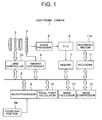
- Fig. 1 is a block diagram showing an electronic camera 1 as an imaging apparatus according to an embodiment of the present invention.
- the electronic camera 1 is equipped with an image-taking lens 2.
- the image-taking lens 2 is controlled by a lens controller 2a upon focusing and stopping down of an aperture stop.
- An imaging surface of a solid-state imaging device 3 is disposed in the image side space of the image-taking lens 2.
- the solid-state imaging device 3 is driven by an instruction of an imaging controller 4 and outputs a signal.
- the signal output from the solid-state imaging device 3 is either an imaging signal or a focal point detection signal. Either way a signal is processed by a signal processor 5 and an A/D converter 6, and stored temporarily in a memory 7.
- the memory 7 is connected to a data bus 8.
- the data bus 8 is connected with the lens controller 2a, the imaging controller 4, a microprocessor 9, a focal point calculator (detection processor) 10, a recorder 11, an image compressor 12, and an image processor 13.
- the microprocessor 9 is connected with an operating portion 9a such as a release button.
- the recorder 11 is removably connected with a recording medium 11a. Movement of the electronic camera 1 is going to be explained later with reference to Fig. 12 .
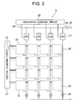
- Fig. 2 is a circuit diagram showing broad configuration of a solid-state imaging device 3 shown in Fig. 1 .
- the solid-state imaging device 3 has a plurality of pixels 20 formed in a grid shape and peripheral circuitry for outputting a signal from the pixel 20.
- the number of pixels is 16 that is four rows horizontally and four columns vertically.
- dotted line denoted by 20 shows an outline of a pixel, specific configuration and circuitry of the pixel are explained later.
- each pixel 20 has the same circuitry and plane structure.
- the pixel 20 outputs either an imaging signal or a focal point detection signal in accordance with a drive signal from peripheral circuitry.
- the whole pixels can be reset their photoelectric converter portions at the same time, so that exposure time and timing thereof can be made the same.
- Peripheral circuitry is composed of a vertical scanning circuit 21, a horizontal scanning circuit 22, drive signal lines 23 and 24 connected thereto, a vertical signal line 25 for receiving signals from pixels, a constant-current power supply 26 for connecting to the vertical signal line 25, a correlation double sampling circuit (CDS) 27, a horizontal signal line 28 for receiving signal output from the correlation double sampling circuit 27, an output amplifier 29, and the like.
- CDS correlation double sampling circuit
- the vertical scanning circuit 21 and the horizontal scanning circuit 22 output a driving signal on the basis of an instruction from the imaging controller 4 of the electronic camera 1.
- Each pixel receives the driving signal output from the vertical scanning circuit 21 through the drive signal line 23, and is driven, and outputs the imaging signal or the focal point detection signal to the vertical signal line 25.
- the vertical scanning circuit 21 outputs a plurality of drive signals. Accordingly, a plurality of drive signal lines 23 are there. This is explained later.
- the signal output from the pixel 20 is carried out predetermined noise reduction by the correlation double sampling circuit 27, and output in accordance with driving signal from the horizontal scanning circuit 22 through the horizontal signal line 28 and the output amplifier 29.
- Fig. 3 is a circuit diagram showing a pixel 20 shown in Fig. 2 .
- the pixel 20 includes four pinned photodiodes 31 through 34 as four photoelectric converter portions for generating and storing electric charge, a first and a second electric charge storage portions 35, 36 for separately storing electric charge transferred from the two pinned photodiodes 32, 33 locating diagonally, a first and a second transfer transistors 37, 38 as a first and a second transfer portions for transferring electric charge from pinned photodiodes 32, 33 to the first and the second electric charge storage portions 35, 36 respectively, a floating diffusion (FD) 40 as a designated portion, a third and a fourth transfer transistors 37, 38 as a third and a fourth transfer gate portions for transferring electric charge from the first and the second electric charge storage portions 35, 36 to the FD40 respectively, an amplifying transistor 43 as an amplifying portion for outputting signal in accordance with the amount of electric charge of FD 40, an FD reset transistor 44 as a first reset portion
- the pixel 20 includes a connection/separation transistor 51 for electrically connecting and separating pinned photodiodes 31 and 32, a connection/separation transistor 52 for electrically connecting and separating pinned photodiodes 33, 34, a connection/separation transistor 53 for electrically connecting and separating pinned photodiodes 31, 33, and a connection/separation transistor 54 for electrically connecting and separating pinned photodiodes 32, 34.
- the first through fourth transfer transistors 37, 38, 41 and 42, the amplifying transistor 43, FD reset transistor 44, the select transistor 45, PD reset transistor 46, connection/separation transistors 51 through 54 are constructed by MOS transistors. In the present embodiment, these transistors except amplifying transistor 43 become on when the gate electrode is high, and off when the gate electrode is low.
- Gate electrodes of connection/separation transistors 51, 52 are mutually connected, and mutually connected to every pixel row, and drive signal (control signal) ( ⁇ DB1 is provided from the vertical scanning circuit 21 through drive signal line 23.
- Gate electrodes of connection/separation transistors 53, 54 are mutually connected, and mutually connected to every pixel row, and drive signal (control signal) ( ⁇ PDB2 is provided from the vertical scanning circuit 21 through drive signal line 23.
- connection/separation transistors 51, 52 become on and connection/separation transistors 53, 54 become off, so that pinned photodiodes 31, 32 are electrically connected, and pinned photodiodes 33, 34 are electrically connected, on the other hand, pinned photodiodes 31, 33 are electrically separated, and pinned photodiodes 32, 34 are electrically separated.
- pinned photodiodes 31 through 34 as a whole become substantially equivalent to an upper-and-lower bisected (bisected into an upper portion and a lower portion) photoelectric converter portion. In the following explanation, this state is called as a PD upper-and-lower bisected state.
- connection/separation transistors 51, 52 become off and connection/separation transistors 53, 54 become on, so that pinned photodiodes 31, 32 are electrically separated, and pinned photodiodes 33, 34 are electrically separated, on the other hand, pinned photodiodes 31, 33 are electrically connected, and pinned photodiodes 32, 34 are electrically connected.
- pinned photodiodes 31 through 34 as a whole become substantially equivalent to a left-and-right bisected (bisected into a left portion and a right portion) photoelectric converter portion. In the following explanation, this state is called as a PD left-and-right bisected state.
- connection/separation transistors 51 through 54 become on, so that pinned photodiodes 31, 32 are electrically connected, pinned photodiodes 33, 34 are electrically connected, pinned photodiodes 31, 33 are electrically connected, and pinned photodiodes 32, 34 are electrically connected.
- pinned photodiodes 31 through 34 as a whole become substantially equivalent to an undivided photoelectric converter portion. In the following explanation, this state is called as a PD undivided state.
- the first and the second electric charge storage portions 35, 36 are provided, and electric charge generated in the pinned photodiodes 31 through 34 is temporarily stored in the first and the second electric charge storage portions 35, 36 before transferring to FD40. Accordingly, it becomes possible to make exposure time and timing thereof regarding the all pixels the same, so that not only synchronism of the image signal can be secured, but also synchronism of the signal upon focal point detection can be secured.
- the present invention is not limited to this, and it may be constructed to carry out rolling shutter without providing electric charge storage portions 35, 36.
- the first transfer transistor 37 transfers electric charge from the pinned photodiode 32 to the first electric charge storage portion 35.
- the place where the electric charge is generated differs under which state the exposure is took place such as the PD upper-and-lower bisected state, the PD left-and-right bisected state, or the PD undivided state.
- the second transfer transistor 38 transfers electric charge from the pinned photodiode 33 to the second electric charge storage portion 36.
- the place where the electric charge is generated also differs under which state the exposure is took place such as the PD upper-and-lower bisected state, the PD left-and-right bisected state, or the PD undivided state.
- Gate electrodes of the first and the second transfer transistors 37, 38 are mutually connected, and mutually connected to every pixel row, and drive signal ( ⁇ TGA is provided from the vertical scanning circuit 21 through drive signal line 23.
- the first and the second transfer transistors 37, 38 become on at the same time with a given timing in accordance with the drive signal ( ⁇ TGA, and electric charge is transferred from the two pinned photodiodes 32, 33 to the electric charge storage portions 35, 36 at the same time respectively.
- the present invention is not limited to this, for example, it may be possible to separately provide drive signal to each gate electrode so as to make the first and the second transfer transistor 37, 38 in the on state at the same time.
- the third and the fourth transfer transistors 41, 42 are separately provided drive signals. Gate electrode of the third transfer transistor 41 is mutually connected every pixel row and drive signal ⁇ TGB is provided from the vertical scanning circuit 21 through drive signal line 23. Gate electrode of the fourth transfer transistor 41 is mutually connected every pixel row, and drive signal ⁇ TGC is provided from the vertical scanning circuit 21 through drive signal line 23.
- the third and the fourth transfer transistors 41, 42 become on state with a given timing in accordance with these drive signals ( ⁇ TGB and ⁇ TGC, and transfer electric charge from the first and the second electric charge storage portions 35, 36 to the FD40 with separate timings or at the same timing.
- Gate electrode of the select transistor 45 is mutually connected every pixel row, and drive signal ⁇ S is provided from the vertical scanning circuit 21 through drive signal line 23.
- Gate electrode of the FD reset transistor 44 is mutually connected every pixel row, and drive signal ⁇ FDR is provided from the vertical scanning circuit 21 through drive signal line 23.
- Gate electrode of the PD reset transistor 46 is mutually connected every pixel row, and drive signal ⁇ PDR is provided from the vertical scanning circuit 21 through drive signal line 23.
- all of the effective pixels have the same structure, and these pixels can output either focal point detection signal or image signal.
- the present invention is not limited to this, and a focal point detection area may be provided to a given position of the solid-state imaging device 3, and pixels for outputting focal point detection signal may be disposed in the area.
- Fig. 3 one terminal of pinned photodiodes 31 through 34, one terminal of electric charge storage portions 35, 36, and one terminal of the FD40 are expediently shown to be grounded. However, as will be understood from Figs. 5 through 8 explained later, they become electric potentials of P-well 62.
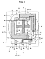
- Fig. 4 is a plan view typically showing the pixel shown in Fig. 2 .
- Figs. 5 and 6 are sectional views along A-A' line in Fig. 4 .
- Fig. 5 shows a state where the second gate electrode is low (in other words, ⁇ PDB2 is low), and the connection/separation transistor 51 is made to be off.
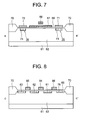
- Fig. 7 is a sectional view along B-B' line in Fig. 4 .
- Fig. 8 is a sectional view along C-C' line in Fig. 4 .
- the micro-lens is omitted.
- drive lines are omitted, except electrical connection of lines in the pixel 20.
- X direction is the right-and-left direction
- +X direction is the right side
- -X direction is the left side
- Y direction is the upper-and-lower direction
- +Y direction is the upper side
- -Y direction is the lower side.
- a P-type well 62 is formed on an N-type silicon substrate 61.
- An N-type charge storage layer 63 is formed on the P-type well 62, and by adding a P-type depletion prevention layer 64 on the surface side of the charge storage layer 63 pinned photodiodes 31 through 34 are composed.
- the construction of a pinned photodiode is adopted, the present invention is not limited to this, and the depletion prevention layer may be omitted.
- the four pinned photodiodes 31 through 34 are disposed in four areas divided by a division line B-B' in Y direction and a division line D-D' in X direction each crossing in a plane seen from Z direction.
- the pinned photodiode 31 is disposed in the upper left area
- the pinned photodiode 32 is in the upper right area
- the pinned photodiode 33 is in the lower left area
- the pinned photodiode 34 is in the lower right area among the four areas.
- These pinned photodiodes 31 through 34 are disposed near to the intersection of the division lines B-B' and D-D', and disposed rotationally symmetric around the intersection. As shown in Fig.
- a micro-lens 65 for leading incident light to the pinned photodiodes 31 through 34 is disposed.
- the micro-lens is disposed such that the centerline thereof passes through the intersection of the division lines B-B' and D-D'. Accordingly, incident light led by the micro-lens 65 is divided at the pupil and led to each pinned photodiodes 31 through 34.
- the micro-lens may be disposed such that in a pixel located near the center of the effective pixel area the center of the micro-lens comes to the intersection of the division lines B-B' and D-D', on the other hand, in the periphery of the effective pixel area the center of the micro-lens comes to a shifted position from the intersection.
- the first gate electrode 67 is disposed along the division line B-B', and the second gate electrode 68 is disposed along the division line D-D'.
- the second gate electrode 68 is formed on between the pinned photodiodes 31 and 32, and between the pinned photodiodes 33 and 34 through a thin silicon oxide layer 66.
- the second gate electrode 68 forms a gate of an MOS transistor (connection/separation transistor 51) composed of the charge storage layer 63 of the pinned photodiode 31 and the charge storage layer 63 of the pinned photodiode 32 as a source or a drain, and a gate of an MOS transistor (connection/separation transistor 52) composed of the charge storage layer 63 of the pinned photodiode 33 and the charge storage layer 63 of the pinned photodiode 34 as a source or a drain.
- the drive signal ⁇ PDB1 is provided to the second gate electrode 68 from a line (not shown).
- the first gate electrode 67 is formed on between the pinned photodiodes 31 and 33, and between the pinned photodiodes 32 and 34 through a thin silicon oxide layer 66. Accordingly, the first gate electrode 67 forms a gate of an MOS transistor (connection/separation transistor 53) composed of the charge storage layer 63 of the pinned photodiode 31 and the charge storage layer 63 of the pinned photodiode 33 as a source or a drain, and a gate of an MOS transistor (connection/separation transistor 54) composed of the charge storage layer 63 of the pinned photodiode 32 and the charge storage layer 63 of the pinned photodiode 34 as a source or a drain.
- the drive signal ⁇ PDB2 is provided to the first gate electrode 68 from a line (not shown).
- the gate electrode of the second gate electrode 68 passes over the gate electrode 67 through an insulation layer as shown in Fig. 7 .
- connection/separation transistor 51 when the second gate electrode 68 is low ( ⁇ PDB2 is low), since an inversion layer does not generated in the channel area of the connection/separation transistor 51 as shown in Fig. 5 , the connection/separation transistor 51 becomes off. On the other hand, when the second gate electrode 68 is high ( ⁇ PDB2 is high), since an inversion layer 69 is generated in the channel area of the connection/separation transistor 51, the connection/separation transistor 51 becomes on. The similar can be applied to the other connection/separation transistors 52 through 54.
- connection/separation transistors 51 through 54 become off when the voltage of the gate thereof is made to become zero potential (voltage of the substrate 1), they may be made to be on when the difference to the zero potential becomes large. Moreover, although the connection/separation transistors 51 through 54 become on when the voltage of the gate thereof is made to become zero potential (voltage of the substrate 1), they may be made to be off when negative voltage than the zero potential is applied. When the connection/separation transistors 51 through 54 are constructed to be off when the gate voltage is not applied, they become on when the positive voltage applied to the gate voltage, and when the connection/separation transistors 51 through 54 are constructed to be on when the gate voltage is not applied, they become off when the negative voltage is applied to the gate voltage.
- the first and the second gate electrodes 67, 68 are made from a transparent material such as an ITO film. Accordingly, incident light is not blocked by the first and the second gate electrodes 67, 68, and reaches the area between the pinned photodiodes 31 through 34 located under the first and the second gate electrodes 67, 68. Accordingly, for example, when the connection/separation transistor 51 is on as shown in Fig. 6 , since an inversion layer 69 formed between the pinned photodiodes 31 and 32 has a photoelectric conversion function, using efficiency of the incident light can be enhanced. On the other hand, when the connection/separation transistor 51 is off as shown in Fig.
- the first and the second gate electrodes 67, 68 may be constructed by polysilicon instead of the ITO film.
- polysilicon although transmittance becomes partly lower than that of ITO film, since it can easily be formed as a fine structure, from collective consideration, there are instances where polysilicon can further reduce amount of light loss.
- the first and the second gate electrodes 67, 68 may be constructed by a light blocking material.
- the first and the second gate electrodes 67, 68 form a mode setting means capable of selectively setting mode such as a PD upper-and-lower bisected state (a first mode), a PD left-and-right bisected state (a second mode), and a PD undivided state (a third mode) in accordance with control signals ( ⁇ PDB2 and ⁇ PDB1).
- a PD upper-and-lower bisected state signals of pinned photodiodes 31, 32 are added, and signals of pinned photodiodes 33, 34 are added, and these added signals are independently obtained.
- signals of pinned photodiodes 31, 33 are added, and signals of pinned photodiodes 32, 34 are added, and these added signals are independently obtained.
- signals of pinned photodiodes 31 through 34 are added.
- pinned photodiodes 31 through 34 are constructed to be completely electrically separated with each other, by suitably disposing charge storage portions and transfer switches so as to independently use or add signals red out from pinned photodiodes 31 through 34 in accordance with control signal, it becomes possible to realize the similar signal adding modes such as the PD left-and-right bisected state, the PD left-and-right bisected state, and the PD undivided state, so that the present invention may include such construction.
- the present invention may include such construction.
- the number of external charge storage portions and transfer switches can be reduced and wiring can be simplified, so that it is much desirable.
- gate electrodes 71, 72 are respectively formed through a thin silicon oxide film 66.
- the first and a second transfer transistors 37, 38 are constructed as MOS transistors whose gates are gate electrodes 71, 72, and whose source and drain are electric charge storage potions 35, 36 and pinned photodiodes 32, 33, respectively.
- the gate electrodes 71, 72 are connected each other with a line not shown. Accordingly, the first and the second transfer transistors 37, 38 are on and off at the same time in accordance with drive signal ⁇ TGA. Therefore, respective electric charges from pinned photodiodes 32, 33 are transferred to corresponding electric charge storage portions 35, 36 at the same time.
- the electric charge storage portions 35, 36 include N-type layers 73, 74 formed on the P-type well 62.
- the gate electrodes 71, 72 of the first and the second transfer transistor 37, 38 are disposed over upper parts of the two N-type layers 73, 74. In this manner, the electric charge storage portions 35, 36 are constructed as MOS capacitors by the gate electrodes 71, 72 and the N-type layers 73, 74.
- FD40 is constructed as substantially one floating diffusion by electrically connecting two N-type areas 75, 76 formed separately on the P-type well with a wiring 77. Electric charge is transferred from either of the two electrical charge storage portions 35 and 36 to the FD40.
- Gate electrodes 78, 79 are formed through a thin silicon oxide film 66 between the first and the second electric charge storage portions 35, 36 and N-type diffusion layer as the FD40.
- the third and the fourth transfer transistors 41, 42 are constructed as MOS transistors making the gate electrodes 78, 79 as gates, and N-type layers 71, 72 of the electric charge storage portions 35, 36 and N-type diffusion area of the FD40 as sources or drains.
- the gate electrode 78 of the third transfer transistor 41 and the gate electrode 79 of the fourth transfer transistor 42 are independently formed and supplied with independent drive signals ⁇ TGB and ⁇ TGC from the vertical scanning circuit 21. Accordingly, the third and the fourth transfer transistors 41, 42 are independently driven in accordance with respective drive signals ⁇ TGB and ⁇ TGC. Therefore, the third and the fourth transfer transistors 41, 42 can transfer electric charge from the first and the second electric charge storage portions 35, 36 either at the same time or different timings to the FD40.
- N-type diffusion layers 81 through 83 are formed along C-C' line in Fig. 4 .
- the N-type layer 81 is connected to a power supply VDD by unillustrated wiring.
- a gate electrode 84 is formed on the N-type layers 81, 82 through a thin silicon oxide film 66.
- the amplifying transistor 43 is constructed as an MOS transistor making the gate electrode 84 as a gate, and the N-type layers 81, 82 as a source or a drain.
- the gate electrode 84 is connected to the FD40 (N-type layers 75, 76) by the wiring 77.
- a gate electrode 85 is formed on a space between N-type layers 82 and 83 through a thin silicon oxide film 66.
- the select transistor 45 is constructed as an MOS transistor making the gate electrode 85 as a gate, and N-type layers 82, 83 as a source or a drain.
- a gate electrode 86 is formed on a space between N-type layers 76 and 81 through a thin silicon oxide film 66.
- the FD reset transistor 44 is constructed as an MOS transistor making the gate electrode 86 as a gate, and N-type layers 76, 81 as a source or a drain.
- N-type layer 87 is formed in P well 62.
- a gate electrode 88 is formed on a space between N-type layer 87 and the pinned photodiode 31 through a thin silicon oxide film 66.
- PD reset transistor 46 is constructed as an MOS transistor making the gate electrode 88 as a gate, and N-type layer 87 and the electric charge storage layer 63 of the pinned photodiode 31 as a source or a drain.
- Drive signal ⁇ PDR is supplied to the gate electrode 88 by an unillustrated wiring.
- a second reset portion (here, PD reset transistor 46) discharges unnecessary electric charge in the pinned photodiodes 31 through 34.
- unnecessary electric charge there are reset electric charge upon operating electric shutter and overflowed electric charge upon receiving strong incident light.
- unnecessary electric charge may be transferred to the FD40 and discharged by the first reset portion (here, FD reset transistor 44).
- the second reset portion is not necessary to be disposed.
- thick silicon oxide film 70 is formed on the circumference of the pinned photodiodes 31 through 34 and each N-type layer, and each element is separated.
- Fig. 9 is a timing chart showing drive signals (in other words, drive signals for reading out signals from pixels exposed in a PD undivided state) for reading out imaging signal.
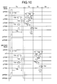
- Fig. 10 is a timing chart showing drive signals for reading out focal point detection signal from pixels exposed in a PD left-and-right bisected state.
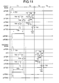
- Fig. 11 is a timing chart showing drive signals for reading out focal point detection signal from pixels exposed in a PD upper-and-lower bisected state.
- a signal line is selected every one horizontal row, and moved successively to the next row.
- movement shown in Figs. 9 through 11 is carried out, and drive signals shown in figures are output.
- the scanning is repeated over entire image field in vertical direction.
- select movement is returned to the top row after a vertical returning period has elapsed.
- Figs. 9 through 11 only shows drive signals in the first and the second rows.
- a period T1 is a period when all effective pixels are driven at the same time.
- the same drive signals are output in all rows.
- the period T2 is a period for reading out the first row
- the period T3 is a period for reading out the second row
- the period T4 is a period for reading out the third row
- the drive signal shown in the figure is output only to the selected row. The same holds for Figs. 10 and 11 explained later.
- ⁇ PDR is made high, so that the PD reset transistor 46 becomes on.
- unnecessary electric charge stored in all effective pixels in the pinned photodiodes 31 through 34 is discharged to the electric power supply VDD.
- the pinned photodiodes 31 through 34 are reset.
- the pinned photodiodes 31 through 34 in all effective pixels start exposure at the time the period T11 is finished.
- photoelectric conversion of incident light is performed in the area of the pinned photodiodes 31 through 34 as described above.
- ⁇ TGA is made high, so that the first and the second transfer transistors 37, 38 become on. All electric charge stored in the connected pinned photodiodes 31 through 34 and spaces between them in all effective pixels are transferred to the first and the second electric charge storage portions 35, 36 separately.
- the period T15 (the period from the time ⁇ PDR is made low to the time ⁇ TGA is made on) shown in Fig. 9 becomes exposure time. Exposure time T15 is the same period and the same timing for all effective pixels. Accordingly, all effective pixels can obtain imaging information without making mistakes in the timing.
- ⁇ S in the first row is made high, so that the selection transistor 45 becomes on. Accordingly, pixels in the first row are selected, and signals from the pixels in the first row are output to the vertical signal line 25.
- the second row is red out.
- the drive signal is the same as the first row.
- the periods T26 through T29 in Fig. 9 are corresponding to the periods T16 through T19.
- ⁇ PDR may be always high after completion of reading out (after ⁇ S is off).
- each pixel makes ⁇ PDB1, ⁇ PDB2 high, and combines four pinned photodiodes 31 through 34 in the period from the start of the period T11 to the end of the period T14, image signal can be output as usual.
- gate electrodes 67, 68 disposed along the division lines B-B', D-D' transmits incident light, using efficiency of the incident light enhances and sensitivity can be improved.
- an electronic shutter capable of making exposure timing of all pixels the same is possible. There is no doubt that the movement of a rolling shutter for resetting every row is also possible.
- This movement is carried out when desired row of pixels standing in a line in the left-and-right direction are used as a focal point detection line sensor to obtain focal point detection signal.
- a left-half signal in the present embodiment, the signal photoelectrically converted from the area between pinned photodiodes 31 and 33 is added
- a right-half signal in the present embodiment, the signal photoelectrically converted from the area between pinned photodiodes 32 and 34 is added
- the signal of all pixels red out in this manner is temporally stored in the memory 7 shown in Fig.
- focal point detection processing upon carrying out focal point detection processing at the focal point calculator, signals regarding only desired row of pixels are selectively used from the memory 7.
- focal point detection signal is obtained by reading out all pixels, pixels other than desired row of pixels may be thinned out and not necessary to be red out.
- ⁇ PDR is made to be high, so that PD reset transistor 46 becomes on, and ⁇ PDB1 and ⁇ PDB2 are made to be high, so that it becomes PD undivided state.
- unnecessary electric charge stored in pinned photodiodes 31 through 34 of all effective pixels is discharged to the power supply VDD.
- the pinned photodiodes 31 through 34 are reset.
- the pinned photodiodes 31 through 34 of all effective pixels starts exposure at the end of the period T31.
- photoelectric conversion of the incident light is carried out even on the area between the pinned photodiodes 31 through 34 as described above.
- ⁇ PDB1 is made to be low after termination of the period T31, even after terminating the period T31 ⁇ PDB2 is kept high until termination of the period T34. Accordingly, in the period after termination of the period T31 until termination of the period T34 all effective pixels become the PD left-and-right bisected state and the pinned photodiodes 31 through 34 of each pixel as a whole become substantially equivalent to a left-and-right bisected (bisected to a left portion and a right portion) photoelectric converter portion. In this period, movements according to the period T32 through T34 explained below are carried out.
- ⁇ FDR is made to be high, so that the FD reset transistor 44 becomes on.
- ⁇ TGB and ⁇ TGC are made to be high, so that the third and the fourth transfer transistor 41, 42 become on at the same time.
- the period T34 (the period from making ⁇ PDR low to making ⁇ TGA on) shown in Fig. 10 is the exposure period.
- the exposure period T35 is the same period and the same timing for all effective pixels. Accordingly, all effective pixels can obtain focal point detection information without shifting timing.
- the movements of the period so far (period T1) is the same as the movements for obtaining image signal explained with reference to Fig. 9 except exposure is carried out in the PD left-and-right bisected state.
- ⁇ S of the first row is made to be high, so that the select transistor 45 becomes on. Accordingly, pixels of the first row are selected, and signals are output from pixels of the first row to the vertical signal line 25.
- ⁇ FDR of the first row is made to be high, and the FD reset transistor 44 is on. With this movement, FD40 is reset.
- the output from the amplifying transistor 43 of the first row upon resetting the FD40 is stored in the CDS circuit 27 through the vertical signal line 25.
- ⁇ TGC is made to be high, so that the fourth transfer transistor 42 becomes on. Accordingly, electric charge stored in the second electric charge storage portion 36 is transferred to the FD40. Potential amplified in accordance with the amount of electric charge is transferred to the CDS circuit 27 through the vertical signal line 25. In the CDS circuit 27, the difference from the previously stored output upon resetting is output as a pupil signal output of the other of the left-and-right direction of the pixels in the first row. These pupil signal output of the other of the left-and-right direction of the pixels in the first row is output by the drive signal of the horizontal scanning circuit 22 through the horizontal signal line 28 and the output amplifier 29.
- pupil signal output of one of the left-and-right direction and pupil signal output of the other of the left-and-right direction of the pixels in the first row can be obtained.
- ⁇ PDR After completion of readout (after ⁇ S is off) ⁇ PDR may be always high.
- ⁇ PDR may be always high.
- each pixel becomes in the PD left-and-right bisected state by making ⁇ PDB1 low and making ⁇ PDB2 high in the period from the completion of the period T31 to the completion of the period T34, pupil signal output of one side in the left-and-right direction and pupil signal output of the other side in the left-and-right direction of each pixel can be obtained.
- gate electrodes 67, 68 disposed along the division lines B-B', D-D' transmit incident light, using efficiency of the incident light increases, and sensitivity of the focal point detection signal can be increased.
- an electronic shutter upon obtaining focal point detection signal, an electronic shutter whose exposure timing is the same over entire effective pixels can be available.
- This movement is carried out when desired column of pixels standing in a line in the upper-and-lower direction are used as a focal point detection line sensor to obtain focal point detection signal.
- an upper-half signal in the present embodiment, the signal photoelectrically converted from the area between pinned photodiodes 31 and 32 is added
- a lower-half signal in the present embodiment, the signal photoelectrically converted from the area between pinned photodiodes 33 and 34 is added
- the signal of all pixels red out in this manner is temporally stored in the memory 7 shown in Fig.
- focal point detection signal is obtained by reading out all pixels, pixels other than desired column of pixels are not necessary to be red out, or may be thinned out.
- the movement shown in Fig. 11 is basically similar to the afore-mentioned movement shown in Fig. 10 .
- the point of difference is that ⁇ PDB1 is interchanged with ⁇ PDB2.
- ⁇ PDB1 is on in the period from the start of the period T31 to the end of the period T34, and ⁇ PDB2 is on only in the period T31.
- focal point detection signal (pupil signal output of one side in the left-and-right direction and pupil signal output of the other side in the left-and-right direction) for detecting phase shift in the left-and-right direction can be obtained from any desired pixel line standing in line left-and-right direction.
- focal point detection signal for detecting phase shift in the left-and-right direction
- focal point detection signal (pupil signal output of one side in the upper-and-lower direction and pupil signal output of the other side in the upper-and-lower direction) for detecting phase shift in the upper-and-lower direction can be obtained from any desired pixel line standing in line upper-and-lower direction.
- the aforementioned solid-state imaging device 3 does not cause an effect something like a defect pixel, but is able to freely change whether which pixel functions as a pixel having a photoelectric converter portion bisected in which direction, so that it becomes possible to obtain an advantage that accuracy of focal point detection can be increased.
- a pupil division phase difference detection method in order to detect focal point at the center, upper part, or lower part of the image frame, it is said to be necessary to dispose left-and-right bisected photodiodes in the vertical direction (upper-and-lower direction) in a line sensor shape, and in order to detect focal point at the center, left part, or right part of the image frame, it is said to be necessary to dispose upper-and-lower bisected photodiodes in the horizontal direction (left-and-right direction) in a line sensor shape.
- the aforementioned solid-state imaging device 3 can carry out focal point detection in the horizontal direction (left-and-right direction) as well as in the vertical direction (upper-and-lower direction) despite of the same pixel configuration.
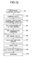
- Step S1 When a release button in the operating portion 9a is half-pressed (Step S1), the microprocessor 9 in the electronic camera 1 drives the imaging controller 4 corresponding to the half-press operation.
- the imaging controller 4 reads out imaging signal for confirming object from all pixels or given pixels by a given well-known method, and stores in the memory 7. In this case, when all pixels are to be red out, for example, the same movements shown in Fig. 9 are carried out.
- the image processor confirms object by using image confirming technique from the signal (Step S2). For example, in a face confirming mode, a face as an object is confirmed.
- the image processor 13 picks up central coordinates and a longitudinal direction of the object (Step S3).
- the microprocessor 9 sets coordinates of pixel line (position and longitudinal direction) corresponding to a line sensor for auto focus optimum for precision detection of focusing state to the object on the basis of the center coordinates and longitudinal direction picked up in step S3 (Step S4).
- Microprocessor 9 sets shooting condition (aperture stop, focusing state, shutter speed, and the like) for focal point detection on the basis of confirmation results in step S2 (Step S5).
- the microprocessor 9 successively moves the lens controller 2a to become the conditions such as aperture stop set by the step S5, and drives the imaging controller 4 to become shutter speed condition set by the step S5 and pixel line coordinates set by the step S4, and reads out auto focus signal to store the memory 7 (Step S6).
- the pixel line set in the step S4 is a pixel line standing in line of left-and-right direction
- image signal for auto focus is red out by the movements shown in Fig. 10 .
- the pixel line set in the step S4 is a pixel line standing in line of upper-and-lower direction
- image signal for auto focus is red out by the movements shown in Fig. 11 .
- the microprocessor 9 picks up signals of each pixel in the pixel line of coordinates set in the step S4 among signals of all pixels stored in the memory 7 obtained in the step S6, makes the focal point calculator 10 calculate in accordance with the pupil division phase difference detection method on the basis of these signals to obtain an amount of defocus (Step S7).
- the microprocessor 9 makes the lens controller 2a adjust the image-taking lens 2 to come to focus state in accordance with the amount of defocus calculated in step S7.
- the microprocessor 9 successively set shooting condition (aperture stop, shutter speed, and the like) for shooting.
- the microprocessor 9 makes the lens controller 2a set the aperture stop an the like to become the condition set in the step S9, and in synchronization with a full-press of the release button in the operating portion 9a drives the imaging controller 4 with the shutter time condition, and the like set in the step S9, so that shooting is carried out by reading out image signal (Step S10).
- image signal is red out by the aforementioned movement shown in Fig. 9 .
- the image signal is stored in the memory 7 by the imaging controller 4.
- the microprocessor 9 if required, performs required processing in the image processor 13 or the image compressor 12 on the basis of an instruction of the operating portion 9a, and makes the recorder output the processed signal to store in the recording medium 11a.
- CMOS type image sensor various kinds of pixel structure have been known.
- the present invention can apply to those image sensors.
- the present invention can apply to various image sensors other than the CMOS type image sensor.
- connection/separation transistors 51 through 54 are MOS transistors, those may be, for example, junction-field-effect-transistors (J-FET).
Landscapes
- Engineering & Computer Science (AREA)
- Multimedia (AREA)
- Signal Processing (AREA)
- Solid State Image Pick-Up Elements (AREA)
- Transforming Light Signals Into Electric Signals (AREA)
Abstract
Description
- The present invention relates to a solid-state imaging device and an imaging apparatus using the solid-state imaging device.
- Recently, an imaging apparatus such as a video camera and an electronic still camera has widely spread. In each of these cameras, a solid-state imaging device such as a CCD type and an amplification type is used. In such a solid-state imaging device, a plurality of pixels having a photoelectric converter portion for generating a signal charge in accordance with an amount of incident light are formed in a grid shape.
- In an amplification type solid-state imaging device, a signal charge generated and accumulated by the photoelectric converter portion in a pixel is led to an amplifying portion, and a signal amplified by the amplifying portion is output from the pixel.
- In an amplification type solid-state imaging device, there is proposed, for example, a solid-state imaging device using a junction-field-effect-transistor in the amplifying portion in Japanese Patent Application Laid-Open Nos.
11-177076 2004-335882 2004-111590 - In the conventional solid-state imaging devices disclosed in the above-described patent documents, a photoelectric converter portion, an amplifying portion, and a charge-storing portion for temporally storing the charge between them are disposed in each pixel. Moreover, in the conventional solid-state imaging devices, after exposing all pixels at the same time, the signal charge generated in each photoelectric converter portion is transferred to each charge-storing portion at the same time over all pixels and temporally stored, and the signal charge is successively converted into pixel signal with a prescribed readout timing. Accordingly, it becomes possible to prevent image deformation caused by difference in exposure time of respective pixels between lines upon carrying out electronic shutter movement, which is a so-called rolling shutter.
- In an imaging apparatus such as a camera, in order to realize automatic focusing control, it is necessary to detect a focusing state of an image-taking lens. Previously, a focal point detector was provided separately from a solid-state imaging device. However, in this case, cost increased and the apparatus became large by just the amount of the focal point detecting device and the focal point detecting optical system.
- Accordingly, there has been proposed a solid-state imaging device configured to be used as a focal point detector with using a so-called pupil division phase difference detection method (sometimes called as a pupil division method or a phase difference method) as a focal point detection method (for example, Japanese Patent Application Laid-Open No.
2003-244712 - In the solid-state imaging device disclosed in Japanese Patent Application Laid-Open No.
2003-244712 - In the solid-state imaging device disclosed in Japanese Patent Application Laid-Open No.
2003-244712 - In the solid-state imaging device disclosed in Japanese Patent Application Laid-Open No.
2003-244712 - However, in the solid-state imaging device disclosed in Japanese Patent Application Laid-Open No.
2003-244712 - The present invention is made in view of the above-described problems and has an object to provide a solid-state imaging device having a degree of freedom capable of changing which of the pixels functions as a pixel having a photoelectric converter portion bisected in which direction without causing the similar state of a defect pixel, and capable of enhancing detection accuracy of focus adjusting state, and an imaging apparatus using thereof.
- According to a first aspect of the present invention, there is provided a solid-state imaging device for photoelectrically converting an object image formed by an image-taking lens comprising: a plurality of pixels disposed two-dimensionally; at least a portion of pixels among the plurality of pixels including four photoelectric converter portions each of which exists in one of four areas divided by a first direction dividing line and a second direction dividing line crossing with each other in plan view and carries out photoelectric conversion and a mode setting member capable of selectively setting in each of a first through a third modes in accordance with a control signal. In the solid-state imaging device, the first mode is a mode that signals from two photoelectric converter portions locating in one side of the first direction dividing line among the four photoelectric converter portions are added, and signals from two photoelectric converter portions locating in the other side of the first direction dividing line among the four photoelectric converter portions are added, and both of the added signals are obtained independently. The second mode is a mode that signals from two photoelectric converter portions locating in one side of the second direction dividing line among the four photoelectric converter portions are added, and signals from two photoelectric converter portions locating in the other side of the second direction dividing line among the four photoelectric converter portions are added, and both of the added signals are obtained independently. The third mode is a mode that signals from the four photoelectric converter portions are added.
- According to a second aspect of the present invention, there is provided a solid-state imaging device for photoelectrically converting an object image formed by an image-taking lens comprising: a plurality of pixels disposed two-dimensionally; at least a portion of pixels among the plurality of pixels including four photoelectric converter portions each of which exists in one of four areas divided by a first direction dividing line and a second direction dividing line crossing with each other in plan view and carries out photoelectric conversion and a mode setting member capable of selectively setting in each of a first through a third modes in accordance with a control signal. In the solid-state imaging device, the first mode is a mode that two photoelectric converter portions locating in one side of the first direction dividing line among the four photoelectric converter portions are electrically connected, and two photoelectric converter portions locating in the other side of the first direction dividing line among the four photoelectric converter portions are electrically connected, and photoelectric converter portions located different side with respect to the first dividing line among the four photoelectric converter portions are electrically separated. The second mode is a mode that two photoelectric converter portions locating in one side of the second direction dividing line among the four photoelectric converter portions are electrically connected, and two photoelectric converter portions locating in the other side of the second direction dividing line among the four photoelectric converter portions are electrically connected, and photoelectric converter portions located different side with respect to the second dividing line among the four photoelectric converter portions are electrically separated. The third mode is a mode that two photoelectric converter portions locating in one side of the first direction dividing line among the four photoelectric converter portions, and two photoelectric converter portions locating in the other side of the first direction dividing line among the four photoelectric converter portions are electrically connected, and two photoelectric converter portions locating in one side of the second direction dividing line among the four photoelectric converter portions, and two photoelectric converter portions locating in the other side of the second direction dividing line among the four photoelectric converter portions are electrically connected.
- In the second aspect of the present invention, it is preferable that a space between each of the two photoelectric converter portions among the four photoelectric converter portions adjacent each other with respect to the first or the second dividing line has a photoelectric converter function when the two electric converter portions are electrically connected, and does not have a photoelectric converter function when the two electric converter portions are electrically separated.
- In the second aspect of the present invention, it is preferable that the mode setting member includes a first gate electrode disposed along the first dividing line and a second gate electrode disposed along the second dividing line.
- In the second aspect of the present invention, it is preferable that the first gate electrode constitutes a gate of an MOS transistor setting semiconductor areas of the two photoelectric converter portions locating one side of the second dividing line among the four photoelectric converter portions to be source or drain, and a gate of an MOS transistor setting semiconductor areas of the two photoelectric converter portions locating the other side of the second dividing line among the four photoelectric converter portions to be source or drain, and the second gate electrode constitutes a gate of an MOS transistor setting semiconductor areas of the two photoelectric converter portions locating one side of the first dividing line among the four photoelectric converter portions to be source or drain, and a gate of an MOS transistor setting semiconductor areas of the two photoelectric converter portions locating the other side of the first dividing line among the four photoelectric converter portions to be source or drain.
- In the second aspect of the present invention, it is preferable that the first and the second gate electrodes are constructed by a transparent material.
- In the second aspect of the present invention, it is preferable that the first and the second gate electrodes are constructed by polysilicon.
- In the second aspect of the present invention, it is preferable that the at least one portion of pixels include a first and a second electric charge storage portions for storing electric charge transferred from two respective photoelectric converter portions locating diagonally among the four photoelectric converter portions, an amplifier for outputting signal in accordance with an electric charge amount of a given portion, a first transfer gate for transferring electric charge from one side of photoelectric converter portion among the two photoelectric converter portions locating diagonally to the fist electric charge storage portion, a second transfer gate for transferring electric charge from the other side of photoelectric converter portion among the two photoelectric converter portions locating diagonally to the second electric charge storage portion, a third transfer gate for transferring electric charge from the first transfer gate to the given portion, and a fourth transfer gate for transferring electric charge from the second transfer gate to the given portion.
- In the second aspect of the present invention, it is preferable that the at least a portion of pixels includes an electric charge discharging gate for discharging electric charge from at least one photoelectric converter portion of the four photoelectric converter portions.
- In the second aspect of the present invention, it is preferable that a micro-lens for leading light to the four photoelectric converter portions is provided to each of at least a portion of pixels with one-to-one correspondence.
- According to a third aspect of the present invention, there is provided an imaging apparatus including the solid-state imaging device according to a first aspect or a second aspect, and a signal processor for outputting detection signal indicating focusing state of the image-taking lens on the basis of signals obtained in the first mode or the second mode from each of selected pixels among at least one portion of pixels.
- In the third aspect of the present invention, it is preferable that whether on which mode among the first and the second modes detection of focus adjusting state of the image-taking lens is based is determined in accordance with the object.
- In the third aspect of the present invention, it is preferable that a lens controller for controlling focus adjustment of the image-taking lens on the basis of the detection signal from the signal processor is included.
- According to the present invention, it becomes possible to provide a solid-state imaging device having a degree of freedom capable of changing whether which pixel is functioned as a pixel having a photoelectric converter portion bisected in which direction without causing the similar state of a defect pixel, and capable of thereby enhancing detection accuracy of focus adjusting state, and an imaging apparatus using thereof.
-
-
Fig. 1 is a block diagram showing an electronic camera according to an embodiment of the present invention. -
Fig. 2 is a circuit diagram showing broad configuration of a solid-state imaging device shown inFig. 1 . -
Fig. 3 is a circuit diagram showing a pixel shown inFig. 2 . -
Fig. 4 is a plan view typically showing the pixel shown inFig. 2 . -
Fig. 5 is a sectional view along A-A' line inFig. 4 showing a predetermined movement state. -
Fig. 6 is a sectional view along A-A' line inFig. 4 showing another movement state. -
Fig. 7 is a sectional view along B-B' line inFig. 4 . -
Fig. 8 is a sectional view along C-C' line inFig. 4 . -
Fig. 9 is a timing chart showing a movement state of the solid-state imaging device shown inFig. 1 . -
Fig. 10 is a timing chart showing another movement state of the solid-state imaging device shown inFig. 1 . -
Fig. 11 is a timing chart showing still another movement state of the solid-state imaging device shown inFig. 1 . -
Fig. 12 is a flow chart showing a movement example of the electric still camera shown inFig. 1 . - A solid-state imaging device and an imaging apparatus using the same according to the present invention are explained below with reference to accompanying drawings.
-
Fig. 1 is a block diagram showing anelectronic camera 1 as an imaging apparatus according to an embodiment of the present invention. Theelectronic camera 1 is equipped with an image-takinglens 2. The image-takinglens 2 is controlled by alens controller 2a upon focusing and stopping down of an aperture stop. An imaging surface of a solid-state imaging device 3 is disposed in the image side space of the image-takinglens 2. - The solid-
state imaging device 3 is driven by an instruction of animaging controller 4 and outputs a signal. The signal output from the solid-state imaging device 3 is either an imaging signal or a focal point detection signal. Either way a signal is processed by asignal processor 5 and an A/D converter 6, and stored temporarily in amemory 7. Thememory 7 is connected to a data bus 8. The data bus 8 is connected with thelens controller 2a, theimaging controller 4, amicroprocessor 9, a focal point calculator (detection processor) 10, arecorder 11, animage compressor 12, and animage processor 13. Themicroprocessor 9 is connected with an operatingportion 9a such as a release button. Therecorder 11 is removably connected with arecording medium 11a. Movement of theelectronic camera 1 is going to be explained later with reference toFig. 12 . -
Fig. 2 is a circuit diagram showing broad configuration of a solid-state imaging device 3 shown inFig. 1 . The solid-state imaging device 3 has a plurality ofpixels 20 formed in a grid shape and peripheral circuitry for outputting a signal from thepixel 20. InFig. 2 , the number of pixels is 16 that is four rows horizontally and four columns vertically. However, the present invention is not limited to this. Although dotted line denoted by 20 shows an outline of a pixel, specific configuration and circuitry of the pixel are explained later. - In the present embodiment, with the exception of dummy or optical black, which does not perform photoelectric conversion (in other words, in the area of so-called effective pixels), each
pixel 20 has the same circuitry and plane structure. Thepixel 20 outputs either an imaging signal or a focal point detection signal in accordance with a drive signal from peripheral circuitry. Moreover, the whole pixels can be reset their photoelectric converter portions at the same time, so that exposure time and timing thereof can be made the same. - Peripheral circuitry is composed of a
vertical scanning circuit 21, ahorizontal scanning circuit 22,drive signal lines vertical signal line 25 for receiving signals from pixels, a constant-current power supply 26 for connecting to thevertical signal line 25, a correlation double sampling circuit (CDS) 27, ahorizontal signal line 28 for receiving signal output from the correlationdouble sampling circuit 27, anoutput amplifier 29, and the like. - The
vertical scanning circuit 21 and thehorizontal scanning circuit 22 output a driving signal on the basis of an instruction from theimaging controller 4 of theelectronic camera 1. Each pixel receives the driving signal output from thevertical scanning circuit 21 through thedrive signal line 23, and is driven, and outputs the imaging signal or the focal point detection signal to thevertical signal line 25. Thevertical scanning circuit 21 outputs a plurality of drive signals. Accordingly, a plurality ofdrive signal lines 23 are there. This is explained later. - The signal output from the
pixel 20 is carried out predetermined noise reduction by the correlationdouble sampling circuit 27, and output in accordance with driving signal from thehorizontal scanning circuit 22 through thehorizontal signal line 28 and theoutput amplifier 29. -
Fig. 3 is a circuit diagram showing apixel 20 shown inFig. 2 . Thepixel 20 includes four pinnedphotodiodes 31 through 34 as four photoelectric converter portions for generating and storing electric charge, a first and a second electriccharge storage portions photodiodes second transfer transistors photodiodes charge storage portions fourth transfer transistors charge storage portions transistor 43 as an amplifying portion for outputting signal in accordance with the amount of electric charge ofFD 40, anFD reset transistor 44 as a first reset portion for discharging electric charge of the FD40, aselect transistor 45 as a select switch for outputting signal from thepixel 20 through the amplifyingtransistor 43, and aPD reset transistor 46 as a second reset portion (an electric charge discharging portion) for discharging electric charge (disused electric charge generated by the pinnedphotodiodes 31 through 34) from the pinnedphotodiode 31. - Moreover, the
pixel 20 includes a connection/separation transistor 51 for electrically connecting and separating pinnedphotodiodes separation transistor 52 for electrically connecting and separating pinnedphotodiodes separation transistor 53 for electrically connecting and separating pinnedphotodiodes separation transistor 54 for electrically connecting and separating pinnedphotodiodes - The first through
fourth transfer transistors transistor 43, FD resettransistor 44, theselect transistor 45, PD resettransistor 46, connection/separation transistors 51 through 54 are constructed by MOS transistors. In the present embodiment, these transistors except amplifyingtransistor 43 become on when the gate electrode is high, and off when the gate electrode is low. - Gate electrodes of connection/
separation transistors vertical scanning circuit 21 throughdrive signal line 23. Gate electrodes of connection/separation transistors vertical scanning circuit 21 throughdrive signal line 23. - In the present embodiment, when ϕPDB1 is high and (ϕPDB2 is low, connection/
separation transistors separation transistors photodiodes photodiodes photodiodes photodiodes photodiodes 31 through 34 as a whole become substantially equivalent to an upper-and-lower bisected (bisected into an upper portion and a lower portion) photoelectric converter portion. In the following explanation, this state is called as a PD upper-and-lower bisected state. - When (ϕPDB1 is low and ϕPDB2 is high, connection/
separation transistors separation transistors photodiodes photodiodes photodiodes photodiodes photodiodes 31 through 34 as a whole become substantially equivalent to a left-and-right bisected (bisected into a left portion and a right portion) photoelectric converter portion. In the following explanation, this state is called as a PD left-and-right bisected state. - When ϕPDB1 is high and (ϕPDB2 is high, connection/
separation transistors 51 through 54 become on, so that pinnedphotodiodes photodiodes photodiodes photodiodes photodiodes 31 through 34 as a whole become substantially equivalent to an undivided photoelectric converter portion. In the following explanation, this state is called as a PD undivided state. - In the present embodiment, the first and the second electric
charge storage portions photodiodes 31 through 34 is temporarily stored in the first and the second electriccharge storage portions charge storage portions - The
first transfer transistor 37 transfers electric charge from the pinnedphotodiode 32 to the first electriccharge storage portion 35. The place where the electric charge is generated differs under which state the exposure is took place such as the PD upper-and-lower bisected state, the PD left-and-right bisected state, or the PD undivided state. Thesecond transfer transistor 38 transfers electric charge from the pinnedphotodiode 33 to the second electriccharge storage portion 36. The place where the electric charge is generated also differs under which state the exposure is took place such as the PD upper-and-lower bisected state, the PD left-and-right bisected state, or the PD undivided state. - Gate electrodes of the first and the
second transfer transistors vertical scanning circuit 21 throughdrive signal line 23. The first and thesecond transfer transistors photodiodes charge storage portions second transfer transistor - On the other hand, the third and the
fourth transfer transistors third transfer transistor 41 is mutually connected every pixel row and drive signal ϕTGB is provided from thevertical scanning circuit 21 throughdrive signal line 23. Gate electrode of thefourth transfer transistor 41 is mutually connected every pixel row, and drive signal ϕTGC is provided from thevertical scanning circuit 21 throughdrive signal line 23. The third and thefourth transfer transistors charge storage portions - Gate electrode of the
select transistor 45 is mutually connected every pixel row, and drive signal ϕS is provided from thevertical scanning circuit 21 throughdrive signal line 23. Gate electrode of the FD resettransistor 44 is mutually connected every pixel row, and drive signal ϕFDR is provided from thevertical scanning circuit 21 throughdrive signal line 23. Gate electrode of the PD resettransistor 46 is mutually connected every pixel row, and drive signal ϕPDR is provided from thevertical scanning circuit 21 throughdrive signal line 23. - In the present embodiment, all of the effective pixels have the same structure, and these pixels can output either focal point detection signal or image signal. However, the present invention is not limited to this, and a focal point detection area may be provided to a given position of the solid-
state imaging device 3, and pixels for outputting focal point detection signal may be disposed in the area. - In
Fig. 3 , one terminal of pinnedphotodiodes 31 through 34, one terminal of electriccharge storage portions Figs. 5 through 8 explained later, they become electric potentials of P-well 62. -
Fig. 4 is a plan view typically showing the pixel shown inFig. 2 .Figs. 5 and 6 are sectional views along A-A' line inFig. 4 .Fig. 5 shows a state where the second gate electrode is low (in other words, ϕPDB2 is low), and the connection/separation transistor 51 is made to be off.Fig. 7 is a sectional view along B-B' line inFig. 4 .Fig. 8 is a sectional view along C-C' line inFig. 4 . InFigs. 5 through 8 , the micro-lens is omitted. InFigs. 4 through 8 , drive lines are omitted, except electrical connection of lines in thepixel 20. - For the sake of simplicity, mutually orthogonal X axis, Y axis, and Z axis are defined as shown in
Fig. 4 . The surface of thesubstrate 61 is regarded as parallel to the XY surface. In X direction, the arrow is called as +X direction, and the opposite direction is called as -X direction, and the same goes for the Y direction. In the present specification, X direction is the right-and-left direction, +X direction is the right side, -X direction is the left side, Y direction is the upper-and-lower direction, +Y direction is the upper side, and -Y direction is the lower side. - As shown in
Figs. 5 through 8 , a P-type well 62 is formed on an N-type silicon substrate 61. An N-typecharge storage layer 63 is formed on the P-type well 62, and by adding a P-typedepletion prevention layer 64 on the surface side of thecharge storage layer 63 pinnedphotodiodes 31 through 34 are composed. Here, although the construction of a pinned photodiode is adopted, the present invention is not limited to this, and the depletion prevention layer may be omitted. - As shown in
Fig. 4 , the four pinnedphotodiodes 31 through 34 are disposed in four areas divided by a division line B-B' in Y direction and a division line D-D' in X direction each crossing in a plane seen from Z direction. The pinnedphotodiode 31 is disposed in the upper left area, the pinnedphotodiode 32 is in the upper right area, the pinnedphotodiode 33 is in the lower left area, and the pinnedphotodiode 34 is in the lower right area among the four areas. These pinnedphotodiodes 31 through 34 are disposed near to the intersection of the division lines B-B' and D-D', and disposed rotationally symmetric around the intersection. As shown inFig. 4 , a micro-lens 65 for leading incident light to the pinnedphotodiodes 31 through 34 is disposed. The micro-lens is disposed such that the centerline thereof passes through the intersection of the division lines B-B' and D-D'. Accordingly, incident light led by the micro-lens 65 is divided at the pupil and led to each pinnedphotodiodes 31 through 34. In order to lower the shading effect, for example, the micro-lens may be disposed such that in a pixel located near the center of the effective pixel area the center of the micro-lens comes to the intersection of the division lines B-B' and D-D', on the other hand, in the periphery of the effective pixel area the center of the micro-lens comes to a shifted position from the intersection. - As shown in
Figs. 4 through 7 , thefirst gate electrode 67 is disposed along the division line B-B', and thesecond gate electrode 68 is disposed along the division line D-D'. Thesecond gate electrode 68 is formed on between the pinnedphotodiodes photodiodes silicon oxide layer 66. Accordingly, thesecond gate electrode 68 forms a gate of an MOS transistor (connection/separation transistor 51) composed of thecharge storage layer 63 of the pinnedphotodiode 31 and thecharge storage layer 63 of the pinnedphotodiode 32 as a source or a drain, and a gate of an MOS transistor (connection/separation transistor 52) composed of thecharge storage layer 63 of the pinnedphotodiode 33 and thecharge storage layer 63 of the pinnedphotodiode 34 as a source or a drain. The drive signal ϕPDB1 is provided to thesecond gate electrode 68 from a line (not shown). - Similarly, the
first gate electrode 67 is formed on between the pinnedphotodiodes photodiodes silicon oxide layer 66. Accordingly, thefirst gate electrode 67 forms a gate of an MOS transistor (connection/separation transistor 53) composed of thecharge storage layer 63 of the pinnedphotodiode 31 and thecharge storage layer 63 of the pinnedphotodiode 33 as a source or a drain, and a gate of an MOS transistor (connection/separation transistor 54) composed of thecharge storage layer 63 of the pinnedphotodiode 32 and thecharge storage layer 63 of the pinnedphotodiode 34 as a source or a drain. The drive signal ϕPDB2 is provided to thefirst gate electrode 68 from a line (not shown). - At the point where the first and the
second gate electrodes second gate electrode 68 passes over thegate electrode 67 through an insulation layer as shown inFig. 7 . - In the present embodiment, when the
second gate electrode 68 is low (ϕPDB2 is low), since an inversion layer does not generated in the channel area of the connection/separation transistor 51 as shown inFig. 5 , the connection/separation transistor 51 becomes off. On the other hand, when thesecond gate electrode 68 is high (ϕPDB2 is high), since aninversion layer 69 is generated in the channel area of the connection/separation transistor 51, the connection/separation transistor 51 becomes on. The similar can be applied to the other connection/separation transistors 52 through 54. - Although the connection/
separation transistors 51 through 54 become off when the voltage of the gate thereof is made to become zero potential (voltage of the substrate 1), they may be made to be on when the difference to the zero potential becomes large. Moreover, although the connection/separation transistors 51 through 54 become on when the voltage of the gate thereof is made to become zero potential (voltage of the substrate 1), they may be made to be off when negative voltage than the zero potential is applied. When the connection/separation transistors 51 through 54 are constructed to be off when the gate voltage is not applied, they become on when the positive voltage applied to the gate voltage, and when the connection/separation transistors 51 through 54 are constructed to be on when the gate voltage is not applied, they become off when the negative voltage is applied to the gate voltage. - In the present embodiment, the first and the
second gate electrodes second gate electrodes photodiodes 31 through 34 located under the first and thesecond gate electrodes separation transistor 51 is on as shown inFig. 6 , since aninversion layer 69 formed between the pinnedphotodiodes separation transistor 51 is off as shown inFig. 5 , since aninversion layer 69 is not formed, the area between the pinnedphotodiodes photodiodes 31 through 34. - The first and the
second gate electrodes - In the present invention, although it is disadvantageous in terms of using efficiency of the incident light, the first and the
second gate electrodes - As is understood from the above explanation, in the present embodiment, the first and the
second gate electrodes photodiodes photodiodes photodiodes photodiodes photodiodes 31 through 34 are added. - Even if pinned
photodiodes 31 through 34 are constructed to be completely electrically separated with each other, by suitably disposing charge storage portions and transfer switches so as to independently use or add signals red out from pinnedphotodiodes 31 through 34 in accordance with control signal, it becomes possible to realize the similar signal adding modes such as the PD left-and-right bisected state, the PD left-and-right bisected state, and the PD undivided state, so that the present invention may include such construction. However, when pinnedphotodiodes 31 through 34 can be separated or connected in accordance with the control signal as shown in the present embodiment, the number of external charge storage portions and transfer switches can be reduced and wiring can be simplified, so that it is much desirable. - Moreover, between the first and a second electric
charge storage portions photodiodes gate electrodes silicon oxide film 66. The first and asecond transfer transistors gate electrodes charge storage potions photodiodes - The
gate electrodes second transfer transistors photodiodes charge storage portions - The electric
charge storage portions type layers type well 62. Thegate electrodes second transfer transistor type layers charge storage portions gate electrodes type layers - When the
gate electrodes charge storage portions type well 62 and are filled with holes. Magnitude of a dark current is largely dependent on electron occupation probability of the interface state. Accordingly, dark currents of the electriccharge storage portions gate electrodes - In
Fig. 4 , FD40 is constructed as substantially one floating diffusion by electrically connecting two N-type areas wiring 77. Electric charge is transferred from either of the two electricalcharge storage portions -
Gate electrodes silicon oxide film 66 between the first and the second electriccharge storage portions fourth transfer transistors gate electrodes type layers charge storage portions - The
gate electrode 78 of thethird transfer transistor 41 and thegate electrode 79 of thefourth transfer transistor 42 are independently formed and supplied with independent drive signals ϕTGB and ϕTGC from thevertical scanning circuit 21. Accordingly, the third and thefourth transfer transistors fourth transfer transistors charge storage portions - Furthermore, as shown in
Fig. 8 , other than N-type diffusion layer 76, N-type diffusion layers 81 through 83 are formed along C-C' line inFig. 4 . The N-type layer 81 is connected to a power supply VDD by unillustrated wiring. Agate electrode 84 is formed on the N-type layers silicon oxide film 66. The amplifyingtransistor 43 is constructed as an MOS transistor making thegate electrode 84 as a gate, and the N-type layers gate electrode 84 is connected to the FD40 (N-type layers 75, 76) by thewiring 77. - A
gate electrode 85 is formed on a space between N-type layers silicon oxide film 66. Theselect transistor 45 is constructed as an MOS transistor making thegate electrode 85 as a gate, and N-type layers - A
gate electrode 86 is formed on a space between N-type layers silicon oxide film 66. The FD resettransistor 44 is constructed as an MOS transistor making thegate electrode 86 as a gate, and N-type layers - As shown in
Figs. 5 and 6 , N-type layer 87 is formed in P well 62. Agate electrode 88 is formed on a space between N-type layer 87 and the pinnedphotodiode 31 through a thinsilicon oxide film 66. PD resettransistor 46 is constructed as an MOS transistor making thegate electrode 88 as a gate, and N-type layer 87 and the electriccharge storage layer 63 of the pinnedphotodiode 31 as a source or a drain. Drive signal ϕPDR is supplied to thegate electrode 88 by an unillustrated wiring. - A second reset portion (here, PD reset transistor 46) discharges unnecessary electric charge in the pinned
photodiodes 31 through 34. In the unnecessary electric charge, there are reset electric charge upon operating electric shutter and overflowed electric charge upon receiving strong incident light. In either case, unnecessary electric charge may be transferred to the FD40 and discharged by the first reset portion (here, FD reset transistor 44). When performing in this manner, the second reset portion is not necessary to be disposed. - Moreover, thick
silicon oxide film 70 is formed on the circumference of the pinnedphotodiodes 31 through 34 and each N-type layer, and each element is separated. - Then, an example of timing for reading out signals from the solid-
state imaging device 3 is explained with reference toFigs. 9 through 11 . -
Fig. 9 is a timing chart showing drive signals (in other words, drive signals for reading out signals from pixels exposed in a PD undivided state) for reading out imaging signal.Fig. 10 is a timing chart showing drive signals for reading out focal point detection signal from pixels exposed in a PD left-and-right bisected state.Fig. 11 is a timing chart showing drive signals for reading out focal point detection signal from pixels exposed in a PD upper-and-lower bisected state. - As for vertical scanning, a signal line is selected every one horizontal row, and moved successively to the next row. In each selected row, movement shown in
Figs. 9 through 11 is carried out, and drive signals shown in figures are output. The scanning is repeated over entire image field in vertical direction. When the scanning has been completed at the bottom row, select movement is returned to the top row after a vertical returning period has elapsed.Figs. 9 through 11 only shows drive signals in the first and the second rows. - At first, an example of movement for reading out imaging signal is explained with reference to
Figs. 9 ,2 , and3 . In this movement, allpixels 20 basically become a PD undivided state upon exposure. In this movement, all pixels are exposed at the same time. - In
Fig. 9 , a period T1 is a period when all effective pixels are driven at the same time. In other words, regarding drive pulse in the period T1, the same drive signals are output in all rows. The period T2 is a period for reading out the first row, the period T3 is a period for reading out the second row, the period T4 is a period for reading out the third row, and the drive signal shown in the figure is output only to the selected row. The same holds forFigs. 10 and11 explained later. - At first, in the period from the starting point of period T11 to the ending point of period T14, all effective pixels become the PD undivided state by making ϕPDB1 and ϕPDB2 high. Accordingly, the pinned
photodiodes 31 through 34 as a whole become substantially equivalent to an undivided photoelectric converter. In this period, movements of the periods T11 through T14 explained later are carried out. - At first, in the period T11, ϕPDR is made high, so that the PD reset
transistor 46 becomes on. With this movement, unnecessary electric charge stored in all effective pixels in the pinnedphotodiodes 31 through 34 is discharged to the electric power supply VDD. In other words, the pinnedphotodiodes 31 through 34 are reset. The pinnedphotodiodes 31 through 34 in all effective pixels start exposure at the time the period T11 is finished. On this occasion, in the present embodiment, photoelectric conversion of incident light is performed in the area of the pinnedphotodiodes 31 through 34 as described above. - In the period T12, ϕFDR is made high, so that the FD reset
transistor 44 becomes on. At the same time, in the period T13, ϕTGB and ϕTGC are made high, so that the third and thefourth transfer transistors charge storage portions charge storage portions - In the period T14, ϕTGA is made high, so that the first and the
second transfer transistors photodiodes 31 through 34 and spaces between them in all effective pixels are transferred to the first and the second electriccharge storage portions second transfer transistors Fig. 9 becomes exposure time. Exposure time T15 is the same period and the same timing for all effective pixels. Accordingly, all effective pixels can obtain imaging information without making mistakes in the timing. - Then, in the period T16, ϕS in the first row is made high, so that the
selection transistor 45 becomes on. Accordingly, pixels in the first row are selected, and signals from the pixels in the first row are output to thevertical signal line 25. - At the same time, in the period T17, ϕFDR in the first row is made high, so that the FD reset
transistor 44 becomes on. With this movement, the FD40 is reset. At the end of the period T17, in other words, the period (period T18) from the time ϕFDR is made low to the time the period T19 starts, output of the amplifyingtransistor 43 of the first row upon resetting FD40 is stored in theCDS circuit 27 through thevertical signal line 25. - In the period T19, ϕTGB and ϕTGC are made high, so that the third and the
fourth transfer transistors charge storage portions CDS circuit 27 through thevertical signal line 25. In theCDS circuit 27, difference from the previously stored output upon reset is output as the image signal of the first row. Then, the image signal of the first row is output by the drive signal of thehorizontal scanning circuit 22 through thehorizontal signal line 28 and theoutput amplifier 29. - Likewise, in the period T3, the second row is red out. The drive signal is the same as the first row. The periods T26 through T29 in
Fig. 9 are corresponding to the periods T16 through T19. - Incidentally, ϕPDR may be always high after completion of reading out (after ϕS is off).
- As understood from the explanation above, since each pixel makes ϕPDB1, ϕPDB2 high, and combines four pinned
photodiodes 31 through 34 in the period from the start of the period T11 to the end of the period T14, image signal can be output as usual. Moreover, sincegate electrodes - Moreover, since all pixels have the same configuration in the above-described solid-
state imaging device 3, it becomes unnecessary to make correction on a portion of pixels upon reading out image signal. When a pixel for detecting focal point and a pixel for imaging are different configuration, it becomes necessary to make correction on a portion of pixels upon reading out image signal. - An example of movement for reading out focal point detection signal exposed in a PD left-and-right bisected state is explained with reference to
Figs. 10 ,2 , and3 . In this movement, allpixels 20 basically become in a PD left-and-right bisected state upon exposure. In this movement, all pixels are exposed at the same time. - This movement is carried out when desired row of pixels standing in a line in the left-and-right direction are used as a focal point detection line sensor to obtain focal point detection signal. In an example of movement shown in
Fig. 10 , a left-half signal (in the present embodiment, the signal photoelectrically converted from the area between pinnedphotodiodes photodiodes memory 7 shown inFig. 1 , and then upon carrying out focal point detection processing at the focal point calculator, signals regarding only desired row of pixels are selectively used from thememory 7. In the example of movement shown inFig. 10 , although focal point detection signal is obtained by reading out all pixels, pixels other than desired row of pixels may be thinned out and not necessary to be red out. - At first, in the period T31, ϕPDR is made to be high, so that PD reset
transistor 46 becomes on, and ϕPDB1 and ϕPDB2 are made to be high, so that it becomes PD undivided state. With this movement, unnecessary electric charge stored in pinnedphotodiodes 31 through 34 of all effective pixels is discharged to the power supply VDD. In other words, the pinnedphotodiodes 31 through 34 are reset. The pinnedphotodiodes 31 through 34 of all effective pixels starts exposure at the end of the period T31. At this time, in the present embodiment, photoelectric conversion of the incident light is carried out even on the area between the pinnedphotodiodes 31 through 34 as described above. - Although ϕPDB1 is made to be low after termination of the period T31, even after terminating the period T31 ϕPDB2 is kept high until termination of the period T34. Accordingly, in the period after termination of the period T31 until termination of the period T34 all effective pixels become the PD left-and-right bisected state and the pinned
photodiodes 31 through 34 of each pixel as a whole become substantially equivalent to a left-and-right bisected (bisected to a left portion and a right portion) photoelectric converter portion. In this period, movements according to the period T32 through T34 explained below are carried out. - In the period T32, ϕFDR is made to be high, so that the FD reset
transistor 44 becomes on. At the same time, in the period T33, ϕTGB and ϕTGC are made to be high, so that the third and thefourth transfer transistor charge storage portions charge storage portions - In the period T34, ϕTGA is made to be high, so that the first and the
second transfer transistors photodiodes charge storage portion 35 through thefirst transfer transistor 37. On the other hand, electric charge stored in the pinnedphotodiodes charge storage portion 36 through thesecond transfer transistor 38. Here, the period T35 (the period from making ϕPDR low to making ϕTGA on) shown inFig. 10 is the exposure period. The exposure period T35 is the same period and the same timing for all effective pixels. Accordingly, all effective pixels can obtain focal point detection information without shifting timing. The movements of the period so far (period T1) is the same as the movements for obtaining image signal explained with reference toFig. 9 except exposure is carried out in the PD left-and-right bisected state. - Then, in the period T36, ϕS of the first row is made to be high, so that the
select transistor 45 becomes on. Accordingly, pixels of the first row are selected, and signals are output from pixels of the first row to thevertical signal line 25. - At the same time, in the period T37, ϕFDR of the first row is made to be high, and the FD reset
transistor 44 is on. With this movement, FD40 is reset. At the end of the period T37, in other words, during the period (period T38) after ϕFDR becomes low to the start of the period T39, the output from the amplifyingtransistor 43 of the first row upon resetting the FD40 is stored in theCDS circuit 27 through thevertical signal line 25. - In the period T39, ϕTGB is made to be high, so that the
third transfer transistor 41 becomes on. Accordingly, electric charge stored in the first electriccharge storage portion 35 is transferred to the FD40. Potential amplified in accordance with the amount of electric charge is transferred to theCDS circuit 27 through thevertical signal line 25. In theCDS circuit 27, the difference from the previously stored output upon resetting FD40 is output as a pupil signal output of one of the left-and-right direction of the pixels in the first row. These pupil signal output of one of the left-and-right direction of the pixels in the first row is output by the drive signal of thehorizontal scanning circuit 22 through thehorizontal signal line 28 and theoutput amplifier 29. - Then, in the period T40, ϕFDR of the first row is made to be high, and the FD reset
transistor 44 is on. With this movement, FD40 is reset. At the end of the period T40, in other words, during the period (period T41) after ϕFDR becomes low to the start of the period T42, the output from the amplifyingtransistor 43 of the first row upon resetting the FD40 is stored in theCDS circuit 27 through thevertical signal line 25. - In the period T42, ϕTGC is made to be high, so that the
fourth transfer transistor 42 becomes on. Accordingly, electric charge stored in the second electriccharge storage portion 36 is transferred to the FD40. Potential amplified in accordance with the amount of electric charge is transferred to theCDS circuit 27 through thevertical signal line 25. In theCDS circuit 27, the difference from the previously stored output upon resetting is output as a pupil signal output of the other of the left-and-right direction of the pixels in the first row. These pupil signal output of the other of the left-and-right direction of the pixels in the first row is output by the drive signal of thehorizontal scanning circuit 22 through thehorizontal signal line 28 and theoutput amplifier 29. - With these movement, pupil signal output of one of the left-and-right direction and pupil signal output of the other of the left-and-right direction of the pixels in the first row can be obtained.
- Similarly the following rows are red out. Drive signal is the same as the first row. The periods T46 through T52 in
Fig. 10 correspond to the periods T36 through T42. - After completion of readout (after ϕS is off) ϕPDR may be always high. As is understood from the above explanation, since each pixel becomes in the PD left-and-right bisected state by making ϕPDB1 low and making ϕPDB2 high in the period from the completion of the period T31 to the completion of the period T34, pupil signal output of one side in the left-and-right direction and pupil signal output of the other side in the left-and-right direction of each pixel can be obtained. Moreover, since
gate electrodes - Then, an example of movement for reading out focal point detection signal exposed in a PD upper-and-lower bisected state is explained with reference to
Figs. 11 ,2 , and3 . In this movement, allpixels 20 basically become in a PD upper-and-lower bisected state upon exposure. In this movement, all pixels are exposed at the same time. - This movement is carried out when desired column of pixels standing in a line in the upper-and-lower direction are used as a focal point detection line sensor to obtain focal point detection signal. In an example of movement shown in
Fig. 11 , an upper-half signal (in the present embodiment, the signal photoelectrically converted from the area between pinnedphotodiodes photodiodes memory 7 shown inFig. 1 , and then upon carrying out focal point detection processing at the focal point calculator, signals regarding only desired column of pixels are selectively used from thememory 7. In the example of movement shown inFig. 11 , although focal point detection signal is obtained by reading out all pixels, pixels other than desired column of pixels are not necessary to be red out, or may be thinned out. - The movement shown in
Fig. 11 is basically similar to the afore-mentioned movement shown inFig. 10 . The point of difference is that ϕPDB1 is interchanged with ϕPDB2. In other words, in the movement shown inFig. 11 , ϕPDB1 is on in the period from the start of the period T31 to the end of the period T34, and ϕPDB2 is on only in the period T31. - Accordingly, in the movement shown in
Fig. 11 , since each pixel becomes in the PD upper-and-lower bisected state during the period from at the end of the period T31 to the end of the period T34 by making ϕPDB1 high and ϕPDB2 low, pupil signal output of one side in the upper-and-lower direction and pupil signal output of the other side in the upper-and-lower direction of each pixel can be obtained. Moreover, sincegate electrodes - As is understood from the above-described explanation, in the aforementioned solid-
state imaging device 3, by carrying our movements shown inFig. 10 , focal point detection signal (pupil signal output of one side in the left-and-right direction and pupil signal output of the other side in the left-and-right direction) for detecting phase shift in the left-and-right direction can be obtained from any desired pixel line standing in line left-and-right direction. Moreover, in the aforementioned solid-state imaging device 3, by carrying out movements shown inFig. 11 , focal point detection signal (pupil signal output of one side in the upper-and-lower direction and pupil signal output of the other side in the upper-and-lower direction) for detecting phase shift in the upper-and-lower direction can be obtained from any desired pixel line standing in line upper-and-lower direction. - Accordingly, the aforementioned solid-
state imaging device 3 does not cause an effect something like a defect pixel, but is able to freely change whether which pixel functions as a pixel having a photoelectric converter portion bisected in which direction, so that it becomes possible to obtain an advantage that accuracy of focal point detection can be increased. - In a pupil division phase difference detection method, in order to detect focal point at the center, upper part, or lower part of the image frame, it is said to be necessary to dispose left-and-right bisected photodiodes in the vertical direction (upper-and-lower direction) in a line sensor shape, and in order to detect focal point at the center, left part, or right part of the image frame, it is said to be necessary to dispose upper-and-lower bisected photodiodes in the horizontal direction (left-and-right direction) in a line sensor shape. The aforementioned solid-
state imaging device 3 can carry out focal point detection in the horizontal direction (left-and-right direction) as well as in the vertical direction (upper-and-lower direction) despite of the same pixel configuration. - Then, an example of movement of an
electronic camera 1 according to the present embodiment is explained with reference toFigs. 1 and12 . - When a release button in the operating
portion 9a is half-pressed (Step S1), themicroprocessor 9 in theelectronic camera 1 drives theimaging controller 4 corresponding to the half-press operation. In order to confirm an object, theimaging controller 4 reads out imaging signal for confirming object from all pixels or given pixels by a given well-known method, and stores in thememory 7. In this case, when all pixels are to be red out, for example, the same movements shown inFig. 9 are carried out. The image processor confirms object by using image confirming technique from the signal (Step S2). For example, in a face confirming mode, a face as an object is confirmed. Theimage processor 13 picks up central coordinates and a longitudinal direction of the object (Step S3). - Then, the
microprocessor 9 sets coordinates of pixel line (position and longitudinal direction) corresponding to a line sensor for auto focus optimum for precision detection of focusing state to the object on the basis of the center coordinates and longitudinal direction picked up in step S3 (Step S4).Microprocessor 9 sets shooting condition (aperture stop, focusing state, shutter speed, and the like) for focal point detection on the basis of confirmation results in step S2 (Step S5). - The
microprocessor 9 successively moves thelens controller 2a to become the conditions such as aperture stop set by the step S5, and drives theimaging controller 4 to become shutter speed condition set by the step S5 and pixel line coordinates set by the step S4, and reads out auto focus signal to store the memory 7 (Step S6). At this time, when the pixel line set in the step S4 is a pixel line standing in line of left-and-right direction, image signal for auto focus is red out by the movements shown inFig. 10 . On the other hand, when the pixel line set in the step S4 is a pixel line standing in line of upper-and-lower direction, image signal for auto focus is red out by the movements shown inFig. 11 . - Then, the
microprocessor 9 picks up signals of each pixel in the pixel line of coordinates set in the step S4 among signals of all pixels stored in thememory 7 obtained in the step S6, makes thefocal point calculator 10 calculate in accordance with the pupil division phase difference detection method on the basis of these signals to obtain an amount of defocus (Step S7). - Then, the
microprocessor 9 makes thelens controller 2a adjust the image-takinglens 2 to come to focus state in accordance with the amount of defocus calculated in step S7. Themicroprocessor 9 successively set shooting condition (aperture stop, shutter speed, and the like) for shooting. - Then, the
microprocessor 9 makes thelens controller 2a set the aperture stop an the like to become the condition set in the step S9, and in synchronization with a full-press of the release button in the operatingportion 9a drives theimaging controller 4 with the shutter time condition, and the like set in the step S9, so that shooting is carried out by reading out image signal (Step S10). At this time, image signal is red out by the aforementioned movement shown inFig. 9 . The image signal is stored in thememory 7 by theimaging controller 4. - After that, the
microprocessor 9, if required, performs required processing in theimage processor 13 or theimage compressor 12 on the basis of an instruction of the operatingportion 9a, and makes the recorder output the processed signal to store in therecording medium 11a. - In the
electronic camera 1 according to the present embodiment, since auto focus is carried out by detecting focusing state on the basis of the signal of the pixel line at the optimized position in accordance with the object, it becomes possible to carry out auto focus with high precision. - Although an embodiment of the present invention is explained above, the present invention is not limited to the embodiment.
- For example, in a CMOS type image sensor, various kinds of pixel structure have been known. The present invention can apply to those image sensors. Moreover, the present invention can apply to various image sensors other than the CMOS type image sensor.
- Furthermore, in the present embodiment, although the connection/
separation transistors 51 through 54 are MOS transistors, those may be, for example, junction-field-effect-transistors (J-FET).
Claims (13)
- A solid-state imaging device for photoelectrically converting an object image formed by an image-taking lens comprising:a plurality of pixels disposed two-dimensionally;at least a portion of pixels among the plurality of pixels including four photoelectric converter portions each of which exists in one of four areas divided by a first direction dividing line and a second direction dividing line crossing with each other in plan view and carries out photoelectric conversion and a mode setting member capable of selectively setting in each of a first through a third modes in accordance with a control signal;the first mode being a mode in that signals from two photoelectric converter portions located in one side of the first direction dividing line among the four photoelectric converter portions are added, and signals from two photoelectric converter portions located in the other side of the first direction dividing line among the four photoelectric converter portions are added, and both of the added signals are obtained independently;the second mode being a mode in that signals from two photoelectric converter portions located in one side of the second direction dividing line among the four photoelectric converter portions are added, and signals from two photoelectric converter portions located in the other side of the second direction dividing line among the four photoelectric converter portions are added, and both of the added signals are obtained independently; andthe third mode being a mode in that signals from the four photoelectric converter portions are added.
- A solid-state imaging device for photoelectrically converting an object image formed by an image-taking lens comprising:a plurality of pixels disposed two-dimensionally;at least a portion of pixels among the plurality of pixels including four photoelectric converter portions each of which exists in one of four areas divided by a first direction dividing line and a second direction dividing line crossing with each other in plan view and carries out photoelectric conversion and a mode setting member capable of selectively setting in each of a first through a third modes in accordance with a control signal;the first mode being a mode in that two photoelectric converter portions located in one side of the first direction dividing line among the four photoelectric converter portions are electrically connected, and two photoelectric converter portions located in the other side of the first direction dividing line among the four photoelectric converter portions are electrically connected, and photoelectric converter portions located on a different side with respect to the first dividing line among the four photoelectric converter portions are electrically separated;the second mode being a mode in that two photoelectric converter portions located in one side of the second direction dividing line among the four photoelectric converter portions are electrically connected, and two photoelectric converter portions located in the other side of the second direction dividing line among the four photoelectric converter portions are electrically connected, and photoelectric converter portions located on a different side with respect to the second dividing line among the four photoelectric converter portions are electrically separated;the third mode being a mode in that two photoelectric converter portions located in one side of the first direction dividing line among the four photoelectric converter portions, and two photoelectric converter portions located in the other side of the first direction dividing line among the four photoelectric converter portions are electrically connected, and two photoelectric converter portions located in one side of the second direction dividing line among the four photoelectric converter portions, and two photoelectric converter portions located in the other side of the second direction dividing line among the four photoelectric converter portions are electrically connected.
- The solid-state imaging device according to claim 2, wherein a space between each of the two photoelectric converter portions among the four photoelectric converter portions adjacent each other with respect to the first or the second dividing line has a photoelectric converter function when the two electric converter portions are electrically connected, and does not have a photoelectric converter function when the two electric converter portions are electrically separated.
- The solid-state imaging device according to claim 3, wherein the mode setting member includes a first gate electrode disposed along the first dividing line and a second gate electrode disposed along the second dividing line.
- The solid-state imaging device according to claim 4, wherein the first gate electrode constitutes a gate of an MOS transistor setting semiconductor areas of the two photoelectric converter portions located on one side of the second dividing line among the four photoelectric converter portions to be source or drain, and a gate of an MOS transistor setting semiconductor areas of the two photoelectric converter portions located on the other side of the second dividing line among the four photoelectric converter portions to be source or drain, and
the second gate electrode constitutes a gate of an MOS transistor setting semiconductor areas of the two photoelectric converter portions located on one side of the first dividing line among the four photoelectric converter portions to be source or drain, and a gate of an MOS transistor setting semiconductor areas of the two photoelectric converter portions located on the other side of the first dividing line among the four photoelectric converter portions to be source or drain. - The solid-state imaging device according to claim 4, wherein the first and the second gate electrodes are constructed by a transparent material.
- The solid-state imaging device according to claim 5, wherein the first and the second gate electrodes are constructed by polysilicon.
- The solid-state imaging device according to claim 2, wherein the at least one portion of pixels include
a first and a second electric charge storage portions for storing electric charge transferred from two respective photoelectric converter portions located diagonally among the four photoelectric converter portions,
an amplifier for outputting signal in accordance with an electric charge amount of a given portion,
a first transfer gate for transferring electric charge from one side of photoelectric converter portion among the two photoelectric converter portions located diagonally to the fist electric charge storage portion,
a second transfer gate for transferring electric charge from the other side of photoelectric converter portion among the two photoelectric converter portions located diagonally to the second electric charge storage portion,
a third transfer gate for transferring electric charge from the first transfer gate to the given portion, and
a fourth transfer gate for transferring electric charge from the second transfer gate to the given portion. - The solid-state imaging device according to any one of claims 1 through 8, wherein the at least a portion of pixels includes an electric charge discharging gate for discharging electric charge from at least one photoelectric converter portion of the four photoelectric converter portions.
- The solid-state imaging device according to claim 1, wherein a micro-lens for leading light to the four photoelectric converter portions is provided to each of at least a portion of pixels with one-to-one correspondence.
- An imaging apparatus including the solid-state imaging device according to any one of claims 1 through 10, and a signal processor for outputting detection signal indicating focusing state of the image-taking lens on the basis of signals obtained in the first mode or the second mode from each of selected pixels among at least one portion of pixels
- The imaging apparatus according to claim 11, wherein it is determined in accordance with the object on which mode among the first and the second modes detection of focus adjusting state of the image-taking lens is based.
- The imaging apparatus according to claim 11, wherein a lens controller for controlling focus adjustment of the image-taking lens on the basis of the detection signal from the signal processor is included.
Applications Claiming Priority (2)
| Application Number | Priority Date | Filing Date | Title |
|---|---|---|---|
| JP2006155496A JP4835270B2 (en) | 2006-06-03 | 2006-06-03 | Solid-state imaging device and imaging apparatus using the same |
| PCT/JP2007/061251 WO2007142171A1 (en) | 2006-06-03 | 2007-05-29 | Solid-state imaging element and imaging device using the same |
Publications (3)
| Publication Number | Publication Date |
|---|---|
| EP2037672A1 true EP2037672A1 (en) | 2009-03-18 |
| EP2037672A4 EP2037672A4 (en) | 2010-07-28 |
| EP2037672B1 EP2037672B1 (en) | 2014-08-06 |
Family
ID=38801422
Family Applications (1)
| Application Number | Title | Priority Date | Filing Date |
|---|---|---|---|
| EP07744636.7A Ceased EP2037672B1 (en) | 2006-06-03 | 2007-05-29 | Solid-state imaging element and imaging device using the same |
Country Status (5)
| Country | Link |
|---|---|
| US (1) | US8159580B2 (en) |
| EP (1) | EP2037672B1 (en) |
| JP (1) | JP4835270B2 (en) |
| CN (1) | CN101461230B (en) |
| WO (1) | WO2007142171A1 (en) |
Cited By (8)
| Publication number | Priority date | Publication date | Assignee | Title |
|---|---|---|---|---|
| WO2009133944A1 (en) * | 2008-05-01 | 2009-11-05 | Canon Kabushiki Kaisha | Solid-state imaging apparatus |
| EP2107610A3 (en) * | 2008-04-03 | 2011-06-08 | Sony Corporation | Solid state imaging device, driving method of the solid state imaging device, and electronic equipment |
| EP2320460A4 (en) * | 2008-08-11 | 2011-10-19 | Honda Motor Co Ltd | PIXEL, PIXEL FORMING METHOD, IMAGE PRODUCTION DEVICE, AND IMAGE FORMING METHOD |
| GB2488234A (en) * | 2011-02-17 | 2012-08-22 | Canon Kk | Recording Captured Image Signals Along With Identification (e.g. Array Position) of the Capturing Element |
| FR2979485A1 (en) * | 2011-08-26 | 2013-03-01 | E2V Semiconductors | PIXEL REGROUPING IMAGE SENSOR |
| WO2013070280A1 (en) * | 2011-11-08 | 2013-05-16 | Aptina Imaging Corporation | Image sensor pixels with juncti0n gate photodiodes |
| EP2958317A1 (en) * | 2014-06-18 | 2015-12-23 | Canon Kabushiki Kaisha | Image pickup apparatus and method for controlling the same |
| US10896923B2 (en) | 2015-09-18 | 2021-01-19 | Semiconductor Energy Laboratory Co., Ltd. | Method of operating an imaging device with global shutter system |
Families Citing this family (39)
| Publication number | Priority date | Publication date | Assignee | Title |
|---|---|---|---|---|
| US7755121B2 (en) | 2007-08-23 | 2010-07-13 | Aptina Imaging Corp. | Imagers, apparatuses and systems utilizing pixels with improved optical resolution and methods of operating the same |
| US7495228B1 (en) * | 2008-03-31 | 2009-02-24 | General Electric Company | Dual function detector device |
| JP5461343B2 (en) * | 2010-08-24 | 2014-04-02 | 富士フイルム株式会社 | Imaging device and imaging apparatus |
| JP2012105023A (en) | 2010-11-09 | 2012-05-31 | Canon Inc | Image processing apparatus, image pickup device, and image processing method |
| JP5456644B2 (en) * | 2010-11-17 | 2014-04-02 | 本田技研工業株式会社 | Light receiving element and control method |
| JP5627438B2 (en) | 2010-12-14 | 2014-11-19 | キヤノン株式会社 | IMAGING DEVICE, ITS CONTROL METHOD, PROGRAM, AND STORAGE MEDIUM |
| JP5778931B2 (en) | 2011-01-25 | 2015-09-16 | キヤノン株式会社 | Imaging apparatus and control method thereof |
| JP5856376B2 (en) | 2011-01-27 | 2016-02-09 | キヤノン株式会社 | Imaging apparatus and control method thereof |
| JP5954964B2 (en) * | 2011-02-18 | 2016-07-20 | キヤノン株式会社 | Imaging apparatus and control method thereof |
| JP6041495B2 (en) * | 2011-03-24 | 2016-12-07 | キヤノン株式会社 | Imaging apparatus and defective pixel determination method |
| JP6039165B2 (en) * | 2011-08-11 | 2016-12-07 | キヤノン株式会社 | Imaging device and imaging apparatus |
| US20140191290A1 (en) * | 2011-08-24 | 2014-07-10 | Sharp Kabushiki Kaisha | Solid-state imaging element |
| JP5850680B2 (en) * | 2011-09-09 | 2016-02-03 | キヤノン株式会社 | Imaging apparatus and control method thereof |
| JP5967944B2 (en) * | 2012-01-18 | 2016-08-10 | キヤノン株式会社 | Solid-state imaging device and camera |
| JP6172888B2 (en) * | 2012-01-18 | 2017-08-02 | キヤノン株式会社 | Imaging apparatus and imaging system |
| JP5955000B2 (en) * | 2012-01-25 | 2016-07-20 | キヤノン株式会社 | Solid-state imaging device, distance detection device including the solid-state imaging device, and camera |
| JP2013172210A (en) | 2012-02-17 | 2013-09-02 | Canon Inc | Imaging device |
| WO2014097899A1 (en) * | 2012-12-21 | 2014-06-26 | 富士フイルム株式会社 | Solid-state image pickup device |
| JP5886781B2 (en) * | 2013-03-26 | 2016-03-16 | キヤノン株式会社 | FOCUS DETECTION DEVICE, FOCUS DETECTION METHOD AND PROGRAM, AND IMAGING DEVICE |
| JP6239855B2 (en) * | 2013-05-08 | 2017-11-29 | キヤノン株式会社 | Focus adjustment apparatus, focus adjustment method and program, and imaging apparatus |
| JP2015164284A (en) * | 2014-01-28 | 2015-09-10 | キヤノン株式会社 | Solid-state image sensor, movement information acquisition apparatus and imaging apparatus |
| JP6484513B2 (en) * | 2014-10-08 | 2019-03-13 | 株式会社テクノロジーハブ | Image sensor |
| JP6438290B2 (en) * | 2014-12-12 | 2018-12-12 | キヤノン株式会社 | Imaging apparatus and control method thereof |
| JP6650668B2 (en) | 2014-12-16 | 2020-02-19 | キヤノン株式会社 | Solid-state imaging device |
| JP6442362B2 (en) | 2015-05-29 | 2018-12-19 | キヤノン株式会社 | Image pickup apparatus and image pickup element control method |
| JP6676317B2 (en) | 2015-09-11 | 2020-04-08 | キヤノン株式会社 | Imaging device and imaging system |
| JP2017108281A (en) * | 2015-12-09 | 2017-06-15 | 株式会社ニコン | Imaging device and imaging apparatus |
| JP6736329B2 (en) * | 2016-03-31 | 2020-08-05 | キヤノン株式会社 | Image sensor |
| JP6748477B2 (en) | 2016-04-22 | 2020-09-02 | キヤノン株式会社 | Imaging device, control method thereof, program, and storage medium |
| JP6678505B2 (en) | 2016-04-22 | 2020-04-08 | キヤノン株式会社 | Imaging device, control method therefor, program, and storage medium |
| JP6678504B2 (en) | 2016-04-22 | 2020-04-08 | キヤノン株式会社 | Imaging device, control method therefor, program, and storage medium |
| JP7005125B2 (en) * | 2016-04-22 | 2022-01-21 | キヤノン株式会社 | Image sensor, image sensor, and method for manufacturing the image sensor |
| JP6741549B2 (en) | 2016-10-14 | 2020-08-19 | キヤノン株式会社 | Imaging device and control method thereof |
| JP7277106B2 (en) | 2018-10-25 | 2023-05-18 | ソニーグループ株式会社 | Solid-state imaging device and imaging device |
| JP7329318B2 (en) | 2018-10-25 | 2023-08-18 | ソニーグループ株式会社 | Solid-state imaging device and imaging device |
| JP7283511B2 (en) * | 2019-10-31 | 2023-05-30 | 株式会社ニコン | Imaging device and camera |
| KR102908808B1 (en) * | 2020-03-27 | 2026-01-07 | 에스케이하이닉스 주식회사 | Image sensing device |
| JP2021061618A (en) * | 2020-12-15 | 2021-04-15 | 株式会社ニコン | Imaging device and imaging apparatus |
| WO2022201835A1 (en) * | 2021-03-24 | 2022-09-29 | ソニーセミコンダクタソリューションズ株式会社 | Imaging element, and imaging device |
Family Cites Families (16)
| Publication number | Priority date | Publication date | Assignee | Title |
|---|---|---|---|---|
| US4410804A (en) * | 1981-07-13 | 1983-10-18 | Honeywell Inc. | Two dimensional image panel with range measurement capability |
| JP3874135B2 (en) | 1997-12-05 | 2007-01-31 | 株式会社ニコン | Solid-state image sensor |
| JP3524391B2 (en) * | 1998-08-05 | 2004-05-10 | キヤノン株式会社 | Imaging device and imaging system using the same |
| US6956605B1 (en) * | 1998-08-05 | 2005-10-18 | Canon Kabushiki Kaisha | Image pickup apparatus |
| US6710804B1 (en) * | 2000-01-18 | 2004-03-23 | Eastman Kodak Company | CMOS active pixel image sensor with extended dynamic range and sensitivity |
| WO2002043366A2 (en) * | 2000-11-27 | 2002-05-30 | Vision Sciences Inc. | Programmable resolution cmos image sensor |
| JP4500434B2 (en) * | 2000-11-28 | 2010-07-14 | キヤノン株式会社 | Imaging apparatus, imaging system, and imaging method |
| JP2002217399A (en) * | 2001-01-22 | 2002-08-02 | Fuji Photo Film Co Ltd | Charge reading method and solid-state imaging device |
| JP4027113B2 (en) | 2002-02-19 | 2007-12-26 | キヤノン株式会社 | Imaging apparatus and system |
| JP4403687B2 (en) | 2002-09-18 | 2010-01-27 | ソニー株式会社 | Solid-state imaging device and drive control method thereof |
| JP4300872B2 (en) * | 2003-05-09 | 2009-07-22 | 株式会社ニコン | Amplification type solid-state image sensor |
| JP4371797B2 (en) * | 2003-12-12 | 2009-11-25 | コニカミノルタホールディングス株式会社 | Solid-state imaging device |
| JP4502278B2 (en) | 2004-02-27 | 2010-07-14 | 国立大学法人東北大学 | Solid-state imaging device, line sensor, optical sensor, and operation method of solid-state imaging device |
| CN1993832B (en) * | 2004-07-20 | 2010-08-18 | 富士通微电子株式会社 | CMOS imaging element |
| US20060071290A1 (en) * | 2004-09-27 | 2006-04-06 | Rhodes Howard E | Photogate stack with nitride insulating cap over conductive layer |
| US7812299B2 (en) | 2005-07-22 | 2010-10-12 | Nikon Corporation | Image sensor having two-dimensionally arrayed pixels, focus detecting device using the sensor, and imaging system including the sensor |
-
2006
- 2006-06-03 JP JP2006155496A patent/JP4835270B2/en not_active Expired - Fee Related
-
2007
- 2007-05-29 WO PCT/JP2007/061251 patent/WO2007142171A1/en not_active Ceased
- 2007-05-29 EP EP07744636.7A patent/EP2037672B1/en not_active Ceased
- 2007-05-29 CN CN2007800206267A patent/CN101461230B/en not_active Expired - Fee Related
-
2008
- 2008-12-02 US US12/326,884 patent/US8159580B2/en not_active Expired - Fee Related
Cited By (19)
| Publication number | Priority date | Publication date | Assignee | Title |
|---|---|---|---|---|
| EP2107610A3 (en) * | 2008-04-03 | 2011-06-08 | Sony Corporation | Solid state imaging device, driving method of the solid state imaging device, and electronic equipment |
| US8934036B2 (en) | 2008-04-03 | 2015-01-13 | Sony Corporation | Solid state imaging device, driving method of the solid state imaging device and electronic equipment |
| US8284282B2 (en) | 2008-04-03 | 2012-10-09 | Sony Corporation | Solid state imaging device, driving method of the solid state imaging device, and electronic equipment |
| US8570410B2 (en) | 2008-04-03 | 2013-10-29 | Sony Corporation | Solid state imaging device, driving method of the solid state imaging device, and electronic equipment |
| WO2009133944A1 (en) * | 2008-05-01 | 2009-11-05 | Canon Kabushiki Kaisha | Solid-state imaging apparatus |
| EP2320460A4 (en) * | 2008-08-11 | 2011-10-19 | Honda Motor Co Ltd | PIXEL, PIXEL FORMING METHOD, IMAGE PRODUCTION DEVICE, AND IMAGE FORMING METHOD |
| GB2488234B (en) * | 2011-02-17 | 2013-06-12 | Canon Kk | Image capture apparatus and image signal processing apparatus |
| GB2488234A (en) * | 2011-02-17 | 2012-08-22 | Canon Kk | Recording Captured Image Signals Along With Identification (e.g. Array Position) of the Capturing Element |
| DE102012202386B4 (en) * | 2011-02-17 | 2017-02-09 | Canon Kabushiki Kaisha | PICTURE RECORDING DEVICE, PICTURE SIGNAL PROCESSING DEVICE, AND PICTURE PROCESSING OF PICTURE RECORDING DEVICE |
| US9800861B2 (en) | 2011-02-17 | 2017-10-24 | Canon Kabushiki Kaisha | Image capture apparatus and image signal processing apparatus |
| WO2013029885A1 (en) * | 2011-08-26 | 2013-03-07 | E2V Semiconductors | Pixel-grouping image sensor |
| FR2979485A1 (en) * | 2011-08-26 | 2013-03-01 | E2V Semiconductors | PIXEL REGROUPING IMAGE SENSOR |
| US9185319B2 (en) | 2011-08-26 | 2015-11-10 | E2V Semiconductors | Pixel-grouping image sensor |
| WO2013070280A1 (en) * | 2011-11-08 | 2013-05-16 | Aptina Imaging Corporation | Image sensor pixels with juncti0n gate photodiodes |
| US8710420B2 (en) | 2011-11-08 | 2014-04-29 | Aptina Imaging Corporation | Image sensor pixels with junction gate photodiodes |
| EP2958317A1 (en) * | 2014-06-18 | 2015-12-23 | Canon Kabushiki Kaisha | Image pickup apparatus and method for controlling the same |
| US9602741B2 (en) | 2014-06-18 | 2017-03-21 | Canon Kabushiki Kaisha | Image pickup apparatus and method for controlling image pickup apparatus |
| US10896923B2 (en) | 2015-09-18 | 2021-01-19 | Semiconductor Energy Laboratory Co., Ltd. | Method of operating an imaging device with global shutter system |
| US10917597B2 (en) | 2015-09-18 | 2021-02-09 | Semiconductor Energy Laboratory Co., Ltd. | Imaging device, module, and electronic device comprising a pixel including transistors using back gate electrical connections |
Also Published As
| Publication number | Publication date |
|---|---|
| WO2007142171A1 (en) | 2007-12-13 |
| CN101461230A (en) | 2009-06-17 |
| JP2007325139A (en) | 2007-12-13 |
| US8159580B2 (en) | 2012-04-17 |
| JP4835270B2 (en) | 2011-12-14 |
| CN101461230B (en) | 2011-02-23 |
| EP2037672B1 (en) | 2014-08-06 |
| US20090086063A1 (en) | 2009-04-02 |
| EP2037672A4 (en) | 2010-07-28 |
Similar Documents
| Publication | Publication Date | Title |
|---|---|---|
| EP2037672B1 (en) | Solid-state imaging element and imaging device using the same | |
| US8319874B2 (en) | Connection/separation element in photoelectric converter portion, solid-state imaging device, and imaging apparatus | |
| JP6127869B2 (en) | Solid-state imaging device, driving method thereof, and electronic apparatus | |
| US9030589B2 (en) | Image sensor and image sensing apparatus | |
| US9024363B2 (en) | Photoelectric conversion apparatus and imaging system using the photoelectric conversion apparatus | |
| JP4710660B2 (en) | Solid-state imaging device and electronic camera using the same | |
| EP1681851A1 (en) | Solid state image pickup device, camera, and driving method of solid state image pickup device | |
| US20120033120A1 (en) | Solid-state imaging device and electronic camera | |
| JP5045012B2 (en) | Solid-state imaging device and imaging apparatus using the same | |
| JP7005125B2 (en) | Image sensor, image sensor, and method for manufacturing the image sensor | |
| US10021316B2 (en) | Photoelectric conversion device having a plurality of photoelectric conversion units and a plurality of charge holding units, and imaging system | |
| US10455140B2 (en) | Focus detection device and imaging system | |
| JP4839990B2 (en) | Solid-state imaging device and imaging apparatus using the same | |
| JP5413481B2 (en) | Photoelectric conversion unit connection / separation structure, solid-state imaging device, and imaging apparatus | |
| US8913167B2 (en) | Image pickup apparatus and method of driving the same | |
| JP5750918B2 (en) | Solid-state imaging device and imaging apparatus using the same | |
| JP2005109370A (en) | Solid-state imaging device | |
| JP6676317B2 (en) | Imaging device and imaging system | |
| CN117256159B (en) | Solid-state imaging device and camera equipment |
Legal Events
| Date | Code | Title | Description |
|---|---|---|---|
| PUAI | Public reference made under article 153(3) epc to a published international application that has entered the european phase |
Free format text: ORIGINAL CODE: 0009012 |
|
| 17P | Request for examination filed |
Effective date: 20081229 |
|
| AK | Designated contracting states |
Kind code of ref document: A1 Designated state(s): AT BE BG CH CY CZ DE DK EE ES FI FR GB GR HU IE IS IT LI LT LU LV MC MT NL PL PT RO SE SI SK TR |
|
| AX | Request for extension of the european patent |
Extension state: AL BA HR MK RS |
|
| DAX | Request for extension of the european patent (deleted) | ||
| RBV | Designated contracting states (corrected) |
Designated state(s): DE FR GB IT |
|
| A4 | Supplementary search report drawn up and despatched |
Effective date: 20100629 |
|
| RAP1 | Party data changed (applicant data changed or rights of an application transferred) |
Owner name: NIKON CORPORATION |
|
| 17Q | First examination report despatched |
Effective date: 20110513 |
|
| REG | Reference to a national code |
Ref country code: DE Ref legal event code: R079 Ref document number: 602007037981 Country of ref document: DE Free format text: PREVIOUS MAIN CLASS: H04N0005335000 Ipc: H01L0027146000 |
|
| GRAP | Despatch of communication of intention to grant a patent |
Free format text: ORIGINAL CODE: EPIDOSNIGR1 |
|
| RIC1 | Information provided on ipc code assigned before grant |
Ipc: H04N 5/347 20110101ALI20140206BHEP Ipc: H04N 5/3745 20110101ALI20140206BHEP Ipc: H01L 27/146 20060101AFI20140206BHEP Ipc: H04N 5/232 20060101ALI20140206BHEP |
|
| INTG | Intention to grant announced |
Effective date: 20140220 |
|
| GRAS | Grant fee paid |
Free format text: ORIGINAL CODE: EPIDOSNIGR3 |
|
| GRAA | (expected) grant |
Free format text: ORIGINAL CODE: 0009210 |
|
| AK | Designated contracting states |
Kind code of ref document: B1 Designated state(s): DE FR GB IT |
|
| REG | Reference to a national code |
Ref country code: GB Ref legal event code: FG4D |
|
| REG | Reference to a national code |
Ref country code: DE Ref legal event code: R096 Ref document number: 602007037981 Country of ref document: DE Effective date: 20140918 |
|
| PG25 | Lapsed in a contracting state [announced via postgrant information from national office to epo] |
Ref country code: IT Free format text: LAPSE BECAUSE OF FAILURE TO SUBMIT A TRANSLATION OF THE DESCRIPTION OR TO PAY THE FEE WITHIN THE PRESCRIBED TIME-LIMIT Effective date: 20140806 |
|
| REG | Reference to a national code |
Ref country code: DE Ref legal event code: R097 Ref document number: 602007037981 Country of ref document: DE |
|
| PLBE | No opposition filed within time limit |
Free format text: ORIGINAL CODE: 0009261 |
|
| STAA | Information on the status of an ep patent application or granted ep patent |
Free format text: STATUS: NO OPPOSITION FILED WITHIN TIME LIMIT |
|
| 26N | No opposition filed |
Effective date: 20150507 |
|
| REG | Reference to a national code |
Ref country code: FR Ref legal event code: PLFP Year of fee payment: 10 |
|
| REG | Reference to a national code |
Ref country code: FR Ref legal event code: PLFP Year of fee payment: 11 |
|
| REG | Reference to a national code |
Ref country code: FR Ref legal event code: PLFP Year of fee payment: 12 |
|
| PGFP | Annual fee paid to national office [announced via postgrant information from national office to epo] |
Ref country code: DE Payment date: 20190514 Year of fee payment: 13 |
|
| PGFP | Annual fee paid to national office [announced via postgrant information from national office to epo] |
Ref country code: GB Payment date: 20190529 Year of fee payment: 13 |
|
| PGFP | Annual fee paid to national office [announced via postgrant information from national office to epo] |
Ref country code: FR Payment date: 20200414 Year of fee payment: 14 |
|
| REG | Reference to a national code |
Ref country code: DE Ref legal event code: R119 Ref document number: 602007037981 Country of ref document: DE |
|
| GBPC | Gb: european patent ceased through non-payment of renewal fee |
Effective date: 20200529 |
|
| PG25 | Lapsed in a contracting state [announced via postgrant information from national office to epo] |
Ref country code: GB Free format text: LAPSE BECAUSE OF NON-PAYMENT OF DUE FEES Effective date: 20200529 |
|
| PG25 | Lapsed in a contracting state [announced via postgrant information from national office to epo] |
Ref country code: DE Free format text: LAPSE BECAUSE OF NON-PAYMENT OF DUE FEES Effective date: 20201201 |
|
| PG25 | Lapsed in a contracting state [announced via postgrant information from national office to epo] |
Ref country code: FR Free format text: LAPSE BECAUSE OF NON-PAYMENT OF DUE FEES Effective date: 20210531 |