JP5778931B2 - Imaging apparatus and control method thereof - Google Patents
Imaging apparatus and control method thereof Download PDFInfo
- Publication number
- JP5778931B2 JP5778931B2 JP2011013370A JP2011013370A JP5778931B2 JP 5778931 B2 JP5778931 B2 JP 5778931B2 JP 2011013370 A JP2011013370 A JP 2011013370A JP 2011013370 A JP2011013370 A JP 2011013370A JP 5778931 B2 JP5778931 B2 JP 5778931B2
- Authority
- JP
- Japan
- Prior art keywords
- focus adjustment
- image
- photoelectric conversion
- area
- output
- Prior art date
- Legal status (The legal status is an assumption and is not a legal conclusion. Google has not performed a legal analysis and makes no representation as to the accuracy of the status listed.)
- Expired - Fee Related
Links
Images


Classifications
-
- G—PHYSICS
- G02—OPTICS
- G02B—OPTICAL ELEMENTS, SYSTEMS OR APPARATUS
- G02B7/00—Mountings, adjusting means, or light-tight connections, for optical elements
- G02B7/28—Systems for automatic generation of focusing signals
-
- H—ELECTRICITY
- H04—ELECTRIC COMMUNICATION TECHNIQUE
- H04N—PICTORIAL COMMUNICATION, e.g. TELEVISION
- H04N5/00—Details of television systems
- H04N5/76—Television signal recording
- H04N5/765—Interface circuits between an apparatus for recording and another apparatus
- H04N5/77—Interface circuits between an apparatus for recording and another apparatus between a recording apparatus and a television camera
- H04N5/772—Interface circuits between an apparatus for recording and another apparatus between a recording apparatus and a television camera the recording apparatus and the television camera being placed in the same enclosure
-
- G—PHYSICS
- G02—OPTICS
- G02B—OPTICAL ELEMENTS, SYSTEMS OR APPARATUS
- G02B7/00—Mountings, adjusting means, or light-tight connections, for optical elements
- G02B7/28—Systems for automatic generation of focusing signals
- G02B7/34—Systems for automatic generation of focusing signals using different areas in a pupil plane
-
- G—PHYSICS
- G03—PHOTOGRAPHY; CINEMATOGRAPHY; ANALOGOUS TECHNIQUES USING WAVES OTHER THAN OPTICAL WAVES; ELECTROGRAPHY; HOLOGRAPHY
- G03B—APPARATUS OR ARRANGEMENTS FOR TAKING PHOTOGRAPHS OR FOR PROJECTING OR VIEWING THEM; APPARATUS OR ARRANGEMENTS EMPLOYING ANALOGOUS TECHNIQUES USING WAVES OTHER THAN OPTICAL WAVES; ACCESSORIES THEREFOR
- G03B13/00—Viewfinders; Focusing aids for cameras; Means for focusing for cameras; Autofocus systems for cameras
- G03B13/32—Means for focusing
- G03B13/34—Power focusing
- G03B13/36—Autofocus systems
-
- H—ELECTRICITY
- H04—ELECTRIC COMMUNICATION TECHNIQUE
- H04N—PICTORIAL COMMUNICATION, e.g. TELEVISION
- H04N23/00—Cameras or camera modules comprising electronic image sensors; Control thereof
- H04N23/60—Control of cameras or camera modules
- H04N23/67—Focus control based on electronic image sensor signals
- H04N23/672—Focus control based on electronic image sensor signals based on the phase difference signals
-
- H—ELECTRICITY
- H04—ELECTRIC COMMUNICATION TECHNIQUE
- H04N—PICTORIAL COMMUNICATION, e.g. TELEVISION
- H04N23/00—Cameras or camera modules comprising electronic image sensors; Control thereof
- H04N23/60—Control of cameras or camera modules
- H04N23/67—Focus control based on electronic image sensor signals
- H04N23/673—Focus control based on electronic image sensor signals based on contrast or high frequency components of image signals, e.g. hill climbing method
-
- H—ELECTRICITY
- H04—ELECTRIC COMMUNICATION TECHNIQUE
- H04N—PICTORIAL COMMUNICATION, e.g. TELEVISION
- H04N23/00—Cameras or camera modules comprising electronic image sensors; Control thereof
- H04N23/60—Control of cameras or camera modules
- H04N23/67—Focus control based on electronic image sensor signals
- H04N23/675—Focus control based on electronic image sensor signals comprising setting of focusing regions
-
- H—ELECTRICITY
- H04—ELECTRIC COMMUNICATION TECHNIQUE
- H04N—PICTORIAL COMMUNICATION, e.g. TELEVISION
- H04N25/00—Circuitry of solid-state image sensors [SSIS]; Control thereof
- H04N25/70—SSIS architectures; Circuits associated therewith
- H04N25/703—SSIS architectures incorporating pixels for producing signals other than image signals
- H04N25/704—Pixels specially adapted for focusing, e.g. phase difference pixel sets
Landscapes
- Engineering & Computer Science (AREA)
- Multimedia (AREA)
- Signal Processing (AREA)
- Physics & Mathematics (AREA)
- General Physics & Mathematics (AREA)
- Optics & Photonics (AREA)
- Focusing (AREA)
- Studio Devices (AREA)
- Automatic Focus Adjustment (AREA)
Description
本発明は撮像装置及びその制御方法に関し、各画素から光学系の異なる瞳領域を通過した光束に基づく一対の信号を読み出すことが可能な撮像装置及びその制御方法に関する。 The present invention relates to an imaging apparatus and a control method thereof, and more particularly to an imaging apparatus capable of reading a pair of signals based on a light beam that has passed through different pupil regions of an optical system from each pixel and a control method thereof.
従来より、焦点検出機能と画像信号取得を1枚の撮像素子を用いて実現する技術が知られており、その一例として、焦点検出用の情報取得用画素を、画像信号取得のための画像取得用画素として兼用できるものが提案されている(例えば、特許文献1参照)。この技術によれば、情報取得用画素を水平、垂直方向に4分割し、画像取得時には4分割された領域の信号をすべて加算することで画像信号を得る。また、焦点調節時には、4分割された領域の内、水平または垂直方向の2領域の信号を加算することで、画素内を瞳分割し、位相差方式の焦点調節用信号として用いることができる。 Conventionally, a technique for realizing a focus detection function and image signal acquisition using one image sensor is known. As an example, information acquisition pixels for focus detection are used for image acquisition for image signal acquisition. A pixel that can also be used as a pixel is proposed (for example, see Patent Document 1). According to this technique, the information acquisition pixel is divided into four in the horizontal and vertical directions, and an image signal is obtained by adding all the signals of the four divided areas at the time of image acquisition. Further, at the time of focus adjustment, by adding signals of two regions in the horizontal or vertical direction among the four divided regions, the inside of the pixel can be divided into pupils and used as a phase difference type focus adjustment signal.
しかしながら、撮像素子の多画素化に伴い、予め定められた時間内により多くの画素信号を読み出すことが要求される一方で、撮像素子の出力レートの増加あるいは出力チャンネル数の増加などによるシステムへの負荷も大きくなってきている。たとえば、出力チャンネル数が増加することにより、あるいは、信号出力のレートが上がることにより、チャンネル間の信号遅延量の調整が複雑になるという問題があった。特に、1つの画素が複数の光電変換部によって構成され、瞳分割読み出し機能を持った撮像素子の場合は、信号の読み出し数が増えるため、さらにシステムへの負担は増加してしまう。 However, with the increase in the number of pixels of the image sensor, it is required to read out more pixel signals within a predetermined time. On the other hand, an increase in the output rate of the image sensor or an increase in the number of output channels is required. The load is also increasing. For example, there is a problem that adjustment of the signal delay amount between channels becomes complicated as the number of output channels increases or the rate of signal output increases. In particular, in the case of an imaging device in which one pixel is constituted by a plurality of photoelectric conversion units and has a pupil division readout function, the number of signal readouts increases, which further increases the burden on the system.
本発明は上記問題点を鑑みてなされたものであり、撮像素子内の任意の領域に焦点調節領域を設定可能にしつつ、撮像素子からの画像信号の読み出し時間を短縮することを目的とする。 The present invention has been made in view of the above problems, and an object of the present invention is to shorten the readout time of an image signal from an image sensor while making it possible to set a focus adjustment area in an arbitrary area within the image sensor.
上記目的を達成するために、本発明の撮像装置は、複数のマイクロレンズと、各マイクロレンズに対して構成された複数の光電変換部と、各光電変換部から出力された画像信号をそれぞれ記憶する記憶手段と、前記記憶手段に記憶された前記画像信号を非加算でそれぞれ出力するか、または前記各マイクロレンズに対応する複数の光電変換部毎に前記画像信号を加算して出力するかを切り替える制御手段とを有する撮像素子と、前記撮像素子における焦点調節を行う対象領域である焦点調節領域を決定する決定手段とを有し、前記制御手段は、各行の読み出し中に、前記焦点調節領域内の前記光電変換部から出力された前記画像信号を非加算でそれぞれ出力し、前記焦点調節領域外の前記光電変換部から出力された前記画像信号を加算して出力するように切り替え、更に、前記焦点調節領域内の前記光電変換部から出力された前記非加算の画像信号に基づいて、位相差方式の焦点調節制御を行う焦点調節手段と、前記撮像素子から出力された画像信号のうち、前記焦点調節領域内の前記非加算の画像信号を前記各マイクロレンズに対応する複数の光電変換部毎に加算すると共に、前記焦点調節領域外の前記加算した画像信号をそのまま出力する信号演算手段とを有し、前記決定手段は、前記信号演算手段から出力された画像信号の画像を用いて前記焦点調節領域を決定する。 To achieve the above object, an imaging apparatus of the present invention includes a plurality of microlenses, the plurality configured for each microlens and the photoelectric conversion unit, the images signals output from the respective photoelectric conversion portions, respectively a storage storing means, wherein either output the Kiga image signal before being stored in the non-additive in the storage means or said image signal addition to the each of the plurality of photoelectric conversion units corresponding to each microlens outputs an image pickup device and a control means for switching either the to, pre SL and a determination means for determining a focus control area is a target area for focusing in the image sensor, wherein, in each row of the read, the outputs respectively Kiga image signals before outputted from the photoelectric conversion unit of the focus adjustment area in the non-addition, the Kiga image signals before outputted from the photoelectric conversion portion outside the focusing area to the summing Out Switching manner to further the on the basis of the non-added image signals outputted from the photoelectric conversion unit of the focus adjustment area, and the focus adjusting means for performing focus adjustment control of the phase difference method, the output from the imaging device Among the image signals thus added, the non-added image signal in the focus adjustment area is added for each of the plurality of photoelectric conversion units corresponding to the microlenses, and the added image signal outside the focus adjustment area is added. and a signal operation unit for outputting it, said determining means that determine the focus control area using the image of the image signal output from the signal operation unit.
本発明によれば、撮像素子内の任意の領域に焦点調節領域を設定可能にしつつ、撮像素子からの画像信号の読み出し時間を短縮することができる。 ADVANTAGE OF THE INVENTION According to this invention, the readout time of the image signal from an image pick-up element can be shortened, enabling a focus adjustment area | region to be set to the arbitrary areas in an image pick-up element.
以下、添付図面を参照して本発明を実施するための最良の形態を詳細に説明する。 The best mode for carrying out the present invention will be described below in detail with reference to the accompanying drawings.
<第1の実施形態>
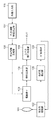
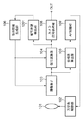
図1は、本発明の第1の実施形態における撮像装置の概略構成を示すブロック図である。図1において、101はフォーカスレンズを含み、更にはズームレンズ、絞りなどで構成される光学系、102は、後述するAF制御部109から出力される光学系駆動情報に応じて光学系101を制御信号により制御する光学系駆動部である。
<First Embodiment>
FIG. 1 is a block diagram illustrating a schematic configuration of an imaging apparatus according to the first embodiment of the present invention. In FIG. 1,
103は、被写体像を光電変換により電気信号に変換して、画像信号として出力する撮像素子であり、後述する指示情報生成部106から出力される指示情報に従って画像信号を読み出す。本第1の実施形態においては、後述するように、各画素は、光学系101の射出瞳の異なる領域を通過した光束をそれぞれ受光し、瞳分割された画像信号を出力する複数の光電変換部を有する。なお、撮像素子103の構成は、図2を参照して詳細に後述する。104は、撮像素子103から出力された画像信号に対して演算処理を施す信号演算部であり、後述するようにして、指示情報生成部106から出力される指示情報に従って画像信号に対して演算を施し、表示記録用の画像信号として出力する。108はカメラ信号処理部で、信号演算部104から得られた画像信号に対し、色変換、ホワイトバランス補正、ガンマ補正等の画像処理、解像度変換処理、画像圧縮処理等を行い、不図示の記録装置や表示装置に処理後の画像信号を出力する。
110は、ユーザからの指示を受ける外部入力部、107は、外部入力部110から送られてくる外部入力情報に応じて、焦点調節を行う対象領域である焦点調節領域を決定する焦点調節領域決定部である。焦点調節領域決定部107は、決定された焦点調節領域の情報(焦点調節領域情報)を指示情報生成部106へ渡す。106は、焦点調節領域情報を基に焦点調節領域内か焦点調節領域外かを示す指示情報を生成する指示情報生成部であり、指示情報は撮像素子103及び信号演算部104へと送られる。
110 is an external input unit that receives an instruction from the user, and 107 is a focus adjustment region determination that determines a focus adjustment region that is a target region for focus adjustment according to external input information sent from the
105は位相差算出部で、撮像素子103から出力される瞳分割された画像信号から位相差方式の焦点調節を行うための位相差評価値を算出する。109はAF制御部で、位相差算出部105で算出された位相差評価値を基に、光学系101のフォーカスレンズ位置を制御するための光学系駆動情報を算出する。すなわち、位相差算出部105及びAF制御部109により、公知の位相差方式の焦点調節制御が行われる。
A phase
次に、本第1の実施形態における撮像素子103の構成について、図2を参照して説明する。本第1の実施形態における撮像素子103は、XYアドレス型の走査方法を採る、例えばCMOSイメージセンサである。
Next, the configuration of the
図2(a)は、1つの画素203の概略を示した上面図であり、入射光を電荷に変換するフォトダイオードに代表される複数の光電変換部を含んでいる。ここでは、2つの光電変換部PD1、PD2を持つ例を示しており、光電変換部PD1、PD2に共通で1つのマイクロレンズ204を備える構造となっている。また、撮像素子103の他の画素についても、図示した位置関係に光電変換部PD1、PD2が存在するものとする。このように構成することにより、光電変換部PD1、PD2は、それぞれが光学系101の射出瞳の異なる領域を通過した光束を受光することになる。
FIG. 2A is a top view schematically showing one
図2(b)及び(c)は、撮像素子103の回路図を示し、図2(b)は、画素203を構成する一方の光電変換部に係る回路(以下、「半画素部」と呼ぶ。)211の回路図、図2(c)は画素203を含む全体構成を示している。なお、図2(b)に示す例では、光電変換部PD1を含む半画素部211を図示しているが、光電変換部PD2を含む半画素部も同様の構成を有している。また、図2(c)においては、説明を分かり易くするために3行×2列分の画素203(即ち、3行×4列分の半画素部211)を示しているが、実際には通常、数十万〜数千万の画素203が、所定のアスペクト比で2次元に配置されている。また、各画素203はR、G、Bいずれかの色相のカラーフィルタにより覆われていてもよく、例えば、R、G、Bのカラーフィルタがベイヤー配列に並べられるようにしてもよい。
2B and 2C are circuit diagrams of the
図2(b)において、206は光電変換部PD1で発生した電荷を一時的に蓄積しておく蓄積領域となるフローティングデフュージョン部(FD)である。205は光電変換部PD1で発生した電荷を転送パルスpTXによってFD206に転送する転送スイッチ、207はリセットパルスpRESによってFD206に蓄積された電荷を除去するリセットスイッチである。208はソースフォロアアンプとして機能する増幅MOSアンプ、302は、列を選択するための選択スイッチである。転送スイッチ205、リセットスイッチ207、選択スイッチ302のゲートは、図2(c)に示すように、行単位でそれぞれpTX、pRES、pSELを供給する信号線にそれぞれに接続され、垂直走査回路301によって選択走査される。また、リセットスイッチ207と増幅MOSアンプ208のドレインは電源ライン209と接続されている。
In FIG. 2B,
また、図2(c)において、304は増幅MOSアンプ208の負荷となる定電流源であり、半画素部211と定電流源304は信号出力線210を介して列AD変換回路305に列単位で接続される。FD206、増幅MOSアンプ208、及び定電流源304でフローティングディフュージョンアンプが構成され、選択スイッチ302で選択された画素の信号電荷が電圧に変換され、信号出力線210を経て、列AD変換回路305に出力される。
In FIG. 2C,
列AD変換回路305は、半画素部211から出力される電圧信号をデジタルコードに変換する回路である。一般的には電圧信号とランプ波形をコンパレータで比較し、ランプ波形出力の開始とともにカウンタを回すことで電圧信号とランプ波形が一致したときのカウンター値をデジタルコードとして変換する構成を持つ。306は列AD変換回路305でデジタルコードに変換された半画素部211の出力をデジタル信号として記憶するラインメモリである。タイミング制御回路307は指示情報生成部106から送られてくる指示情報に基づき、ラインメモリ306に記憶されているデジタル信号を画像信号として出力する。また、タイミング制御回路307は、各画素203の光電変換部PD1、PD2のデジタル信号を同時にラインメモリ306から読み出し、信号処理で加算して出力したり、光電変換部PD1、PD2のデジタル信号をそれぞれ出力することができる構成を持つ。
The column
次に、本第1の実施形態における焦点調節領域の決定方法及びその指示情報の生成手順について説明する。 Next, a method for determining a focus adjustment area and a procedure for generating instruction information thereof in the first embodiment will be described.
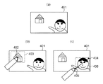
図3は、本第1の実施形態における焦点調節領域の指定方法を説明する図である。なお、焦点調節領域は、画像の中で、焦点を合わせる領域のことを指す。図3(a)において、401は撮像素子103で撮影され、カメラ信号処理部108を介して出力された表示記録画像を示している。ユーザは外部入力部110として、たとえばタッチパネルなどに代表される表示装置を兼ねた入力デバイスを介して、図3(b)に示すように合焦させたい被写体402を指示する。外部入力部110は得られた外部入力情報を焦点調節領域決定部107へ送信し、焦点調節領域決定部107は中央部分がユーザが指示した被写体402と重なるような、予め決められた大きさの焦点調節領域403を決定する。そして、決定した焦点調節領域403の焦点調節領域情報を指示情報生成部106へ送信する。
FIG. 3 is a diagram for explaining a method of specifying a focus adjustment area in the first embodiment. The focus adjustment area refers to an area to be focused in the image. In FIG. 3A, 401 indicates a display recording image that is captured by the
他に、ユーザは外部入力部110としてたとえばタッチパネルなどに代表される表示装置を兼ねた入力デバイスを介して、合焦させたい領域406を、開始点404と終了点405として指示するようにしてもよい。その場合、外部入力部110は得られた開始点404と終了点405の位置情報を焦点調節領域決定部107へ送信し、焦点調節領域決定部107は、開始点404と終了点405を対角とする矩形領域の焦点調節領域406を決定する。そして、焦点調節領域406の焦点調節領域情報を指示情報生成部106へ送信する。
In addition, the user may designate the
なお、本発明は、上述した焦点調節領域の指定方法に限られるものではなく、予め決められた複数の焦点調節領域を示す枠などを表示して、何れかをユーザに選択させるなど、焦点調節領域をユーザが指定できるのであれば、どのような方法であっても構わない。 Note that the present invention is not limited to the above-described method for designating a focus adjustment area, and focus adjustment such as displaying a frame indicating a plurality of predetermined focus adjustment areas and allowing the user to select one of them. Any method may be used as long as the user can specify the area.
次に、焦点調節領域の決定と指示情報生成の流れを、図4のフローチャートを参照しながら説明する。 Next, the flow of determining the focus adjustment area and generating instruction information will be described with reference to the flowchart of FIG.
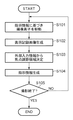
まず、S101において、指示情報生成部106から出力される指示情報に従って、撮像素子103から画像信号を読み出す。撮像素子103は指示情報に従って、前述したようにラインメモリ306に記憶された各画素を構成する2つの光電変換部PD1、PD2からのデジタル信号の読み出し方法を変える。焦点調節領域内の画素では、位相差方式の焦点調節処理を行うために光電変換部PD1、PD2のデジタル信号をそれぞれ読み出す必要があるため、タイミング制御回路307は指示情報に従ってラインメモリ306からそれぞれを独立に出力する。これに対し、焦点調節領域外の画素では、画素毎の信号が得られれば良く、光電変換部PD1、PD2毎のデジタル信号を独立に読み出す必要がない。そのため、タイミング制御回路307は指示情報に従って、ラインメモリ306から光電変換部PD1、PD2のデジタル信号を画素毎に同時に読み出し、加算処理して出力する。このように、タイミング制御回路307に出力される指示情報は、1つの画素に対して加算するしないの2値で表すことが可能である。そのため、画素1つにつき1bitのデジタルコードで生成し、それら複数のコードを多重化して撮像素子103へまとめて送ることも可能である。
First, in step S <b> 101, an image signal is read from the
次にS102において、S101において指示情報に従って撮像素子103から読み出だされた画像信号から、信号演算部104にて表示記録画像を生成する。表示記録画像とは、予め決められた画素数で構成される画像信号のことであり、信号演算部104は指示情報に従って撮像素子103から出力される任意のデータ数の画像信号を表示記録画像の画素数にする処理を行う。
In step S102, a display recording image is generated by the
ここで、信号演算部104において行われる、撮像素子103から読み出だされた画像信号を表示記録画像の画素数にする処理について説明する。図5は、信号演算部104の内部構成を示すブロック図である。図5において、501は遅延回路、502は加算回路である。選択回路503は、演算制御部505からの制御により、指示情報生成部106で生成された指示情報に従って、入力した画像信号と、加算回路502の出力とのうちいずれかを選択する。504は記憶部であり、選択回路503で選択された信号が記憶される。また、演算制御部505は記憶部504に対しても、指示情報に応じた制御信号を出力する。
Here, a process performed by the
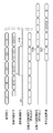
図6は、信号演算部104における信号処理を説明するためのタイミングチャートである。なお、ここでは説明の都合上、焦点調節領域を1画素として説明する。図6に示すように、撮像素子103から出力された画像信号は、時系列で順に出力される。ここでは画像信号が、A、B、C1、C2、Dと順に出力されているものとする。このうち、A、B、Dは、撮像素子103のタイミング制御回路307において画素毎に加算処理されたデジタル信号を示し、C1、C2は光電変換部PD1、PD2のデジタル信号が加算処理されずに別々に出力されたデジタル信号を示している。また、加算回路502からは、遅延回路501でデータ1つ分遅延された1画素前の信号と加算された信号が順次出力される。
FIG. 6 is a timing chart for explaining signal processing in the
選択制御信号は、演算制御部505が指示情報に従って生成した信号である。撮像素子103にも送られる指示情報は、画素203の2つの光電変換部PD1、PD2の信号をタイミング制御回路307で加算するか否かを表す情報である。そのため、信号演算部104は、この指示情報から、信号演算部104に入力される画像信号がタイミング制御回路307で加算された信号であるか否かを判別することが可能となる。この指示情報は1画素に対して加算するか否かが表現されている情報であればよく、デジタルコードで1bitで構成してもよい。また、そのようにして構成された指示情報は、演算制御部505において選択回路503を制御可能なように、図示したようなHi、Lowで表された信号に変換することで、選択回路503の制御を実現している。ここでは、選択回路503は、Lowの時に撮像素子103から入力した画像信号を選択し、Hiの時に加算回路502の出力を選択する。
The selection control signal is a signal generated by the
記憶部制御信号(書き込み)は、記憶部504に対して選択回路503の出力を書き出す際の記憶部504のアドレスを簡易的に示したものであり、選択制御信号と同様に指示情報生成部106から出力される指示情報を基に演算制御部505で生成されている。このような構成により、選択制御信号がLowの時、画像信号Aが記憶部504のアドレス0へ、画像信号Bが記憶部504のアドレス1へ、それぞれ記憶される。また、画素203の2つの光電変換部PD1、PD2から出力された画像信号C1とC2については、選択制御信号がHiの間、まず、加算回路502の出力である信号B+C1がアドレス2へ記憶される。そして、次のタイミングで、画像信号C1とC2が加算された信号C1+C2が記憶部504のアドレス2へ記憶される。これにより、アドレス2には最終的に信号C1+C2が記憶されることになる。なお、アドレスは、指示情報が焦点調節領域を示している間、同じアドレスが2回ずつ出力される。
The storage unit control signal (write) simply indicates the address of the
記憶部制御信号(読み出し)は、上述したようにして記憶部504に書き込まれた信号を読み出す際の記憶部504のアドレスを簡易的に示したものであり、演算制御部505から出力される。このアドレスに従って、表示記録画像信号として、記憶部504から画素203単位の信号が読み出される。以下同様の処理を行うことで、撮像素子103から出力された画像信号から表示記録画像を生成することが可能となる。なお、図6に示す例では、全てのアドレスから画像信号を出力する場合について示しているが、表示装置に出力する場合など、解像度を落とす必要がある場合には、記憶部504から間引き読み出しをしたり、加算読み出しなどを行う。
The storage unit control signal (reading) simply indicates the address of the
上記のように、撮像素子103の1ラインあたりにラインメモリ306に読み出される信号数は、光電変換部の数、すなわち、画素の数の2倍となる。しかしながら、そのうち、焦点調節領域以外の画素に関しては、タイミング制御回路307で信号を2つずつ加算してから出力されるため、加算せずにそれぞれ読み出す場合と比べて、読み出す時間を半分にすることができる。
As described above, the number of signals read out to the
図4に戻り、S102において、表示記録画像が生成されて、たとえばタッチパネルなどに代表される表示装置を兼ねた不図示の入力デバイスに表示されると、図3を参照して説明したようにして、焦点調節領域の指定を受け付ける。そして、S103において、焦点調節領域決定部107は、外部入力部110から送られてくる外部入力情報に応じて焦点調節領域を決定する。そして、S104において、指示情報生成部106は、焦点調節領域情報を基に、撮像素子103及び信号演算部104に対する指示情報を生成する。
Returning to FIG. 4, when a display record image is generated and displayed on an input device (not shown) that also serves as a display device represented by a touch panel or the like in S102, as described with reference to FIG. The designation of the focus adjustment area is accepted. In step S <b> 103, the focus adjustment
そしてS105において、撮影が終了したかどうかを判定する。終了した場合は本フローから抜け、終了でない場合は、S101へ戻り、S104で生成した指示情報に基づき、上述した処理を繰り返す。以下、撮影終了まで(S105でYESとなるまで)この一連の流れが繰り返される。 In step S105, it is determined whether or not shooting has been completed. If finished, exit from this flow. If not finished, return to S101 and repeat the above-described process based on the instruction information generated in S104. Thereafter, this series of steps is repeated until the end of shooting (YES in S105).
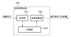
撮像素子103から出力された画像信号は、位相差算出部105にも入力され、入力された画像信号を基に、位相差方式の焦点調節AFで用いる位相差が算出される。図7は、位相差算出部105の内部構成を示すブロック図である。図7において、701は、撮像素子103から読みだされた画像信号から、焦点調節領域内の画素の光電変換部PD1、PD2の画像信号を判別する判別部である。判別部701は、指示情報生成部106で生成された、焦点調節領域を示す指示情報に基づいて選択するように構成することも可能であるが、指示情報を用いずに、次のようにして判別するように構成することもできる。即ち、撮像素子103から出力されるデジタル化された画像信号に対して、タイミング制御回路307において隣り合う2つの光電変換部PD1、PD2の出力信号を加算したか否かを判別できるような1bitの情報を付加しておく。この1bitの情報を解析することで判別するように構成することも可能である。
The image signal output from the
704は判別された画素信号を記憶する記憶部、702は相関演算部であり、記憶部704に記憶された画素信号のうち、光電変換部PD1の画像信号に基づく画像と、光電変換部PD2の画像信号に基づく画像間の相関演算を行い、位相差評価値を算出する。そして、求めた位相差評価値を、被写体までの距離情報として、AF制御部109に出力する。
位相差算出部105からの位相差評価値に基づいて、AF制御部109は目標フォーカス位置を決定し、現在のフォーカス位置からの移動方向及び移動量をフォーカス情報として、光学系駆動部102に渡す。
Based on the phase difference evaluation value from the phase
なお、焦点調節領域内の光電変換部PD1の画像信号に基づく画像と、光電変換部PD2の画像信号に基づく画像との位相差評価値に基づくAF制御は、公知の位相差方式のAF制御と同様であるので、ここでは詳細説明は省略する。 The AF control based on the phase difference evaluation value between the image based on the image signal of the photoelectric conversion unit PD1 in the focus adjustment region and the image based on the image signal of the photoelectric conversion unit PD2 is a well-known phase difference type AF control. Since it is the same, detailed description is abbreviate | omitted here.
上記の通り本第1の実施形態によれば、焦点調節領域内の画素については、光電変換部PD1、PD2の画像信号をそれぞれ読み出し、焦点調節領域外の画素については、光電変換部PD1、PD2の画像信号を画素毎に加算して読み出す。これにより、撮像素子内の任意の領域に焦点調節領域を設定できると共に、焦点調節のための位相差の算出に必要な信号を取得しながら、光電変換部PD1、PD2の画像信号を常にそれぞれ読み出す場合と比較して、読み出し時間を短縮することができる。そして、撮像素子から出力される画像信号の出力レートを上げることができる。 As described above, according to the first embodiment, the image signals of the photoelectric conversion units PD1 and PD2 are read for the pixels in the focus adjustment region, and the photoelectric conversion units PD1 and PD2 are read for the pixels outside the focus adjustment region. These image signals are added and read out for each pixel. Accordingly, the focus adjustment region can be set in an arbitrary region in the image sensor, and the image signals of the photoelectric conversion units PD1 and PD2 are always read out while acquiring signals necessary for calculating the phase difference for focus adjustment. Compared with the case, the reading time can be shortened. And the output rate of the image signal output from an image sensor can be raised.
<第2の実施形態>
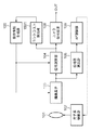
次に、本発明の第2の実施形態について説明する。図8は、第2の実施形態における撮像装置の概略構成を示すブロック図である。上述した第1の実施形態では、外部入力部110を介してユーザが指定した焦点調節領域を入力していたのに対し、本第2の実施形態では、撮像装置が自動的に焦点調節領域を決定するところが異なる。これに伴い、図1に示す外部入力部110及び焦点調節領域決定部107の代わりに、図8ではエッジ成分検出部801が追加されたところが異なる。それ以外の構成は、図1と同様であるので、同じ参照番号を付して説明を省略する。
<Second Embodiment>
Next, a second embodiment of the present invention will be described. FIG. 8 is a block diagram illustrating a schematic configuration of the imaging apparatus according to the second embodiment. In the first embodiment described above, the focus adjustment area designated by the user is input via the
本第2の実施形態においては、信号演算部104から出力される表示記録画像を基に、エッジ成分検出部801は画像信号に含まれるエッジ成分を検出し、検出したエッジ成分から焦点調節領域を決定し、焦点調節領域情報を出力する。
In the second embodiment, based on table 示記 record images outputted from the
図9は、エッジ成分検出部801の構成を示すブロック図であり、エッジ検出及びそれに基づいた焦点調節領域を決定するブロックから構成される。901は表示記録画像から、信号レベルの勾配値を算出する微分フィルタであり、例えば、既知のSobelフィルタで構成することができる。902は、算出された勾配値を絶対値化する絶対値算出部である。903は、分割領域毎に各画素の勾配値の絶対値を積算し、分割領域勾配値を求める分割領域絶対値算出部である。なお、ここでいう分割領域とは、例えば表示記録画像を縦横にNxMに均等分割することで決定される区画を示している。905は、各分割領域の勾配値の絶対値を記憶する記憶部、904は、分割領域勾配値と予め定められた指標とに基づいて焦点調節領域を決定し、焦点調節領域情報として指示情報生成部106へ送る焦点調節領域判定部である。
FIG. 9 is a block diagram showing the configuration of the edge
上述した構成を有するエッジ成分検出部801を用いる本第2の実施形態においては、第1の実施形態において図4のS103において行われた焦点調節領域の決定処理の代わりに、図10に示す、エッジ検出結果に基づく焦点調節領域決定処理が行われる。それ以外の処理は、図4を参照して説明した処理と同様であるため、ここでは説明を省略する。
In the second embodiment using the edge
図10は、エッジ成分の検出及び焦点調節領域の決定処理のフローチャートである。エッジ成分の検出処理が開始されると、S201において、微分フィルタ901で画素毎に勾配値を算出し、絶対値算出部902において、算出された勾配値の絶対値を画素毎に算出する。S202では、分割領域絶対値算出部903において、絶対値化された画素毎の勾配値を分割領域毎に積算し、分割領域勾配値を算出する。S203で、記憶部905に分割領域勾配値を記憶し、S204で記憶部905に記憶された分割領域勾配値を基に、焦点調節領域を判定する。ここでは、算出された分割領域勾配値の平均値を閾値とし、該閾値と各分割領域勾配値とを比較して、閾値より大きい分割領域を焦点調節領域候補とする。あるいは、分割領域勾配値の平均値ではなく、予め定められた閾値を用いて焦点調節領域候補を決定してもよい。
FIG. 10 is a flowchart of edge component detection and focus adjustment region determination processing. When the edge component detection process is started, the gradient value is calculated for each pixel by the
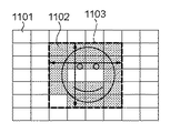
図11は、焦点調節領域判定後の表示記録画像を示している。1101は前述した分割領域を示しており、水平8x垂直7の計56の分割領域に分割され、表示記録画像は図のようなおおまかな区分けが成されている。1102は、分割領域勾配値が閾値より大きい分割領域、すなわち、焦点調節領域候補を灰色で示している。このように決定された焦点調節領域候補を含む矩形1103の領域が焦点調節領域として決定され、焦点調節領域情報として指示情報生成部106へ送られる。
FIG. 11 shows the display recording image after the focus adjustment area determination.
上記の通り本第2の実施形態によれば、撮像して得られた画像からエッジ成分の検出を行って自動的に焦点調節領域を決定するので、ユーザの手を煩わすことなく、第1の実施形態と同様の効果を得ることができる。 As described above, according to the second embodiment, the edge component is detected from the image obtained by imaging, and the focus adjustment area is automatically determined. Therefore, the first operation is performed without bothering the user. The same effect as the embodiment can be obtained.
<第3の実施形態>
次に、本発明の第3の実施形態について説明する。図12は、第3の実施形態における撮像装置の概略構成を示すブロック図である。上述した第2の実施形態では、表示記録画像から検出されたエッジ成分に基づいて焦点調節領域を決定していたのに対し、本第3の実施形態では、表示記録画像に含まれる主被写体の顔を検出し、検出した顔に基づいて焦点調節領域を決定するところが異なる。これに伴い、図8に示すエッジ成分検出部801の代わりに、図12では被写体顔検出部1201が追加されたところが異なる。それ以外の構成は、図8と同様であるので、同じ参照番号を付して説明を省略する。
<Third Embodiment>
Next, a third embodiment of the present invention will be described. FIG. 12 is a block diagram illustrating a schematic configuration of an imaging apparatus according to the third embodiment. In the second embodiment described above, the focus adjustment area is determined based on the edge component detected from the display recording image. In the third embodiment, the main subject included in the display recording image is determined. The difference is that a face is detected and a focus adjustment region is determined based on the detected face. Accordingly, the subject
本第3の実施形態においては、被写体顔検出部1201は、表示記録画像から被写体の顔を検出し、その顔が含まれる領域を焦点調節領域として決定し、焦点調節領域情報を出力する。
In the third embodiment, the subject
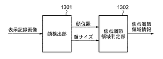
図13は、被写体顔検出部1201の構成を示すブロック図である。1301は被写体の顔を検出する顔検出部であり、少なくとも検出した被写体の顔の大きさおよび顔の位置情報を出力する。なお、顔検出方法としては様々な方法が知られており、どのような方法を用いても構わない。1302は、顔検出部1301から出力された顔の大きさおよび顔の位置情報を基に、焦点調節領域を決定する焦点調節領域判定部である。
FIG. 13 is a block diagram illustrating a configuration of the subject
図14は、被写体顔検出部1201により検出された顔と、決定された焦点調節領域を示している。1401は、顔検出部1301によって検出された顔の位置と顔のサイズを示し、1402は、顔の位置と顔のサイズに基づいて決定された焦点調節領域を示している。焦点調節領域の決定の仕方としては、例えば、検出された顔を含む、表示記録画像を縦横にNxMに均等分割することで決定される分割領域を焦点調節領域として決定しても良い。また、顔の領域そのものを焦点調節領域としたり、中央部分が検出された顔の領域の中心と重なるような、予め決められた大きさの焦点調節領域を決定するなど、別の方法により決定しても良い。被写体顔検出部1201は、このようにして決定された焦点調節領域の焦点調節領域情報を指示情報生成部106へ渡す。
FIG. 14 shows the face detected by the subject
上述した検出した顔に基づく焦点調節領域の決定処理は、第1の実施形態において図4のS103において行われた焦点調節領域の決定処理の代わりに行われる。それ以外の処理は、図4を参照して説明した処理と同様であるため、ここでは説明を省略する。 The focus adjustment area determination process based on the detected face described above is performed instead of the focus adjustment area determination process performed in S103 of FIG. 4 in the first embodiment. The other processes are the same as those described with reference to FIG.
上記の通り第3の実施形態によれば、第1の実施形態と同様の効果に加えて、自動的に主被写体の顔に対して精度よく焦点調節を行うことができる。 As described above, according to the third embodiment, in addition to the same effects as those of the first embodiment, it is possible to automatically perform focus adjustment on the face of the main subject with high accuracy.
なお、上記第3の実施形態では、主被写体の顔(人物の顔)を検出する場合について説明したが、本第3の実施形態はこれに限るものではなく、ペットや車など、予め決められた被写体を検出するようにしてもよい。 In the third embodiment, the case where the face of the main subject (person's face) is detected has been described. However, the third embodiment is not limited to this, and a pet, a car, or the like can be determined in advance. The subject may be detected.
<第4の実施形態>
次に、本発明の第4の実施形態について説明する。図15は、第4の実施形態における撮像装置の概略構成を示すブロック図である。上述した第2の実施形態では、表示記録画像から検出されたエッジ成分に基づいて、また、上述した第3の実施形態では、表示記録画像から検出された主被写体の顔に基づいて焦点調節領域を決定した。これに対し、本第4の実施形態では、表示記録画像からコントラスト値の大きい領域を検出し、検出した領域を焦点調節領域とするところが異なる。これに伴い、図15ではコントラスト検出部1501を有するところが、図1、図8及び図12と異なるが、それ以外の構成は同様であるので、同じ参照番号を付して説明を省略する。
<Fourth Embodiment>
Next, a fourth embodiment of the present invention will be described. FIG. 15 is a block diagram illustrating a schematic configuration of an imaging apparatus according to the fourth embodiment. In the second embodiment described above, the focus adjustment area is based on the edge component detected from the display recording image, and in the third embodiment, based on the face of the main subject detected from the display recording image. It was determined. On the other hand, the fourth embodiment is different in that a region having a large contrast value is detected from the display recording image, and the detected region is set as a focus adjustment region. Accordingly, FIG. 15 has a
図16は、コントラスト検出部1501の構成を示すブロック図である。1601は、分割領域毎に標準偏差を算出する標準偏差算出部である。なお、ここでいう分割領域とは、例えば表示記録画像を縦横にNxMに均等分割することで決定される区画を示している。標準偏差算出部1601は、各区画内の画素レベルの標準偏差、すなわち画素レベルの明暗の差を算出する。1603は、算出された各分割領域における標準偏差を記憶する記憶部、1602は、各分割領域の標準偏差と予め定められた指標値に基づいて、焦点調節領域を決定し、焦点調節領域情報を指示情報生成部106へ送る焦点調節領域判定部である。
FIG. 16 is a block diagram illustrating a configuration of the
上述した構成を有するコントラスト検出部1501を用いる本第4の実施形態においては、第1の実施形態において図4のS103において行われた焦点調節領域の決定処理の代わりに、図17に示す、コントラスト値に基づく焦点調節領域決定処理が行われる。それ以外の処理は、図4を参照して説明した処理と同様であるため、ここでは説明を省略する。
In the fourth embodiment using the
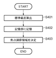
コントラスト検出が開始されると、S401において、標準偏差算出部1601において、分割領域毎に標準偏差が算出される。そして、S402で、記憶部1603に算出した各分割領域の標準偏差を記憶し、S403で、記憶部1603に記憶された各分割領域の標準偏差を基に、焦点調節領域を判定する。ここでは、算出された分割領域の標準偏差の平均値を閾値とし、該閾値と各分割領域の標準偏差を比較して、閾値より大きい分割領域を焦点調節領域候補とする。あるいは、各分割領域の標準偏差の平均値ではなく予め定められた閾値を用いて焦点調節領域候補を決定してもよい。
When contrast detection is started, in S401, the standard deviation is calculated for each divided region in the standard
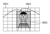
図18は、焦点調節領域判定後の表示記録画像を示している。1801は前述した分割領域を示しており、水平8x垂直7の計56の分割領域に分割され、表示記録画像は図のようなおおまかな区分けが成されている。1802は、標準偏差が該閾値より大きい分割領域、すなわち、焦点調節領域候補を灰色で示している。このように決定された焦点調節領域候補を含む矩形1803の領域が焦点調節領域として決定され、焦点調節領域情報として指示情報生成部106へ送られる。
FIG. 18 shows a display recording image after the focus adjustment area determination.
上記の通り、本第4の実施形態によれば、撮影して得られた画像から、焦点調節に適したコントラストの高い部分を含む領域を自動的に焦点調節領域として決定するので、第1の実施形態と同様の効果に加えて、精度の高い焦点調節を行うことができる。 As described above, according to the fourth embodiment, an area including a high-contrast portion suitable for focus adjustment is automatically determined as a focus adjustment area from an image obtained by photographing. In addition to the same effects as those of the embodiment, highly accurate focus adjustment can be performed.
Claims (7)
前記撮像素子における焦点調節を行う対象領域である焦点調節領域を決定する決定手段とを有し、
前記制御手段は、各行の読み出し中に、前記焦点調節領域内の前記光電変換部から出力された前記画像信号を非加算でそれぞれ出力し、前記焦点調節領域外の前記光電変換部から出力された前記画像信号を加算して出力するように切り替え、更に、
前記焦点調節領域内の前記光電変換部から出力された前記非加算の画像信号に基づいて、位相差方式の焦点調節制御を行う焦点調節手段と、
前記撮像素子から出力された画像信号のうち、前記焦点調節領域内の前記非加算の画像信号を前記各マイクロレンズに対応する複数の光電変換部毎に加算すると共に、前記焦点調節領域外の前記加算した画像信号をそのまま出力する信号演算手段とを有し、
前記決定手段は、前記信号演算手段から出力された画像信号の画像を用いて前記焦点調節領域を決定することを特徴とする撮像装置。 A plurality of microlenses, and a plurality of photoelectric conversion units configured for each microlens, a storage means for storing the images signals output from the respective photoelectric conversion portions, respectively, before SL stored in the storage means an image pickup device and a control means for the images signals in the non-addition or outputs, or the image signal adding to said each plurality of photoelectric conversion units corresponding to each microlens switching between the outputs,
And a determination means for determining a focus control area is a target area for focusing in the previous SL imaging device,
Wherein, in each row of the read, the outputs respectively Kiga image signals before outputted from the photoelectric conversion unit of the focus adjustment area in the non-addition, the output from the photoelectric conversion portion outside the focusing area the Kiga image signal before being switched to the summing and output, further,
Focus adjustment means for performing phase difference type focus adjustment control based on the non-addition image signal output from the photoelectric conversion unit in the focus adjustment region;
Among the image signals output from the image sensor, the non-added image signal in the focus adjustment area is added for each of a plurality of photoelectric conversion units corresponding to the micro lenses, and the outside of the focus adjustment area Signal calculating means for outputting the added image signal as it is,
It said determination means, the image pickup apparatus characterized that you determine the focus control area using the image of the image signal output from the signal operation unit.
前記決定手段は、前記入力手段からの入力に基づいて、前記焦点調節領域を決定することを特徴とする請求項1に記載の撮像装置。 An input means for the user to specify the focus adjustment area;
The imaging apparatus according to claim 1, wherein the determination unit determines the focus adjustment region based on an input from the input unit.
前記決定手段は、前記エッジ成分が検出された領域を含む領域を、前記焦点調節領域として決定することを特徴とする請求項1に記載の撮像装置。 Further comprising edge detection means for detecting an edge component of the image based on the image signal output from the signal calculation means,
The imaging apparatus according to claim 1 , wherein the determination unit determines a region including a region where the edge component is detected as the focus adjustment region.
前記決定手段は、前記被写体が検出された領域を含む領域を、前記焦点調節領域として決定することを特徴とする請求項1に記載の撮像装置。 Further comprising detection means for detecting a predetermined subject based on the image signal output from the signal calculation means;
The imaging apparatus according to claim 1 , wherein the determination unit determines an area including an area where the subject is detected as the focus adjustment area.
前記決定手段は、前記コントラスト検出手段が検出した領域を含む領域を、前記焦点調節領域として決定することを特徴とする請求項1に記載の撮像装置。 Contrast detection means for detecting a region where the contrast is higher than a preset threshold based on the image signal output from the signal calculation means;
The imaging apparatus according to claim 1 , wherein the determination unit determines a region including a region detected by the contrast detection unit as the focus adjustment region.
決定手段が、前記撮像素子における焦点調節を行う対象領域である焦点調節領域を決定する決定工程と、
前記制御手段が、各行の読み出し中に、前記焦点調節領域内の前記光電変換部から出力された前記画像信号を非加算でそれぞれ出力し、前記焦点調節領域外の前記光電変換部から出力された前記画像信号を加算して出力するように切り替える制御工程と、
焦点調節手段が、前記焦点調節領域内の前記光電変換部から出力された前記非加算の画像信号に基づいて、位相差方式の焦点調節制御を行う焦点調節工程と、
信号演算手段が、前記撮像素子から出力された画像信号のうち、前記焦点調節領域内の前記非加算の画像信号を前記各マイクロレンズに対応する複数の光電変換部毎に加算すると共に、前記焦点調節領域外の前記加算した画像信号をそのまま出力する信号演算工程とを有し、
前記決定工程では、前記信号演算工程で出力された画像信号の画像を用いて前記焦点調節領域を決定することを特徴とする撮像装置の制御方法。 A plurality of microlenses, and a plurality of photoelectric conversion units configured for each microlens, a storage means for storing the images signals output from the respective photoelectric conversion portions, respectively, before SL stored in the storage means an image pickup apparatus having an image pickup device and a control unit that switches whether to output the images signals in the non-addition, or whether the adding and outputting the image signal for each of a plurality of photoelectric conversion units corresponding to each microlens Control method,
Determining means, a determination step of determining a focus control area is a target area for focusing in the previous SL imaging device,
Said control means, in each row of the read, the outputs respectively Kiga image signals before outputted from the photoelectric conversion unit of the focus adjustment area in the non-addition, the output from the photoelectric conversion portion outside the focusing area switching control step as the Kiga image signal to the summing and output before are,
A focus adjustment step for performing focus adjustment control of a phase difference method based on the non-addition image signal output from the photoelectric conversion unit in the focus adjustment region ;
The signal calculation means adds the non-addition image signal in the focus adjustment area among the image signals output from the image sensor for each of the plurality of photoelectric conversion units corresponding to the microlenses, and the focus. A signal calculation step of outputting the added image signal outside the adjustment region as it is,
In the determination step, the focus adjustment region is determined using an image of the image signal output in the signal calculation step .
Priority Applications (2)
| Application Number | Priority Date | Filing Date | Title |
|---|---|---|---|
| JP2011013370A JP5778931B2 (en) | 2011-01-25 | 2011-01-25 | Imaging apparatus and control method thereof |
| US13/352,789 US8830354B2 (en) | 2011-01-25 | 2012-01-18 | Image capturing apparatus and control method thereof |
Applications Claiming Priority (1)
| Application Number | Priority Date | Filing Date | Title |
|---|---|---|---|
| JP2011013370A JP5778931B2 (en) | 2011-01-25 | 2011-01-25 | Imaging apparatus and control method thereof |
Publications (3)
| Publication Number | Publication Date |
|---|---|
| JP2012155095A JP2012155095A (en) | 2012-08-16 |
| JP2012155095A5 JP2012155095A5 (en) | 2014-03-06 |
| JP5778931B2 true JP5778931B2 (en) | 2015-09-16 |
Family
ID=46543918
Family Applications (1)
| Application Number | Title | Priority Date | Filing Date |
|---|---|---|---|
| JP2011013370A Expired - Fee Related JP5778931B2 (en) | 2011-01-25 | 2011-01-25 | Imaging apparatus and control method thereof |
Country Status (2)
| Country | Link |
|---|---|
| US (1) | US8830354B2 (en) |
| JP (1) | JP5778931B2 (en) |
Families Citing this family (25)
| Publication number | Priority date | Publication date | Assignee | Title |
|---|---|---|---|---|
| CN107509029A (en) * | 2013-01-07 | 2017-12-22 | 华为技术有限公司 | An image processing method and device |
| JP6335482B2 (en) * | 2013-11-13 | 2018-05-30 | キヤノン株式会社 | Imaging apparatus, control method therefor, and program |
| JP6189191B2 (en) * | 2013-11-21 | 2017-08-30 | Dmg森精機株式会社 | Surface shape measuring device and machine tool |
| US9354489B2 (en) * | 2014-02-10 | 2016-05-31 | Raytheon Company | Robust autofocus algorithm for multi-spectral imaging systems |
| JP6212717B2 (en) | 2014-03-26 | 2017-10-18 | パナソニックIpマネジメント株式会社 | Imaging device |
| JP6296887B2 (en) * | 2014-05-07 | 2018-03-20 | キヤノン株式会社 | Focus adjustment apparatus and control method thereof |
| JP6501536B2 (en) * | 2015-02-02 | 2019-04-17 | キヤノン株式会社 | Imaging device, control method therefor, program, storage medium |
| KR102328098B1 (en) * | 2015-02-13 | 2021-11-17 | 삼성전자주식회사 | Apparatus and method for focusing of carmea device or an electronic device having a camera module |
| JP6594048B2 (en) * | 2015-05-29 | 2019-10-23 | キヤノン株式会社 | Imaging apparatus and control method thereof |
| JP6442362B2 (en) | 2015-05-29 | 2018-12-19 | キヤノン株式会社 | Image pickup apparatus and image pickup element control method |
| JP2017108281A (en) * | 2015-12-09 | 2017-06-15 | 株式会社ニコン | Imaging device and imaging apparatus |
| JP6702777B2 (en) | 2016-04-12 | 2020-06-03 | キヤノン株式会社 | Imaging device, imaging method, and program |
| JP6678505B2 (en) | 2016-04-22 | 2020-04-08 | キヤノン株式会社 | Imaging device, control method therefor, program, and storage medium |
| JP6678504B2 (en) | 2016-04-22 | 2020-04-08 | キヤノン株式会社 | Imaging device, control method therefor, program, and storage medium |
| JP6748477B2 (en) | 2016-04-22 | 2020-09-02 | キヤノン株式会社 | Imaging device, control method thereof, program, and storage medium |
| JP6765859B2 (en) | 2016-05-31 | 2020-10-07 | キヤノン株式会社 | Imaging device and its control method |
| JP2018026768A (en) * | 2016-08-12 | 2018-02-15 | キヤノン株式会社 | Imaging apparatus, control method of the same, and program |
| JP6741549B2 (en) | 2016-10-14 | 2020-08-19 | キヤノン株式会社 | Imaging device and control method thereof |
| JP6793053B2 (en) * | 2017-02-09 | 2020-12-02 | リコーエレメックス株式会社 | Inspection device and focus adjustment support method |
| JP7136080B2 (en) * | 2017-03-08 | 2022-09-13 | ソニーグループ株式会社 | Imaging device, imaging method, image processing device, and image processing method |
| JP6953163B2 (en) | 2017-04-04 | 2021-10-27 | キヤノン株式会社 | Imaging device and control method |
| JP6944846B2 (en) | 2017-10-04 | 2021-10-06 | オリンパス株式会社 | Imaging device, control method of imaging device |
| WO2020150223A1 (en) * | 2019-01-15 | 2020-07-23 | Schlumberger Technology Corporation | Residual signal detection for noise attenuation |
| JP6849107B2 (en) * | 2020-01-06 | 2021-03-24 | 株式会社ニコン | Image sensor and image sensor |
| JP2021061618A (en) * | 2020-12-15 | 2021-04-15 | 株式会社ニコン | Imaging device and imaging apparatus |
Family Cites Families (13)
| Publication number | Priority date | Publication date | Assignee | Title |
|---|---|---|---|---|
| US6819360B1 (en) * | 1999-04-01 | 2004-11-16 | Olympus Corporation | Image pickup element and apparatus for focusing |
| JP3774597B2 (en) * | 1999-09-13 | 2006-05-17 | キヤノン株式会社 | Imaging device |
| JP5002086B2 (en) * | 1999-10-28 | 2012-08-15 | キヤノン株式会社 | Focus detection device and imaging device |
| JP2001304855A (en) * | 2000-04-18 | 2001-10-31 | Olympus Optical Co Ltd | Range finder |
| JP4708595B2 (en) * | 2001-05-09 | 2011-06-22 | キヤノン株式会社 | Imaging apparatus and camera |
| WO2007011026A1 (en) * | 2005-07-22 | 2007-01-25 | Nikon Corporation | Imaging element, focal point detecting device, and imaging system |
| JP4835270B2 (en) | 2006-06-03 | 2011-12-14 | 株式会社ニコン | Solid-state imaging device and imaging apparatus using the same |
| JP4979482B2 (en) * | 2007-06-28 | 2012-07-18 | オリンパス株式会社 | Imaging apparatus and image signal processing program |
| US8319870B2 (en) * | 2008-02-22 | 2012-11-27 | Panasonic Corporation | Imaging apparatus |
| JP5247279B2 (en) * | 2008-07-17 | 2013-07-24 | キヤノン株式会社 | Imaging apparatus, control method thereof, and program |
| JP5617157B2 (en) * | 2008-08-20 | 2014-11-05 | 株式会社ニコン | Focus detection apparatus and imaging apparatus |
| JP5489641B2 (en) * | 2008-11-11 | 2014-05-14 | キヤノン株式会社 | Focus detection apparatus and control method thereof |
| JP5446311B2 (en) * | 2009-02-20 | 2014-03-19 | 株式会社ニコン | Imaging device |
-
2011
- 2011-01-25 JP JP2011013370A patent/JP5778931B2/en not_active Expired - Fee Related
-
2012
- 2012-01-18 US US13/352,789 patent/US8830354B2/en not_active Expired - Fee Related
Also Published As
| Publication number | Publication date |
|---|---|
| US8830354B2 (en) | 2014-09-09 |
| US20120188408A1 (en) | 2012-07-26 |
| JP2012155095A (en) | 2012-08-16 |
Similar Documents
| Publication | Publication Date | Title |
|---|---|---|
| JP5778931B2 (en) | Imaging apparatus and control method thereof | |
| RU2679011C1 (en) | Image sensor and image capture device | |
| JP6039165B2 (en) | Imaging device and imaging apparatus | |
| US9204030B2 (en) | Image pickup apparatus and control method thereof | |
| US9025074B2 (en) | Image capturing apparatus and method for controlling the same | |
| US9071781B2 (en) | Image capturing apparatus and defective pixel detection method | |
| CN110225242B (en) | Imaging element, control method of imaging element, and imaging device | |
| JP6748454B2 (en) | Imaging device, control method thereof, program, and storage medium | |
| JP6099904B2 (en) | Imaging device | |
| KR20190029615A (en) | Image pickup apparatus and control method of image pickup apparatus | |
| JP6381274B2 (en) | Imaging device, control method thereof, and control program | |
| JP2007150643A (en) | Solid-state imaging device, solid-state imaging device driving method, and imaging apparatus | |
| CN103891267A (en) | Image sensing device and imaging device | |
| JP2013057915A (en) | Imaging device and control method of the same | |
| US20170019583A1 (en) | Image sensor and driving method thereof, and image capturing apparatus | |
| US20160353043A1 (en) | Image sensor and image apparatus | |
| CN105407299A (en) | Image Capturing Apparatus And Method Of Controlling Image Capturing Apparatus | |
| JP6759088B2 (en) | Imaging device and its control method and program | |
| JP2015148676A (en) | Imaging apparatus and method of controlling imaging apparatus | |
| JP6594048B2 (en) | Imaging apparatus and control method thereof | |
| JP6127368B2 (en) | Imaging device | |
| US10855887B2 (en) | Image capturing apparatus, image processing apparatus, and control method therefor | |
| JP2015049283A (en) | IMAGING DEVICE, IMAGING SYSTEM, IMAGING DEVICE CONTROL METHOD, PROGRAM, AND STORAGE MEDIUM | |
| JP2015166799A (en) | Imaging apparatus, imaging method, and program thereof | |
| JP2018182549A (en) | Imaging device |
Legal Events
| Date | Code | Title | Description |
|---|---|---|---|
| A521 | Request for written amendment filed |
Free format text: JAPANESE INTERMEDIATE CODE: A523 Effective date: 20140120 |
|
| A621 | Written request for application examination |
Free format text: JAPANESE INTERMEDIATE CODE: A621 Effective date: 20140120 |
|
| A977 | Report on retrieval |
Free format text: JAPANESE INTERMEDIATE CODE: A971007 Effective date: 20141107 |
|
| A131 | Notification of reasons for refusal |
Free format text: JAPANESE INTERMEDIATE CODE: A131 Effective date: 20141114 |
|
| A521 | Request for written amendment filed |
Free format text: JAPANESE INTERMEDIATE CODE: A523 Effective date: 20150113 |
|
| TRDD | Decision of grant or rejection written | ||
| A01 | Written decision to grant a patent or to grant a registration (utility model) |
Free format text: JAPANESE INTERMEDIATE CODE: A01 Effective date: 20150612 |
|
| A61 | First payment of annual fees (during grant procedure) |
Free format text: JAPANESE INTERMEDIATE CODE: A61 Effective date: 20150710 |
|
| R151 | Written notification of patent or utility model registration |
Ref document number: 5778931 Country of ref document: JP Free format text: JAPANESE INTERMEDIATE CODE: R151 |
|
| LAPS | Cancellation because of no payment of annual fees |