JP6748477B2 - Imaging device, control method thereof, program, and storage medium - Google Patents
Imaging device, control method thereof, program, and storage medium Download PDFInfo
- Publication number
- JP6748477B2 JP6748477B2 JP2016086574A JP2016086574A JP6748477B2 JP 6748477 B2 JP6748477 B2 JP 6748477B2 JP 2016086574 A JP2016086574 A JP 2016086574A JP 2016086574 A JP2016086574 A JP 2016086574A JP 6748477 B2 JP6748477 B2 JP 6748477B2
- Authority
- JP
- Japan
- Prior art keywords
- region
- signals
- unit
- state
- image
- Prior art date
- Legal status (The legal status is an assumption and is not a legal conclusion. Google has not performed a legal analysis and makes no representation as to the accuracy of the status listed.)
- Active
Links
Images


Classifications
-
- H—ELECTRICITY
- H04—ELECTRIC COMMUNICATION TECHNIQUE
- H04N—PICTORIAL COMMUNICATION, e.g. TELEVISION
- H04N23/00—Cameras or camera modules comprising electronic image sensors; Control thereof
- H04N23/60—Control of cameras or camera modules
- H04N23/67—Focus control based on electronic image sensor signals
- H04N23/672—Focus control based on electronic image sensor signals based on the phase difference signals
-
- G—PHYSICS
- G06—COMPUTING; CALCULATING OR COUNTING
- G06T—IMAGE DATA PROCESSING OR GENERATION, IN GENERAL
- G06T7/00—Image analysis
- G06T7/70—Determining position or orientation of objects or cameras
Landscapes
- Engineering & Computer Science (AREA)
- Multimedia (AREA)
- Signal Processing (AREA)
- Computer Vision & Pattern Recognition (AREA)
- Physics & Mathematics (AREA)
- General Physics & Mathematics (AREA)
- Theoretical Computer Science (AREA)
- Focusing (AREA)
- Automatic Focus Adjustment (AREA)
- Studio Devices (AREA)
- Transforming Light Signals Into Electric Signals (AREA)
Description
本発明は、焦点調節及び被写体検出を行う撮像装置に関する。 The present invention relates to an imaging device that performs focus adjustment and subject detection.
従来より、マイクロレンズにより瞳分割された画素を有する撮像素子により得られた像信号の位相差に基づいて焦点検出を行う技術が知られている(特許文献1)。特許文献1では、瞳分割された各画素がマイクロレンズを介して結像光学系の異なる瞳領域を通過した光束を受光する。また、複数の像信号を加算することで画像信号を得ることができる。
BACKGROUND ART Conventionally, there is known a technique for performing focus detection based on the phase difference of image signals obtained by an image pickup device having pixels whose pupils are divided by a microlens (Patent Document 1). In
上記のような位相差方式の焦点検出においては、焦点調節用にどのくらいの量の像信号を読み出して演算処理を行うかを決めることは検出精度や処理速度の面で非常に重要な要素となる。また、像信号を全て取り込もうとすると、画素が2分割された撮像素子では撮像画像用の2倍のデータ量となり、後段の処理回路に多大な負荷をかけることになる。 In the phase difference type focus detection as described above, it is a very important factor in terms of detection accuracy and processing speed to decide how much image signal for focus adjustment is read and arithmetic processing is performed. .. Further, if all the image signals are to be taken in, the image pickup device in which the pixels are divided into two has a double data amount for the picked-up image, which imposes a great load on the processing circuit in the subsequent stage.
そこで、撮像素子において焦点調節用の距離情報取得領域を任意に設定可能とし、撮像素子からの画像信号の読み出し時間を短縮する撮像装置が提案されている(特許文献2)。また、焦点調節用の距離情報取得領域から得た画像信号を用いて、画像中の被写体の距離の分布(距離マップ)を生成可能な撮像装置が提案されている(特許文献3)。特許文献3の距離マップを用いることで、画像中における主被写体とそれ以外の被写体の距離情報が得られ、主被写体とそれ以外の被写体がすれ違った場合等に主被写体の検出が可能となる。
Therefore, an imaging device has been proposed in which a distance information acquisition region for focus adjustment can be arbitrarily set in the image sensor to shorten the time taken to read an image signal from the image sensor (Patent Document 2). Further, there is proposed an imaging device that can generate a distribution of distances (distance map) of a subject in an image by using an image signal obtained from a distance information acquisition area for focus adjustment (Patent Document 3). By using the distance map of
しかしながら、上記従来技術において、焦点調節用の距離情報取得領域と被写体検出用距離情報取得領域とは必ずしも一致しないため、いずれか一方に合わせると、もう一方の精度が低下する可能性がある。 However, in the above-mentioned conventional technique, the distance information acquisition area for focus adjustment and the distance information acquisition area for subject detection do not necessarily match, so if one of them is matched, the accuracy of the other may decrease.
本発明は、上記課題に鑑みてなされ、その目的は、焦点調節の精度と被写体検出の精度とを両立できるようにすることである。 The present invention has been made in view of the above problems, and an object thereof is to make the accuracy of focus adjustment and the accuracy of subject detection compatible with each other.
上記課題を解決し、目的を達成するために、本発明の撮像装置は、複数のマイクロレンズを有し、当該複数のマイクロレンズそれぞれに複数の光電変換部が割り当てられて、当該複数の光電変換部ごとに1つの画素をなす撮像素子と、前記撮像素子の光電変換部から順次信号を読み出し、前記撮像素子の各画素における複数の光電変換部からの信号に対応する複数画素からなる画像信号を複数フレーム出力させる読み出し手段と、主被写体に対応する領域を示す情報と、当該主被写体の合焦状態を示す情報とを取得する取得手段と、前記読み出し手段により前記撮像素子から視差が異なる信号を読み出す領域を設定する設定手段と、を有し、前記設定手段は、前記視差が異なる信号を読み出す領域の設定として第1の領域と、当該第1の領域よりも包含する画角が広く、かつ前記第1の領域より前記画角内で前記視差が異なる信号を読み出すラインの間隔が広い第2の領域とを設定可能であり、各フレームにおける前記視差が異なる信号を読み出す領域について、前記主被写体の合焦状態が第1の状態であるときには、当該第1の状態よりも合焦に遠い第2の状態であるときよりも前記第2の領域で前記視差が異なる信号が読み出されるフレームの頻度が高くなるように設定する。 In order to solve the above problems and achieve an object, an imaging device of the present invention has a plurality of microlenses, and a plurality of photoelectric conversion units are assigned to each of the plurality of microlenses, and the plurality of photoelectric conversion units are assigned. An image signal including a plurality of pixels corresponding to signals from a plurality of photoelectric conversion units in each pixel of the image sensor is sequentially read out from an image sensor that forms one pixel for each unit and a photoelectric conversion unit of the image sensor. reading means for multiple frame output, and information indicating a region corresponding to the main object, an acquisition unit configured to acquire information indicating a focus state of the main subject, a different signal parallax from the imaging device by said reading means a setting means for setting a region to be read, wherein the setting means comprises a first region as the setting of a region where the parallax reads different signals, widely encompasses angle than the first region, and It is possible to set a second area in which the intervals of lines for reading out the signals with different parallaxes within the angle of view are wider than the first area, and for the area for reading out signals with different parallaxes in each frame, the main subject frequency focusing state when a first state, the frame in which the in the second region than when a distant second state focusing than the first state parallax different signal is read out Is set to be high.
また、本発明の撮像装置は、複数のマイクロレンズを有し、当該複数のマイクロレンズそれぞれに複数の光電変換部が割り当てられて、当該複数の光電変換部ごとに1つの画素をなす撮像素子と、前記撮像素子の光電変換部から順次信号を読み出し、前記撮像素子の各画素における複数の光電変換部からの信号に対応する複数画素からなる画像信号を複数フレーム出力させる読み出し手段と、主被写体に対応する領域を示す情報と、当該主被写体の合焦状態を示す情報とを取得する取得手段と、前記読み出し手段により前記撮像素子から視差が異なる信号を読み出す領域を設定する設定手段と、を有し、前記設定手段は、前記視差が異なる信号を読み出す領域の設定として第1の領域と、当該第1の領域よりも包含する画角が広く、かつ前記第1の領域より前記画角内で前記視差が異なる信号を読み出すラインの間隔が広い第2の領域とを設定可能であり、各フレームの読み出しにおいて、前記主被写体の合焦状態が第1の状態であるときに前記第2の領域に設定し、前記主被写体の合焦状態が前記第1の状態よりも合焦に遠い第2の状態であるときに前記第1の領域に設定する。 In addition, the image pickup device of the present invention includes a plurality of microlenses, a plurality of photoelectric conversion units are assigned to the plurality of microlenses, and an image pickup device that forms one pixel for each of the plurality of photoelectric conversion units. Reading means for sequentially reading out signals from the photoelectric conversion unit of the image sensor and outputting a plurality of frames of image signals composed of a plurality of pixels corresponding to signals from a plurality of photoelectric conversion units in each pixel of the image sensor; Yes information indicating the corresponding region, an acquisition unit configured to acquire information indicating a focus state of the main subject, and a setting means for parallax from the imaging device to set the area for reading a different signal by said reading means and said setting means comprises a first region as the setting of a region where the parallax reads the different signals, the wide encompasses angle than the first region, and in the first of the angle of view than the region It is possible to set a second area in which the intervals of the lines for reading the signals with different parallax are wide, and in the reading of each frame, the second area when the focus state of the main subject is the first state. set is set to the first area when focus state of the main subject is a distant second state focusing than the first state.
本発明によれば、焦点調節の精度と被写体検出の精度とを両立できるようになる。 According to the present invention, it is possible to achieve both the accuracy of focus adjustment and the accuracy of subject detection.
以下に、本発明を実施するための形態について詳細に説明する。尚、以下に説明する実施の形態は、本発明を実現するための一例であり、本発明が適用される装置の構成や各種条件によって適宜修正又は変更されるべきものであり、本発明は以下の実施の形態に限定されるものではない。また、後述する各実施形態の一部を適宜組み合わせて構成してもよい。 Hereinafter, modes for carrying out the present invention will be described in detail. The embodiment described below is an example for realizing the present invention, and should be appropriately modified or changed according to the configuration of the device to which the present invention is applied and various conditions. However, the present invention is not limited to the embodiment. In addition, a part of each embodiment described below may be appropriately combined and configured.
[背景の説明]まず、図16を参照して、本実施形態の背景について具体的に説明する。 [Description of Background] First, the background of the present embodiment will be specifically described with reference to FIG. 16.
図16は、画像撮影中のAF制御時に、撮像画面に任意に設定された、焦点調節に必要となる(AF制御用)の距離情報取得領域及びその距離マップと、被写体検出に必要となる(主被写体追尾用)の距離情報取得領域及びその距離マップの関係を例示している。なお、図16の(a)、(b)、(c)において、(a−1)〜(a−4)、(b−1)〜(b−4)、(c−1)〜(c−4)、(d−1)〜(d−4)は、撮像された画像信号の各フレームを時系列的に示したものである。 FIG. 16 shows a distance information acquisition area (for AF control) necessary for focus adjustment and a distance map thereof, which is arbitrarily set on the imaging screen during AF control during image capturing, and is necessary for object detection ( The relationship between the distance information acquisition area (for tracking the main subject) and its distance map is illustrated. In addition, in (a), (b), (c) of FIG. 16, (a-1)-(a-4), (b-1)-(b-4), (c-1)-(c). -4) and (d-1) to (d-4) show each frame of the captured image signal in time series.
図16(a)は、撮像画面にAF制御用の距離情報取得領域を設定した場合の画像信号を例示している。図16(a)において、(a−1)はある時刻における画像信号とAF制御用の距離情報取得領域を示しており、1600は主被写体、1601は主被写体以外の被写体、1602は距離情報取得領域を示している。AF制御用には、主被写体の距離情報が取得できればよいので、AF制御用に設定される距離情報取得領域は主被写体の周辺であればよい。よって、(a−1)のように距離情報取得領域1602が画面に局所的に設定される。また、(a−1)〜(a−4)のように時間が経過していくに従って主被写体以外の被写体1601が主被写体1600に近づき(a−2)、主被写体以外の被写体1601と主被写体1600が重なり(a−3)、主被写体以外の被写体1601が画面から消え、主被写体1600のみが残った状態となっている(a−4)。すなわち、(a−1)〜(a−4)の画像は、主被写体とそれ以外の被写体がすれ違ったシーンを示している。
FIG. 16A illustrates an image signal when a distance information acquisition area for AF control is set on the imaging screen. In FIG. 16A, (a-1) shows an image signal and a distance information acquisition area for AF control at a certain time, 1600 is a main subject, 1601 is a subject other than the main subject, and 1602 is distance information acquisition. The area is shown. Since it is sufficient for the AF control to obtain the distance information of the main subject, the distance information acquisition area set for the AF control may be in the vicinity of the main subject. Therefore, the distance
図16(b)は、図16(a)の距離情報取得領域1602から得られた距離マップを例示している。図16(b)において、(b−1)は(a−1)の距離情報取得領域から得られた距離マップであり、ドット領域1603は主被写体1600の距離、白塗り部1604は背景の距離を表している。また、黒塗り部1605は距離情報取得領域外であるため距離情報が取得できないことを表している。また、(b−3)の斜線部1606は、(a−3)の主被写体以外の被写体1601の距離を表している。
FIG. 16B illustrates a distance map obtained from the distance
図16(b)の距離マップでは、主被写体1600に対してAF制御用の距離情報取得領域が設定されているためAF制御の精度は低下しない。一方で、図16(b)の距離マップを用いて主被写体1600の検出を行う場合、(b−1)と(b−2)では主被写体1600の距離1603しか得られず、(b−3)で急に主被写体1600の距離が変化したようになる。実際には、主被写体以外の被写体1601が主被写体1600に重なったために距離が変化するのであるが、正しい判断ができなくなる可能性がある。
In the distance map of FIG. 16B, since the distance information acquisition area for AF control is set for the
図16(c)は、撮像画面に被写体検出用の距離情報取得領域を設定した場合の画像信号を例示している。図16(c)において、(c−1)はある時刻における画像信号と被写体検出用の距離情報取得領域を示している。距離情報を用いて主被写体1600を検出するためには主被写体周辺の状況を判断する必要がある。このため画面全体が俯瞰できるように距離情報取得領域を設定する必要がある。よって、(c−1)のように距離情報取得領域1607が画面全体に離散的に設定される。なお、(c−1)〜(c−4)のように時間が経過していること、(c−3)で主被写体以外の被写体1601が主被写体1600に重なった状況は、図16(a)の(aー3)と同様である。
FIG. 16C illustrates an image signal when a distance information acquisition area for subject detection is set on the imaging screen. In FIG. 16C, (c-1) shows an image signal and a distance information acquisition area for subject detection at a certain time. In order to detect the main subject 1600 using the distance information, it is necessary to determine the situation around the main subject. Therefore, it is necessary to set the distance information acquisition area so that the entire screen can be overlooked. Therefore, the distance
図16(d)は、図16(c)の距離情報取得領域1607から得られた距離マップを例示している。図16(d)では画面全体が俯瞰できるように距離情報取得領域1607が設定されているため、距離マップから、(d−1)から(d−2)へ時間が経過していくに従って主被写体以外の被写体1601が主被写体1600に近づいていることがわかる。また、(d−3)では主被写体1600と、主被写体以外の被写体1601が重なっているが、(d−1)から(d−2)において主被写体以外の被写体1601が主被写体1600に近づいていることと、その被写体1601が斜線で示す距離1609を持っていることから、主被写体1600と、主被写体以外の被写体1601が重なっている可能性が高いと判断できる。一方で、主被写体1600の距離1608が離散的にしか得られないためAF制御の精度は低下する。
FIG. 16D exemplifies the distance map obtained from the distance
このように、AF制御用の距離情報取得領域と被写体検出(主被写体追尾)用の距離情報取得領域とは必ずしも一致しないため、いずれか一方に合わせると、もう一方の精度が低下する可能性がある。 In this way, the distance information acquisition area for AF control and the distance information acquisition area for subject detection (main subject tracking) do not necessarily match, so if one of them is matched, the accuracy of the other may decrease. is there.
そこで、本実施形態では、画像撮影中のAF制御時に、フレームごとまたはフレーム内におけるAF制御用の距離情報取得領域と被写体検出用の距離情報取得領域の割合を可変に制御することで、AF制御の精度と被写体検出の精度とを両立できるようにしている。 Therefore, in the present embodiment, during the AF control during image capturing, the ratio of the distance information acquisition area for AF control and the distance information acquisition area for subject detection is variably controlled for each frame to perform AF control. It is possible to achieve both the accuracy of 1 and the accuracy of subject detection.
[実施形態1]
本実施形態では、撮像装置を、コントラスト方式及び位相差方式のオートフォーカス(AF)機能並びに被写体検出機能(主被写体追尾機能)を有するデジタルビデオカメラにより実現した例について説明するが、携帯電話の一種であるスマートフォンやタブレット端末などの電子機器にも適用可能である。
[Embodiment 1]
In the present embodiment, an example in which the image pickup apparatus is realized by a digital video camera having a contrast method and a phase difference method autofocus (AF) function and a subject detection function (main subject tracking function) will be described. It is also applicable to electronic devices such as smartphones and tablet terminals.
<装置構成>
以下に、図1を参照して、本実施形態の撮像装置100の構成について説明する。
<Device configuration>
The configuration of the
図1において、光学系1は、ズームレンズ、フォーカスレンズ、絞りを含む。光学系駆動部2は、後述するAF制御部8から出力される光学系駆動情報に基づいて光学系1を制御する。撮像素子3は、CMOSなどの光電変換素子を備え、光学系1により受光面に結像された被写体像を電気信号に変換して画像信号を出力する。
In FIG. 1, the
撮像センサ駆動部4は、AF制御部8からの被写体距離情報の取得領域に関する情報(以下、領域情報)に基づいて撮像素子3を駆動し画像信号の読み出しを制御する。なお、本実施形態の撮像素子3は、光学系1の異なる瞳領域を通過した光束をそれぞれ受光し、瞳分割された画像信号を出力する複数の画素部を有する。そして、撮像センサ駆動部4からの駆動パルスによって瞳分割された各画素から視差が異なる画像信号(A像信号、B像信号)を個別に読み出すことができる。撮像素子3の回路構成は、図2から図6を用いて後述する。
The image
コントラストAF評価値算出部5は、撮像素子3からの画像信号とAF制御部8からの測距枠情報とに基づき、コントラスト評価値(評価情報)を算出し、AF制御部8に出力する。
The contrast AF evaluation
測距部6は、撮像素子3からの画像信号とAF制御部8からの領域情報とに基づき、AF制御用の距離情報(第2の深さ情報)及び画面内の被写体検出用の距離情報(第1の深さ情報、距離マップデータ)を算出し、被写体追尾部7とAF制御部8に出力する。
Based on the image signal from the
被写体追尾部7は、撮像素子3からの画像信号とAF制御部8からの距離情報とに基づき、撮像画像中の被写体を検出し、検出された被写体から主被写体を判別し、その位置や大きさ(サイズ)に関する情報(以下、被写体情報)を、AF制御部8に出力する。
The subject tracking unit 7 detects the subject in the captured image based on the image signal from the
AF制御部8は、システム制御部13により制御されて、コントラストAF評価値算出部5に測距枠情報と領域情報を出力し、また、測距部6に領域情報を出力する。また、AF制御部8は、コントラストAF評価値算出部5からのコントラスト評価値と測距部6からの距離情報を取得し、光学系駆動部2及び撮像センサ駆動部4に制御信号を出力する。
The
信号処理部9は、撮像素子3からの像信号を加算した画像信号を生成し、所定の信号処理を施して表示用あるいは記録用の画像信号を出力する。また、信号処理部9は、生成された画像信号に対して、色変換、ホワイトバランス補正、ガンマ補正等の画像処理、解像度変換処理、画像圧縮処理等を行い、記録部10や表示部11に表示用あるいは記録用の画像信号を出力する。
The
記録部10は信号処理部9により生成された画像信号を記録したり、既に記録された画像が読み出されるメモリーカードやハードディスクなどである。表示部11は信号処理部9により生成された画像や各種メニュー画面などを表示する液晶パネル(LCD)などである。操作部12は、ユーザ操作を受け付ける各種スイッチ(AFオン/オフ、ズームなど)であり、ユーザからの指示をシステム制御部13に送出する。
The
システム制御部13は、撮像装置100の各種機能を統括して制御するための、CPU、RAM、ROMや、専用の回路などを含む。CPUは、不揮発性メモリであるROMに格納されたプログラムをワークメモリとしてのRAMに展開し実行することで、後述する制御シーケンスを実行する。
The
<撮像素子の構成>
図2は撮像素子3の画素配置を示す模式図である。単位画素200が行列状に配列されており、各単位画素200に対してR(Red)/G(Green)/B(Blue)のカラーフィルタがベイヤー状に配置されている。また、各単位画素200内にはそれぞれ副画素a、副画素bが配置されており、フォトダイオード(以下、PD)201a、201bがそれぞれの副画素a、bに配置されている。副画素a、bから出力される各々の画像信号は焦点検出に利用され、副画素a、副画素bから出力される画像信号を加算した信号であるa/b合成信号は画像生成用に利用される。
<Structure of image sensor>
FIG. 2 is a schematic diagram showing the pixel arrangement of the
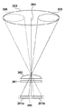
図3は、光学系1の異なる射出瞳から出る光束と単位画素200との関係を示しており、図2と同様の部分については、同じ符号を付している。
FIG. 3 shows the relationship between the luminous fluxes emitted from different exit pupils of the
図3に示すように、カラーフィルタ301とマイクロレンズ302とが、各々の単位画素200上に形成されている。レンズの射出瞳303を通過した光は、光軸304を中心として単位画素200に入射する。射出瞳303の一部の領域である瞳領域305を通過する光束は、マイクロレンズ302を通って、副画素aで受光される。一方、射出瞳303の他の一部の領域である瞳領域306を通過する光束は、マイクロレンズ302を通って、副画素bで受光される。したがって、副画素aと副画素bは、それぞれ、光学系1の射出瞳303の別々の瞳領域305、306の光を受光している。このように視差が異なる副画素aの出力信号(A像信号)と副画素bの出力信号(B像信号)を比較することで(撮像面)位相差方式の焦点検出が可能となる。
As shown in FIG. 3, a
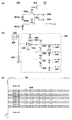
図4は、撮像素子3の回路構成を示している。画素領域PAには、単位画素200がp11〜pknのように行列状(n行×k列)に配置されている。ここで、単位画素200の構成を、図5(a)を用いて説明する。図5(a)は、撮像素子の単位画素の回路構成を示す図である。
FIG. 4 shows a circuit configuration of the
図5(a)において、前述した副画素a、bのPD(光電変換部)501a、501bに入射した光信号が、PD501a、501bによって光電変換され、露光量に応じた電荷がPD501a、501bに蓄積される。転送ゲート502a、502bのゲートに印加する信号txa、txbをそれぞれHighレベルにすることで、PD501a、501bに蓄積されている電荷がFD(フローティングディフュージョン)部503に転送される(電荷転送)。FD部503は、フローティングディフュージョンアンプ504(以下FDアンプと表す)のゲートに接続されており、PD501a、501bから転送されてきた電荷量がFDアンプ504によって電圧量に変換される。
In FIG. 5A, the optical signals incident on the PDs (photoelectric conversion units) 501a and 501b of the sub-pixels a and b described above are photoelectrically converted by the PDs 501a and 501b, and charges corresponding to the exposure amount are stored in the PDs 501a and 501b. Accumulated. By setting the signals txa and txb applied to the gates of the
FD部503をリセットするためのFDリセットスイッチ505のゲートに印加する信号resをHighレベルとすることにより、FD部503がリセットされる。また、PD501a、501bの電荷をリセットする場合には、信号resと信号txa、txbとを同時にHighレベルとする。これにより、転送ゲート502a、502b及びFDリセットスイッチ505の両方がON状態となり、FD部503経由でPD501a、501bがリセットされる。画素選択スイッチ506のゲートに印加する信号selをHighレベルとすることにより、FDアンプ504によって電圧に変換された画素信号が単位画素200の出力voutに出力される。
The
図4に示すように、垂直走査回路401は、前述の単位画素200の各スイッチを制御するres、txa、txb、selといった駆動信号を各単位画素200に供給する。これらの駆動信号res、txa、txb、selは、行毎において共通となっている。各単位画素200の出力voutは、列毎に垂直出力線402を介して列共通読出し回路403に接続されている。
As shown in FIG. 4, the
ここで、列共通読出し回路403の構成を、図5(b)を用いて説明する。
Here, the configuration of the column
垂直出力線402は、単位画素200の列毎に設けられ、1列分の単位画素200の出力voutが接続されている。垂直出力線402には電流源404が接続されており、電流源404と、垂直出力線402に接続された単位画素200のFDアンプ504とによってソースフォロワ回路が構成される。
The
図5(b)において、クランプ容量601はC1の容量を有しており、フィードバック容量602はC2の容量を有しており、演算増幅器603は、基準電源Vrefに接続された非反転入力端子を有している。スイッチ604はフィードバック容量602の両端をショートさせるためのものであり、スイッチ604は信号cfsによって制御される。
In FIG. 5B, the
転送スイッチ605〜608は、それぞれ単位画素200から読み出される信号を各信号保持容量609〜612に転送するためのものである。後述する読み出し動作によって、第1のS信号保持容量609には、副画素aから出力される画素信号Saが記憶される。また、第2のS信号保持容量611には、副画素aから出力される信号と副画素bから出力される信号とを合成(加算)した信号であるa/b合成信号Sabが記憶される。また、第1のN信号保持容量610及び第2のN信号保持容量612には、単位画素200のノイズ信号Nがそれぞれ記憶される。各信号保持容量609〜612は、それぞれ列共通読出し回路403の出力vsa、vna、vsb、vnbに接続されている。
The transfer switches 605 to 608 are for transferring the signals read from the
列共通読出し回路403の出力vsa、vnaには、それぞれ水平転送スイッチ405、406が接続されている。水平転送スイッチ405、406は、水平走査回路411の出力信号ha*(*は列番号)によって制御される。
Horizontal transfer switches 405 and 406 are connected to the outputs vsa and vna of the column
また、列共通読出し回路403の出力vsb、vnbには、それぞれ水平転送スイッチ407、408が接続されている。水平転送スイッチ407、408は、水平走査回路411の出力信号hb*(*は列番号)によって制御される。水平出力線409、410は差動増幅器414の入力に接続されており、差動増幅器414ではS信号とN信号の差分をとると同時に所定のゲインをかけ、最終的な出力信号を出力端子415へ出力する。
Further, horizontal transfer switches 407 and 408 are connected to the outputs vsb and vnb of the column
水平出力線リセットスイッチ412、413のゲートに印加する信号chresをHighにすると、水平出力線リセットスイッチ412、413がONとなり、各水平出力線409、410がリセット電圧Vchresにリセットされる。
When the signal chres applied to the gates of the horizontal output line reset switches 412 and 413 is set to High, the horizontal output line reset switches 412 and 413 are turned on and the
以下、A像信号の読み出し動作と、A像信号とB像信号の合成信号であるA+B像信号の読み出し動作について説明する。 Hereinafter, a read operation of the A image signal and a read operation of the A+B image signal which is a composite signal of the A image signal and the B image signal will be described.
図5(c)は、撮像素子3の画素領域PAに設定される焦点調節用の距離情報取得領域と被写体検出用の距離情報取得領域との関係を示している。測距枠620は、AF制御部8からの領域情報によって測距部6により設定される。
FIG. 5C shows the relationship between the distance information acquisition area for focus adjustment and the distance information acquisition area for subject detection that are set in the pixel area PA of the
k列×n行の画素で構成される画素領域PAにおいて、点線で示す領域が測距枠620である。斜線部で示す距離情報取得領域R1に含まれる単位画素の行(画素ライン)からは、A像信号及びA+B像信号が読み出され、画像の生成、焦点検出及び被写体検出に使用される。距離情報取得領域R1以外の領域R2に含まれる単位画素の行(画素ライン)からは、A像信号とB像信号の加算信号のみが読み出され、画像生成のみに使用される。
In the pixel area PA including pixels of k columns×n rows, the area indicated by the dotted line is the
なお、図5(c)に示すように、画素領域の垂直方向に複数の領域R1を設定した場合、各領域R1における単位画素200の行の数を互いに異ならせて設定してもよい。
Note that, as shown in FIG. 5C, when a plurality of regions R1 are set in the vertical direction of the pixel region, the number of rows of the
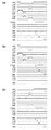
次に、撮像素子3の読み出し動作について図6(a)を用いて説明する。図6(a)は、前述の領域R2の各行に対して行われる読み出し動作のタイミングチャートである。
Next, the read operation of the
まず、信号cfsをHighレベルにしてスイッチ604をONすることにより、演算増幅器603をバッファ状態にする。次に、信号selをHighレベルにして単位画素の画素選択スイッチ506をONにする。その後、信号resをLowレベルにしてFDリセットスイッチ505をOFFにし、FD部503のリセットを開放する。
First, the signal cfs is set to the high level and the switch 604 is turned on to put the
続いて信号cfsをLowレベルに戻してスイッチ604をOFFにした後、信号tna、tnbをHighレベルにして、転送スイッチ606、608を介して第1のN信号保持容量610及び第2のN信号保持容量612にノイズ信号Nを記憶する。
Subsequently, the signal cfs is returned to the low level to turn off the switch 604, and then the signals tna and tnb are set to the high level, and the first N
次いで、信号tna、tnbをLowにし、転送スイッチ606、608をOFFにする。その後、信号tsbをHighレベルにして転送スイッチ607をONにすると共に、信号txa及びtxbをHighレベルにすることで転送ゲート502aと502bをONにする。この動作により、副画素aのPD501aに蓄積されていた電荷信号及び副画素bのPD501bに蓄積された電荷信号を合成した信号が、FDアンプ504、画素選択スイッチ506を介して垂直出力線402へ出力される。垂直出力線402の信号は、クランプ容量601の容量C1とフィードバック容量602の容量C2との容量比に応じたゲインで演算増幅器603により増幅され、転送スイッチ607を介して第2のS信号保持容量611へ記憶される(a/b合成信号Sab)。転送ゲート502a及び502bと、転送スイッチ607とを順次OFFにした後、信号resをHighレベルにしてFDリセットスイッチ505をONにし、FD部503をリセットする。
Next, the signals tna and tnb are set to Low, and the transfer switches 606 and 608 are turned off. After that, the signal tsb is set to the high level to turn on the
次に、水平走査回路411の出力hb1がHighレベルになることにより、水平転送スイッチ407、408がONされる。これにより、第2のS信号保持容量611、第2のN信号保持容量612の信号が水平出力線409、410と差動増幅器414を介して出力端子415に出力される。水平走査回路411は、各列の選択信号hb1、hb2、・・・、hbkを順次Highにすることにより、1行分のa/b合成信号(A+B像信号)を出力する。尚、信号hb1〜hbkによって各列の信号が読み出される間には、信号chresをHighレベルにすることで水平出力線リセットスイッチ412、413をONし、一旦、水平出力線409、410をリセット電圧Vchresのレベルにリセットする。
Next, the output hb1 of the
以上が、領域R2における単位画素の各行の読み出し動作である。これにより、A+B像信号が読み出されることになる。 The above is the read operation of each row of the unit pixel in the region R2. As a result, the A+B image signal is read out.
続いて、領域R1の各行の読み出し動作について図6(b)、図6(c)を用いて説明する。図6(b)は、A像信号が読み出されるまでの動作のタイミングチャートである。信号cfsをHighレベルにすることから始まり、信号tna、tnbをLowにして第1のN信号保持容量610及び第2のN信号保持容量612にN信号を記憶するまでの動作は、図6(a)で説明した動作と同様である。
Next, the read operation of each row of the region R1 will be described with reference to FIGS. 6B and 6C. FIG. 6B is a timing chart of the operation until the A image signal is read. The operation from the setting of the signal cfs to the High level to the setting of the signals tna and tnb to Low and storing the N signal in the first N
ノイズ信号Nの記憶が終了すると、信号tsaをHighレベルにして転送スイッチ605をONにすると共に、信号txaをHighレベルにすることで転送ゲート502aをONする。このような動作によって、副画素aのPD501aに蓄積されていた信号が、FDアンプ504及び画素選択スイッチ506を介して垂直出力線402へ出力される。垂直出力線402の信号は、演算増幅器603において、クランプ容量601の容量C1とフィードバック容量602の容量C2との容量比に応じたゲインで増幅され、転送スイッチ605を介して第1のS信号保持容量609に記憶される(画素信号Sa)。
When the storage of the noise signal N is completed, the signal tsa is set to the high level to turn on the
次に、水平走査回路411の出力ha1がHighレベルになることにより、水平転送スイッチ405、406がONされる。これにより、第1のS信号保持容量609、第1のN信号保持容量610の信号が水平出力線409、410と差動増幅器414とを介して出力端子415に出力される。水平走査回路411は、各列の選択信号ha1、ha2、・・・、hakを順次Highにすることにより、1行分の副画素aの信号(A像信号)を出力する。
Next, when the output ha1 of the
信号resはLowレベルのままで、信号selはHighレベルのままで、A像信号の読み出しを終了する。これにより、FD部503上のA像信号はリセットされず保持されることになる。
The signal res remains at the low level and the signal sel remains at the high level, and the reading of the A image signal is completed. As a result, the A image signal on the
A像信号の読み出しが終了すると、続けて図6(c)に示すA+B像信号の読み出し動作へと移る。信号tsbをHighレベルにして転送スイッチ607をONすると共に、信号txa及びtxbをHighレベルにすることで転送ゲート502aと502bとをONにする。このような動作により、副画素bのPD501bに蓄積されていた信号がFD部503に保持されていた副画素aの信号と加算され、加算された信号がFDアンプ504、画素選択スイッチ506を介して垂直出力線402へ出力される。これ以降の部分は、図6(a)を用いて説明した領域R2の動作と同じである。
When the reading of the A image signal is completed, the operation of reading the A+B image signal shown in FIG. The signal tsb is set to the high level to turn on the
以上により、領域R1における各行の読み出し動作が終了する。これにより、領域R1では、A像信号の読み出しとA+B像信号の読み出しが行われ、A像信号とA+B像信号が順次読み出されることになる。 As described above, the read operation of each row in the region R1 is completed. As a result, in the region R1, the A image signal and the A+B image signal are read, and the A image signal and the A+B image signal are sequentially read.
<撮影動作>
次に、上述した構成を有する撮像装置100による画像撮影時の動作について説明する。
<Shooting operation>
Next, an operation at the time of image capturing by the
まず、光学系1は、光学系駆動部2からの駆動信号により、絞りとレンズを駆動して、適正な明るさに設定された被写体像を撮像素子3の受光面に結像させる。撮像素子3は、撮像センサ駆動部4からの駆動パルスにより駆動され、被写体像を光電変換により電気信号に変換して画像信号として出力する。
First, the
撮像センサ駆動部4は、AF制御部8からの領域情報に応じた駆動パルスにより、上述した読み出し動作によって領域R1からA像信号の読み出しとA+B像信号の読み出しを行い、領域R2からA+B像信号の読み出しを行う。このようにA像信号を一部の領域で読み出すことで処理負荷を軽減している。さらに、AF制御部8は、A像信号を読み出した領域R1では、A+B像信号からA像信号を差し引くことでB像信号を取得し、A像信号とB像信号を用いてAF制御を行う。なお、領域R1からA像信号とB像信号を個別に読み出すと共に、領域R1以外の領域R2からA+B像信号を読み出すことでAF制御を行ってもよい。
The image
コントラストAF評価値算出部5は撮像素子3からの画像信号とAF制御部8からの測距枠情報に基づき、測距枠内のコントラスト評価値を算出し、AF制御部8へ出力する。この場合、コントラストAF評価値算出部5は、AF制御部8からの領域情報に基づき、A像信号とB像信号を加算し、距離情報取得領域R1以外の領域R2から読み出したA+B像信号と同じ形式にしてからコントラスト評価値を算出する。
The contrast AF evaluation
ここで、コントラストAFの概要について説明する。コントラストAF評価値算出部5は、A像信号から得られる第1焦点検出信号と、B像信号から得られる第2焦点検出信号を相対的に瞳分割方向にシフトさせ、加算してシフト加算信号を生成し、生成されたシフト加算信号からコントラスト評価値を算出する。
Here, the outline of the contrast AF will be described. The contrast AF evaluation
k番目の第1焦点検出信号をA(k)、第2焦点検出信号をB(k)、距離情報取得領域R1に対応する番号kの範囲をWとし、シフト処理によるシフト量をs1、シフト量s1のシフト範囲をτ1として、コントラスト評価値RFCONは、下記式により算出される。 The k-th first focus detection signal is A(k), the second focus detection signal is B(k), the range of the number k corresponding to the distance information acquisition region R1 is W, the shift amount by the shift process is s1, the shift The contrast evaluation value RFCON is calculated by the following formula, where τ1 is the shift range of the amount s1.
![]()
![]()
シフト量s1のシフト処理により、k番目の第1焦点検出信号A(k)とk−s1番目の第2焦点検出信号B(k−s1)を対応させて加算してシフト加算信号が生成され、シフト加算信号からコントラスト評価値RFCON(s1)が算出される。 By the shift processing of the shift amount s1, the kth first focus detection signal A(k) and the k−s1th second focus detection signal B(k−s1) are added in association with each other to generate a shift addition signal. , The contrast evaluation value RFCON(s1) is calculated from the shift addition signal.
測距部6は、AF制御部8からの領域情報に基づき、撮像センサ駆動部4により可変制御されるAF制御用の距離情報取得領域と被写体検出用の距離情報取得領域から読み出したA像信号、およびA+B像信号からA像信号を減算して得られるB像信号を用いて被写体の距離情報(第1の深さ情報、第2の深さ情報)を算出する。なお、本実施形態では、距離情報は(撮像面)位相差方式のAFを行うための位相差情報(デフォーカス量)である。
Based on the area information from the
ここで、位相差AFの概要について説明する。測距部6は、A像信号から得られる第1焦点検出信号と、B像信号から得られる第2焦点検出信号を相対的に瞳分割方向にシフトさせ、信号の一致度を表す相関量を算出する。k番目の第1焦点検出信号をA(k)、第2焦点検出信号をB(k)、距離情報取得領域R1に対応する番号kの範囲をWとし、シフト処理によるシフト量をs2、シフト量s2のシフト範囲をτ2として、相関量CORは、下記式により算出される。 Here, the outline of the phase difference AF will be described. Distance measuring unit 6, a first focus detection signal obtained from the A image signal, shifts the second focus detection signal obtained from the image signal B relative pupil division direction, the correlation value representing the degree of coincidence of the signal To calculate. The k-th first focus detection signal is A(k), the second focus detection signal is B(k), the range of the number k corresponding to the distance information acquisition region R1 is W, the shift amount by the shift process is s2, the shift The correlation amount COR is calculated by the following equation, where the shift range of the amount s2 is τ2.

シフト量s2のシフト処理により、k番目の第1焦点検出信号A(k)とk−s2番目の第2焦点検出信号B(k−s2)を対応させ減算し、シフト減算信号を生成し、距離情報取得領域に対応する範囲W内で番号kの和をとり、相関量COR(s2)を算出する。そして、相関量から、サブピクセル演算により、相関量が最小値となる実数値のシフト量を算出して像ずれ量p1とする。像ずれ量p1に、焦点検出領域の像高と、撮像レンズ(結像光学系)のF値、射出瞳距離に応じた第1の変換係数K1をかけて、デフォーカス量を検出する。 By the shift processing of the shift amount s2, the kth first focus detection signal A(k) and the k−s2th second focus detection signal B(k−s2) are subtracted in association with each other to generate a shift subtraction signal, The sum of the numbers k is calculated within the range W corresponding to the distance information acquisition area, and the correlation amount COR(s2) is calculated. Then, from the correlation amount, a sub-pixel calculation is performed to calculate a real-value shift amount that minimizes the correlation amount to obtain an image shift amount p1. The defocus amount is detected by multiplying the image shift amount p1 by the image height of the focus detection region, the F value of the imaging lens (imaging optical system), and the first conversion coefficient K1 according to the exit pupil distance.
なお、本実施形態では、測距部6が、異なる視差のA像信号とB像信号から距離情報を算出する例を示すが、被写体検出用の情報としては、例えば、「距離」に換算されない「深さに対応する情報」としてもよい。「深さに対応する情報」は、例えば、「距離」に換算されるまでの過程で生成されるA像信号とB像信号の「視差量(像ずれ量)」の情報、「デフォーカス量」の情報、「被写体距離」の情報のうちのいずれの形態であってもよい。そして、本実施形態では、「深さに対応する情報」のうちの「被写体距離」を、被写体検出用として画面全体に分散させて取得する。なお、被写体検出用の「深さに対応する情報」は画像に関連付けて記録してもよい。 In the present embodiment, the distance measuring unit 6 shows an example in which the distance information is calculated from the A image signal and the B image signal of different parallax, but the information for subject detection is not converted into, for example, “distance”. It may be "information corresponding to the depth". The “information corresponding to the depth” is, for example, the information of the “parallax amount (image shift amount)” of the A image signal and the B image signal generated in the process of being converted into the “distance”, and the “defocus amount”. “,” or “subject distance” information. Then, in the present embodiment, the “subject distance” of the “information corresponding to the depth” is acquired by being dispersed over the entire screen for subject detection. The "information corresponding to the depth" for subject detection may be recorded in association with the image.
本発明は、画像における被写体の深さに対応する情報としてさまざまな実施形態での適用が可能である。つまり、被写体の深さに対応するデータが示す情報(深さ情報)は、画像内における撮像装置から被写体までの被写体距離を直接的に表すか、または画像内の被写体の被写体距離や深さの相対関係を表す情報であればよい。 The present invention can be applied in various embodiments as information corresponding to the depth of a subject in an image. That is, the information (depth information) indicated by the data corresponding to the depth of the object directly represents the object distance from the image pickup device to the object in the image, or the object distance or depth of the object in the image. Any information can be used as long as it represents the relative relationship.
具体的には、撮像素子3は、光学系1の異なる瞳領域を通過する一対の光束が光学像としてそれぞれ結像したものを、対をなす画像信号として複数の光電変換部から出力することができる。対をなす画像信号間の相関演算によって各領域の像ずれ量が算出され、像ずれ量の分布を表す像ずれマップが算出される。あるいはさらに像ずれ量がデフォーカス量に換算され、デフォーカス量の分布(撮像画像の2次元平面上の分布)を表すデフォーカスマップが生成される。このデフォーカス量を光学系1や撮像素子3の条件に基づいて被写体距離に換算すると、被写体距離の分布を表す距離マップデータが得られる。
Specifically, the
このように、本実施形態では、測距部6は、像ずれマップデータ、デフォーカスマップデータ、あるいはデフォーカス量から変換される被写体距離の距離マップデータを取得すればよい。なお、各マップデータの各データはブロック単位で持っていてもよいし、画素単位で持っていてもよい。この場合、通常の画像データのように最小単位ごとに8ビット程度ビット数を割り当て、距離画像として画像処理や表示、記録などを画像処理と同様に行ってもよい。 As described above, in the present embodiment, the distance measuring unit 6 may acquire the image shift map data, the defocus map data, or the distance map data of the subject distance converted from the defocus amount. It should be noted that each data of each map data may be held in block units or in pixel units. In this case, a bit number of about 8 bits may be assigned to each minimum unit like normal image data, and image processing, display, recording, etc. may be performed as a distance image in the same manner as image processing.
被写体追尾部7は、撮像素子3からの画像信号とAF制御部8からの距離情報とに基づいて被写体を検出し、検出された被写体から主被写体を特定し、その位置や大きさ(サイズ)に関する被写体情報を、AF制御部8に出力する。被写体追尾部7が特定の人物の顔を主被写体(主顔)として追尾する場合、画面のより中央に近い位置にある顔を主顔に設定し、主顔の動きベクトルや色、大きさから主顔の移動先を検出する。そして、被写体追尾部7は、主顔の距離情報及び主顔周辺の被写体の距離情報に基づいて主顔の追尾を行い、他の被写体と主顔とがすれ違った場合などに主顔の判別を行う。
The subject tracking unit 7 detects the subject based on the image signal from the
AF制御部8は、コントラストAF評価値算出部5からのコントラスト評価値と、測距部6からの距離情報とに基づき、撮像センサ駆動部4へ領域情報を出力する。
The
また、AF制御部8は、コントラスト方式でAFを行う場合はコントラストAF評価値算出部5からのコントラスト評価値に基づき合焦位置(コントラスト評価値が最大となるピーク位置)を検出し、主被写体を合焦状態にするための光学系駆動情報を光学系駆動部2へ出力する。また、AF制御部8は、位相差方式でAFを行う場合は測距部6からの(相関量が最小となる像ずれ量やデフォーカス量に対応する)距離情報に基づき合焦位置を検出し、主被写体を合焦状態にするための光学系駆動情報を光学系駆動部2へ出力する。なお、AF制御部8は、位相差方式のAFを行って(測距部6からの距離情報を用いて)主被写体を合焦状態に近づけ、さらにコントラスト方式のAFを行って(コントラスト評価値を用いて)主被写体を合焦状態にするような制御を行ってもよい。すなわち、AF制御部8は、コントラストAF評価値算出部5からのコントラスト評価値と測距部6からの距離情報の少なくともいずれかを用いて主被写体を合焦状態にするような制御を行ってもよい。
Further, when performing AF by the contrast method, the
信号処理部9は、撮像素子3からの画像信号を輝度信号と色差信号に変換した画像データを生成して記録部10や表示部11に出力する。記録部10及び表示部11は、信号処理部9により生成された画像データの記録・表示を行う。
The
<AF制御部8における光学系駆動情報及び領域情報の算出処理>
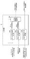
次に、図7を参照して、AF制御部8による光学系駆動情報及び領域情報の算出処理について説明する。
<Calculation process of optical system drive information and area information in
Next, the calculation processing of the optical system drive information and the area information by the
まず、AF制御部8による光学系駆動部2に出力する光学系駆動情報の算出処理を説明する。
First, the calculation processing of the optical system drive information output to the optical
図7において、第1の光学系駆動量算出部700は、コントラストAF評価値算出部5からのコントラスト評価値に基づき、いわゆる山登り方式によって第1の光学系駆動量を算出する。第2の光学系駆動量算出部701は、測距部6からの距離情報に基づき、第2の光学系駆動量を算出する。光学系駆動量加算部702は、後述するコントラスト評価値に基づいて第1及び第2の光学系駆動量を重み付けして加算し、光学系駆動部2に出力する光学系駆動情報を算出する。
In FIG. 7, the first optical system drive
上述したように、コントラストAFは、いわゆる山登り方式であり、フォーカスレンズを移動させながら、コントラスト評価値が大きくなるようにレンズ駆動量を算出することから合焦までに時間がかかる。一方で、位相差方式のAFは被写体までの距離情報が得られることから大ボケの場合であっても精度の高いレンズ駆動量が算出できる。このため、合焦付近までのレンズの駆動は高速で行えるが、合焦付近での焦点調節精度はコントラストAFに比べて低くなる。 As described above, the contrast AF is a so-called hill-climbing method, and it takes time from focusing to moving the focus lens and calculating the lens driving amount so that the contrast evaluation value becomes large, until focusing. On the other hand, in the phase difference AF, since the distance information to the subject is obtained, the lens drive amount can be calculated with high accuracy even in the case of large blur. For this reason, the lens can be driven at high speed up to near focus, but the focus adjustment accuracy near focus is lower than in contrast AF.
そこで、本実施形態では、光学系駆動部2は、図8に示すようにコントラスト評価値に応じて第1の光学系駆動量と第2の光学系駆動量に重み付けをする。具体的には、コントラスト評価値が大きいほど第1の光学系駆動量の重み付けが大きくなり、コントラスト評価値が小さいほど第2の光学系駆動量の重み付けが小さくなるように係数αを設定し、例えば以下の式を用いて加算する。
Therefore, in the present embodiment, the optical
MV=α×Caf+(1−α)×R*Daf
ここで、αは重み付け係数、Cafは第1の光学系駆動量、Dafは第2の光学系駆動量である。
MV=α×Caf+(1-α)×R*Daf
Here, α is a weighting coefficient, Caf is a first optical system drive amount, and Daf is a second optical system drive amount.
次に、AF制御部8による撮像センサ駆動部4に出力する領域情報の算出処理を説明する。
Next, the calculation processing of the area information output to the image
図7の距離情報取得領域設定部703は、コントラストAF評価値算出部5からのコントラスト評価値と、被写体追尾部7からの主被写体の被写体情報(位置、大きさ)から領域情報を設定する。
The distance information acquisition
<AF制御部の動作>
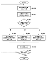
次に、図9を参照して、撮影動作におけるAF制御時に、AF制御部8の距離情報取得領域設定部703が撮像センサ駆動部4へ領域情報を出力する処理について説明する。
<Operation of AF control unit>
Next, with reference to FIG. 9, a process in which the distance information acquisition
S900では、距離情報取得領域設定部(以下、領域設定部)703は、コントラストAF評価値算出部5からコントラスト評価値を取得する。
In S900, the distance information acquisition area setting unit (hereinafter, area setting unit) 703 acquires the contrast evaluation value from the contrast AF evaluation
S901では、領域設定部703は、被写体追尾部7から主被写体の被写体情報(位置、大きさ)を取得する。
In step S<b>901, the
S902では、領域設定部703は、S901で取得したコントラスト評価値に基づいてAFの状態を判定する。領域設定部703は、閾値Th1、Th2(Th1<Th2)を用いて、コントラスト評価値が閾値Th1より小さい場合は大ボケと判定し、コントラスト評価値が閾値Th1より大きく、閾値Th2より小さい場合は中ボケと判定し、コントラスト評価値が閾値Th2より大きい場合は合焦と判定する。そして、AF状態が大ボケと判定された場合はS903へ、中ボケと判定された場合はS904へ、合焦と判定された場合はS905へ処理を進める。
In step S902, the
ここで、前述したようにコントラスト評価値が大きいほど第1の光学系駆動量の重み付けが大きくなり、コントラスト評価値が小さいほど第2の光学系駆動量の重み付けが小さくなるように重み付け係数αが設定される。したがって、コントラスト評価値が大きい場合には第2の光学系駆動量の算出精度を落としてもAF制御の精度低下は小さくなる。換言すると、コントラスト評価値が小さい場合には第2の光学系駆動量の算出精度を低下させてはならない。 Here, as described above, the weighting coefficient α is set such that the weighting of the first optical system drive amount increases as the contrast evaluation value increases, and the weighting of the second optical system drive amount decreases as the contrast evaluation value decreases. Is set. Therefore, when the contrast evaluation value is large, even if the calculation accuracy of the second optical system drive amount is lowered, the accuracy reduction of AF control is small. In other words, when the contrast evaluation value is small, the calculation accuracy of the second optical system drive amount should not be reduced.
また、被写体追尾部7においては、被写体検出用の距離マップは、主被写体の判別ができないくらいコントラスト評価値が小さい場合には不要であり、主被写体が判別できる程度にコントラスト評価値が大きい場合に必要となる。そこで、本実施形態では、コントラスト評価値に応じて、AF制御用の距離情報取得領域が設定されるフレームの頻度と、被写体検出用の距離情報取得領域が設定されるフレームの頻度を可変に制御し、AF制御の精度と被写体追尾の精度を両立できるような距離マップを取得可能としている。 Further, in the subject tracking section 7, the distance map for subject detection is unnecessary when the contrast evaluation value is so small that the main subject cannot be discriminated, and when the contrast evaluation value is large enough to discriminate the main subject. Will be required. Therefore, in the present embodiment, the frequency of frames in which the distance information acquisition area for AF control is set and the frequency of frames in which the distance information acquisition area for subject detection is set are variably controlled according to the contrast evaluation value. However, it is possible to obtain a distance map that can achieve both AF control accuracy and object tracking accuracy.
ここで、図10を参照しながら、図9のS903〜S905における距離情報取得領域が設定される頻度を切り替える制御について詳細に説明する。なお、図10の(a)、(b)、(c)において、(a−1)〜(a−4)、(b−1)〜(b−4)、(c−1)〜(c−4)は、撮像された画像信号の各フレームを時系列的に示したものである。また、図10の(a)、(b)、(c)において、1000は主被写体、1001は主被写体以外の被写体、1002はAF制御用の距離情報取得領域を例示している。また、1003は被写体検出用の距離情報取得領域をそれぞれ示している。また、図10において、(a)は大ボケ状態(S903)での領域設定例、(b)は中ボケ状態(S904)での領域設定例、(c)は合焦状態(S905)での領域設定例をそれぞれ例示している。
Here, the control for switching the frequency of setting the distance information acquisition area in S903 to S905 of FIG. 9 will be described in detail with reference to FIG. In addition, in (a), (b), and (c) of FIG. 10, (a-1) to (a-4), (b-1) to (b-4), (c-1) to (c). -4) shows each frame of the captured image signal in time series. In addition, in FIGS. 10A, 10B, and 10C,
S903の大ボケ状態の場合には、領域設定部703は、図10(a)のようにAF制御用の距離情報取得領域1002が設定されるフレームの頻度が最も高くなるように領域設定を行う。
In the case of the large blurring state in S903, the
S904の中ボケ状態の場合には、領域設定部703は、図10(b)のようにAF制御用の距離情報取得領域1002が設定されるフレームの頻度が中くらいになるように領域設定を行う。図10(b)の中ボケ状態では、図10(a)の大ボケ状態と比べてAF制御用の距離情報取得領域1002が設定されるフレームの頻度を低くすると共に、被写体検出用の距離情報取得領域が設定されるフレームの頻度を高くする。
In the case of the middle-blur state in S904, the
S905は合焦状態なので、領域設定部703は、図10(c)のようにAF制御用の距離情報取得領域が設定されるフレームの頻度が低くなるように領域設定を行う。図10(c)の合焦状態では、図10(b)の中ボケ状態と比べてさらにAF制御用の距離情報取得領域1002が設定されるフレームの頻度を低くすると共に、被写体検出用の距離情報取得領域が設定されるフレームの頻度を高くする。例えば、図10(c)のようにAF制御用の距離情報取得領域1002が設定されるフレームの割合と被写体検出用の距離情報取得領域が設定されるフレームの割合が同じとなる。
Since the focus state is set in step S905, the
S906では、領域設定部703は、S903からS905で設定されたAF制御用の距離情報取得領域の設定頻度に応じて領域情報を算出し、撮像センサ駆動部4へ出力する。
In step S906, the
S907では、領域設定部703は、操作部12を介してユーザから撮影終了が指示されるなどをトリガーとして、撮影動作が終了したか否かを判定し、終了と判定されるまでS900からの処理を繰り返す。
In step S<b>907, the
本実施形態によれば、画像撮影中のAF制御時に、AF制御用の距離情報取得領域が設定されるフレームの割合と、被写体検出用の距離情報取得領域が設定されるフレームの割合を、コントラスト評価値に応じて可変に制御している。このようにすることで、AF制御の精度と主被写体追尾の精度とを両立することができるようになる。 According to this embodiment, during AF control during image capturing, the ratio of the frames in which the distance information acquisition area for AF control is set and the ratio of the frames in which the distance information acquisition area for subject detection is set are It is variably controlled according to the evaluation value. By doing so, it is possible to achieve both the accuracy of AF control and the accuracy of main subject tracking.
なお、上述した実施形態では、AF制御用の距離情報取得領域を主被写体の被写体情報(位置、大きさ)に基づいて設定したが、AFモードやユーザが指定した被写体に合わせて設定してもよい。また、AFの状態をコントラスト評価値に基づいて判定しているが、測距部6により位相差方式で判定してもよい。 In the above embodiment, the distance information acquisition area for AF control is set based on the subject information (position, size) of the main subject, but it may be set according to the AF mode or the subject designated by the user. Good. Although the AF state is determined based on the contrast evaluation value, the distance measuring unit 6 may determine the AF state by the phase difference method.
[実施形態2]次に、実施形態2について説明する。 [Second Embodiment] Next, a second embodiment will be described.
実施形態1では、領域設定部703が、コントラスト評価値に基づいてAF制御用の距離情報取得領域が設定されるフレームの割合と、被写体検出用の距離情報取得領域が設定されるフレームの割合を制御していた。これに対して、実施形態2では、図11の距離情報取得領域設定部(以下、領域設定部)1103は、主被写体以外の被写体の数に基づいてAF制御用の距離情報取得領域と被写体検出用の距離情報取得領域の割合を制御する。
In the first embodiment, the
なお、実施形態2において、実施形態1と同様の要素には同一の符号付して説明を省略する。実施形態1と異なる点は、被写体追尾部7が撮像素子3からの画像信号と測距部6からの距離情報とに基づき、撮像画像中の被写体の数を検出し、AF制御部8に出力する点と、AF制御部8が被写体追尾部7からの被写体の数に基づいてAF制御用の距離情報取得領域と被写体検出用の距離情報取得領域の割合を制御する点である。
In the second embodiment, the same elements as those in the first embodiment are designated by the same reference numerals and the description thereof will be omitted. The difference from the first embodiment is that the subject tracking unit 7 detects the number of subjects in the captured image based on the image signal from the
まず、図12を参照して、撮影動作におけるAF制御時に、AF制御部8の領域設定部1103が撮像センサ駆動部4へ領域情報を出力する処理について説明する。
First, with reference to FIG. 12, a process in which the
S1200では、領域設定部1103は、被写体追尾部7から主被写体の被写体情報(位置、大きさ)を取得する。
In step S1200, the
S1201では、領域設定部1103は、被写体追尾部7から主被写体以外の被写体の数を取得する。
In step S1201, the
S1202では、領域設定部1103は、S1201で取得した主被写体以外の被写体の数が多いか、少ないか、中くらいかを判定する。領域設定部1103は、閾値Th3、Th4(Th3<Th4)を用いて、主被写体以外の被写体の数が閾値Th3より小さい場合は少ないと判定し、主被写体以外の被写体の数が閾値Th3より大きく、閾値Th4より小さい場合は中くらいと判定し、主被写体以外の被写体の数が閾値Th4より大きい場合は多いと判定する。そして、主被写体以外の被写体の数が少ないと判定された場合はS1203へ、中くらいと判定された場合はS1204へ、多いと判定された場合はS1205へ処理を進める。
In S1202, the
本実施形態において主被写体以外の被写体の数を判定条件としているのは、主被写体以外の被写体の数が多いほど、主被写体の前をそれ以外の被写体がすれ違う可能性が高くなるため、距離情報を用いた主被写体の判別が必要となる可能性が高くなるからである。 In the present embodiment, the number of subjects other than the main subject is used as the determination condition because the greater the number of subjects other than the main subject, the higher the possibility that another subject will pass in front of the main subject. This is because there is a high possibility that the main subject needs to be discriminated using.
S1203では、領域設定部1103は、主被写体以外の被写体の数が多い場合には、図10(c)と同様に、AF制御用の距離情報取得領域1002が設定されるフレームの頻度を低くし、被写体検出用の距離情報取得領域が設定されるフレームの頻度が高くなるように領域設定を行う。
In step S1203, when the number of subjects other than the main subject is large, the
S1204では、領域設定部1103は、主被写体以外の被写体の数が中くらいの場合には、図10(b)と同様に、図10(c)と比べてAF制御用の距離情報取得領域1002が設定されるフレームの頻度を高くするが、図10(a)よりも低くなるように領域設定を行う。
In step S1204, when the number of subjects other than the main subject is medium, the
S1205では、領域設定部1103は、主被写体以外の被写体の数が少ない場合には、図10(a)と同様に、AF制御用の距離情報取得領域1002が設定されるフレームの頻度がさらに高くなるように領域設定を行う。
In step S1205, when the number of subjects other than the main subject is small, the
S1206では、領域設定部1103は、S1203〜S1205で設定されたAF制御用の距離情報取得領域の設定頻度に応じて領域情報を算出し、撮像センサ駆動部4へ出力する。
In step S1206, the
S1207では、領域設定部1103は、操作部12を介してユーザから撮影終了が指示されるなどをトリガーとして、撮影動作が終了したか否かを判定し、終了と判定されるまでS1200からの処理を繰り返す。
In step S1207, the
本実施形態によれば、画像撮影中のAF制御時に、AF制御用の距離情報取得領域が設定されるフレームの割合と、被写体検出用の距離情報取得領域が設定されるフレームの割合とを主被写体以外の被写体の数に応じて可変に制御している。このようにすることで、AF制御の精度と主被写体追尾の精度とを両立することができるようになる。 According to this embodiment, during AF control during image capturing, the ratio of the frames in which the distance information acquisition area for AF control is set and the ratio of the frames in which the distance information acquisition area for subject detection is set are mainly set. It is variably controlled according to the number of subjects other than the subject. By doing so, it is possible to achieve both the accuracy of AF control and the accuracy of main subject tracking.
なお、上述した実施形態では、AF制御用の距離情報取得領域を主被写体以外の被写体の数に基づいて設定したが、主被写体以外の被写体の動きベクトルを検出し、主被写体の前をそれ以外の被写体がすれ違う可能性が高いと判定した場合にはAF制御用の距離情報取得領域の割合を低くし、すれ違う可能性が低いと判定した場合には高くしてもよい。 In the above-described embodiment, the distance information acquisition area for AF control is set based on the number of subjects other than the main subject. However, the motion vector of the subject other than the main subject is detected, and the area in front of the main subject is other than that. When it is determined that there is a high possibility that the subjects pass each other, the ratio of the distance information acquisition region for AF control may be reduced, and when it is determined that the possibility of passing each other is low, the ratio may be increased.
[実施形態3]次に、実施形態3について説明する。 [Third Embodiment] Next, a third embodiment will be described.
実施形態1では、領域設定部703が、コントラスト評価値に基づいてAF制御用の距離情報取得領域が設定されるフレームの割合と、被写体検出用の距離情報取得領域が設定されるフレームの割合を制御していた。これに対して、実施形態3では、領域設定部703は、コントラスト評価値に基づいてフレーム内のAF制御用の距離情報取得領域の優先度を設定する。そして、領域設定部703は、設定された優先度に応じた割合でフレーム内に配置されるAF制御用の距離情報取得領域と被写体検出用の距離情報取得領域の割合を制御する。
In the first embodiment, the
なお、実施形態3において、実施形態1と同様の要素には同一の符号付して説明を省略する。 In the third embodiment, the same elements as those in the first embodiment are designated by the same reference numerals and the description thereof will be omitted.
以下、図13を参照して、撮影動作におけるAF制御時に、AF制御部8の領域設定部703が撮像センサ駆動部4へ領域情報を出力する処理について説明する。なお、図13のS1300〜S1302は、図9のS900〜S902と同様であるため説明を省略する。
Hereinafter, with reference to FIG. 13, a process in which the
ここで、図14を参照しながら、図13のS1303〜S1305における距離情報取得領域の優先度の設定処理について詳細に説明する。 Here, the setting process of the priority of the distance information acquisition region in S1303 to S1305 of FIG. 13 will be described in detail with reference to FIG.
図14において、1400は主被写体、1401は主被写体以外の被写体、1402はAF制御用の距離情報取得領域を例示している。また、1403は被写体検出用の距離情報取得領域を例示している。また、図14において、(a)は大ボケ状態(S1303)での領域設定例、(b)は中ボケ状態(S1304)での領域設定例、(c)は合焦状態(S1305)での領域設定例をそれぞれ例示している。
In FIG. 14,
S1303の大ボケ状態の場合には、領域設定部703は、AF制御用の距離情報取得領域1402の優先度が高くなるように領域設定を行う。これにより、図14(a)のようにフレーム内に配置されるAF制御用の距離情報取得領域1402の割合が大きくなり、AF制御用の距離情報取得領域1402が広くなる。
In the case of the large blurring state in S1303, the
S1304の中ボケ状態の場合には、領域設定部703は、AF制御用の距離情報取得領域1402の優先度が中くらいになるように領域設定を行う。図14(b)の中ボケ状態では、図14(a)の大ボケ状態と比べてフレーム内に配置されるAF制御用の距離情報取得領域1402の割合が小さくなるが、被写体検出用の距離情報取得領域1403が比較的狭いながらも画面全体に離散的に設定される。
In the case of the medium-blur state in S1304, the
S1305は合焦状態なので、領域設定部703は、AF制御用の距離情報取得領域の優先度が低くなるように領域設定を行う。図14(c)の合焦状態では、図14(b)の中ボケ状態と比べてさらにフレーム内のAF制御用の距離情報取得領域1402の割合が小さくなるが、被写体検出用の距離情報取得領域1403が比較的広くなるように画面全体に離散的に設定される。
Since the focus state is set in S1305, the
S1306では、領域設定部703は、S1303〜S1305で設定されたAF制御用の距離情報取得領域の優先度に応じて領域情報を算出し、撮像センサ駆動部4へ出力する。
In step S1306, the
S1307では、領域設定部703は、操作部12を介してユーザから撮影終了が指示されるなどをトリガーとして、撮影動作が終了したか否かを判定し、終了と判定されるまでS1300からの処理を繰り返す。
In step S1307, the
本実施形態によれば、画像撮影中のAF制御時に、AF状態に応じて、フレーム内に配置されるAF制御用の距離情報取得領域と被写体検出用の距離情報取得領域の割合を制御している。このようにすることで、AF制御の精度と主被写体追尾の精度とを両立することができるようになる。 According to the present embodiment, during AF control during image capturing, the ratio of the distance information acquisition area for AF control and the distance information acquisition area for subject detection arranged in the frame is controlled according to the AF state. There is. By doing so, it is possible to achieve both the accuracy of AF control and the accuracy of main subject tracking.
なお、上述した実施形態では、AF制御用の距離情報取得領域を主被写体の被写体情報(位置、大きさ)に基づいて設定したが、AFモードやユーザが指定した被写体に合わせて設定してもよい。また、AFの状態をコントラスト評価値に基づいて判定しているが、測距部6により位相差方式で判定してもよい。 In the above embodiment, the distance information acquisition area for AF control is set based on the subject information (position, size) of the main subject, but it may be set according to the AF mode or the subject designated by the user. Good. Although the AF state is determined based on the contrast evaluation value, the distance measuring unit 6 may determine the AF state by the phase difference method.
[実施形態4]次に、実施形態4について説明する。 Fourth Embodiment Next, a fourth embodiment will be described.
実施形態2では、領域設定部1103が、主被写体以外の被写体の数に基づいてAF制御用の距離情報取得領域と被写体検出用の距離情報取得領域の割合を制御していた。これに対して、実施形態4では、領域設定部1103が、主被写体以外の被写体の数に基づいてフレーム内のAF制御用の距離情報取得領域の優先度を設定する。そして、領域設定部1103は、設定された優先度に応じた割合でフレーム内に配置されるAF制御用の距離情報取得領域と被写体検出用の距離情報取得領域の割合を制御する。
In the second embodiment, the
なお、実施形態4において、実施形態2と同様の要素には同一の符号付して説明を省略する。 In the fourth embodiment, the same elements as those in the second embodiment will be assigned the same reference numerals and explanations thereof will be omitted.
以下、図15を参照して、撮影動作におけるAF制御時に、AF制御部8の領域設定部1103が撮像センサ駆動部4へ領域情報を出力する処理について説明する。なお、図15のS1500〜S1502は、図12のS1200〜S1202と同様であるため説明を省略する。
Hereinafter, with reference to FIG. 15, a process in which the
S1502では、領域設定部1103は、S1501で取得した主被写体以外の被写体の数が多いか、少ないか、中くらいかを判定する。領域設定部1103は、閾値Th3、Th4(Th3<Th4)を用いて、主被写体以外の被写体の数が閾値Th3より小さい場合は少ないと判定し、主被写体以外の被写体の数が閾値Th3より大きく、閾値Th4より小さい場合は中くらいと判定し、主被写体以外の被写体の数が閾値Th4より大きい場合は多いと判定する。そして、主被写体以外の被写体の数が少ないと判定された場合はS1503へ、中くらいと判定された場合はS1504へ、多いと判定された場合はS1505へ処理を進める。
In S1502, the
本実施形態において主被写体以外の被写体の数を判定しているのは、主被写体以外の被写体の数が多いほど、主被写体の前をそれ以外の被写体がすれ違う可能性が高くなるため、距離情報を用いた主被写体の判別が必要となる可能性が高くなるからである。 The number of subjects other than the main subject is determined in the present embodiment because the greater the number of subjects other than the main subject, the higher the possibility that other subjects will pass in front of the main subject. This is because there is a high possibility that the main subject needs to be discriminated using.
S1503では、領域設定部1103は、主被写体以外の被写体の数が多い場合には、AF制御用の距離情報取得領域の優先度が低くなるように領域設定を行う。これにより、図14(c)と同様に、フレーム内のAF制御用の距離情報取得領域1402が狭くなるが、被写体検出用の距離情報取得領域1403が比較的広くなるように画面全体に離散的に設定される。
In step S1503, the
S1504では、領域設定部1103は、主被写体以外の被写体の数が中くらいの場合には、AF制御用の距離情報取得領域1402の優先度が中くらいになるように領域設定を行う。これにより、図14(b)と同様に、フレーム内のAF制御用の距離情報取得領域1402が狭くなるが、被写体検出用の距離情報取得領域1403が比較的狭いながらも画面全体に離散的に設定される。
In step S1504, the
S1505では、領域設定部1103は、主被写体以外の被写体の数が少ない場合には、AF制御用の距離情報取得領域1402の優先度が高くなるように領域設定を行う。これにより、図14(a)と同様に、フレーム内のAF制御用の距離情報取得領域1402が広くなる。
In step S1505, the
S1506では、領域設定部1103は、S1503〜S1505で設定されたAF制御用の距離情報取得領域の設定の優先度に応じて領域情報を算出し、撮像センサ駆動部4へ出力する。
In step S1506, the
S1507では、領域設定部1103は、操作部12を介してユーザから撮影終了が指示されるなどをトリガーとして、撮影動作が終了したか否かを判定し、終了と判定されるまでS1500からの処理を繰り返す。
In step S1507, the
本実施形態によれば、画像撮影中のAF制御時に、主被写体以外の被写体の数に応じてフレーム内に配置されるAF制御用の距離情報取得領域と被写体検出用の距離情報取得領域の割合を制御している。このようにすることで、AF制御の精度と主被写体追尾の精度とを両立できるようになる。 According to the present embodiment, the ratio of the distance information acquisition area for AF control to the distance information acquisition area for object detection that is arranged in the frame according to the number of objects other than the main object during AF control during image capturing. Are in control. By doing so, it is possible to achieve both the accuracy of AF control and the accuracy of main subject tracking.
なお、上述した実施形態では、AF制御用の距離情報取得領域を主被写体以外の被写体の数に基づいて設定したが、主被写体以外の被写体の動きベクトルを検出し、主被写体の前をそれ以外の被写体がすれ違う可能性が高いと判定される場合にはAF制御用の距離情報取得領域の割合を低くし、すれ違う可能性が低いと判定される場合には高くしてもよい。 In the above-described embodiment, the distance information acquisition area for AF control is set based on the number of subjects other than the main subject. However, the motion vector of the subject other than the main subject is detected, and the area in front of the main subject is set to other than that. If it is determined that there is a high possibility that the subjects pass each other, the ratio of the distance information acquisition region for AF control may be lowered, and if it is determined that the possibility of passing is low, the ratio may be increased.
[他の実施形態]
本発明は、上述の実施形態の1以上の機能を実現するプログラムを、ネットワーク又は記憶媒体を介してシステム又は装置に供給し、そのシステム又は装置のコンピュータにおける1つ以上のプロセッサがプログラムを読出し実行する処理でも実現可能である。また、1以上の機能を実現する回路(例えば、ASIC)によっても実現可能である。
[Other Embodiments]
The present invention supplies a program that implements one or more functions of the above-described embodiments to a system or apparatus via a network or a storage medium, and one or more processors in a computer of the system or apparatus read and execute the program. It can also be realized by the processing. It can also be realized by a circuit (for example, ASIC) that realizes one or more functions.
1…光学系、2…光学系駆動部、3…撮像素子、4…撮像センサ駆動部、5…コントラストAF評価値算出部、6…測距部、7…被写体追尾部、8…AF制御部、9…信号処理部、10…記録部、11…表示部、12…操作部、13…システム制御部
DESCRIPTION OF
Claims (8)
前記撮像素子の光電変換部から順次信号を読み出し、前記撮像素子の各画素における複数の光電変換部からの信号に対応する複数画素からなる画像信号を複数フレーム出力させる読み出し手段と、
主被写体に対応する領域を示す情報と、当該主被写体の合焦状態を示す情報とを取得する取得手段と、
前記読み出し手段により前記撮像素子から視差が異なる信号を読み出す領域を設定する設定手段と、を有し、
前記設定手段は、
前記視差が異なる信号を読み出す領域の設定として第1の領域と、当該第1の領域よりも包含する画角が広く、かつ前記第1の領域より前記画角内で前記視差が異なる信号を読み出すラインの間隔が広い第2の領域とを設定可能であり、
各フレームにおける前記視差が異なる信号を読み出す領域について、前記主被写体の合焦状態が第1の状態であるときには、当該第1の状態よりも合焦に遠い第2の状態であるときよりも前記第2の領域で前記視差が異なる信号が読み出されるフレームの頻度が高くなるように設定することを特徴とする撮像装置。 An imaging device having a plurality of microlenses, a plurality of photoelectric conversion units being assigned to each of the plurality of microlenses, and forming one pixel for each of the plurality of photoelectric conversion units;
A reading unit that sequentially reads signals from the photoelectric conversion unit of the image pickup device and outputs a plurality of frames of image signals including a plurality of pixels corresponding to signals from a plurality of photoelectric conversion units in each pixel of the image pickup device,
And information indicating a region corresponding to the main object, an acquisition unit configured to acquire information indicating a focus state of the main subject,
Setting means for setting a region for reading out signals having different parallaxes from the image sensor by the reading means,
The setting means,
A first region as the setting of a region where the parallax reads the different signals, the includes angle than the first region is wide, and reading the first of the parallax different signals the angle of view than the region It is possible to set the second area where the line spacing is wide,
For regions where the parallax in each frame read out different signals, said when focus state of the main subject is in the first state, the than when the a distant second state focusing than in the first state An image pickup apparatus, which is set such that the frequency of frames in which the signals having different parallaxes are read out is increased in the second region.
前記撮像素子の光電変換部から順次信号を読み出し、前記撮像素子の各画素における複数の光電変換部からの信号に対応する複数画素からなる画像信号を複数フレーム出力させる読み出し手段と、
主被写体に対応する領域を示す情報と、当該主被写体の合焦状態を示す情報とを取得する取得手段と、
前記読み出し手段により前記撮像素子から視差が異なる信号を読み出す領域を設定する設定手段と、を有し、
前記設定手段は、
前記視差が異なる信号を読み出す領域の設定として第1の領域と、当該第1の領域よりも包含する画角が広く、かつ前記第1の領域より前記画角内で前記視差が異なる信号を読み出すラインの間隔が広い第2の領域とを設定可能であり、
各フレームの読み出しにおいて、
前記主被写体の合焦状態が第1の状態であるときに前記第2の領域に設定し、
前記主被写体の合焦状態が前記第1の状態よりも合焦に遠い第2の状態であるときに前記第1の領域に設定することを特徴とする撮像装置。 An imaging device having a plurality of microlenses, a plurality of photoelectric conversion units being assigned to each of the plurality of microlenses, and forming one pixel for each of the plurality of photoelectric conversion units;
A reading unit that sequentially reads signals from the photoelectric conversion unit of the image pickup device and outputs a plurality of frames of image signals including a plurality of pixels corresponding to signals from a plurality of photoelectric conversion units in each pixel of the image pickup device,
And information indicating a region corresponding to the main object, an acquisition unit configured to acquire information indicating a focus state of the main subject,
Setting means for setting a region for reading out signals having different parallaxes from the image sensor by the reading means,
The setting means,
A first region as the setting of a region where the parallax reads the different signals, the includes angle than the first region is wide, and reading the first of the parallax different signals the angle of view than the region It is possible to set the second area where the line spacing is wide,
In reading each frame,
When the focused state of the main subject is the first state, it is set in the second area,
An image pickup apparatus, wherein the main region is set to the first area when the main subject is in a second state farther from the first state than the first state.
前記取得手段は、前記深さ情報に基づいて得られた被写体の合焦状態を示す情報を取得することを特徴とする請求項1または2に記載の撮像装置。 A calculating unit that calculates depth information using a signal read from a region for reading the signals with different parallaxes set by the setting unit;
The image capturing apparatus according to claim 1, wherein the acquisition unit acquires information indicating a focused state of the subject, which information is obtained based on the depth information.
前記撮像素子の光電変換部から順次信号を読み出し、前記撮像素子の各画素における複数の光電変換部からの信号に対応する複数画素からなる画像信号を複数フレーム出力させる読み出し手段と、を有する撮像装置の制御方法であって、
主被写体に対応する領域を示す情報と、当該主被写体の合焦状態を示す情報とを取得する取得工程と、
前記読み出し手段により前記撮像素子から視差が異なる信号を読み出す領域を設定する設定工程と、を有し、
前記設定工程では、
前記視差が異なる信号を読み出す領域の設定として第1の領域と、当該第1の領域よりも包含する画角が広く、かつ前記第1の領域より前記画角内で前記視差が異なる信号を読み出すラインの間隔が広い第2の領域とを設定可能であり、
各フレームにおける前記視差が異なる信号を読み出す領域について、前記主被写体の合焦状態が第1の状態であるときには、当該第1の状態よりも合焦に遠い第2の状態であるときよりも前記第2の領域で前記視差が異なる信号が読み出されるフレームの頻度が高くなるように設定することを特徴とする撮像装置の制御方法。 An imaging device having a plurality of microlenses, a plurality of photoelectric conversion units being assigned to each of the plurality of microlenses, and forming one pixel for each of the plurality of photoelectric conversion units;
An image pickup apparatus including: a reading unit configured to sequentially read signals from a photoelectric conversion unit of the image pickup device and output a plurality of frames of image signals including a plurality of pixels corresponding to signals from a plurality of photoelectric conversion units in each pixel of the image pickup device. Control method of
And information indicating a region corresponding to the main object, an acquisition step of acquiring information indicating a focus state of the main subject,
A setting step of setting a region for reading out signals having different parallaxes from the image sensor by the reading means,
In the setting step,
A first region as the setting of a region where the parallax reads the different signals, the includes angle than the first region is wide, and reading the first of the parallax different signals the angle of view than the region It is possible to set the second area where the line spacing is wide,
For regions where the parallax in each frame read out different signals, said when focus state of the main subject is in the first state, the than when the a distant second state focusing than in the first state A method for controlling an image pickup apparatus, characterized in that the frequency of frames in which the signals having different parallaxes are read is increased in the second region.
前記撮像素子の光電変換部から順次信号を読み出し、前記撮像素子の各画素における複数の光電変換部からの信号に対応する複数画素からなる画像信号を複数フレーム出力させる読み出し手段と、を有する撮像装置の制御方法であって、
主被写体に対応する領域を示す情報と、当該主被写体の合焦状態を示す情報とを取得する取得工程と、
前記読み出し手段により前記撮像素子から視差が異なる信号を読み出す領域を設定する設定工程と、を有し、
前記設定工程では、
前記視差が異なる信号を読み出す領域の設定として第1の領域と、当該第1の領域よりも包含する画角が広く、かつ前記第1の領域より前記画角内で前記視差が異なる信号を読み出すラインの間隔が広い第2の領域とを設定可能であり、
各フレームの読み出しにおいて、
前記主被写体の合焦状態が第1の状態であるときに前記第2の領域に設定し、
前記主被写体の合焦状態が前記第1の状態よりも合焦に遠い第2の状態であるときに前記第1の領域に設定することを特徴とする撮像装置の制御方法。 An imaging device having a plurality of microlenses, a plurality of photoelectric conversion units being assigned to each of the plurality of microlenses, and forming one pixel for each of the plurality of photoelectric conversion units;
An image pickup apparatus including: a reading unit configured to sequentially read signals from a photoelectric conversion unit of the image pickup device and output a plurality of frames of image signals including a plurality of pixels corresponding to signals from a plurality of photoelectric conversion units in each pixel of the image pickup device. Control method of
And information indicating a region corresponding to the main object, an acquisition step of acquiring information indicating a focus state of the main subject,
A setting step of setting a region for reading out signals having different parallaxes from the image sensor by the reading means,
In the setting step,
A first region as the setting of a region where the parallax reads the different signals, the includes angle than the first region is wide, and reading the first of the parallax different signals the angle of view than the region It is possible to set the second area where the line spacing is wide,
In reading each frame,
When the focused state of the main subject is the first state, it is set in the second area,
A method of controlling an image pickup apparatus, comprising: setting in the first region when a focused state of the main subject is a second state farther from the first state than the first state.
Priority Applications (2)
| Application Number | Priority Date | Filing Date | Title |
|---|---|---|---|
| JP2016086574A JP6748477B2 (en) | 2016-04-22 | 2016-04-22 | Imaging device, control method thereof, program, and storage medium |
| US15/487,605 US10182186B2 (en) | 2016-04-22 | 2017-04-14 | Image capturing apparatus and control method thereof |
Applications Claiming Priority (1)
| Application Number | Priority Date | Filing Date | Title |
|---|---|---|---|
| JP2016086574A JP6748477B2 (en) | 2016-04-22 | 2016-04-22 | Imaging device, control method thereof, program, and storage medium |
Publications (3)
| Publication Number | Publication Date |
|---|---|
| JP2017194654A JP2017194654A (en) | 2017-10-26 |
| JP2017194654A5 JP2017194654A5 (en) | 2019-05-30 |
| JP6748477B2 true JP6748477B2 (en) | 2020-09-02 |
Family
ID=60089887
Family Applications (1)
| Application Number | Title | Priority Date | Filing Date |
|---|---|---|---|
| JP2016086574A Active JP6748477B2 (en) | 2016-04-22 | 2016-04-22 | Imaging device, control method thereof, program, and storage medium |
Country Status (2)
| Country | Link |
|---|---|
| US (1) | US10182186B2 (en) |
| JP (1) | JP6748477B2 (en) |
Families Citing this family (3)
| Publication number | Priority date | Publication date | Assignee | Title |
|---|---|---|---|---|
| KR102392751B1 (en) * | 2017-03-07 | 2022-04-29 | 삼성전자 주식회사 | Electronic device including camera module and method for controlling thereof |
| CN108093177B (en) * | 2017-12-28 | 2021-01-26 | Oppo广东移动通信有限公司 | Image acquisition method and device, storage medium and electronic equipment |
| CN108111763B (en) * | 2017-12-28 | 2020-09-08 | Oppo广东移动通信有限公司 | Image processing method, image processing device, storage medium and electronic equipment |
Family Cites Families (12)
| Publication number | Priority date | Publication date | Assignee | Title |
|---|---|---|---|---|
| JP4053764B2 (en) * | 2001-11-22 | 2008-02-27 | コニカミノルタオプト株式会社 | Subject extraction device and photographing device |
| WO2004049734A1 (en) * | 2002-11-28 | 2004-06-10 | Seijiro Tomita | Three-dimensional image signal producing circuit and three-dimensional image display apparatus |
| JP4835270B2 (en) | 2006-06-03 | 2011-12-14 | 株式会社ニコン | Solid-state imaging device and imaging apparatus using the same |
| KR101626063B1 (en) * | 2010-01-21 | 2016-06-01 | 삼성디스플레이 주식회사 | Method for displaying stereo-scopic image and display apparatus for performing the same |
| WO2011155766A2 (en) * | 2010-06-08 | 2011-12-15 | 엘지전자 주식회사 | Image processing method and image display device according to the method |
| JP2012027367A (en) * | 2010-07-27 | 2012-02-09 | Olympus Imaging Corp | Focus detector |
| JP5778931B2 (en) | 2011-01-25 | 2015-09-16 | キヤノン株式会社 | Imaging apparatus and control method thereof |
| JP5891667B2 (en) * | 2011-09-15 | 2016-03-23 | 株式会社ニコン | Focus adjustment device and imaging device provided with the same |
| JP6214271B2 (en) | 2012-09-12 | 2017-10-18 | キヤノン株式会社 | Distance detection device, imaging device, distance detection method, program, and recording medium |
| JP2014178603A (en) * | 2013-03-15 | 2014-09-25 | Nikon Corp | Imaging device |
| JP2015033103A (en) * | 2013-08-07 | 2015-02-16 | ソニー株式会社 | Image processing device, image processing method, and program |
| KR20150077646A (en) * | 2013-12-30 | 2015-07-08 | 삼성전자주식회사 | Image processing apparatus and method |
-
2016
- 2016-04-22 JP JP2016086574A patent/JP6748477B2/en active Active
-
2017
- 2017-04-14 US US15/487,605 patent/US10182186B2/en active Active
Also Published As
| Publication number | Publication date |
|---|---|
| US20170310879A1 (en) | 2017-10-26 |
| JP2017194654A (en) | 2017-10-26 |
| US10182186B2 (en) | 2019-01-15 |
Similar Documents
| Publication | Publication Date | Title |
|---|---|---|
| US9160934B2 (en) | Image capturing apparatus obtaining high-exposure and low-exposure images, and method for controlling the same | |
| US8976289B2 (en) | Imaging device | |
| CN109314742B (en) | Method, apparatus, device and storage medium for iris simulation | |
| JP6765860B2 (en) | Image sensor, image sensor, and image signal processing method | |
| JP5468177B2 (en) | Imaging apparatus and focus control method thereof | |
| JP5850680B2 (en) | Imaging apparatus and control method thereof | |
| JP5946421B2 (en) | Imaging apparatus and control method thereof | |
| JP6678504B2 (en) | Imaging device, control method therefor, program, and storage medium | |
| US10638072B2 (en) | Control apparatus, image pickup apparatus, and control method for performing noise correction of imaging signal | |
| US10003734B2 (en) | Image capturing apparatus and control method of image sensor | |
| KR20170067634A (en) | Image capturing apparatus and method for controlling a focus detection | |
| JP5826901B2 (en) | Imaging apparatus and optical axis position calculation method | |
| JP6381274B2 (en) | Imaging device, control method thereof, and control program | |
| US10362214B2 (en) | Control apparatus, image capturing apparatus, control method, and non-transitory computer-readable storage medium | |
| JP6748477B2 (en) | Imaging device, control method thereof, program, and storage medium | |
| US9503661B2 (en) | Imaging apparatus and image processing method | |
| US20160301853A1 (en) | Focus detection apparatus and control method thereof | |
| JP2017032646A (en) | Image-capturing device and method for controlling the same | |
| JP6678505B2 (en) | Imaging device, control method therefor, program, and storage medium | |
| JP2017216649A (en) | Imaging device, imaging apparatus and imaging signal processing method | |
| JP6270400B2 (en) | Image processing apparatus, image processing method, and image processing program | |
| JP6467289B2 (en) | Imaging apparatus and control method thereof | |
| JP2017223741A (en) | Imaging device and control method thereof |
Legal Events
| Date | Code | Title | Description |
|---|---|---|---|
| A521 | Request for written amendment filed |
Free format text: JAPANESE INTERMEDIATE CODE: A523 Effective date: 20190417 |
|
| A621 | Written request for application examination |
Free format text: JAPANESE INTERMEDIATE CODE: A621 Effective date: 20190417 |
|
| A131 | Notification of reasons for refusal |
Free format text: JAPANESE INTERMEDIATE CODE: A131 Effective date: 20190719 |
|
| A977 | Report on retrieval |
Free format text: JAPANESE INTERMEDIATE CODE: A971007 Effective date: 20190717 |
|
| A521 | Request for written amendment filed |
Free format text: JAPANESE INTERMEDIATE CODE: A523 Effective date: 20190917 |
|
| A131 | Notification of reasons for refusal |
Free format text: JAPANESE INTERMEDIATE CODE: A131 Effective date: 20200217 |
|
| A601 | Written request for extension of time |
Free format text: JAPANESE INTERMEDIATE CODE: A601 Effective date: 20200403 |
|
| A521 | Request for written amendment filed |
Free format text: JAPANESE INTERMEDIATE CODE: A523 Effective date: 20200608 |
|
| TRDD | Decision of grant or rejection written | ||
| A01 | Written decision to grant a patent or to grant a registration (utility model) |
Free format text: JAPANESE INTERMEDIATE CODE: A01 Effective date: 20200710 |
|
| A61 | First payment of annual fees (during grant procedure) |
Free format text: JAPANESE INTERMEDIATE CODE: A61 Effective date: 20200807 |
|
| R151 | Written notification of patent or utility model registration |
Ref document number: 6748477 Country of ref document: JP Free format text: JAPANESE INTERMEDIATE CODE: R151 |