EP2037048A2 - Vorrichtung zur Durchfluß-Steuerung für schwere Arbeitsausrüstung. - Google Patents
Vorrichtung zur Durchfluß-Steuerung für schwere Arbeitsausrüstung. Download PDFInfo
- Publication number
- EP2037048A2 EP2037048A2 EP08016036A EP08016036A EP2037048A2 EP 2037048 A2 EP2037048 A2 EP 2037048A2 EP 08016036 A EP08016036 A EP 08016036A EP 08016036 A EP08016036 A EP 08016036A EP 2037048 A2 EP2037048 A2 EP 2037048A2
- Authority
- EP
- European Patent Office
- Prior art keywords
- pressure
- path
- poppet
- actuator
- hydraulic fluid
- Prior art date
- Legal status (The legal status is an assumption and is not a legal conclusion. Google has not performed a legal analysis and makes no representation as to the accuracy of the status listed.)
- Withdrawn
Links
Images


Classifications
-
- E—FIXED CONSTRUCTIONS
- E02—HYDRAULIC ENGINEERING; FOUNDATIONS; SOIL SHIFTING
- E02F—DREDGING; SOIL-SHIFTING
- E02F9/00—Component parts of dredgers or soil-shifting machines, not restricted to one of the kinds covered by groups E02F3/00 - E02F7/00
- E02F9/20—Drives; Control devices
-
- E—FIXED CONSTRUCTIONS
- E02—HYDRAULIC ENGINEERING; FOUNDATIONS; SOIL SHIFTING
- E02F—DREDGING; SOIL-SHIFTING
- E02F9/00—Component parts of dredgers or soil-shifting machines, not restricted to one of the kinds covered by groups E02F3/00 - E02F7/00
- E02F9/20—Drives; Control devices
- E02F9/22—Hydraulic or pneumatic drives
- E02F9/226—Safety arrangements, e.g. hydraulic driven fans, preventing cavitation, leakage, overheating
-
- E—FIXED CONSTRUCTIONS
- E02—HYDRAULIC ENGINEERING; FOUNDATIONS; SOIL SHIFTING
- E02F—DREDGING; SOIL-SHIFTING
- E02F9/00—Component parts of dredgers or soil-shifting machines, not restricted to one of the kinds covered by groups E02F3/00 - E02F7/00
- E02F9/20—Drives; Control devices
- E02F9/22—Hydraulic or pneumatic drives
- E02F9/2203—Arrangements for controlling the attitude of actuators, e.g. speed, floating function
- E02F9/2214—Arrangements for controlling the attitude of actuators, e.g. speed, floating function for reducing the shock generated at the stroke end
-
- F—MECHANICAL ENGINEERING; LIGHTING; HEATING; WEAPONS; BLASTING
- F15—FLUID-PRESSURE ACTUATORS; HYDRAULICS OR PNEUMATICS IN GENERAL
- F15B—SYSTEMS ACTING BY MEANS OF FLUIDS IN GENERAL; FLUID-PRESSURE ACTUATORS, e.g. SERVOMOTORS; DETAILS OF FLUID-PRESSURE SYSTEMS, NOT OTHERWISE PROVIDED FOR
- F15B11/00—Servomotor systems without provision for follow-up action; Circuits therefor
- F15B11/02—Systems essentially incorporating special features for controlling the speed or actuating force of an output member
- F15B11/04—Systems essentially incorporating special features for controlling the speed or actuating force of an output member for controlling the speed
- F15B11/044—Systems essentially incorporating special features for controlling the speed or actuating force of an output member for controlling the speed by means in the return line, i.e. "meter out"
-
- F—MECHANICAL ENGINEERING; LIGHTING; HEATING; WEAPONS; BLASTING
- F15—FLUID-PRESSURE ACTUATORS; HYDRAULICS OR PNEUMATICS IN GENERAL
- F15B—SYSTEMS ACTING BY MEANS OF FLUIDS IN GENERAL; FLUID-PRESSURE ACTUATORS, e.g. SERVOMOTORS; DETAILS OF FLUID-PRESSURE SYSTEMS, NOT OTHERWISE PROVIDED FOR
- F15B11/00—Servomotor systems without provision for follow-up action; Circuits therefor
- F15B11/02—Systems essentially incorporating special features for controlling the speed or actuating force of an output member
- F15B11/04—Systems essentially incorporating special features for controlling the speed or actuating force of an output member for controlling the speed
- F15B11/05—Systems essentially incorporating special features for controlling the speed or actuating force of an output member for controlling the speed specially adapted to maintain constant speed, e.g. pressure-compensated, load-responsive
-
- F—MECHANICAL ENGINEERING; LIGHTING; HEATING; WEAPONS; BLASTING
- F15—FLUID-PRESSURE ACTUATORS; HYDRAULICS OR PNEUMATICS IN GENERAL
- F15B—SYSTEMS ACTING BY MEANS OF FLUIDS IN GENERAL; FLUID-PRESSURE ACTUATORS, e.g. SERVOMOTORS; DETAILS OF FLUID-PRESSURE SYSTEMS, NOT OTHERWISE PROVIDED FOR
- F15B2211/00—Circuits for servomotor systems
- F15B2211/40—Flow control
- F15B2211/405—Flow control characterised by the type of flow control means or valve
- F15B2211/40553—Flow control characterised by the type of flow control means or valve with pressure compensating valves
- F15B2211/40569—Flow control characterised by the type of flow control means or valve with pressure compensating valves the pressure compensating valve arranged downstream of the flow control means
-
- F—MECHANICAL ENGINEERING; LIGHTING; HEATING; WEAPONS; BLASTING
- F15—FLUID-PRESSURE ACTUATORS; HYDRAULICS OR PNEUMATICS IN GENERAL
- F15B—SYSTEMS ACTING BY MEANS OF FLUIDS IN GENERAL; FLUID-PRESSURE ACTUATORS, e.g. SERVOMOTORS; DETAILS OF FLUID-PRESSURE SYSTEMS, NOT OTHERWISE PROVIDED FOR
- F15B2211/00—Circuits for servomotor systems
- F15B2211/40—Flow control
- F15B2211/415—Flow control characterised by the connections of the flow control means in the circuit
- F15B2211/41572—Flow control characterised by the connections of the flow control means in the circuit being connected to a pressure source and an output member
-
- F—MECHANICAL ENGINEERING; LIGHTING; HEATING; WEAPONS; BLASTING
- F15—FLUID-PRESSURE ACTUATORS; HYDRAULICS OR PNEUMATICS IN GENERAL
- F15B—SYSTEMS ACTING BY MEANS OF FLUIDS IN GENERAL; FLUID-PRESSURE ACTUATORS, e.g. SERVOMOTORS; DETAILS OF FLUID-PRESSURE SYSTEMS, NOT OTHERWISE PROVIDED FOR
- F15B2211/00—Circuits for servomotor systems
- F15B2211/50—Pressure control
- F15B2211/505—Pressure control characterised by the type of pressure control means
- F15B2211/50563—Pressure control characterised by the type of pressure control means the pressure control means controlling a differential pressure
- F15B2211/50572—Pressure control characterised by the type of pressure control means the pressure control means controlling a differential pressure using a pressure compensating valve for controlling the pressure difference across a flow control valve
-
- F—MECHANICAL ENGINEERING; LIGHTING; HEATING; WEAPONS; BLASTING
- F15—FLUID-PRESSURE ACTUATORS; HYDRAULICS OR PNEUMATICS IN GENERAL
- F15B—SYSTEMS ACTING BY MEANS OF FLUIDS IN GENERAL; FLUID-PRESSURE ACTUATORS, e.g. SERVOMOTORS; DETAILS OF FLUID-PRESSURE SYSTEMS, NOT OTHERWISE PROVIDED FOR
- F15B2211/00—Circuits for servomotor systems
- F15B2211/70—Output members, e.g. hydraulic motors or cylinders or control therefor
- F15B2211/705—Output members, e.g. hydraulic motors or cylinders or control therefor characterised by the type of output members or actuators
- F15B2211/7051—Linear output members
- F15B2211/7052—Single-acting output members
-
- F—MECHANICAL ENGINEERING; LIGHTING; HEATING; WEAPONS; BLASTING
- F15—FLUID-PRESSURE ACTUATORS; HYDRAULICS OR PNEUMATICS IN GENERAL
- F15B—SYSTEMS ACTING BY MEANS OF FLUIDS IN GENERAL; FLUID-PRESSURE ACTUATORS, e.g. SERVOMOTORS; DETAILS OF FLUID-PRESSURE SYSTEMS, NOT OTHERWISE PROVIDED FOR
- F15B2211/00—Circuits for servomotor systems
- F15B2211/70—Output members, e.g. hydraulic motors or cylinders or control therefor
- F15B2211/775—Combined control, e.g. control of speed and force for providing a high speed approach stroke with low force followed by a low speed working stroke with high force, e.g. for a hydraulic press
Definitions
- the present invention relates to a flow control apparatus for heavy construction equipment, which can uniformly supply hydraulic fluid to an actuator, without deteriorating the performance of a hydraulic control valve, in the case where the hydraulic fluid is kept at high temperature and a working device operates on high-load working conditions.
- the present invention relates to a flow control apparatus for heavy construction equipment, which can prevent overspeed and abrupt operations of an actuator due to an excessive flow rate that exceeds a predetermined flow rate during an initial operation of the actuator when a composite work is performed by simultaneously operating an option device and another actuator, and can prevent the cut-off of hydraulic fluid supply to the option device due to an operation inability of a flow control valve when leakage of the hydraulic fluid occurs due to the increase of the temperature of the hydraulic fluid to a high temperature (that exceeds 90°C).
- a conventional flow control apparatus for heavy construction equipment includes a hydraulic pump 1; an actuator 13 for option devices connected to the hydraulic pump 1; a variable control spool 12 installed to be shifted by pilot signal pressure in a flow path between the hydraulic pump 1 and the actuator 13; a switching valve 4 installed to be shifted by a difference between pressure in an inlet-side path 5 and pressure in an outlet-side path 6 of the variable control spool 12; and a logic poppet 10 installed to open/close a high-pressure path 2 of the hydraulic pump 1 by a difference between pressure in the high-pressure path 2 and pressure passing through the switching valve 4.
- variable control spool 12 If the variable control spool 12 is shifted by the supply of the pilot signal pressure, the pressure of the inlet-side path 5 becomes relatively higher than that of the outlet-side path 6, and thus the spool of the switching valve 4 is shifted in a right direction as shown in the drawing.
- the high-pressure hydraulic fluid fed from the hydraulic pump 1 is supplied to an inlet of a piston orifice 8 via a path 3, the switching valve 4, and a path 7 in order.
- the hydraulic fluid passing through the piston orifice forms pressure in a back chamber 9, and then is supplied to the inlet-side path 5 of the variable control spool 12 via a poppet path 11 of the logic poppet 10 and an outlet path 3a of the logic poppet in order.
- the pressure of the hydraulic fluid fed from the hydraulic pump 1 to the inlet side of the logic poppet 10 via the path 2 is relatively higher than the pressure of the hydraulic fluid fed from the hydraulic pump 1 to the back chamber 9 in which a loss of pressure has occurred via the path 3, the switching valve 4, the path 7, and the piston orifice 8 in order.
- the logic poppet 10 is moved in a downward direction as much as a difference between the pressure fed to the inlet side of the logic poppet 10 through the high-pressure path 2 and the pressure fed to the back chamber 9.
- the hydraulic fluid fed from the hydraulic pump 1 is supplied to the inlet side of the variable control spool 12 via the path 2, the logic poppet 10, and the outlet path 3a of the logic poppet in order.
- a valve spring 18 of the switching valve 4 is set to a predetermined pressure (e.g. 20kg/cm 2 ), and thus the difference between the pressure of the hydraulic pump side and the pressure of the actuator side can be kept in a predetermined pressure range even if the pressure of the hydraulic pump 1 or the actuator 13 is changed. That is, the flow rate being supplied to the actuator 13 can be controlled by determining the amount of movement of the logic poppet 10, so that the flow rate corresponding to the pressure difference can be supplied.
- the logic poppet 10 serves as a flow control valve which uniformly increases the flow rate in accordance with the increment of a sectional area, which corresponds to the movement of the variable control spool 12, on condition of a specified set pressure of the switching valve 4.
- FIG. 4 which is a graph showing a change of pressure in the case where an option device and another actuator are simultaneously operated, if the pilot pressure 23 for option devices is changed in a state that the pressure 21 of the hydraulic fluid fed from the hydraulic pump 1 forms the pressure 22 of the actuator, a peak flow rate 24 of the option device side is simultaneously generated, and then the flow rate is stabilized as a controlled flow rate.
- another conventional flow control apparatus for heavy construction equipment includes a hydraulic pump 1; an actuator 13 for option devices connected to the hydraulic pump 1; a variable control spool 12 installed to be shifted by pilot signal pressure in a flow path between the hydraulic pump 1 and the actuator 13; a switching valve 4 installed to be shifted by a difference between pressure in an inlet-side path 5 and pressure in an outlet-side path 6 of the variable control spool 12; a logic poppet 10 installed to open/close a high-pressure path 2 of the hydraulic pump 1 by a difference between pressure in the high-pressure path 2 and pressure passing through the switching valve 4; a poppet orifice 15 installed in a poppet path 11 to suppress the generation of a peak flow rate during an initial operation of the actuator 13; and a check valve 14 for allowing hydraulic fluid to move from an inlet-side path 5 of the variable control spool 12 to a back chamber 9 (i.e. in one direction).
- a re-seat function of the logic poppet 10 can be improved by the check valve 14 installed inside the logic poppet 10 when the variable control spool 12 is returned.
- the supply of the hydraulic fluid from the hydraulic pump 1 to the actuator 13 for option devices is intercepted. That is, in the case where the temperature of the hydraulic fluid is low, the actuator is operated, while in the case where the temperature of the hydraulic fluid is high, the logic poppet 10 is seated due to the increase of the pressure in the back chamber that is caused by the excessive leakage of the hydraulic fluid, and thus the actuator is stopped with the supply of the hydraulic fluid intercepted, thereby lowering the working efficiency of the equipment.
- FIG. 5 which is a graph showing a change of pressure in the case where an option device and another actuator are simultaneously operated, if the pilot pressure 23 for option devices is changed in a state that the pressure 21 of the hydraulic fluid fed from the hydraulic pump 1 forms the pressure 22 of the actuator, deterioration of the flow rate 25 of the option device side is simultaneously generated, and then no flow rate is fed to the actuator 13 to cause the operation of the option device to be impossible.
- the present invention has been made to solve the above-mentioned problems occurring in the prior art while advantages achieved by the prior art are maintained intact.
- One object of the present invention is to provide a flow control apparatus for heavy construction equipment, which can prevent overspeed and abrupt operations of an actuator due to an excessive flow rate exceeding a predetermined flow rate, which is caused by a peak flow rate generated according to a control response delay of a flow control valve, during an initial operation of the actuator when a composite work is performed by simultaneously operating an option device and another actuator.
- Another object of the present invention is to provide a flow control apparatus for heavy construction equipment, which can smoothly supply hydraulic fluid to an option device side and thus can improve the reliability and working efficiency by preventing the forming of pressure in a back chamber of a flow control valve when leakage of the hydraulic fluid occurs due to deterioration of the viscosity of the hydraulic fluid, which is caused by the increase of the temperature of the hydraulic fluid to a high temperature (that exceeds 90°C), during long-time use of the equipment.
- a flow control apparatus for heavy construction equipment which includes a hydraulic pump; an actuator for option devices connected to the hydraulic pump; a variable control spool installed to be shifted by pilot signal pressure in a flow path between the hydraulic pump and the actuator; a switching valve installed to be shifted by a difference between pressure in an inlet-side path and pressure in an outlet-side path of the variable control spool; a logic poppet installed to open/close a high-pressure path of the hydraulic pump by a difference between pressure in the high-pressure path and pressure passing through the switching valve; a groove formed on a sliding surface of the logic poppet; and a flow path for connecting the groove to an outlet-side path of the logic poppet; wherein, if leakage of hydraulic fluid through a gap formed on the sliding surface of the logic poppet occurs due to an increase of hydraulic fluid fed from the hydraulic pump or an increase of a temperature of the hydraulic fluid to a high temperature, mutual connection between the outlet-side path and a
- the flow control apparatus for heavy construction equipment may further include a damping poppet orifice installed in a flow path for mutual connection between the back chamber of the logic poppet and the outlet-side path of the logic poppet.
- a flow control apparatus for heavy construction equipment includes a hydraulic pump 1; an actuator 13 for option devices connected to the hydraulic pump 1; a variable control spool 12 installed to be shifted by pilot signal pressure in a flow path between the hydraulic pump 1 and the actuator 13; a switching valve 4 installed to be shifted by a difference between pressure in an inlet-side path 5 and pressure in an outlet-side path 6 of the variable control spool 12; a logic poppet 10 installed to open/close a high-pressure path 2 of the hydraulic pump 1 by a difference between pressure in the high-pressure path 2 and pressure passing through the switching valve 4; a groove 16 formed on a sliding surface of the logic poppet 10; and a flow path 17 for connecting the groove 16 to an outlet-side path 3a of the logic poppet 10.
- the flow control apparatus for heavy construction equipment further includes a damping poppet orifice 15 installed in a flow path 11, which is for mutual connection between the back chamber 9 of the logic poppet and the outlet-side path of the logic poppet, to suppress generation of a peak flow rate during an initial operation of the actuator 13.
- variable control spool 12 is shifted by the pilot signal pressure fed from a pilot pump (not illustrated), the pressure of the inlet-side path 5 becomes relatively higher than that of the outlet-side path 6, and thus the spool of the switching valve 4 is shifted in a right direction as shown in the drawing.
- the high-pressure hydraulic fluid fed from the hydraulic pump 1 is supplied to an inlet of a piston orifice 8 via a path 3, the switching valve 4, and a path 7 in order.
- the hydraulic fluid passing through the piston orifice 8 forms pressure in a back chamber 9 through the damping orifice 15, and then is supplied to the inlet-side path 5 of the variable control spool 12 via the poppet path 11 and a path 3a of the logic poppet 10 in order.
- the pressure of the hydraulic fluid fed from the hydraulic pump 1 to the inlet side of the logic poppet 10 via the path 2 is relatively higher than the pressure of the hydraulic fluid fed from the hydraulic pump 1 to the back chamber 9 in which a loss of pressure has occurred via the path 3, the switching valve 4, the path 7, and the piston orifice 8 in order.
- the logic poppet 10 is moved in a downward direction as much as a difference between the pressure fed from the hydraulic pump 1 to the inlet side of the logic poppet 10 through the high-pressure path 2 and the pressure fed to the back chamber 9.
- the hydraulic fluid fed from the hydraulic pump 1 is supplied to the inlet side of the variable control spool 12 via the path 2, the logic poppet 10, and the path 3a of the logic poppet 10 in order.
- a valve spring 18 of the switching valve 4 is set to a predetermined pressure (e.g. 20kg/cm 2 ), and thus the difference between the pressure of the hydraulic pump side and the pressure of the actuator side can be kept in a predetermined pressure range even if the pressure of the hydraulic pump 1 or the actuator 13 is changed. That is, the flow rate being supplied to the actuator 13 can be controlled by determining the amount of movement of the logic poppet 10, so that the flow rate corresponding to the pressure difference can be supplied.
- the switching valve 4 which is shifted by the difference between the pressure in the inlet-side path 5 and the pressure in the outlet-side path 6 of the variable control spool 12, is kept in a neutral state.
- the hydraulic fluid fed from the hydraulic pump 1 is supplied to the inlet side of the logic poppet 10 via the path 2, and thus the spool of the switching valve 4 is shifted in a downward direction as shown in the drawing.
- the hydraulic fluid fed from the hydraulic pump 1 is supplied to the actuator 13 for option devices through the logic poppet 10 and the variable control spool 12.
- the spool of the switching valve 4 is shifted in a right direction as shown in the drawing, and thus the high-pressure hydraulic fluid fed from the hydraulic pump 1 is supplied to the inlet side of the piston orifice 8 via the path 3, the switching valve 4, and the path 7.
- the logic poppet 10 is shifted in a direction of a seat (i.e. seated in an upward direction as shown in the drawing) by the hydraulic fluid passing through the piston orifice, and thus the flow rate being fed to the actuator 13 can be adjusted.
- the logic poppet 10 serves as a flow control valve which uniformly increases the flow rate in accordance with the increment of a sectional area, which corresponds to the movement of the variable control spool 12, on condition of a specified set pressure (e.g. 20kg/cm 2 ) of the switching valve 4.
- a specified set pressure e.g. 20kg/cm 2
- the ring-shaped groove 16 formed on the sliding surface of the logic poppet 10 is connected to the inlet-side path 5 of the variable control spool 12 through the path, and then connected to the path 3a that keeps a low pressure. Accordingly, even if the leakage of the hydraulic fluid occurs through the gap on the sliding surface of the logic poppet 10, the forming of back pressure is prevented in the back chamber 9. That is, the mutual connection between the high-pressure path 2 of the hydraulic pump 1 and the back chamber 9 can be prevented.
- the logic poppet 10 is seated, and thus the interception of the hydraulic fluid being supplied to the actuator 13 for option devices can be prevented.
- the damping orifice 15 installed in the path 11 for mutual connection between the back chamber 9 of the logic poppet 10 and the outlet-side path 3a of the logic poppet 10 serves to suppress the generation of the peak flow rate during the initial operation of the actuator 13, and improves the re-seat function of the logic poppet 10 during the return of the variable control spool after the flow rate being fed to the actuator 13 is controlled by the logic poppet 10.
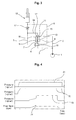
- FIG. 6 which is a graph showing a change of pressure in the case where an option device and another actuator are simultaneously operated
- the pilot pressure 23 for option devices is changed in a state that the pressure 21 of the hydraulic fluid fed from the hydraulic pump 1 forms the pressure 22 of the actuator, normal flow rate 26 of the option device side is simultaneously formed. Accordingly, during the initial operation of the actuator, an excessive flow rate that exceeds the predetermined flow rate is not generated, and thus the flow rate being fed to the actuator can be stably controlled.
- the flow control apparatus for heavy construction equipment has the following advantages.
- the flow rate can be uniformly fed to the actuator without deterioration of the performance of the flow control valve (i.e., the logic poppet). Accordingly, the overload and abrupt operations of the actuator due to the supply of an excessive flow rate which is caused by the peak flow rate generated during the initial operation of the actuator can be prevented, and thus stability, reliability, and workability of the equipment can be improved.
- the back pressure is prevented from being formed in the back chamber of the flow control valve, and thus the hydraulic fluid can be smoothly supplied to the option device to improve the reliability and working efficiency of the equipment.
Landscapes
- Engineering & Computer Science (AREA)
- General Engineering & Computer Science (AREA)
- Mining & Mineral Resources (AREA)
- Civil Engineering (AREA)
- Structural Engineering (AREA)
- Physics & Mathematics (AREA)
- Fluid Mechanics (AREA)
- Mechanical Engineering (AREA)
- Operation Control Of Excavators (AREA)
- Fluid-Pressure Circuits (AREA)
Applications Claiming Priority (1)
| Application Number | Priority Date | Filing Date | Title |
|---|---|---|---|
| KR1020070093654A KR100974273B1 (ko) | 2007-09-14 | 2007-09-14 | 건설중장비용 유량 제어장치 |
Publications (2)
| Publication Number | Publication Date |
|---|---|
| EP2037048A2 true EP2037048A2 (de) | 2009-03-18 |
| EP2037048A3 EP2037048A3 (de) | 2016-12-21 |
Family
ID=39872600
Family Applications (1)
| Application Number | Title | Priority Date | Filing Date |
|---|---|---|---|
| EP08016036.9A Withdrawn EP2037048A3 (de) | 2007-09-14 | 2008-09-11 | Vorrichtung zur Durchfluß-Steuerung für schwere Arbeitsausrüstung. |
Country Status (5)
| Country | Link |
|---|---|
| US (1) | US7987764B2 (de) |
| EP (1) | EP2037048A3 (de) |
| JP (1) | JP5457653B2 (de) |
| KR (1) | KR100974273B1 (de) |
| CN (1) | CN101387309B (de) |
Families Citing this family (14)
| Publication number | Priority date | Publication date | Assignee | Title |
|---|---|---|---|---|
| KR101112133B1 (ko) * | 2009-06-16 | 2012-02-22 | 볼보 컨스트럭션 이큅먼트 에이비 | 플로트 기능을 갖는 건설장비용 유압시스템 |
| JP5848457B2 (ja) | 2011-10-27 | 2016-01-27 | ボルボ コンストラクション イクイップメント アーベー | アクチュエータ衝撃低減システム付きハイブリッド掘削機 |
| EP2985391B1 (de) | 2013-04-03 | 2018-02-28 | Doosan Infracore Co., Ltd. | Vorrichtung und verfahren zur variablen steuerung der spulenverschiebung einer baumaschine |
| CA2879269C (en) | 2014-01-20 | 2021-11-09 | Posi-Plus Technologies Inc. | Hydraulic system for extreme climates |
| JP6205339B2 (ja) | 2014-08-01 | 2017-09-27 | 株式会社神戸製鋼所 | 油圧駆動装置 |
| JP6490709B2 (ja) * | 2014-11-28 | 2019-03-27 | 住友建機株式会社 | 道路機械 |
| WO2017191855A1 (ko) * | 2016-05-03 | 2017-11-09 | 볼보 컨스트럭션 이큅먼트 에이비 | 건설기계용 전기유압밸브 장치 |
| CN108105178B (zh) * | 2016-11-25 | 2020-09-08 | 上海朝冶机电成套设备有限公司 | 具有差动功能的电控泄压机构 |
| CN108105175B (zh) * | 2016-11-25 | 2020-10-27 | 大唐邓州生物质能热电有限责任公司 | 通过溢流阀保压的电控泄压机构 |
| CN108105174A (zh) * | 2016-11-25 | 2018-06-01 | 天津晟金创科技有限公司 | 具有保压功能的电控泄压机构 |
| CN108105207A (zh) * | 2016-11-25 | 2018-06-01 | 天津宝仑信息技术有限公司 | 电控泄压机构 |
| CN108105177B (zh) * | 2016-11-25 | 2020-08-11 | 北京科荣达航空设备科技有限公司 | 具有双重降压功能的电控泄压机构 |
| CN108240360A (zh) * | 2016-12-26 | 2018-07-03 | 家诺天华(天津)科技发展有限公司 | 具有联动功能的电控泄压机构 |
| US11391307B2 (en) * | 2020-01-21 | 2022-07-19 | Caterpillar Paving Products Inc. | Hydraulic tank protection system |
Family Cites Families (13)
| Publication number | Priority date | Publication date | Assignee | Title |
|---|---|---|---|---|
| SE459271B (sv) * | 1987-10-27 | 1989-06-19 | Bahco Hydrauto Ab | Tryckmediumventil |
| JP3685923B2 (ja) * | 1998-04-21 | 2005-08-24 | 日立建機株式会社 | 配管破断制御弁装置 |
| JP2001193709A (ja) | 1999-12-28 | 2001-07-17 | Kayaba Ind Co Ltd | 油圧制御装置 |
| JP3727828B2 (ja) * | 2000-05-19 | 2005-12-21 | 日立建機株式会社 | 配管破断制御弁装置 |
| KR100406275B1 (ko) * | 2000-12-14 | 2003-11-17 | 볼보 컨스트럭션 이키프먼트 홀딩 스웨덴 에이비 | 중장비 옵션장치용 유압회로 |
| KR20030052031A (ko) * | 2001-12-20 | 2003-06-26 | 볼보 컨스트럭션 이키프먼트 홀딩 스웨덴 에이비 | 건설중장비용 유압밸브의 제어장치 |
| US6675904B2 (en) * | 2001-12-20 | 2004-01-13 | Volvo Construction Equipment Holding Sweden Ab | Apparatus for controlling an amount of fluid for heavy construction equipment |
| KR100518768B1 (ko) * | 2003-05-28 | 2005-10-06 | 볼보 컨스트럭션 이키프먼트 홀딩 스웨덴 에이비 | 부하홀딩용 유압밸브의 제어장치 |
| KR100559291B1 (ko) * | 2003-06-25 | 2006-03-15 | 볼보 컨스트럭션 이키프먼트 홀딩 스웨덴 에이비 | 중장비 옵션장치용 유압회로 |
| KR20050081058A (ko) * | 2004-02-12 | 2005-08-18 | 볼보 컨스트럭션 이키프먼트 홀딩 스웨덴 에이비 | 릴리프 밸브 |
| KR100631067B1 (ko) * | 2004-05-04 | 2006-10-02 | 볼보 컨스트럭션 이키프먼트 홀딩 스웨덴 에이비 | 홀딩밸브의 응답성이 개선된 유압제어밸브 |
| KR100631072B1 (ko) * | 2005-06-27 | 2006-10-02 | 볼보 컨스트럭션 이키프먼트 홀딩 스웨덴 에이비 | 중장비 옵션장치용 유압회로 |
| KR100800081B1 (ko) * | 2006-08-29 | 2008-02-01 | 볼보 컨스트럭션 이키프먼트 홀딩 스웨덴 에이비 | 굴삭기용 옵션장치의 유압회로 |
-
2007
- 2007-09-14 KR KR1020070093654A patent/KR100974273B1/ko not_active IP Right Cessation
-
2008
- 2008-09-05 US US12/204,861 patent/US7987764B2/en not_active Expired - Fee Related
- 2008-09-10 JP JP2008231602A patent/JP5457653B2/ja not_active Expired - Fee Related
- 2008-09-11 CN CN2008101496102A patent/CN101387309B/zh not_active Expired - Fee Related
- 2008-09-11 EP EP08016036.9A patent/EP2037048A3/de not_active Withdrawn
Also Published As
| Publication number | Publication date |
|---|---|
| CN101387309B (zh) | 2013-07-10 |
| CN101387309A (zh) | 2009-03-18 |
| US20090071145A1 (en) | 2009-03-19 |
| JP5457653B2 (ja) | 2014-04-02 |
| US7987764B2 (en) | 2011-08-02 |
| KR20090028217A (ko) | 2009-03-18 |
| KR100974273B1 (ko) | 2010-08-06 |
| EP2037048A3 (de) | 2016-12-21 |
| JP2009068708A (ja) | 2009-04-02 |
Similar Documents
| Publication | Publication Date | Title |
|---|---|---|
| US7987764B2 (en) | Flow control apparatus for heavy construction equipment | |
| US7581392B2 (en) | Straight traveling hydraulic circuit | |
| US7175155B2 (en) | Control valve apparatus and pressure circuit | |
| EP2053253B1 (de) | Hydraulisches Wegeventil für Baumaschinen | |
| US8146482B2 (en) | Hydraulic circuit having holding valve of external pilot pressure operation type | |
| JP5948260B2 (ja) | 流体圧制御装置 | |
| EP2264250A2 (de) | Hydrauliksystem für Baumaschinen mit Glättfunktion | |
| CN107250563B (zh) | 用于建筑机械的流量控制阀 | |
| EP1895059B1 (de) | Hydraulische Schaltung einer Optionsvorrichtung für einen Bagger | |
| EP3081819B1 (de) | Vorrichtung zur fluiddrucksteuerung | |
| AU2014262275B2 (en) | Hydraulic valve arrangement with control/regulating function | |
| KR20010086129A (ko) | 배관파단제어밸브장치 | |
| JP4837528B2 (ja) | 油圧機器の油圧回路 | |
| AU2014262272B2 (en) | Hydraulic valve arrangement with control/regulating function | |
| WO2016056564A1 (ja) | 流体圧制御装置 | |
| JP2019056464A (ja) | 流量制御弁 | |
| JP4918001B2 (ja) | 流体圧制御装置 | |
| JP6502813B2 (ja) | 流体圧制御装置 | |
| JP2001187903A (ja) | 配管破断制御弁装置 | |
| KR101486988B1 (ko) | 소형급 건설중장비의 네거티브 유량조절 시스템 | |
| JP2002286002A (ja) | 油圧制御装置 | |
| US10830256B2 (en) | Two-stage valve arrangement for hydraulic control of a piston- cylinder arrangement of a high- or medium-voltage power switch |
Legal Events
| Date | Code | Title | Description |
|---|---|---|---|
| PUAI | Public reference made under article 153(3) epc to a published international application that has entered the european phase |
Free format text: ORIGINAL CODE: 0009012 |
|
| AK | Designated contracting states |
Kind code of ref document: A2 Designated state(s): AT BE BG CH CY CZ DE DK EE ES FI FR GB GR HR HU IE IS IT LI LT LU LV MC MT NL NO PL PT RO SE SI SK TR |
|
| AX | Request for extension of the european patent |
Extension state: AL BA MK RS |
|
| PUAL | Search report despatched |
Free format text: ORIGINAL CODE: 0009013 |
|
| AK | Designated contracting states |
Kind code of ref document: A3 Designated state(s): AT BE BG CH CY CZ DE DK EE ES FI FR GB GR HR HU IE IS IT LI LT LU LV MC MT NL NO PL PT RO SE SI SK TR |
|
| AX | Request for extension of the european patent |
Extension state: AL BA MK RS |
|
| RIC1 | Information provided on ipc code assigned before grant |
Ipc: E02F 9/22 20060101AFI20161115BHEP |
|
| 17P | Request for examination filed |
Effective date: 20170619 |
|
| RBV | Designated contracting states (corrected) |
Designated state(s): AT BE BG CH CY CZ DE DK EE ES FI FR GB GR HR HU IE IS IT LI LT LU LV MC MT NL NO PL PT RO SE SI SK TR |
|
| AKX | Designation fees paid |
Designated state(s): DE FR GB IT |
|
| AXX | Extension fees paid |
Extension state: MK Extension state: RS Extension state: AL Extension state: BA |
|
| STAA | Information on the status of an ep patent application or granted ep patent |
Free format text: STATUS: THE APPLICATION IS DEEMED TO BE WITHDRAWN |
|
| 18D | Application deemed to be withdrawn |
Effective date: 20180404 |