EP2035740B1 - Method and plant for re-gasification of lng - Google Patents
Method and plant for re-gasification of lng Download PDFInfo
- Publication number
- EP2035740B1 EP2035740B1 EP07793892A EP07793892A EP2035740B1 EP 2035740 B1 EP2035740 B1 EP 2035740B1 EP 07793892 A EP07793892 A EP 07793892A EP 07793892 A EP07793892 A EP 07793892A EP 2035740 B1 EP2035740 B1 EP 2035740B1
- Authority
- EP
- European Patent Office
- Prior art keywords
- lng
- plant
- burner
- gasification
- exhaust gas
- Prior art date
- Legal status (The legal status is an assumption and is not a legal conclusion. Google has not performed a legal analysis and makes no representation as to the accuracy of the status listed.)
- Not-in-force
Links
- 238000002309 gasification Methods 0.000 title claims abstract description 24
- 238000000034 method Methods 0.000 title claims abstract description 22
- 239000007789 gas Substances 0.000 claims abstract description 47
- 238000002485 combustion reaction Methods 0.000 claims abstract description 22
- VNWKTOKETHGBQD-UHFFFAOYSA-N methane Chemical compound C VNWKTOKETHGBQD-UHFFFAOYSA-N 0.000 claims abstract description 22
- MYMOFIZGZYHOMD-UHFFFAOYSA-N Dioxygen Chemical compound O=O MYMOFIZGZYHOMD-UHFFFAOYSA-N 0.000 claims abstract description 14
- 239000003345 natural gas Substances 0.000 claims abstract description 9
- 238000000926 separation method Methods 0.000 claims abstract description 9
- 230000008021 deposition Effects 0.000 claims abstract description 8
- 238000001704 evaporation Methods 0.000 claims abstract description 3
- 230000008020 evaporation Effects 0.000 claims abstract description 3
- 238000001816 cooling Methods 0.000 claims description 14
- QVGXLLKOCUKJST-UHFFFAOYSA-N atomic oxygen Chemical compound [O] QVGXLLKOCUKJST-UHFFFAOYSA-N 0.000 claims description 9
- 239000001301 oxygen Substances 0.000 claims description 9
- 229910052760 oxygen Inorganic materials 0.000 claims description 9
- 239000007788 liquid Substances 0.000 claims description 6
- 238000001035 drying Methods 0.000 claims description 3
- CURLTUGMZLYLDI-UHFFFAOYSA-N Carbon dioxide Chemical compound O=C=O CURLTUGMZLYLDI-UHFFFAOYSA-N 0.000 description 58
- 239000003949 liquefied natural gas Substances 0.000 description 47
- IJGRMHOSHXDMSA-UHFFFAOYSA-N Atomic nitrogen Chemical compound N#N IJGRMHOSHXDMSA-UHFFFAOYSA-N 0.000 description 21
- 239000013535 sea water Substances 0.000 description 17
- XLYOFNOQVPJJNP-UHFFFAOYSA-N water Substances O XLYOFNOQVPJJNP-UHFFFAOYSA-N 0.000 description 14
- XKRFYHLGVUSROY-UHFFFAOYSA-N Argon Chemical compound [Ar] XKRFYHLGVUSROY-UHFFFAOYSA-N 0.000 description 10
- 229910052757 nitrogen Inorganic materials 0.000 description 10
- 229910052786 argon Inorganic materials 0.000 description 5
- 238000002347 injection Methods 0.000 description 5
- 239000007924 injection Substances 0.000 description 5
- 238000004519 manufacturing process Methods 0.000 description 5
- 238000003860 storage Methods 0.000 description 5
- UGFAIRIUMAVXCW-UHFFFAOYSA-N Carbon monoxide Chemical compound [O+]#[C-] UGFAIRIUMAVXCW-UHFFFAOYSA-N 0.000 description 4
- 230000000694 effects Effects 0.000 description 4
- 239000003546 flue gas Substances 0.000 description 4
- 238000010438 heat treatment Methods 0.000 description 4
- 238000010248 power generation Methods 0.000 description 4
- 238000005516 engineering process Methods 0.000 description 3
- 239000000047 product Substances 0.000 description 3
- 230000015572 biosynthetic process Effects 0.000 description 2
- 239000002826 coolant Substances 0.000 description 2
- 230000001419 dependent effect Effects 0.000 description 2
- 230000007613 environmental effect Effects 0.000 description 2
- WQYVRQLZKVEZGA-UHFFFAOYSA-N hypochlorite Chemical compound Cl[O-] WQYVRQLZKVEZGA-UHFFFAOYSA-N 0.000 description 2
- 239000011261 inert gas Substances 0.000 description 2
- 238000011084 recovery Methods 0.000 description 2
- 230000008016 vaporization Effects 0.000 description 2
- 239000006200 vaporizer Substances 0.000 description 2
- 241000251468 Actinopterygii Species 0.000 description 1
- 241000947772 Strawberry crinkle virus Species 0.000 description 1
- 238000009825 accumulation Methods 0.000 description 1
- 230000009286 beneficial effect Effects 0.000 description 1
- 238000009835 boiling Methods 0.000 description 1
- 239000006227 byproduct Substances 0.000 description 1
- 235000011089 carbon dioxide Nutrition 0.000 description 1
- 239000000969 carrier Substances 0.000 description 1
- 238000005660 chlorination reaction Methods 0.000 description 1
- 230000006835 compression Effects 0.000 description 1
- 238000007906 compression Methods 0.000 description 1
- 238000009833 condensation Methods 0.000 description 1
- 230000005494 condensation Effects 0.000 description 1
- 238000010586 diagram Methods 0.000 description 1
- 229910001873 dinitrogen Inorganic materials 0.000 description 1
- 238000009826 distribution Methods 0.000 description 1
- 239000003344 environmental pollutant Substances 0.000 description 1
- 239000013505 freshwater Substances 0.000 description 1
- 230000005484 gravity Effects 0.000 description 1
- 239000010797 grey water Substances 0.000 description 1
- 239000008236 heating water Substances 0.000 description 1
- 239000001307 helium Substances 0.000 description 1
- 229910052734 helium Inorganic materials 0.000 description 1
- SWQJXJOGLNCZEY-UHFFFAOYSA-N helium atom Chemical compound [He] SWQJXJOGLNCZEY-UHFFFAOYSA-N 0.000 description 1
- 229930195733 hydrocarbon Natural products 0.000 description 1
- 150000002430 hydrocarbons Chemical class 0.000 description 1
- 239000012535 impurity Substances 0.000 description 1
- 238000005461 lubrication Methods 0.000 description 1
- 238000012423 maintenance Methods 0.000 description 1
- 239000000463 material Substances 0.000 description 1
- 239000003129 oil well Substances 0.000 description 1
- 238000005457 optimization Methods 0.000 description 1
- 231100000719 pollutant Toxicity 0.000 description 1
- 238000005086 pumping Methods 0.000 description 1
- 150000003839 salts Chemical class 0.000 description 1
- 239000000243 solution Substances 0.000 description 1
- 239000004071 soot Substances 0.000 description 1
- 238000009834 vaporization Methods 0.000 description 1
Images
Classifications
-
- F—MECHANICAL ENGINEERING; LIGHTING; HEATING; WEAPONS; BLASTING
- F17—STORING OR DISTRIBUTING GASES OR LIQUIDS
- F17C—VESSELS FOR CONTAINING OR STORING COMPRESSED, LIQUEFIED OR SOLIDIFIED GASES; FIXED-CAPACITY GAS-HOLDERS; FILLING VESSELS WITH, OR DISCHARGING FROM VESSELS, COMPRESSED, LIQUEFIED, OR SOLIDIFIED GASES
- F17C9/00—Methods or apparatus for discharging liquefied or solidified gases from vessels not under pressure
- F17C9/02—Methods or apparatus for discharging liquefied or solidified gases from vessels not under pressure with change of state, e.g. vaporisation
- F17C9/04—Recovery of thermal energy
-
- F—MECHANICAL ENGINEERING; LIGHTING; HEATING; WEAPONS; BLASTING
- F01—MACHINES OR ENGINES IN GENERAL; ENGINE PLANTS IN GENERAL; STEAM ENGINES
- F01K—STEAM ENGINE PLANTS; STEAM ACCUMULATORS; ENGINE PLANTS NOT OTHERWISE PROVIDED FOR; ENGINES USING SPECIAL WORKING FLUIDS OR CYCLES
- F01K13/00—General layout or general methods of operation of complete plants
-
- F—MECHANICAL ENGINEERING; LIGHTING; HEATING; WEAPONS; BLASTING
- F01—MACHINES OR ENGINES IN GENERAL; ENGINE PLANTS IN GENERAL; STEAM ENGINES
- F01K—STEAM ENGINE PLANTS; STEAM ACCUMULATORS; ENGINE PLANTS NOT OTHERWISE PROVIDED FOR; ENGINES USING SPECIAL WORKING FLUIDS OR CYCLES
- F01K15/00—Adaptations of plants for special use
-
- F—MECHANICAL ENGINEERING; LIGHTING; HEATING; WEAPONS; BLASTING
- F02—COMBUSTION ENGINES; HOT-GAS OR COMBUSTION-PRODUCT ENGINE PLANTS
- F02C—GAS-TURBINE PLANTS; AIR INTAKES FOR JET-PROPULSION PLANTS; CONTROLLING FUEL SUPPLY IN AIR-BREATHING JET-PROPULSION PLANTS
- F02C3/00—Gas-turbine plants characterised by the use of combustion products as the working fluid
- F02C3/20—Gas-turbine plants characterised by the use of combustion products as the working fluid using a special fuel, oxidant, or dilution fluid to generate the combustion products
- F02C3/22—Gas-turbine plants characterised by the use of combustion products as the working fluid using a special fuel, oxidant, or dilution fluid to generate the combustion products the fuel or oxidant being gaseous at standard temperature and pressure
-
- F—MECHANICAL ENGINEERING; LIGHTING; HEATING; WEAPONS; BLASTING
- F22—STEAM GENERATION
- F22B—METHODS OF STEAM GENERATION; STEAM BOILERS
- F22B1/00—Methods of steam generation characterised by form of heating method
- F22B1/02—Methods of steam generation characterised by form of heating method by exploitation of the heat content of hot heat carriers
- F22B1/18—Methods of steam generation characterised by form of heating method by exploitation of the heat content of hot heat carriers the heat carrier being a hot gas, e.g. waste gas such as exhaust gas of internal-combustion engines
- F22B1/1838—Methods of steam generation characterised by form of heating method by exploitation of the heat content of hot heat carriers the heat carrier being a hot gas, e.g. waste gas such as exhaust gas of internal-combustion engines the hot gas being under a high pressure, e.g. in chemical installations
-
- F—MECHANICAL ENGINEERING; LIGHTING; HEATING; WEAPONS; BLASTING
- F25—REFRIGERATION OR COOLING; COMBINED HEATING AND REFRIGERATION SYSTEMS; HEAT PUMP SYSTEMS; MANUFACTURE OR STORAGE OF ICE; LIQUEFACTION SOLIDIFICATION OF GASES
- F25J—LIQUEFACTION, SOLIDIFICATION OR SEPARATION OF GASES OR GASEOUS OR LIQUEFIED GASEOUS MIXTURES BY PRESSURE AND COLD TREATMENT OR BY BRINGING THEM INTO THE SUPERCRITICAL STATE
- F25J1/00—Processes or apparatus for liquefying or solidifying gases or gaseous mixtures
- F25J1/0002—Processes or apparatus for liquefying or solidifying gases or gaseous mixtures characterised by the fluid to be liquefied
- F25J1/0027—Oxides of carbon, e.g. CO2
-
- F—MECHANICAL ENGINEERING; LIGHTING; HEATING; WEAPONS; BLASTING
- F25—REFRIGERATION OR COOLING; COMBINED HEATING AND REFRIGERATION SYSTEMS; HEAT PUMP SYSTEMS; MANUFACTURE OR STORAGE OF ICE; LIQUEFACTION SOLIDIFICATION OF GASES
- F25J—LIQUEFACTION, SOLIDIFICATION OR SEPARATION OF GASES OR GASEOUS OR LIQUEFIED GASEOUS MIXTURES BY PRESSURE AND COLD TREATMENT OR BY BRINGING THEM INTO THE SUPERCRITICAL STATE
- F25J1/00—Processes or apparatus for liquefying or solidifying gases or gaseous mixtures
- F25J1/02—Processes or apparatus for liquefying or solidifying gases or gaseous mixtures requiring the use of refrigeration, e.g. of helium or hydrogen ; Details and kind of the refrigeration system used; Integration with other units or processes; Controlling aspects of the process
- F25J1/0221—Processes or apparatus for liquefying or solidifying gases or gaseous mixtures requiring the use of refrigeration, e.g. of helium or hydrogen ; Details and kind of the refrigeration system used; Integration with other units or processes; Controlling aspects of the process using the cold stored in an external cryogenic component in an open refrigeration loop
-
- F—MECHANICAL ENGINEERING; LIGHTING; HEATING; WEAPONS; BLASTING
- F25—REFRIGERATION OR COOLING; COMBINED HEATING AND REFRIGERATION SYSTEMS; HEAT PUMP SYSTEMS; MANUFACTURE OR STORAGE OF ICE; LIQUEFACTION SOLIDIFICATION OF GASES
- F25J—LIQUEFACTION, SOLIDIFICATION OR SEPARATION OF GASES OR GASEOUS OR LIQUEFIED GASEOUS MIXTURES BY PRESSURE AND COLD TREATMENT OR BY BRINGING THEM INTO THE SUPERCRITICAL STATE
- F25J3/00—Processes or apparatus for separating the constituents of gaseous or liquefied gaseous mixtures involving the use of liquefaction or solidification
- F25J3/02—Processes or apparatus for separating the constituents of gaseous or liquefied gaseous mixtures involving the use of liquefaction or solidification by rectification, i.e. by continuous interchange of heat and material between a vapour stream and a liquid stream
- F25J3/04—Processes or apparatus for separating the constituents of gaseous or liquefied gaseous mixtures involving the use of liquefaction or solidification by rectification, i.e. by continuous interchange of heat and material between a vapour stream and a liquid stream for air
- F25J3/04248—Generation of cold for compensating heat leaks or liquid production, e.g. by Joule-Thompson expansion
- F25J3/04254—Generation of cold for compensating heat leaks or liquid production, e.g. by Joule-Thompson expansion using the cold stored in external cryogenic fluids
- F25J3/0426—The cryogenic component does not participate in the fractionation
- F25J3/04266—The cryogenic component does not participate in the fractionation and being liquefied hydrocarbons
-
- F—MECHANICAL ENGINEERING; LIGHTING; HEATING; WEAPONS; BLASTING
- F25—REFRIGERATION OR COOLING; COMBINED HEATING AND REFRIGERATION SYSTEMS; HEAT PUMP SYSTEMS; MANUFACTURE OR STORAGE OF ICE; LIQUEFACTION SOLIDIFICATION OF GASES
- F25J—LIQUEFACTION, SOLIDIFICATION OR SEPARATION OF GASES OR GASEOUS OR LIQUEFIED GASEOUS MIXTURES BY PRESSURE AND COLD TREATMENT OR BY BRINGING THEM INTO THE SUPERCRITICAL STATE
- F25J3/00—Processes or apparatus for separating the constituents of gaseous or liquefied gaseous mixtures involving the use of liquefaction or solidification
- F25J3/02—Processes or apparatus for separating the constituents of gaseous or liquefied gaseous mixtures involving the use of liquefaction or solidification by rectification, i.e. by continuous interchange of heat and material between a vapour stream and a liquid stream
- F25J3/04—Processes or apparatus for separating the constituents of gaseous or liquefied gaseous mixtures involving the use of liquefaction or solidification by rectification, i.e. by continuous interchange of heat and material between a vapour stream and a liquid stream for air
- F25J3/04521—Coupling of the air fractionation unit to an air gas-consuming unit, so-called integrated processes
- F25J3/04527—Integration with an oxygen consuming unit, e.g. glass facility, waste incineration or oxygen based processes in general
- F25J3/04533—Integration with an oxygen consuming unit, e.g. glass facility, waste incineration or oxygen based processes in general for the direct combustion of fuels in a power plant, so-called "oxyfuel combustion"
-
- F—MECHANICAL ENGINEERING; LIGHTING; HEATING; WEAPONS; BLASTING
- F17—STORING OR DISTRIBUTING GASES OR LIQUIDS
- F17C—VESSELS FOR CONTAINING OR STORING COMPRESSED, LIQUEFIED OR SOLIDIFIED GASES; FIXED-CAPACITY GAS-HOLDERS; FILLING VESSELS WITH, OR DISCHARGING FROM VESSELS, COMPRESSED, LIQUEFIED, OR SOLIDIFIED GASES
- F17C2221/00—Handled fluid, in particular type of fluid
- F17C2221/03—Mixtures
- F17C2221/032—Hydrocarbons
- F17C2221/033—Methane, e.g. natural gas, CNG, LNG, GNL, GNC, PLNG
-
- F—MECHANICAL ENGINEERING; LIGHTING; HEATING; WEAPONS; BLASTING
- F17—STORING OR DISTRIBUTING GASES OR LIQUIDS
- F17C—VESSELS FOR CONTAINING OR STORING COMPRESSED, LIQUEFIED OR SOLIDIFIED GASES; FIXED-CAPACITY GAS-HOLDERS; FILLING VESSELS WITH, OR DISCHARGING FROM VESSELS, COMPRESSED, LIQUEFIED, OR SOLIDIFIED GASES
- F17C2223/00—Handled fluid before transfer, i.e. state of fluid when stored in the vessel or before transfer from the vessel
- F17C2223/01—Handled fluid before transfer, i.e. state of fluid when stored in the vessel or before transfer from the vessel characterised by the phase
- F17C2223/0146—Two-phase
- F17C2223/0153—Liquefied gas, e.g. LPG, GPL
- F17C2223/0161—Liquefied gas, e.g. LPG, GPL cryogenic, e.g. LNG, GNL, PLNG
-
- F—MECHANICAL ENGINEERING; LIGHTING; HEATING; WEAPONS; BLASTING
- F17—STORING OR DISTRIBUTING GASES OR LIQUIDS
- F17C—VESSELS FOR CONTAINING OR STORING COMPRESSED, LIQUEFIED OR SOLIDIFIED GASES; FIXED-CAPACITY GAS-HOLDERS; FILLING VESSELS WITH, OR DISCHARGING FROM VESSELS, COMPRESSED, LIQUEFIED, OR SOLIDIFIED GASES
- F17C2223/00—Handled fluid before transfer, i.e. state of fluid when stored in the vessel or before transfer from the vessel
- F17C2223/03—Handled fluid before transfer, i.e. state of fluid when stored in the vessel or before transfer from the vessel characterised by the pressure level
- F17C2223/033—Small pressure, e.g. for liquefied gas
-
- F—MECHANICAL ENGINEERING; LIGHTING; HEATING; WEAPONS; BLASTING
- F17—STORING OR DISTRIBUTING GASES OR LIQUIDS
- F17C—VESSELS FOR CONTAINING OR STORING COMPRESSED, LIQUEFIED OR SOLIDIFIED GASES; FIXED-CAPACITY GAS-HOLDERS; FILLING VESSELS WITH, OR DISCHARGING FROM VESSELS, COMPRESSED, LIQUEFIED, OR SOLIDIFIED GASES
- F17C2225/00—Handled fluid after transfer, i.e. state of fluid after transfer from the vessel
- F17C2225/01—Handled fluid after transfer, i.e. state of fluid after transfer from the vessel characterised by the phase
- F17C2225/0107—Single phase
- F17C2225/0123—Single phase gaseous, e.g. CNG, GNC
-
- F—MECHANICAL ENGINEERING; LIGHTING; HEATING; WEAPONS; BLASTING
- F17—STORING OR DISTRIBUTING GASES OR LIQUIDS
- F17C—VESSELS FOR CONTAINING OR STORING COMPRESSED, LIQUEFIED OR SOLIDIFIED GASES; FIXED-CAPACITY GAS-HOLDERS; FILLING VESSELS WITH, OR DISCHARGING FROM VESSELS, COMPRESSED, LIQUEFIED, OR SOLIDIFIED GASES
- F17C2227/00—Transfer of fluids, i.e. method or means for transferring the fluid; Heat exchange with the fluid
- F17C2227/01—Propulsion of the fluid
- F17C2227/0128—Propulsion of the fluid with pumps or compressors
- F17C2227/0135—Pumps
-
- F—MECHANICAL ENGINEERING; LIGHTING; HEATING; WEAPONS; BLASTING
- F17—STORING OR DISTRIBUTING GASES OR LIQUIDS
- F17C—VESSELS FOR CONTAINING OR STORING COMPRESSED, LIQUEFIED OR SOLIDIFIED GASES; FIXED-CAPACITY GAS-HOLDERS; FILLING VESSELS WITH, OR DISCHARGING FROM VESSELS, COMPRESSED, LIQUEFIED, OR SOLIDIFIED GASES
- F17C2227/00—Transfer of fluids, i.e. method or means for transferring the fluid; Heat exchange with the fluid
- F17C2227/01—Propulsion of the fluid
- F17C2227/0128—Propulsion of the fluid with pumps or compressors
- F17C2227/0157—Compressors
-
- F—MECHANICAL ENGINEERING; LIGHTING; HEATING; WEAPONS; BLASTING
- F17—STORING OR DISTRIBUTING GASES OR LIQUIDS
- F17C—VESSELS FOR CONTAINING OR STORING COMPRESSED, LIQUEFIED OR SOLIDIFIED GASES; FIXED-CAPACITY GAS-HOLDERS; FILLING VESSELS WITH, OR DISCHARGING FROM VESSELS, COMPRESSED, LIQUEFIED, OR SOLIDIFIED GASES
- F17C2227/00—Transfer of fluids, i.e. method or means for transferring the fluid; Heat exchange with the fluid
- F17C2227/03—Heat exchange with the fluid
- F17C2227/0302—Heat exchange with the fluid by heating
- F17C2227/0309—Heat exchange with the fluid by heating using another fluid
- F17C2227/0311—Air heating
-
- F—MECHANICAL ENGINEERING; LIGHTING; HEATING; WEAPONS; BLASTING
- F17—STORING OR DISTRIBUTING GASES OR LIQUIDS
- F17C—VESSELS FOR CONTAINING OR STORING COMPRESSED, LIQUEFIED OR SOLIDIFIED GASES; FIXED-CAPACITY GAS-HOLDERS; FILLING VESSELS WITH, OR DISCHARGING FROM VESSELS, COMPRESSED, LIQUEFIED, OR SOLIDIFIED GASES
- F17C2227/00—Transfer of fluids, i.e. method or means for transferring the fluid; Heat exchange with the fluid
- F17C2227/03—Heat exchange with the fluid
- F17C2227/0302—Heat exchange with the fluid by heating
- F17C2227/0309—Heat exchange with the fluid by heating using another fluid
- F17C2227/0323—Heat exchange with the fluid by heating using another fluid in a closed loop
-
- F—MECHANICAL ENGINEERING; LIGHTING; HEATING; WEAPONS; BLASTING
- F17—STORING OR DISTRIBUTING GASES OR LIQUIDS
- F17C—VESSELS FOR CONTAINING OR STORING COMPRESSED, LIQUEFIED OR SOLIDIFIED GASES; FIXED-CAPACITY GAS-HOLDERS; FILLING VESSELS WITH, OR DISCHARGING FROM VESSELS, COMPRESSED, LIQUEFIED, OR SOLIDIFIED GASES
- F17C2227/00—Transfer of fluids, i.e. method or means for transferring the fluid; Heat exchange with the fluid
- F17C2227/03—Heat exchange with the fluid
- F17C2227/0302—Heat exchange with the fluid by heating
- F17C2227/0332—Heat exchange with the fluid by heating by burning a combustible
-
- F—MECHANICAL ENGINEERING; LIGHTING; HEATING; WEAPONS; BLASTING
- F17—STORING OR DISTRIBUTING GASES OR LIQUIDS
- F17C—VESSELS FOR CONTAINING OR STORING COMPRESSED, LIQUEFIED OR SOLIDIFIED GASES; FIXED-CAPACITY GAS-HOLDERS; FILLING VESSELS WITH, OR DISCHARGING FROM VESSELS, COMPRESSED, LIQUEFIED, OR SOLIDIFIED GASES
- F17C2227/00—Transfer of fluids, i.e. method or means for transferring the fluid; Heat exchange with the fluid
- F17C2227/03—Heat exchange with the fluid
- F17C2227/0337—Heat exchange with the fluid by cooling
- F17C2227/0341—Heat exchange with the fluid by cooling using another fluid
- F17C2227/0353—Heat exchange with the fluid by cooling using another fluid using cryocooler
-
- F—MECHANICAL ENGINEERING; LIGHTING; HEATING; WEAPONS; BLASTING
- F17—STORING OR DISTRIBUTING GASES OR LIQUIDS
- F17C—VESSELS FOR CONTAINING OR STORING COMPRESSED, LIQUEFIED OR SOLIDIFIED GASES; FIXED-CAPACITY GAS-HOLDERS; FILLING VESSELS WITH, OR DISCHARGING FROM VESSELS, COMPRESSED, LIQUEFIED, OR SOLIDIFIED GASES
- F17C2227/00—Transfer of fluids, i.e. method or means for transferring the fluid; Heat exchange with the fluid
- F17C2227/03—Heat exchange with the fluid
- F17C2227/0337—Heat exchange with the fluid by cooling
- F17C2227/0365—Heat exchange with the fluid by cooling with recovery of heat
-
- F—MECHANICAL ENGINEERING; LIGHTING; HEATING; WEAPONS; BLASTING
- F17—STORING OR DISTRIBUTING GASES OR LIQUIDS
- F17C—VESSELS FOR CONTAINING OR STORING COMPRESSED, LIQUEFIED OR SOLIDIFIED GASES; FIXED-CAPACITY GAS-HOLDERS; FILLING VESSELS WITH, OR DISCHARGING FROM VESSELS, COMPRESSED, LIQUEFIED, OR SOLIDIFIED GASES
- F17C2227/00—Transfer of fluids, i.e. method or means for transferring the fluid; Heat exchange with the fluid
- F17C2227/03—Heat exchange with the fluid
- F17C2227/0367—Localisation of heat exchange
- F17C2227/0388—Localisation of heat exchange separate
- F17C2227/039—Localisation of heat exchange separate on the pipes
-
- F—MECHANICAL ENGINEERING; LIGHTING; HEATING; WEAPONS; BLASTING
- F17—STORING OR DISTRIBUTING GASES OR LIQUIDS
- F17C—VESSELS FOR CONTAINING OR STORING COMPRESSED, LIQUEFIED OR SOLIDIFIED GASES; FIXED-CAPACITY GAS-HOLDERS; FILLING VESSELS WITH, OR DISCHARGING FROM VESSELS, COMPRESSED, LIQUEFIED, OR SOLIDIFIED GASES
- F17C2260/00—Purposes of gas storage and gas handling
- F17C2260/04—Reducing risks and environmental impact
- F17C2260/044—Avoiding pollution or contamination
-
- F—MECHANICAL ENGINEERING; LIGHTING; HEATING; WEAPONS; BLASTING
- F17—STORING OR DISTRIBUTING GASES OR LIQUIDS
- F17C—VESSELS FOR CONTAINING OR STORING COMPRESSED, LIQUEFIED OR SOLIDIFIED GASES; FIXED-CAPACITY GAS-HOLDERS; FILLING VESSELS WITH, OR DISCHARGING FROM VESSELS, COMPRESSED, LIQUEFIED, OR SOLIDIFIED GASES
- F17C2265/00—Effects achieved by gas storage or gas handling
- F17C2265/05—Regasification
-
- F—MECHANICAL ENGINEERING; LIGHTING; HEATING; WEAPONS; BLASTING
- F17—STORING OR DISTRIBUTING GASES OR LIQUIDS
- F17C—VESSELS FOR CONTAINING OR STORING COMPRESSED, LIQUEFIED OR SOLIDIFIED GASES; FIXED-CAPACITY GAS-HOLDERS; FILLING VESSELS WITH, OR DISCHARGING FROM VESSELS, COMPRESSED, LIQUEFIED, OR SOLIDIFIED GASES
- F17C2265/00—Effects achieved by gas storage or gas handling
- F17C2265/07—Generating electrical power as side effect
-
- F—MECHANICAL ENGINEERING; LIGHTING; HEATING; WEAPONS; BLASTING
- F17—STORING OR DISTRIBUTING GASES OR LIQUIDS
- F17C—VESSELS FOR CONTAINING OR STORING COMPRESSED, LIQUEFIED OR SOLIDIFIED GASES; FIXED-CAPACITY GAS-HOLDERS; FILLING VESSELS WITH, OR DISCHARGING FROM VESSELS, COMPRESSED, LIQUEFIED, OR SOLIDIFIED GASES
- F17C2270/00—Applications
- F17C2270/01—Applications for fluid transport or storage
- F17C2270/0102—Applications for fluid transport or storage on or in the water
- F17C2270/0105—Ships
-
- F—MECHANICAL ENGINEERING; LIGHTING; HEATING; WEAPONS; BLASTING
- F25—REFRIGERATION OR COOLING; COMBINED HEATING AND REFRIGERATION SYSTEMS; HEAT PUMP SYSTEMS; MANUFACTURE OR STORAGE OF ICE; LIQUEFACTION SOLIDIFICATION OF GASES
- F25J—LIQUEFACTION, SOLIDIFICATION OR SEPARATION OF GASES OR GASEOUS OR LIQUEFIED GASEOUS MIXTURES BY PRESSURE AND COLD TREATMENT OR BY BRINGING THEM INTO THE SUPERCRITICAL STATE
- F25J2210/00—Processes characterised by the type or other details of the feed stream
- F25J2210/62—Liquefied natural gas [LNG]; Natural gas liquids [NGL]; Liquefied petroleum gas [LPG]
-
- F—MECHANICAL ENGINEERING; LIGHTING; HEATING; WEAPONS; BLASTING
- F25—REFRIGERATION OR COOLING; COMBINED HEATING AND REFRIGERATION SYSTEMS; HEAT PUMP SYSTEMS; MANUFACTURE OR STORAGE OF ICE; LIQUEFACTION SOLIDIFICATION OF GASES
- F25J—LIQUEFACTION, SOLIDIFICATION OR SEPARATION OF GASES OR GASEOUS OR LIQUEFIED GASEOUS MIXTURES BY PRESSURE AND COLD TREATMENT OR BY BRINGING THEM INTO THE SUPERCRITICAL STATE
- F25J2220/00—Processes or apparatus involving steps for the removal of impurities
- F25J2220/80—Separating impurities from carbon dioxide, e.g. H2O or water-soluble contaminants
- F25J2220/82—Separating low boiling, i.e. more volatile components, e.g. He, H2, CO, Air gases, CH4
-
- F—MECHANICAL ENGINEERING; LIGHTING; HEATING; WEAPONS; BLASTING
- F25—REFRIGERATION OR COOLING; COMBINED HEATING AND REFRIGERATION SYSTEMS; HEAT PUMP SYSTEMS; MANUFACTURE OR STORAGE OF ICE; LIQUEFACTION SOLIDIFICATION OF GASES
- F25J—LIQUEFACTION, SOLIDIFICATION OR SEPARATION OF GASES OR GASEOUS OR LIQUEFIED GASEOUS MIXTURES BY PRESSURE AND COLD TREATMENT OR BY BRINGING THEM INTO THE SUPERCRITICAL STATE
- F25J2260/00—Coupling of processes or apparatus to other units; Integrated schemes
- F25J2260/80—Integration in an installation using carbon dioxide, e.g. for EOR, sequestration, refrigeration etc.
Definitions
- the present invention relates to an environmental friendly re-gasification process for LNG. More specifically the invention relates to a method and plant for re-gasification of LNG, that allows for re-gasification of LNG with no, or substantially reduced, environmental impact, such as cooling of seawater and emission of CO 2 to the atmosphere.
- LNG Liquefied Natural Gas
- the gas is liquefied prior to transport from the gas production location and is transported as a cooled liquid in LNG carriers.
- the tankers delivers the LNG to a LNG re-gasification terminal comprising LNG tanker unloading facilities, LNG storage tanks, re-gasification units and gas export pipeline(s).
- the LNG has to be re-gasified before it can be transmitted through a pipeline distribution network.
- the re-gasification takes place in the re-gasification unit.
- Traditionally two different vaporizing technologies are used in the re-gasification process. These are Submerged Combustion Vaporisers (SCV) using a burner as the heat source, and Open Rack Vaporizers (OVR) using seawater as the heat source. Additionally, heat exchangers for a closed loop heating medium system, using seawater and/or heat recovery from power systems or air as heat source, exist.
- the gas export pipeline pressure in all the mentioned units are achieved by high pressure pumps in the liquid LNG phase.
- An SCV consists of a gas burner where part of the burner and the flue gas ducting are submerged in a water bed.
- the LNG vaporizer is also submerged in the heated water.
- a local fan attached to the SCV supplies necessary combustion air. This gives a very high heat exchange rate and a compact heat exchanger
- An ORV is a battery of vertical radiators above a sump, where seawater is continuously flowing down the external faces of the radiators by gravity, as high pressure LNG is boiling inside. The amount of necessary seawater is dependent on the available (or allowable) temperature drop of the heating water discharge. For an ORV facility the two by far largest power consumption items are the LNG and seawater pumps.
- seawater inlets are equipped with fine meshed strainers to limit zooplankton and fish larvae to enter the seawater and vaporizer system.
- the seawater is dyed with hypochlorite to prevent marine growth in the piping system.
- the seawater outlet is arranged with a huge diffuser to disperse the cooled water into the surrounding water mass, to prevent larger local temperature differences.
- environmentalists have expressed objections to both intake/chlorination and outlet/temperature changes, since both have undesirable effects on the marine life.
- the seawater intake system is large, and thus costly since the water inlet velocity in the strainers is kept very low to limit the unfavorable effects on marine life.
- the LNG Regasification terminal is normally powered by a modem, industrialized air plane derivative jet engine. These engines have low temperature burners where nitrogen is not oxidized and are run with a surplus of air to limit CO formation. The result is a flue gas with only traces of NO X , CO and soot. The major part of the flue gas is then nitrogen and CO 2 .
- the invention relates to a method for re-gasification of LNG in which method natural gas is combusted in a burner to provide heat for evaporation of the LNG and where the heat is transferred from the burner to the LNG in a closed heat exchange system, wherein substantially pure oxygen is used in the combustion of natural gas, and that CO 2 is separated from the exhaust gas for export or deposition.
- substantially pure oxygen for the combustion results in an exhaust gas comprising H 2 O and CO 2 , which makes it possible to separate the CO 2 by simple means, such as cooling the exhaust gas and condensation of the water vapor.
- This CO 2 may be compressed for deposition or further liquefied for bulk export.
- cooled exhaust from the combustion is re-circulated into the combustion.
- Recirculation of cooled exhaust gas is used primarily to control the temperature in the combustion chamber but will also ensure a more complete combustion of the hydrocarbons in the combustion chamber.
- the exhaust from the combustion mainly comprising CO 2 and H 2 O is dried, compressed and liquefied to be separated to give liquid CO 2 for export or deposition. Drying of the exhaust gas removes water and leaves substantially pure CO 2 . Liquefying of the CO 2 is especially preferable when the CO 2 is to be transported over long distances for example for injection into a field remote from the regasification plant.
- the cooling and liquefying of the CO 2 for export is used to provide energy for gasification and heating of the LNG.
- the present invention provides for a plant for re-gasification of LNG, the plant comprising a gas fired burner for generation of heat for the regasification, a closed heat exchange system for transfer of heat from the burner to LNG to be vaporized, wherein the plant additionally comprises a air separation unit for generation of substantially pure oxygen to be fed to the burner.
- the plant additionally comprises means to cool, dry and compress the CO 2 generated in the burner. Compressing and drying the CO 2 makes it possible to use it for injection into a gas or oil well for deposition in a depleted well, or pressure support to enhance he production in a producing well.
- the plant comprises recirculation lines for recirculation of cooled exhaust gas from the burner into the burner to reduce the combustion temperature.
- Recirculation of exhaust gas improves the control over the combustion, both with regard to combustion temperature and complete combustion.
- the plant also comprises a CO 2 liquefaction unit for liquefaction of CO 2 for export from the plant.
- a CO 2 liquefaction unit is especially preferable if the re-gasification plant placed far from possible injection or deposition sites.
- the plant may additionally comprise power generating means for generation of electrical power.
- a re-gasification plant has a need for electrical power and the power generating means may be dimensioned for the need of the plant. Additionally, electrical power may be exported from the plant.
- the present invention provides for the use of LNG for cooling air in an air separation unit to produce substantially pure oxygen.
- the use of the cold LNG for cooling of the air for the air separation unit avoids or reduces the need for additional cooling of the incoming air, and adds heat to the re-gasification, to improve the energy efficiency of the plant.
- other air gases such as argon, nitrogen, helium are separated in the air separation unit for other uses or sales.
- the separation of other air gases may improve the total energy efficiency and profitability of the plant.
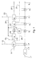
- Figure 1 is a flow schematic diagram illustrating the present invention.
- FIG. 1 illustrates the principle of the present regasification process and plant.
- LNG is delivered from tankers to a terminal and enters the plant through a LNG supply line 1 into a LNG storage 2.
- the LNG storage 2 comprises the necessary piping, tanks and in tank pumps for internal transport, storage and pumping the LNG from the storage 2 into a LNG line 3 by high pressure LNG pumps.
- the high pressure LNG in line 3 is heated in several heat exchangers, here illustrated by in an air cooler 4, a steam condenser 5, a CO 2 cooler 6, a CO 2 condenser 7 and a utility cooler 8, before the re-gasified LNG leaves the plant in a gas export line 9.
- Air entering an air intake 11 into an air separation unit (ASU) 10 is cooled against the LNG in the air cooler 4.
- ASU 10 air is cryogenically separated into substantially pure oxygen, which leaves the ASU through an oxygen line 13, and nitrogen and other air gases, which are released into the atmosphere through a nitrogen line 12 unless other industrial uses can be found for the nitrogen locally.
- substantially pure oxygen is in the present application used for an oxygen enriched gas having an oxygen content of more than 90 %, preferably more than 95% and most preferably more than 98%.
- the oxygen in the oxygen line 13 is introduced into a burner 14, wherein the oxygen is used for generation of heat through combustion of natural gas which enters the burner 14 through a natural gas line 15.
- the hot exhaust gas from the burner 14 is cooled in a heat exchanger 17 against a heat exchange medium in a closed steam and power system 25.
- Said heat exchange medium in the closed system 25 is again used to transfer heat from the hot exhaust gas to the LNG in the steam condenser 5 mentioned above as well as to supply sufficient power in the steam turbine and generator 25 to feed the terminal, as indicated by the line 26.
- the partly cooled exhaust gas mainly comprising water vapor and CO 2
- the gas in the dryer and compressor train mainly comprising CO 2
- the gas in the dryer and compressor train is cooled against the LNG in the CO 2 cooler 6.
- H 2 O that is condensed in the dryer and compressor train is removed in a H 2 O line 21.
- the dried and compressed CO 2 from the dryer and compressor train 18, is thereafter liquefied in a CO 2 liquefaction unit 19.
- the gas in the liquefaction unit 19 is also cooled by heat exchanging in the CO 2 condenser 7, against the LNG in the LNG line.
- Liquefied CO 2 leaves the CO 2 liquefaction unit 19 in a CO 2 line 20, and is sent for export, e.g. for injection into an oil field for enhanced oil production or to be deposited into a depleted oil or gas field or used for industrial purposes.
- a limited amount of flue gas comprising CO 2 , N 2 , Ar and O 2 is not condensed in the liquefaction unit, is split into two streams, one being released into the atmosphere through a stack 23 to avoid enrichment of N 2 and Ar in the process, and the other stream is re-circulated in a CO 2 recirculation line 24 into the burner 14.
- a major part of the cooled exhaust leaving the heat exchanger 17 is re-circulated in a recirculation line 22 back to the burner 14.
- the reasons to re-circulate exhaust gas are several. Firstly, the re-circulated exhaust gas acts as a substantially inert gas in the burner. Combustion of natural gas and substantially pure oxygen would result in far too high combustion temperatures for existing burners and heat exchangers. The recirculation of cooled exhaust makes it possible to control the combustion temperature. Secondly, by re-circulating the exhaust, any remaining combustible materials in the exhaust will be combusted resulting in a more total combustion in the burner. Thirdly, the inert gas adds heat capacity to the exhaust gas and thus enhances the heat transfer in the heat exchangers.
- Heat from the closed steam and power system that is not used for heating the LNG will be used for terminal power production as indicated by line 26 in a steam turbine to make the terminal self sufficient of electrical power.
- Power generation in a gas turbine would be favored as it would yield a higher efficiency for power generation but gas turbine technology is not yet mature for power generation at the high temperatures achieved by fueling by methane and pure oxygen.
- the utility cooler 8 indicates one or more heat exchangers that is/are used for cooling of different process equipment that needs cooling, and may comprise coolers for lubrication oil, hvac-cooling, etc, to avoid using sea water for cooling purposes.
- each of the heat exchangers / coolers 4, 5, 6, 7, 8 illustrated in figure 1 may comprise several heat exchangers.
- the actual configuration of heat exchangers will be subject to optimization both with regard to the number and size of the heat exchangers. Additionally, the relative position of the different heat exchangers 4, 5, 6, 7, 8 may be changed due to optimalization of a plant.
- the burner may be any kind of burner such as a combustion chamber, a boiler or a modem industrialized gas turbine.
- the non discharge regasification system as explained above has been estimated for an LNG facility with 1717t/h (2BSCF/D) sales gas (9).
- the burner (14) will require additional 23.4 t/h of natural gas (15) to be burned with 93.1 t/h pure oxygen (13).
- Almost 700t/h CO 2 is recirculated to the burner (22 and 24).
- a vent line from the CO 2 liquefaction unit discharge 2.5t/h, mostly CO 2 with some N 2 , Ar and O 2 , to the atmosphere (23).
- the steam power system (25) produce the 55MW electrical power (26) required by the Regasification plant.
- the plant further produce:
- Non-Discharge Regas Process has no need for seawater for cooling or heating purposes.
- a Regasification plant utilizing ORV vaporizers may require about 50000 t/h of treated seawater for the same capacity.
- CO 2 is dried before and during compression in two stages to a pressure of 15 bars in the dryer and compressor train unit 18.
- the CO 2 is then dried to avoid formation of ice in the liquefaction system.
- the next step, in the CO 2 liquefaction unit 19, is to cool the CO 2 to -30.8 °C, where it is liquefied and may be pumped, stored and offloaded more easily.
- the cooling is done in a column with the LNG cooled condenser 7.
- the CO 2 rich exhaust is entering close to the bottom of the column, liquid CO 2 is extracted from the bottom and oxygen/nitrogen/argon comes out at the top.
- the column enables a low CO 2 concentration in the top product (7.2 mol%). 50% of the top product is emitted to atmosphere (2500 kg/hr) in order to avoid enrichment of nitrogen/argon (which gets into the process as an impurity in the oxygen).
- a fraction of the CO 2 stream could also be processed to give dry ice as a product, which may be sold as a cooling medium.
- the proposed 'emission free' terminal is not quite emission free. Of process technical reasons a small amount of N 2 , CO 2 and Ar is vented to prevent accumulation of N 2 and Ar in the recycle loop. A fraction of this is CO 2 carried over from the liquefaction column. The only effluent from the terminal to the sea is cleaned grey water and drains from the facility.
- the captured CO 2 is liquefied and can be exported in bulk or by pipe line.
- the terminal is dependent of having a customer for the CO 2 which could be a near by oilfield where the CO 2 can be injected, otherwise the cost of getting rid of the CO 2 will be economically unfeasible.
- the CO 2 can preferably be injected for enhanced oil recovery, or just stored in a depleted field or salt dome. This will limit possible sites for an 'emission free' terminal.
- an LNG regasification terminal may be located close to and utilise an existing gas pipeline to minimize pipeline costs.
- the gas pipeline often originates from production platforms where CO 2 may be beneficial for injection. For limited periods under special conditions, it may be that CO 2 cannot be exported. Then the CO 2 will be discharged to the atmosphere with less unfavourable impacts on the air quality than with traditional technologies.
Landscapes
- Engineering & Computer Science (AREA)
- Mechanical Engineering (AREA)
- General Engineering & Computer Science (AREA)
- Chemical & Material Sciences (AREA)
- Physics & Mathematics (AREA)
- Thermal Sciences (AREA)
- Combustion & Propulsion (AREA)
- Life Sciences & Earth Sciences (AREA)
- Chemical Kinetics & Catalysis (AREA)
- Sustainable Development (AREA)
- Sustainable Energy (AREA)
- Separation By Low-Temperature Treatments (AREA)
- Carbon And Carbon Compounds (AREA)
- Filling Or Discharging Of Gas Storage Vessels (AREA)
- Organic Low-Molecular-Weight Compounds And Preparation Thereof (AREA)
- Air Supply (AREA)
Priority Applications (1)
| Application Number | Priority Date | Filing Date | Title |
|---|---|---|---|
| PL07793892T PL2035740T3 (pl) | 2006-06-20 | 2007-06-20 | Sposób i instalacja do regazyfikacji LNG |
Applications Claiming Priority (2)
| Application Number | Priority Date | Filing Date | Title |
|---|---|---|---|
| NO20062896A NO328260B1 (no) | 2006-06-20 | 2006-06-20 | Fremgangsmate og anlegg for re-gassifisering LNG |
| PCT/NO2007/000218 WO2007148984A2 (en) | 2006-06-20 | 2007-06-20 | Method and plant for re-gasification of lng |
Publications (2)
| Publication Number | Publication Date |
|---|---|
| EP2035740A2 EP2035740A2 (en) | 2009-03-18 |
| EP2035740B1 true EP2035740B1 (en) | 2009-10-14 |
Family
ID=38694804
Family Applications (1)
| Application Number | Title | Priority Date | Filing Date |
|---|---|---|---|
| EP07793892A Not-in-force EP2035740B1 (en) | 2006-06-20 | 2007-06-20 | Method and plant for re-gasification of lng |
Country Status (14)
| Country | Link |
|---|---|
| US (1) | US20090277189A1 (ko) |
| EP (1) | EP2035740B1 (ko) |
| JP (1) | JP2009541522A (ko) |
| KR (1) | KR20090033363A (ko) |
| CN (1) | CN101466976A (ko) |
| AT (1) | ATE445805T1 (ko) |
| CA (1) | CA2656497A1 (ko) |
| DE (1) | DE602007002822D1 (ko) |
| ES (1) | ES2334853T3 (ko) |
| MX (1) | MX2008015940A (ko) |
| NO (1) | NO328260B1 (ko) |
| PL (1) | PL2035740T3 (ko) |
| PT (1) | PT2035740E (ko) |
| WO (1) | WO2007148984A2 (ko) |
Families Citing this family (21)
| Publication number | Priority date | Publication date | Assignee | Title |
|---|---|---|---|---|
| FR2916258B1 (fr) * | 2007-05-18 | 2009-08-28 | Hasan Sigergok | Procede et installation pour l'incineration de dechets avec prechauffage de ceux-ci par les gaz de combustion, la combustion etant realise sans azote avec apport d'oxygene |
| US8950196B2 (en) * | 2008-07-17 | 2015-02-10 | Fluor Technologies Corporation | Configurations and methods for waste heat recovery and ambient air vaporizers in LNG regasification |
| NO331474B1 (no) * | 2009-11-13 | 2012-01-09 | Hamworthy Gas Systems As | Installasjon for gjengassing av LNG |
| US20110289941A1 (en) * | 2010-05-28 | 2011-12-01 | General Electric Company | Brayton cycle regasification of liquiefied natural gas |
| JP5618358B2 (ja) * | 2010-06-18 | 2014-11-05 | 独立行政法人海上技術安全研究所 | 二酸化炭素回収機能付き輸送手段および二酸化炭素の回収処理方法 |
| KR101195149B1 (ko) | 2010-07-06 | 2012-10-29 | 삼성중공업 주식회사 | 액화천연가스의 재기화 장치 및 방법 |
| JP2014512471A (ja) * | 2011-02-01 | 2014-05-22 | アルストム テクノロジー リミテッド | Co2回収プラントを伴う複合サイクル発電プラント |
| CN104160130B (zh) * | 2011-11-02 | 2017-08-25 | 八河流资产有限责任公司 | 发电系统和相应方法 |
| KR101349493B1 (ko) * | 2011-12-28 | 2014-01-09 | 한국가스공사 | 순산소 연소식 기화장치 |
| KR101349518B1 (ko) * | 2011-12-28 | 2014-01-09 | 한국가스공사 | 이산화탄소 포집 및 저장수단이 구비된 연소식 기화장치 |
| CN102705704A (zh) * | 2012-05-30 | 2012-10-03 | 上海工程技术大学 | 一种烟气冲击旋水式lng加热气化炉的烟气循环系统 |
| US20140245779A1 (en) * | 2013-03-04 | 2014-09-04 | Lalit K. Bohra | Regasification Plant |
| CN103628982B (zh) * | 2013-11-27 | 2015-09-09 | 暨南大学 | 利用液化天然气冷能捕集二氧化碳的联合动力循环方法及其系统 |
| CN105233521A (zh) * | 2015-10-26 | 2016-01-13 | 成都华气厚普机电设备股份有限公司 | Lng燃烧尾气co2捕捉系统 |
| CN105605602B (zh) * | 2016-01-28 | 2017-10-31 | 华中科技大学 | 将lng冷能用于空分制氧和碳捕获的天然气富氧燃烧系统 |
| JP6946012B2 (ja) * | 2017-02-09 | 2021-10-06 | 三菱重工業株式会社 | Co2液化システム及びco2液化方法 |
| JP2020008132A (ja) * | 2018-07-11 | 2020-01-16 | 株式会社神戸製鋼所 | 液体空気エネルギー貯蔵装置、発電装置及び混焼火力発電システム |
| KR102352166B1 (ko) * | 2020-04-29 | 2022-01-19 | 한국조선해양 주식회사 | 액화가스 재기화 시스템 및 이를 포함하는 선박 |
| IT202000032210A1 (it) * | 2020-12-23 | 2022-06-23 | Saipem Spa | Sistema integrato per l’accumulo di potenza o per la generazione di energia elettrica e gas naturale |
| EP4242567A1 (de) * | 2022-03-08 | 2023-09-13 | Linde GmbH | Verfahren und anlage zum zumindest teilweisen verflüssigen eines gasgemisches |
| DE102022110580A1 (de) * | 2022-04-29 | 2023-11-02 | Dürr Systems Ag | Anlage mit wärmetauscher und anlagen-betriebsverfahren |
Family Cites Families (15)
| Publication number | Priority date | Publication date | Assignee | Title |
|---|---|---|---|---|
| GB933584A (en) * | 1962-05-02 | 1963-08-08 | Conch Int Methane Ltd | A method of gasifying a liquefied gas while producing mechanical energy |
| DE2062003A1 (en) * | 1970-12-16 | 1972-06-22 | Linde Ag, 6200 Wiesbaden | Nitrogen extraction - from flue gas for use as coolant in storage or transport of natural gas |
| US3726101A (en) * | 1971-05-20 | 1973-04-10 | Black Sivalls & Bryson Inc | Method of continuously vaporizing and superheating liquefied cryogenic fluid |
| US3726085A (en) * | 1971-06-07 | 1973-04-10 | Back Sivalls & Bryson Inc | Preventing thermal pollution of ambient water used as a process cooling medium |
| DE2307004A1 (de) * | 1973-02-13 | 1974-08-15 | Linde Ag | Verfahren und vorrichtung zur gewinnung von fluessigem stickstoff |
| DE2651851A1 (de) * | 1976-01-22 | 1977-07-28 | Sulzer Ag | Verfahren und anlage zur gewinnung von stickstoffhaltigem erdgas |
| US4995234A (en) * | 1989-10-02 | 1991-02-26 | Chicago Bridge & Iron Technical Services Company | Power generation from LNG |
| US5295350A (en) * | 1992-06-26 | 1994-03-22 | Texaco Inc. | Combined power cycle with liquefied natural gas (LNG) and synthesis or fuel gas |
| BR9405757A (pt) * | 1993-12-10 | 1995-11-28 | Cabot Corp | Processo para aumentar capacidade e eficiencia de instalação de ciclos combinados e sistema de instalação de ciclo combinado de gás natural liquefeito |
| US6170264B1 (en) * | 1997-09-22 | 2001-01-09 | Clean Energy Systems, Inc. | Hydrocarbon combustion power generation system with CO2 sequestration |
| US6148602A (en) * | 1998-08-12 | 2000-11-21 | Norther Research & Engineering Corporation | Solid-fueled power generation system with carbon dioxide sequestration and method therefor |
| US6345493B1 (en) * | 1999-06-04 | 2002-02-12 | Air Products And Chemicals, Inc. | Air separation process and system with gas turbine drivers |
| AU2002360505A1 (en) * | 2001-12-03 | 2003-06-17 | Clean Energy Systems, Inc. | Coal and syngas fueled power generation systems featuring zero atmospheric emissions |
| US6598408B1 (en) * | 2002-03-29 | 2003-07-29 | El Paso Corporation | Method and apparatus for transporting LNG |
| US20050241311A1 (en) * | 2004-04-16 | 2005-11-03 | Pronske Keith L | Zero emissions closed rankine cycle power system |
-
2006
- 2006-06-20 NO NO20062896A patent/NO328260B1/no not_active IP Right Cessation
-
2007
- 2007-06-20 AT AT07793892T patent/ATE445805T1/de not_active IP Right Cessation
- 2007-06-20 DE DE602007002822T patent/DE602007002822D1/de active Active
- 2007-06-20 CN CNA2007800222522A patent/CN101466976A/zh active Pending
- 2007-06-20 EP EP07793892A patent/EP2035740B1/en not_active Not-in-force
- 2007-06-20 JP JP2009516422A patent/JP2009541522A/ja not_active Withdrawn
- 2007-06-20 KR KR1020097001132A patent/KR20090033363A/ko not_active Application Discontinuation
- 2007-06-20 US US12/305,578 patent/US20090277189A1/en not_active Abandoned
- 2007-06-20 CA CA002656497A patent/CA2656497A1/en not_active Abandoned
- 2007-06-20 PL PL07793892T patent/PL2035740T3/pl unknown
- 2007-06-20 ES ES07793892T patent/ES2334853T3/es active Active
- 2007-06-20 WO PCT/NO2007/000218 patent/WO2007148984A2/en active Application Filing
- 2007-06-20 PT PT07793892T patent/PT2035740E/pt unknown
- 2007-06-20 MX MX2008015940A patent/MX2008015940A/es active IP Right Grant
Also Published As
| Publication number | Publication date |
|---|---|
| PT2035740E (pt) | 2009-12-17 |
| JP2009541522A (ja) | 2009-11-26 |
| PL2035740T3 (pl) | 2010-03-31 |
| DE602007002822D1 (de) | 2009-11-26 |
| MX2008015940A (es) | 2009-02-23 |
| NO20062896L (no) | 2007-12-21 |
| NO328260B1 (no) | 2010-01-18 |
| ES2334853T3 (es) | 2010-03-16 |
| ATE445805T1 (de) | 2009-10-15 |
| CA2656497A1 (en) | 2007-12-27 |
| WO2007148984A2 (en) | 2007-12-27 |
| KR20090033363A (ko) | 2009-04-02 |
| EP2035740A2 (en) | 2009-03-18 |
| CN101466976A (zh) | 2009-06-24 |
| WO2007148984A3 (en) | 2008-02-07 |
| US20090277189A1 (en) | 2009-11-12 |
Similar Documents
| Publication | Publication Date | Title |
|---|---|---|
| EP2035740B1 (en) | Method and plant for re-gasification of lng | |
| JP6449304B2 (ja) | 極低温タンクから蒸気を回収するための装置 | |
| US10584830B2 (en) | Apparatus, system and method for the capture, utilization and sendout of latent heat in boil off gas onboard a cryogenic storage vessel | |
| US10030815B2 (en) | Method and apparatus for reliquefying natural gas | |
| US20130291567A1 (en) | Regasification Plant | |
| US20030005698A1 (en) | LNG regassification process and system | |
| US20080053110A1 (en) | Apparatus And Methods For Converting A Cryogenic Fluid Into Gas | |
| EA033615B1 (ru) | Комбинированный цикл регазификации топлива и производства энергии | |
| JP5354543B2 (ja) | 外気式気化器 | |
| US20140245779A1 (en) | Regasification Plant | |
| US20130152607A1 (en) | Process and plant for the vaporization of liquefied natural gas and storage thereof | |
| KR102514327B1 (ko) | 극저온 액체의 증발로부터 야기되는 가스를 처리하기 위한 시스템 및 방법 | |
| US6079222A (en) | Method for preparing deep-frozen liquid gas | |
| KR101951174B1 (ko) | 재기화 플랜트 | |
| US20140130521A1 (en) | Configurations and Methods for Ambient Air Vaporizers and Cold Utilization | |
| US20180313497A1 (en) | Method of an apparatus for treating boil-off gas for the purpose of supplying at least an engine | |
| RU2352876C1 (ru) | Система ожижения двуокиси углерода из смеси отводимых газов, отработавших в воздухонезависимой энергоустановке на углеводородном горючем | |
| MXPA04008252A (es) | Aparato y metodo para enfriar el aire de entrada de una turbina de combustion utilizando combustible a base de hidrocarburo. |
Legal Events
| Date | Code | Title | Description |
|---|---|---|---|
| PUAI | Public reference made under article 153(3) epc to a published international application that has entered the european phase |
Free format text: ORIGINAL CODE: 0009012 |
|
| 17P | Request for examination filed |
Effective date: 20090108 |
|
| AK | Designated contracting states |
Kind code of ref document: A2 Designated state(s): AT BE BG CH CY CZ DE DK EE ES FI FR GB GR HU IE IS IT LI LT LU LV MC MT NL PL PT RO SE SI SK TR |
|
| AX | Request for extension of the european patent |
Extension state: AL BA HR MK RS |
|
| GRAP | Despatch of communication of intention to grant a patent |
Free format text: ORIGINAL CODE: EPIDOSNIGR1 |
|
| DAX | Request for extension of the european patent (deleted) | ||
| GRAS | Grant fee paid |
Free format text: ORIGINAL CODE: EPIDOSNIGR3 |
|
| GRAA | (expected) grant |
Free format text: ORIGINAL CODE: 0009210 |
|
| AK | Designated contracting states |
Kind code of ref document: B1 Designated state(s): AT BE BG CH CY CZ DE DK EE ES FI FR GB GR HU IE IS IT LI LT LU LV MC MT NL PL PT RO SE SI SK TR |
|
| REG | Reference to a national code |
Ref country code: GB Ref legal event code: FG4D |
|
| REG | Reference to a national code |
Ref country code: CH Ref legal event code: EP |
|
| REG | Reference to a national code |
Ref country code: IE Ref legal event code: FG4D |
|
| REF | Corresponds to: |
Ref document number: 602007002822 Country of ref document: DE Date of ref document: 20091126 Kind code of ref document: P |
|
| REG | Reference to a national code |
Ref country code: PT Ref legal event code: SC4A Free format text: AVAILABILITY OF NATIONAL TRANSLATION Effective date: 20091210 |
|
| REG | Reference to a national code |
Ref country code: GR Ref legal event code: EP Ref document number: 20090403068 Country of ref document: GR |
|
| REG | Reference to a national code |
Ref country code: ES Ref legal event code: FG2A Ref document number: 2334853 Country of ref document: ES Kind code of ref document: T3 |
|
| LTIE | Lt: invalidation of european patent or patent extension |
Effective date: 20091014 |
|
| REG | Reference to a national code |
Ref country code: PL Ref legal event code: T3 |
|
| PG25 | Lapsed in a contracting state [announced via postgrant information from national office to epo] |
Ref country code: LT Free format text: LAPSE BECAUSE OF FAILURE TO SUBMIT A TRANSLATION OF THE DESCRIPTION OR TO PAY THE FEE WITHIN THE PRESCRIBED TIME-LIMIT Effective date: 20091014 Ref country code: FI Free format text: LAPSE BECAUSE OF FAILURE TO SUBMIT A TRANSLATION OF THE DESCRIPTION OR TO PAY THE FEE WITHIN THE PRESCRIBED TIME-LIMIT Effective date: 20091014 Ref country code: IS Free format text: LAPSE BECAUSE OF FAILURE TO SUBMIT A TRANSLATION OF THE DESCRIPTION OR TO PAY THE FEE WITHIN THE PRESCRIBED TIME-LIMIT Effective date: 20100214 Ref country code: SE Free format text: LAPSE BECAUSE OF FAILURE TO SUBMIT A TRANSLATION OF THE DESCRIPTION OR TO PAY THE FEE WITHIN THE PRESCRIBED TIME-LIMIT Effective date: 20091014 |
|
| PG25 | Lapsed in a contracting state [announced via postgrant information from national office to epo] |
Ref country code: LV Free format text: LAPSE BECAUSE OF FAILURE TO SUBMIT A TRANSLATION OF THE DESCRIPTION OR TO PAY THE FEE WITHIN THE PRESCRIBED TIME-LIMIT Effective date: 20091014 Ref country code: SI Free format text: LAPSE BECAUSE OF FAILURE TO SUBMIT A TRANSLATION OF THE DESCRIPTION OR TO PAY THE FEE WITHIN THE PRESCRIBED TIME-LIMIT Effective date: 20091014 |
|
| PG25 | Lapsed in a contracting state [announced via postgrant information from national office to epo] |
Ref country code: BE Free format text: LAPSE BECAUSE OF FAILURE TO SUBMIT A TRANSLATION OF THE DESCRIPTION OR TO PAY THE FEE WITHIN THE PRESCRIBED TIME-LIMIT Effective date: 20091014 Ref country code: AT Free format text: LAPSE BECAUSE OF FAILURE TO SUBMIT A TRANSLATION OF THE DESCRIPTION OR TO PAY THE FEE WITHIN THE PRESCRIBED TIME-LIMIT Effective date: 20091014 |
|
| PG25 | Lapsed in a contracting state [announced via postgrant information from national office to epo] |
Ref country code: DK Free format text: LAPSE BECAUSE OF FAILURE TO SUBMIT A TRANSLATION OF THE DESCRIPTION OR TO PAY THE FEE WITHIN THE PRESCRIBED TIME-LIMIT Effective date: 20091014 Ref country code: EE Free format text: LAPSE BECAUSE OF FAILURE TO SUBMIT A TRANSLATION OF THE DESCRIPTION OR TO PAY THE FEE WITHIN THE PRESCRIBED TIME-LIMIT Effective date: 20091014 Ref country code: BG Free format text: LAPSE BECAUSE OF FAILURE TO SUBMIT A TRANSLATION OF THE DESCRIPTION OR TO PAY THE FEE WITHIN THE PRESCRIBED TIME-LIMIT Effective date: 20100114 Ref country code: RO Free format text: LAPSE BECAUSE OF FAILURE TO SUBMIT A TRANSLATION OF THE DESCRIPTION OR TO PAY THE FEE WITHIN THE PRESCRIBED TIME-LIMIT Effective date: 20091014 |
|
| PLBE | No opposition filed within time limit |
Free format text: ORIGINAL CODE: 0009261 |
|
| STAA | Information on the status of an ep patent application or granted ep patent |
Free format text: STATUS: NO OPPOSITION FILED WITHIN TIME LIMIT |
|
| PG25 | Lapsed in a contracting state [announced via postgrant information from national office to epo] |
Ref country code: CZ Free format text: LAPSE BECAUSE OF FAILURE TO SUBMIT A TRANSLATION OF THE DESCRIPTION OR TO PAY THE FEE WITHIN THE PRESCRIBED TIME-LIMIT Effective date: 20091014 Ref country code: SK Free format text: LAPSE BECAUSE OF FAILURE TO SUBMIT A TRANSLATION OF THE DESCRIPTION OR TO PAY THE FEE WITHIN THE PRESCRIBED TIME-LIMIT Effective date: 20091014 |
|
| 26N | No opposition filed |
Effective date: 20100715 |
|
| PG25 | Lapsed in a contracting state [announced via postgrant information from national office to epo] |
Ref country code: MC Free format text: LAPSE BECAUSE OF NON-PAYMENT OF DUE FEES Effective date: 20100630 |
|
| PG25 | Lapsed in a contracting state [announced via postgrant information from national office to epo] |
Ref country code: IT Free format text: LAPSE BECAUSE OF NON-PAYMENT OF DUE FEES Effective date: 20100620 |
|
| PG25 | Lapsed in a contracting state [announced via postgrant information from national office to epo] |
Ref country code: MT Free format text: LAPSE BECAUSE OF FAILURE TO SUBMIT A TRANSLATION OF THE DESCRIPTION OR TO PAY THE FEE WITHIN THE PRESCRIBED TIME-LIMIT Effective date: 20091014 Ref country code: IE Free format text: LAPSE BECAUSE OF NON-PAYMENT OF DUE FEES Effective date: 20100620 |
|
| PGFP | Annual fee paid to national office [announced via postgrant information from national office to epo] |
Ref country code: ES Payment date: 20110623 Year of fee payment: 5 Ref country code: PT Payment date: 20110601 Year of fee payment: 5 Ref country code: GR Payment date: 20110629 Year of fee payment: 5 |
|
| PGFP | Annual fee paid to national office [announced via postgrant information from national office to epo] |
Ref country code: PL Payment date: 20110608 Year of fee payment: 5 Ref country code: NL Payment date: 20110622 Year of fee payment: 5 Ref country code: GB Payment date: 20110622 Year of fee payment: 5 |
|
| PGFP | Annual fee paid to national office [announced via postgrant information from national office to epo] |
Ref country code: IT Payment date: 20110620 Year of fee payment: 5 |
|
| PGFP | Annual fee paid to national office [announced via postgrant information from national office to epo] |
Ref country code: FR Payment date: 20110722 Year of fee payment: 5 |
|
| PGFP | Annual fee paid to national office [announced via postgrant information from national office to epo] |
Ref country code: DE Payment date: 20110621 Year of fee payment: 5 |
|
| REG | Reference to a national code |
Ref country code: CH Ref legal event code: PL |
|
| PG25 | Lapsed in a contracting state [announced via postgrant information from national office to epo] |
Ref country code: CH Free format text: LAPSE BECAUSE OF NON-PAYMENT OF DUE FEES Effective date: 20110630 Ref country code: LI Free format text: LAPSE BECAUSE OF NON-PAYMENT OF DUE FEES Effective date: 20110630 |
|
| PG25 | Lapsed in a contracting state [announced via postgrant information from national office to epo] |
Ref country code: CY Free format text: LAPSE BECAUSE OF FAILURE TO SUBMIT A TRANSLATION OF THE DESCRIPTION OR TO PAY THE FEE WITHIN THE PRESCRIBED TIME-LIMIT Effective date: 20091014 |
|
| PG25 | Lapsed in a contracting state [announced via postgrant information from national office to epo] |
Ref country code: HU Free format text: LAPSE BECAUSE OF FAILURE TO SUBMIT A TRANSLATION OF THE DESCRIPTION OR TO PAY THE FEE WITHIN THE PRESCRIBED TIME-LIMIT Effective date: 20100415 Ref country code: LU Free format text: LAPSE BECAUSE OF NON-PAYMENT OF DUE FEES Effective date: 20100620 |
|
| PG25 | Lapsed in a contracting state [announced via postgrant information from national office to epo] |
Ref country code: TR Free format text: LAPSE BECAUSE OF FAILURE TO SUBMIT A TRANSLATION OF THE DESCRIPTION OR TO PAY THE FEE WITHIN THE PRESCRIBED TIME-LIMIT Effective date: 20091014 |
|
| REG | Reference to a national code |
Ref country code: PT Ref legal event code: MM4A Free format text: LAPSE DUE TO NON-PAYMENT OF FEES Effective date: 20121220 |
|
| REG | Reference to a national code |
Ref country code: NL Ref legal event code: V1 Effective date: 20130101 |
|
| GBPC | Gb: european patent ceased through non-payment of renewal fee |
Effective date: 20120620 |
|
| PG25 | Lapsed in a contracting state [announced via postgrant information from national office to epo] |
Ref country code: IT Free format text: LAPSE BECAUSE OF NON-PAYMENT OF DUE FEES Effective date: 20120620 Ref country code: PT Free format text: LAPSE BECAUSE OF NON-PAYMENT OF DUE FEES Effective date: 20121220 |
|
| REG | Reference to a national code |
Ref country code: GR Ref legal event code: ML Ref document number: 20090403068 Country of ref document: GR Effective date: 20130104 |
|
| REG | Reference to a national code |
Ref country code: FR Ref legal event code: ST Effective date: 20130228 |
|
| REG | Reference to a national code |
Ref country code: DE Ref legal event code: R119 Ref document number: 602007002822 Country of ref document: DE Effective date: 20130101 |
|
| PG25 | Lapsed in a contracting state [announced via postgrant information from national office to epo] |
Ref country code: FR Free format text: LAPSE BECAUSE OF NON-PAYMENT OF DUE FEES Effective date: 20120702 Ref country code: NL Free format text: LAPSE BECAUSE OF NON-PAYMENT OF DUE FEES Effective date: 20130101 Ref country code: DE Free format text: LAPSE BECAUSE OF NON-PAYMENT OF DUE FEES Effective date: 20130101 Ref country code: GB Free format text: LAPSE BECAUSE OF NON-PAYMENT OF DUE FEES Effective date: 20120620 |
|
| PG25 | Lapsed in a contracting state [announced via postgrant information from national office to epo] |
Ref country code: GR Free format text: LAPSE BECAUSE OF NON-PAYMENT OF DUE FEES Effective date: 20130104 |
|
| PG25 | Lapsed in a contracting state [announced via postgrant information from national office to epo] |
Ref country code: PL Free format text: LAPSE BECAUSE OF NON-PAYMENT OF DUE FEES Effective date: 20120620 |
|
| REG | Reference to a national code |
Ref country code: PL Ref legal event code: LAPE |
|
| REG | Reference to a national code |
Ref country code: ES Ref legal event code: FD2A Effective date: 20131022 |
|
| PG25 | Lapsed in a contracting state [announced via postgrant information from national office to epo] |
Ref country code: ES Free format text: LAPSE BECAUSE OF NON-PAYMENT OF DUE FEES Effective date: 20120621 |