EP2035652B1 - Boring head with new protection hood - Google Patents
Boring head with new protection hood Download PDFInfo
- Publication number
- EP2035652B1 EP2035652B1 EP06796212.6A EP06796212A EP2035652B1 EP 2035652 B1 EP2035652 B1 EP 2035652B1 EP 06796212 A EP06796212 A EP 06796212A EP 2035652 B1 EP2035652 B1 EP 2035652B1
- Authority
- EP
- European Patent Office
- Prior art keywords
- boring
- wall
- boring head
- screen
- rod
- Prior art date
- Legal status (The legal status is an assumption and is not a legal conclusion. Google has not performed a legal analysis and makes no representation as to the accuracy of the status listed.)
- Active
Links
Images


Classifications
-
- E—FIXED CONSTRUCTIONS
- E21—EARTH OR ROCK DRILLING; MINING
- E21B—EARTH OR ROCK DRILLING; OBTAINING OIL, GAS, WATER, SOLUBLE OR MELTABLE MATERIALS OR A SLURRY OF MINERALS FROM WELLS
- E21B21/00—Methods or apparatus for flushing boreholes, e.g. by use of exhaust air from motor
- E21B21/01—Arrangements for handling drilling fluids or cuttings outside the borehole, e.g. mud boxes
- E21B21/015—Means engaging the bore entrance, e.g. hoods for collecting dust
Definitions
- the present patent concerns boring heads of earth boring machines and in particular it concerns a boring head with a new protection hood for containing and channelling the discharge flow of the boring debris.
- Earth boring machines are known, which are suited to make holes or wells in the ground.
- the known boring machines are equipped with a boring tool connected to the boring head of the machine through an apposite hollow boring rod.
- Said boring head comprises at least one coupling or drive unit for said boring rod and at least one further coupling for the covering tube of said boring rod, suited to support the walls of the bored hole.
- Said couplings or drive units are set rotating by at least one motor, to which they are mechanically connected through a drive shaft.
- Said boring head furthermore, translates in a direction that is substantially parallel to the support mast.
- said boring head translates downwards and the motor transmits the rotary motion needed for the boring operation to the drive units and therefore also to the boring rod, the boring tool and the covering tube.
- the boring machines are also equipped with a water pump or other device that injects a pressurised fluid into said boring rod in a downward direction, in such a way as to obtain the removal of the debris resulting from the boring operation.
- the fluid, mixed with the boring residues flows upwards along the interspace created between said boring head and said covering tube, until flowing out of the upper opening of said interspace, near said couplings or drive devices of the boring rod and of the covering tube.
- Said couplings or drive devices are positioned near the boring head, that is, in a high position with respect to the ground level, and therefore said fluid mixed with the boring residues flows out and is spread and sprayed all around, dirtying not only the surface surrounding the boring hole, which is in itself a nuisance, but also the operators, the people and the machines in the vicinity thereof.
- the uncontrolled outflow of water/air and debris may also create dangerous conditions for the people in the vicinity, as well as damage to things, machines and buildings.
- Patent application PD2004U000027 filed on 19/03/2004 by the same applicant filing the present patent application, concerned devices like panels or screens to be positioned near said discharge outlet and suited to partially hinder the spreading of the waste material mixed with water and/or air in some directions.
- Said screens or panels can be effectively and practically used when it is necessary to prevent the dispersion of said waste fluid only in some specific directions.
- JP4237718 A discloses a device designed to prevent the dispersion of muddy soil that emerges at ground level.
- the device comprises a cylindrical curtain made of flexible material installed around the multiple drilling rods and suspended from an intermediate anti-vibration support mounted on the drilling rods.
- the main aim of the present disclosure is to develop a boring head where the flow of the mixed fluid made up of water/air and debris can be contained in all directions, thus preventing its uncontrolled spreading and dispersion.
- Another aim of the present invention is to be able to control the flow of air/water mixed with debris and to convey it downwards or towards a delimited area.
- Another aim of the present disclosure is to be able to reduce the risks, for the machines and above all for the operators, caused by the uncontrolled dispersion of water.
- a further aim of the present disclosure is to protect people, machines, objects and buildings in general from the jet of water/air and debris.
- the hood is mechanically connected to the new boring head and is suited to be positioned near or at the level of the upper opening of the interspace between the boring rod and the covering tube, near the drive units and said boring head, in order to prevent the uncontrolled outflow and spreading of the waste fluid consisting of water/air mixed with debris in the sourrounding area.
- Said protection hood is an element that envelops completely said upper opening of the interspace between the boring rod and the covering tube, in such a way as to cover it in all directions, when necessary.
- One of the innovative aspects of the new hood lies mainly in the fact that it provides a total screen, at 360°, against the uncontrolled dispersion of the waste fluid that is discharged from said upper opening of said interspace.
- the waste fluid hits the inner wall of said hood, consuming its kinetic energy, and flows downwards due to gravity and/or is conveyed near the rod itself.
- conveyed water may also be successively reused, after suitable treatments, for other purposes.
- Said hood is extensible, for example it can be a bellows and/or a telescopic hood, so that it can be compressed, upwards or downwards, during maintenance and/or connection/disconnection of said boring rod and of said covering tube to/from the corresponding coupling or drive unit.
- the hood instead is extended during the boring stage, in such a way as to cover completely said upper opening of the interspace, thus preventing the uncontrolled outflow of said waste fluid.
- the expansion/contraction of the new hood is adjusted by means of apposite mechanical and/or hydraulic and/or electric devices, like for example one or more pneumatic-hydraulic pistons.
- the hood (C) is connected, through apposite devices described and claimed below, to the body (T') of the boring head (T) and/or to other mechanical parts of the boring machine and is positioned near the drive units (T1, T2) where the boring rod and the covering tube are connected during the boring operation, that is, near the upper opening of the interspace between the boring rod and the covering tube.
- Said boring rod and said covering tube are respectively connected to and made integral with the corresponding couplings or drive units (T1, T2), for example through screwing, said couplings or drive units being in turn connected to at least one drive shaft (B) that transmits the rotary motion generated by the motor.
- Said boring rod and said covering tube are coaxial and between them there is an interspace through which the waste fluid consisting of debris mixed with water/air flows, said water/air being injected into said hollow rod during the boring operation; the waste fluid flow is then conveyed outside through the upper opening of said interspace.
- One or more supports (P) of one or more pistons or other devices (Pa) suited to cause, as described below, the expansion/contraction of said hood (C) are fixed to and integral with the body (T') of said boring head (T).
- Said devices are pneumatic-hydraulic pistons (Pa) suited to cause the translation, in a direction substantially parallel to the axis of said shaft (B), of the bottom element (Ci) of said hood (C).
- Said hood (C) comprises, in addition to the bottom element (Ci) that translates vertically, also at least one screen or wall (Cp), preferably tubular with a circular section, for example, whose bottom is fixed to said element (Ci) and whose top is fixed to a further element (Cs) that is connected to and integral with the body (T') of said boring head (T).
- Said screen or wall (Cp) is extensible, for example it can be structured as a bellows ( Figure 1 ) or telescopic ( Figure 6 ), which means that it is possible to increase/reduce the vertical extension of its surface.
- said pistons or devices (Pa) maintain said bottom element (Ci) in a raised position with respect to the connection point of said boring rod and covering tube to the corresponding drive units (T1, T2), so that the operators have free access during said operations ( Figures 2 and 4 ).
- Said waste fluid flowing out of said opening in fact, thus meets the inner surface of said screen or wall (Cp) of said hood (C) and flows downwards due to gravity.
Landscapes
- Engineering & Computer Science (AREA)
- Life Sciences & Earth Sciences (AREA)
- Geology (AREA)
- Mining & Mineral Resources (AREA)
- Mechanical Engineering (AREA)
- Physics & Mathematics (AREA)
- Environmental & Geological Engineering (AREA)
- Fluid Mechanics (AREA)
- General Life Sciences & Earth Sciences (AREA)
- Geochemistry & Mineralogy (AREA)
- Earth Drilling (AREA)
Description
- The present patent concerns boring heads of earth boring machines and in particular it concerns a boring head with a new protection hood for containing and channelling the discharge flow of the boring debris.
- Earth boring machines are known, which are suited to make holes or wells in the ground. The known boring machines are equipped with a boring tool connected to the boring head of the machine through an apposite hollow boring rod.
- Said boring head comprises at least one coupling or drive unit for said boring rod and at least one further coupling for the covering tube of said boring rod, suited to support the walls of the bored hole.
- Said couplings or drive units are set rotating by at least one motor, to which they are mechanically connected through a drive shaft. Said boring head, furthermore, translates in a direction that is substantially parallel to the support mast.
- During the boring action, said boring head translates downwards and the motor transmits the rotary motion needed for the boring operation to the drive units and therefore also to the boring rod, the boring tool and the covering tube.
- To facilitate the boring operation and remove the resulting debris, the boring machines are also equipped with a water pump or other device that injects a pressurised fluid into said boring rod in a downward direction, in such a way as to obtain the removal of the debris resulting from the boring operation.
- The fluid, mixed with the boring residues, flows upwards along the interspace created between said boring head and said covering tube, until flowing out of the upper opening of said interspace, near said couplings or drive devices of the boring rod and of the covering tube.
- Said couplings or drive devices are positioned near the boring head, that is, in a high position with respect to the ground level, and therefore said fluid mixed with the boring residues flows out and is spread and sprayed all around, dirtying not only the surface surrounding the boring hole, which is in itself a nuisance, but also the operators, the people and the machines in the vicinity thereof.
- The uncontrolled outflow of water/air and debris may also create dangerous conditions for the people in the vicinity, as well as damage to things, machines and buildings.
- Patent application
PD2004U000027, filed on 19/03/2004 - Said screens or panels can be effectively and practically used when it is necessary to prevent the dispersion of said waste fluid only in some specific directions.
- In the case of said screens or panels, therefore, part of said waste fluid is conveyed downwards, along the boring rod and the covering tube, while the remaining part is spread in the directions that have been left free.
-
JP4237718 A - A further prior art boring head is known from
WO 2005/090738 A1 . - In order to overcome the above mentioned drawbacks, a new type of boring head for boring machines has been designed and implemented, said head being equipped with a new protection hood for containing and channelling the waste fluid made up of water/air and debris. An embodiment according to the present invention is set out in the independent claim with further alternative embodiments as set out in the dependent claims.
- The main aim of the present disclosure is to develop a boring head where the flow of the mixed fluid made up of water/air and debris can be contained in all directions, thus preventing its uncontrolled spreading and dispersion.
- Another aim of the present invention is to be able to control the flow of air/water mixed with debris and to convey it downwards or towards a delimited area.
- Another aim of the present disclosure is to be able to reduce the risks, for the machines and above all for the operators, caused by the uncontrolled dispersion of water.
- A further aim of the present disclosure is to protect people, machines, objects and buildings in general from the jet of water/air and debris.
- These and other direct and complementary aims have been achieved through the implementation of the boring head for boring machines with new protection hood for containing and channelling the flow of waste fluid consisting of water/air mixed with debris.
- The hood is mechanically connected to the new boring head and is suited to be positioned near or at the level of the upper opening of the interspace between the boring rod and the covering tube, near the drive units and said boring head, in order to prevent the uncontrolled outflow and spreading of the waste fluid consisting of water/air mixed with debris in the sourrounding area.
- Said protection hood is an element that envelops completely said upper opening of the interspace between the boring rod and the covering tube, in such a way as to cover it in all directions, when necessary.
- One of the innovative aspects of the new hood lies mainly in the fact that it provides a total screen, at 360°, against the uncontrolled dispersion of the waste fluid that is discharged from said upper opening of said interspace.
- In this way, the waste fluid hits the inner wall of said hood, consuming its kinetic energy, and flows downwards due to gravity and/or is conveyed near the rod itself.
- The flow of waste fluid is thus entirely intercepted and is not spread and sprayed in an uncontrolled manner in the surrounding area.
- Most of the water and soil transported by the waste fluid is thus conveyed downwards along said drive units, said boring rod and said covering tube.
- Furthermore, the conveyed water may also be successively reused, after suitable treatments, for other purposes.
- Said hood is extensible, for example it can be a bellows and/or a telescopic hood, so that it can be compressed, upwards or downwards, during maintenance and/or connection/disconnection of said boring rod and of said covering tube to/from the corresponding coupling or drive unit.
- The hood instead is extended during the boring stage, in such a way as to cover completely said upper opening of the interspace, thus preventing the uncontrolled outflow of said waste fluid.
- The expansion/contraction of the new hood is adjusted by means of apposite mechanical and/or hydraulic and/or electric devices, like for example one or more pneumatic-hydraulic pistons.
- The characteristics of the new hood will be highlighted in greater detail in the following description with reference to the drawings that are attached as non-limiting examples.
-
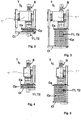
Figure 1 is a three-dimensional view of the new boring head (T) with protection hood (C) with bellows wall (Cp). -
Figure 2 shows a front view of the invention, with the hood (C) with bellows wall (Cp) completely contracted, whileFigure 3 shows a side view of the invention where the bellows wall (Cp) of the hood (C) is expanded. -
Figures 4 and 5 show two side views of the invention, with the bellows wall (Cp) of the hood (C) contracted and expanded, respectively. -
Figure 6 , instead, shows a three-dimensional view of a further possible embodiment of the new boring head (T), with protection hood (C) with telescopic wall (Cp). -
Figure 7 shows a front view of the invention, with the telescopic wall (Cp) of the hood (C) completely retracted, whileFigure 8 shows a side view of the invention where the telescopic wall (Cp) of the hood (C) is extended. -
Figures 9 and 10 show two side views of the invention, with the telescopic wall (Cp) of the hood (C) retracted and extended, respectively. - The hood (C) is connected, through apposite devices described and claimed below, to the body (T') of the boring head (T) and/or to other mechanical parts of the boring machine and is positioned near the drive units (T1, T2) where the boring rod and the covering tube are connected during the boring operation, that is, near the upper opening of the interspace between the boring rod and the covering tube.
- Said boring rod and said covering tube are respectively connected to and made integral with the corresponding couplings or drive units (T1, T2), for example through screwing, said couplings or drive units being in turn connected to at least one drive shaft (B) that transmits the rotary motion generated by the motor.
- Said boring rod and said covering tube are coaxial and between them there is an interspace through which the waste fluid consisting of debris mixed with water/air flows, said water/air being injected into said hollow rod during the boring operation; the waste fluid flow is then conveyed outside through the upper opening of said interspace.
- One or more supports (P) of one or more pistons or other devices (Pa) suited to cause, as described below, the expansion/contraction of said hood (C) are fixed to and integral with the body (T') of said boring head (T).
- Said devices, in this particular case shown in the figures, are pneumatic-hydraulic pistons (Pa) suited to cause the translation, in a direction substantially parallel to the axis of said shaft (B), of the bottom element (Ci) of said hood (C).
- Said hood (C) comprises, in addition to the bottom element (Ci) that translates vertically, also at least one screen or wall (Cp), preferably tubular with a circular section, for example, whose bottom is fixed to said element (Ci) and whose top is fixed to a further element (Cs) that is connected to and integral with the body (T') of said boring head (T).
- The operation of said pistons or devices (Pa) thus causes the translation of said bottom element (Ci) of the hood (C), but not of said fixed top element (Cs).
- Said screen or wall (Cp) is extensible, for example it can be structured as a bellows (
Figure 1 ) or telescopic (Figure 6 ), which means that it is possible to increase/reduce the vertical extension of its surface. - During maintenance or during the connection/disconnection of said boring rod and covering tube, said pistons or devices (Pa) maintain said bottom element (Ci) in a raised position with respect to the connection point of said boring rod and covering tube to the corresponding drive units (T1, T2), so that the operators have free access during said operations (
Figures 2 and 4 ). - During the boring operation, before the waste fluid flows out of said upper opening of the interspace between the rod and the covering tube, said pistons or devices (Pa) are operated and cause the downward translation of said bottom element (Ci), thus determining the gradual extension of said screen or wall (Cp) of the hood (C), until said bottom element (Ci) is in a lower position with respect to said upper opening, that is, until said screen or wall (Cp) covers completely the opening itself, in such a way as to prevent the uncontrolled outflow of the waste fluid consisting of water/air mixed with debris in the surrounding area (
Figures 3 and 5 ). - Said waste fluid flowing out of said opening, in fact, thus meets the inner surface of said screen or wall (Cp) of said hood (C) and flows downwards due to gravity.
- Therefore, with reference to the above description and the attached drawings, the following claims are expressed.
Claims (4)
- Boring head (T) for boring machines, with couplings or drive units (T1, T2) for the rotation-translation of at least one boring rod and of at least one covering tube that are coaxial and hollow to allow the passage of pressurised water/air and the upward flow of the waste fluid consisting of water/air mixed with debris along the interspace between said rod and said covering tube, characterised by further comprising at least one protection screen or wall (Cp), completely enveloping said rod and said covering tube, suited to be placed near or at the level of the upper annular opening of said interspace, out of which said waste fluid flows, in such a way as to intercept said waste fluid flow in all directions and to convey it downwards, wherein
said screen or wall (Cp) can be extended vertically, due to the effect of the relative displacement of at least one element (Ci) fixed to the bottom of said screen or wall (Cp) with respect to at least one further element (Cs) fixed to the top in a direction substantially parallel to the drive shaft (B) transmitting the rotary motion to said boring head (T),
wherein said bottom element (Ci) translates in a direction that is substantially parallel to said rod while said top element (Cs) is fixed to and integral with said boring head (T) itself,
wherein it further comprises at least one mechanical and/or hydraulic and/or electric device (Pa) suited to cause and control said relative displacement of said bottom element (Ci) with respect to said top element (Cs), and wherein said displacement causes the vertical extension/retraction of said screen or wall (Cp), in order to cover/uncover said upper opening of said interspace. - Boring head (T) according to claim 1, characterized in that said device (Pa) is a pneumatic-hydraulic piston, fixed to said boring head (T) and/or to part of the motor through apposite supports (P).
- Boring head (T) according to the previous claims, characterized in that said screen or wall (Cp) is a bellows screen or wall and/or telescopic and/or elastic.
- Boring head (T) according to the previous claims, characterized in that said screen or wall (Cp) is tubular with a substantially circular section.
Priority Applications (2)
| Application Number | Priority Date | Filing Date | Title |
|---|---|---|---|
| PT67962126T PT2035652T (en) | 2006-07-04 | 2006-07-04 | Boring head with new protection hood |
| PL06796212T PL2035652T3 (en) | 2006-07-04 | 2006-07-04 | Boring head with new protection hood |
Applications Claiming Priority (1)
| Application Number | Priority Date | Filing Date | Title |
|---|---|---|---|
| PCT/IT2006/000511 WO2008004255A1 (en) | 2006-07-04 | 2006-07-04 | BORiNG HEAD WITH NEW PROTECTION HOOD |
Publications (2)
| Publication Number | Publication Date |
|---|---|
| EP2035652A1 EP2035652A1 (en) | 2009-03-18 |
| EP2035652B1 true EP2035652B1 (en) | 2020-01-22 |
Family
ID=37820503
Family Applications (1)
| Application Number | Title | Priority Date | Filing Date |
|---|---|---|---|
| EP06796212.6A Active EP2035652B1 (en) | 2006-07-04 | 2006-07-04 | Boring head with new protection hood |
Country Status (7)
| Country | Link |
|---|---|
| US (1) | US8210255B2 (en) |
| EP (1) | EP2035652B1 (en) |
| CA (1) | CA2656632C (en) |
| ES (1) | ES2776923T3 (en) |
| PL (1) | PL2035652T3 (en) |
| PT (1) | PT2035652T (en) |
| WO (1) | WO2008004255A1 (en) |
Families Citing this family (5)
| Publication number | Priority date | Publication date | Assignee | Title |
|---|---|---|---|---|
| CN103085035B (en) * | 2013-02-14 | 2015-07-29 | 赵楠 | Dust collector for impact drill |
| US20150167991A1 (en) * | 2015-02-27 | 2015-06-18 | Caterpillar Inc. | Dust containment assembly |
| CN104863535B (en) * | 2015-05-20 | 2017-11-10 | 山河智能装备股份有限公司 | A kind of down-the-hole hammer drill dust removal device |
| CN109162655A (en) * | 2018-11-06 | 2019-01-08 | 史振荣 | A kind of rock drill with dust reduction capability |
| IT201900010488A1 (en) * | 2019-06-28 | 2020-12-28 | Casagrande Spa | DRILLING HEAD |
Citations (19)
| Publication number | Priority date | Publication date | Assignee | Title |
|---|---|---|---|---|
| US2122517A (en) | 1937-01-02 | 1938-07-05 | Cleveland Rock Drill Co | Dust eliminator |
| US2702181A (en) | 1952-05-08 | 1955-02-15 | Forrest G Brown | Dust collector for use in overhead drilling |
| US3339435A (en) | 1964-10-13 | 1967-09-05 | Heitz Walter-Helmut | Device for drilling machines for collecting chipped material |
| US3834470A (en) | 1973-02-15 | 1974-09-10 | Ingersoll Rand Co | Flexible hood means |
| US3934661A (en) | 1974-08-14 | 1976-01-27 | The Black And Decker Manufacturing Company | Dust cup |
| DE3140776A1 (en) | 1981-10-14 | 1983-04-28 | Thomas 7000 Stuttgart Schönherr | Device for catching drilling dust and the like for power hand drills |
| US4434861A (en) | 1981-01-07 | 1984-03-06 | Howeth David Franklin | Dust conveying and collecting system and method |
| EP0295225A1 (en) | 1987-06-12 | 1988-12-14 | Lenarduzzi, Tiziana | Antiscattering device for the collection of waste material produced in the course of drilling, milling and similar operations, to be fitted on the relevant machine tools |
| JPH04237718A (en) * | 1991-01-17 | 1992-08-26 | R S Japan Reader:Kk | Muddy soil splash preventive device of excavating machine |
| FR2716822A1 (en) | 1994-03-02 | 1995-09-08 | Gonzalez Diez Joaquin | Dust collector for electric hand drill |
| US5688082A (en) | 1995-01-19 | 1997-11-18 | Richardson; Owen Lewis | Dust extractor |
| EP0865867A1 (en) | 1996-07-23 | 1998-09-23 | NITTOKU ENGINEERING Co., Ltd. | Machining device |
| JPH11165234A (en) | 1997-12-05 | 1999-06-22 | Nittoku Eng Co Ltd | Machine tool |
| US6199656B1 (en) | 1998-09-29 | 2001-03-13 | Sandvik Ab | Casing for noise attenuation in a rock drilling rig |
| US20030111266A1 (en) | 2000-03-15 | 2003-06-19 | Roach Leon T. | Concrete drilling system and related methods |
| JP2004332501A (en) | 2003-04-30 | 2004-11-25 | Toshikazu Sawada | Anti-mud-scattering device of excavator |
| WO2005090738A1 (en) | 2004-03-19 | 2005-09-29 | Comacchio S.R.L. | Drilling head with protective screen |
| JP2006022568A (en) | 2004-07-08 | 2006-01-26 | Kamishimagumi:Kk | Soundproofing device and processing device provided with the same |
| WO2006038851A1 (en) | 2004-10-07 | 2006-04-13 | Atlas Copco Rock Drills Ab | Sleeve arrangement |
Family Cites Families (12)
| Publication number | Priority date | Publication date | Assignee | Title |
|---|---|---|---|---|
| US2107552A (en) | 1937-09-01 | 1938-02-08 | Spencer Turbine Co | Hood for rock drills |
| SE220480C1 (en) | 1965-09-29 | 1968-05-14 | ||
| US3638737A (en) | 1970-01-13 | 1972-02-01 | David G Moates | Pneumatic drill noise muffler and dust removal apparatus |
| SU408012A1 (en) | 1970-12-07 | 1973-12-10 | Государственный институт проектированию , конструированию машин горнорудной промышленности | DEVICE FOR DRILLING BORES |
| GB1455634A (en) | 1974-04-05 | 1976-11-17 | Hollandsche Betongroep Nv | Piledriving |
| GB1584888A (en) | 1977-01-18 | 1981-02-18 | Salzgitter Maschinen Ag | Rock drilling apparatus |
| DE2930296A1 (en) | 1979-07-26 | 1981-02-19 | Hausherr & Soehne Rudolf | Rock drilling machine noise suppression - involves telescoping concertina folding covers encasing drill rods |
| US4319647A (en) | 1980-04-16 | 1982-03-16 | Browning Engineering Corporation | Flame drill channelling method and apparatus for reducing noise and dust levels |
| SU1585501A1 (en) | 1988-06-27 | 1990-08-15 | Б.А. Кирш | Device for preventing splashing of drilling mud |
| US5653561A (en) | 1993-07-23 | 1997-08-05 | May; Robert | Swarf boot |
| AT410356B (en) * | 2000-05-17 | 2003-04-25 | Voest Alpine Bergtechnik | DEVICE FOR SEALING A HOLE AND DRILLING DRILL SMALL OR. SOLVED DEGRADATION MATERIAL |
| KR200314983Y1 (en) | 2003-02-21 | 2003-06-02 | 정천복 | apparatus for intercepting inflow of surface water use folding tube |
-
2006
- 2006-07-04 WO PCT/IT2006/000511 patent/WO2008004255A1/en not_active Ceased
- 2006-07-04 PL PL06796212T patent/PL2035652T3/en unknown
- 2006-07-04 ES ES06796212T patent/ES2776923T3/en active Active
- 2006-07-04 US US12/305,995 patent/US8210255B2/en active Active
- 2006-07-04 EP EP06796212.6A patent/EP2035652B1/en active Active
- 2006-07-04 CA CA2656632A patent/CA2656632C/en active Active
- 2006-07-04 PT PT67962126T patent/PT2035652T/en unknown
Patent Citations (19)
| Publication number | Priority date | Publication date | Assignee | Title |
|---|---|---|---|---|
| US2122517A (en) | 1937-01-02 | 1938-07-05 | Cleveland Rock Drill Co | Dust eliminator |
| US2702181A (en) | 1952-05-08 | 1955-02-15 | Forrest G Brown | Dust collector for use in overhead drilling |
| US3339435A (en) | 1964-10-13 | 1967-09-05 | Heitz Walter-Helmut | Device for drilling machines for collecting chipped material |
| US3834470A (en) | 1973-02-15 | 1974-09-10 | Ingersoll Rand Co | Flexible hood means |
| US3934661A (en) | 1974-08-14 | 1976-01-27 | The Black And Decker Manufacturing Company | Dust cup |
| US4434861A (en) | 1981-01-07 | 1984-03-06 | Howeth David Franklin | Dust conveying and collecting system and method |
| DE3140776A1 (en) | 1981-10-14 | 1983-04-28 | Thomas 7000 Stuttgart Schönherr | Device for catching drilling dust and the like for power hand drills |
| EP0295225A1 (en) | 1987-06-12 | 1988-12-14 | Lenarduzzi, Tiziana | Antiscattering device for the collection of waste material produced in the course of drilling, milling and similar operations, to be fitted on the relevant machine tools |
| JPH04237718A (en) * | 1991-01-17 | 1992-08-26 | R S Japan Reader:Kk | Muddy soil splash preventive device of excavating machine |
| FR2716822A1 (en) | 1994-03-02 | 1995-09-08 | Gonzalez Diez Joaquin | Dust collector for electric hand drill |
| US5688082A (en) | 1995-01-19 | 1997-11-18 | Richardson; Owen Lewis | Dust extractor |
| EP0865867A1 (en) | 1996-07-23 | 1998-09-23 | NITTOKU ENGINEERING Co., Ltd. | Machining device |
| JPH11165234A (en) | 1997-12-05 | 1999-06-22 | Nittoku Eng Co Ltd | Machine tool |
| US6199656B1 (en) | 1998-09-29 | 2001-03-13 | Sandvik Ab | Casing for noise attenuation in a rock drilling rig |
| US20030111266A1 (en) | 2000-03-15 | 2003-06-19 | Roach Leon T. | Concrete drilling system and related methods |
| JP2004332501A (en) | 2003-04-30 | 2004-11-25 | Toshikazu Sawada | Anti-mud-scattering device of excavator |
| WO2005090738A1 (en) | 2004-03-19 | 2005-09-29 | Comacchio S.R.L. | Drilling head with protective screen |
| JP2006022568A (en) | 2004-07-08 | 2006-01-26 | Kamishimagumi:Kk | Soundproofing device and processing device provided with the same |
| WO2006038851A1 (en) | 2004-10-07 | 2006-04-13 | Atlas Copco Rock Drills Ab | Sleeve arrangement |
Non-Patent Citations (1)
| Title |
|---|
| FRED N. KISSELL: "Handbook for dust control in mining", NIOSH IC 9465, June 2003 (2003-06-01), XP055745818, Retrieved from the Internet <URL:https://www.cdc.gov/niosh/mining/UserFiles/works/pdfs/2003-147.pdf> |
Also Published As
| Publication number | Publication date |
|---|---|
| CA2656632C (en) | 2013-09-03 |
| WO2008004255A1 (en) | 2008-01-10 |
| US8210255B2 (en) | 2012-07-03 |
| CA2656632A1 (en) | 2008-01-10 |
| EP2035652A1 (en) | 2009-03-18 |
| US20100059282A1 (en) | 2010-03-11 |
| PL2035652T3 (en) | 2020-11-16 |
| ES2776923T3 (en) | 2020-08-03 |
| PT2035652T (en) | 2020-04-23 |
Similar Documents
| Publication | Publication Date | Title |
|---|---|---|
| CN110953013B (en) | Controllable jet flow punching pressure relief and permeability increase device and method for soft coal seam | |
| EP2949859B1 (en) | Safety system for controlling a dangerous area of an excavation machine and excavation machine comprising the same | |
| KR102106219B1 (en) | Bit for enlarging excavation hole | |
| KR102538953B1 (en) | Earth and sand removing apparatus of auger screw | |
| EP1118718A2 (en) | Rotary displacement piling equipment | |
| EP2035652B1 (en) | Boring head with new protection hood | |
| CN207176684U (en) | A kind of self-cleaning type screw pile driver | |
| JP2005016300A (en) | Underground borehole excavating method and wet boring tool | |
| WO2011037659A1 (en) | Falling object protection system | |
| AU2020231598B2 (en) | Fluid collecting device and method | |
| CN104564094B (en) | A kind of shield machine cutter head nozzle anti-block apparatus | |
| CN112879012A (en) | Hole protecting device | |
| JP3839819B2 (en) | Reverse circulation drill | |
| US7523793B2 (en) | Drilling head with protective screen | |
| CN214577004U (en) | hole guard | |
| KR101576973B1 (en) | Reverse Circulation Drill System | |
| KR20130106936A (en) | Apparatus of discharging slime using drills for underground excavation and metohd thereof | |
| KR102846088B1 (en) | Earth and sand removing apparatus of auger screw | |
| KR102841703B1 (en) | Earth and sand removing apparatus of auger screw | |
| CN106076992A (en) | Conveying pipe cleaning plant | |
| KR102119658B1 (en) | Blind Type Leader for Air Hammer Excavating Equipment | |
| CN214943964U (en) | Foldable ground bullet drilling device for water treatment site | |
| JP2009144366A (en) | Joint device for use in pile pressing-in apparatus | |
| KR20210150746A (en) | Kelly bar with multi-stage piping for remicon injection and spraying solidifying agent | |
| RU2795402C2 (en) | Assembly for expansion of a drilling system shaft |
Legal Events
| Date | Code | Title | Description |
|---|---|---|---|
| PUAI | Public reference made under article 153(3) epc to a published international application that has entered the european phase |
Free format text: ORIGINAL CODE: 0009012 |
|
| 17P | Request for examination filed |
Effective date: 20090109 |
|
| AK | Designated contracting states |
Kind code of ref document: A1 Designated state(s): AT BE BG CH CY CZ DE DK EE ES FI FR GB GR HU IE IS IT LI LT LU LV MC NL PL PT RO SE SI SK TR |
|
| AX | Request for extension of the european patent |
Extension state: AL BA HR MK RS |
|
| 17Q | First examination report despatched |
Effective date: 20090506 |
|
| DAX | Request for extension of the european patent (deleted) | ||
| TPAC | Observations filed by third parties |
Free format text: ORIGINAL CODE: EPIDOSNTIPA |
|
| TPAC | Observations filed by third parties |
Free format text: ORIGINAL CODE: EPIDOSNTIPA |
|
| STAA | Information on the status of an ep patent application or granted ep patent |
Free format text: STATUS: EXAMINATION IS IN PROGRESS |
|
| TPAC | Observations filed by third parties |
Free format text: ORIGINAL CODE: EPIDOSNTIPA |
|
| TPAC | Observations filed by third parties |
Free format text: ORIGINAL CODE: EPIDOSNTIPA |
|
| TPAC | Observations filed by third parties |
Free format text: ORIGINAL CODE: EPIDOSNTIPA |
|
| GRAP | Despatch of communication of intention to grant a patent |
Free format text: ORIGINAL CODE: EPIDOSNIGR1 |
|
| STAA | Information on the status of an ep patent application or granted ep patent |
Free format text: STATUS: GRANT OF PATENT IS INTENDED |
|
| GRAS | Grant fee paid |
Free format text: ORIGINAL CODE: EPIDOSNIGR3 |
|
| INTG | Intention to grant announced |
Effective date: 20191122 |
|
| GRAA | (expected) grant |
Free format text: ORIGINAL CODE: 0009210 |
|
| STAA | Information on the status of an ep patent application or granted ep patent |
Free format text: STATUS: THE PATENT HAS BEEN GRANTED |
|
| AK | Designated contracting states |
Kind code of ref document: B1 Designated state(s): AT BE BG CH CY CZ DE DK EE ES FI FR GB GR HU IE IS IT LI LT LU LV MC NL PL PT RO SE SI SK TR |
|
| REG | Reference to a national code |
Ref country code: GB Ref legal event code: FG4D |
|
| REG | Reference to a national code |
Ref country code: CH Ref legal event code: EP |
|
| REG | Reference to a national code |
Ref country code: AT Ref legal event code: REF Ref document number: 1227017 Country of ref document: AT Kind code of ref document: T Effective date: 20200215 |
|
| REG | Reference to a national code |
Ref country code: IE Ref legal event code: FG4D |
|
| REG | Reference to a national code |
Ref country code: DE Ref legal event code: R096 Ref document number: 602006059084 Country of ref document: DE |
|
| REG | Reference to a national code |
Ref country code: SE Ref legal event code: TRGR |
|
| REG | Reference to a national code |
Ref country code: RO Ref legal event code: EPE |
|
| REG | Reference to a national code |
Ref country code: PT Ref legal event code: SC4A Ref document number: 2035652 Country of ref document: PT Date of ref document: 20200423 Kind code of ref document: T Free format text: AVAILABILITY OF NATIONAL TRANSLATION Effective date: 20200416 Ref country code: FI Ref legal event code: FGE |
|
| REG | Reference to a national code |
Ref country code: NL Ref legal event code: FP |
|
| REG | Reference to a national code |
Ref country code: LT Ref legal event code: MG4D |
|
| REG | Reference to a national code |
Ref country code: ES Ref legal event code: FG2A Ref document number: 2776923 Country of ref document: ES Kind code of ref document: T3 Effective date: 20200803 |
|
| PG25 | Lapsed in a contracting state [announced via postgrant information from national office to epo] |
Ref country code: LV Free format text: LAPSE BECAUSE OF FAILURE TO SUBMIT A TRANSLATION OF THE DESCRIPTION OR TO PAY THE FEE WITHIN THE PRESCRIBED TIME-LIMIT Effective date: 20200122 Ref country code: IS Free format text: LAPSE BECAUSE OF FAILURE TO SUBMIT A TRANSLATION OF THE DESCRIPTION OR TO PAY THE FEE WITHIN THE PRESCRIBED TIME-LIMIT Effective date: 20200522 Ref country code: BG Free format text: LAPSE BECAUSE OF FAILURE TO SUBMIT A TRANSLATION OF THE DESCRIPTION OR TO PAY THE FEE WITHIN THE PRESCRIBED TIME-LIMIT Effective date: 20200422 Ref country code: GR Free format text: LAPSE BECAUSE OF FAILURE TO SUBMIT A TRANSLATION OF THE DESCRIPTION OR TO PAY THE FEE WITHIN THE PRESCRIBED TIME-LIMIT Effective date: 20200423 |
|
| REG | Reference to a national code |
Ref country code: DE Ref legal event code: R026 Ref document number: 602006059084 Country of ref document: DE |
|
| PLBI | Opposition filed |
Free format text: ORIGINAL CODE: 0009260 |
|
| PG25 | Lapsed in a contracting state [announced via postgrant information from national office to epo] |
Ref country code: SK Free format text: LAPSE BECAUSE OF FAILURE TO SUBMIT A TRANSLATION OF THE DESCRIPTION OR TO PAY THE FEE WITHIN THE PRESCRIBED TIME-LIMIT Effective date: 20200122 Ref country code: DK Free format text: LAPSE BECAUSE OF FAILURE TO SUBMIT A TRANSLATION OF THE DESCRIPTION OR TO PAY THE FEE WITHIN THE PRESCRIBED TIME-LIMIT Effective date: 20200122 Ref country code: LT Free format text: LAPSE BECAUSE OF FAILURE TO SUBMIT A TRANSLATION OF THE DESCRIPTION OR TO PAY THE FEE WITHIN THE PRESCRIBED TIME-LIMIT Effective date: 20200122 Ref country code: EE Free format text: LAPSE BECAUSE OF FAILURE TO SUBMIT A TRANSLATION OF THE DESCRIPTION OR TO PAY THE FEE WITHIN THE PRESCRIBED TIME-LIMIT Effective date: 20200122 |
|
| 26 | Opposition filed |
Opponent name: CASAGRANDE SPA Effective date: 20201021 |
|
| REG | Reference to a national code |
Ref country code: FI Ref legal event code: MDE Opponent name: CASAGRANDE SPA |
|
| PLAX | Notice of opposition and request to file observation + time limit sent |
Free format text: ORIGINAL CODE: EPIDOSNOBS2 |
|
| PG25 | Lapsed in a contracting state [announced via postgrant information from national office to epo] |
Ref country code: MC Free format text: LAPSE BECAUSE OF FAILURE TO SUBMIT A TRANSLATION OF THE DESCRIPTION OR TO PAY THE FEE WITHIN THE PRESCRIBED TIME-LIMIT Effective date: 20200122 Ref country code: SI Free format text: LAPSE BECAUSE OF FAILURE TO SUBMIT A TRANSLATION OF THE DESCRIPTION OR TO PAY THE FEE WITHIN THE PRESCRIBED TIME-LIMIT Effective date: 20200122 |
|
| REG | Reference to a national code |
Ref country code: CH Ref legal event code: NV Representative=s name: VALIPAT S.A. C/O BOVARD SA NEUCHATEL, CH |
|
| PG25 | Lapsed in a contracting state [announced via postgrant information from national office to epo] |
Ref country code: LU Free format text: LAPSE BECAUSE OF NON-PAYMENT OF DUE FEES Effective date: 20200704 Ref country code: IE Free format text: LAPSE BECAUSE OF NON-PAYMENT OF DUE FEES Effective date: 20200704 |
|
| PLBB | Reply of patent proprietor to notice(s) of opposition received |
Free format text: ORIGINAL CODE: EPIDOSNOBS3 |
|
| REG | Reference to a national code |
Ref country code: AT Ref legal event code: UEP Ref document number: 1227017 Country of ref document: AT Kind code of ref document: T Effective date: 20200122 |
|
| PG25 | Lapsed in a contracting state [announced via postgrant information from national office to epo] |
Ref country code: TR Free format text: LAPSE BECAUSE OF FAILURE TO SUBMIT A TRANSLATION OF THE DESCRIPTION OR TO PAY THE FEE WITHIN THE PRESCRIBED TIME-LIMIT Effective date: 20200122 Ref country code: CY Free format text: LAPSE BECAUSE OF FAILURE TO SUBMIT A TRANSLATION OF THE DESCRIPTION OR TO PAY THE FEE WITHIN THE PRESCRIBED TIME-LIMIT Effective date: 20200122 |
|
| PLCK | Communication despatched that opposition was rejected |
Free format text: ORIGINAL CODE: EPIDOSNREJ1 |
|
| APAH | Appeal reference modified |
Free format text: ORIGINAL CODE: EPIDOSCREFNO |
|
| APBM | Appeal reference recorded |
Free format text: ORIGINAL CODE: EPIDOSNREFNO |
|
| APBP | Date of receipt of notice of appeal recorded |
Free format text: ORIGINAL CODE: EPIDOSNNOA2O |
|
| APBQ | Date of receipt of statement of grounds of appeal recorded |
Free format text: ORIGINAL CODE: EPIDOSNNOA3O |
|
| REG | Reference to a national code |
Ref country code: DE Ref legal event code: R100 Ref document number: 602006059084 Country of ref document: DE |
|
| APBU | Appeal procedure closed |
Free format text: ORIGINAL CODE: EPIDOSNNOA9O |
|
| PLBN | Opposition rejected |
Free format text: ORIGINAL CODE: 0009273 |
|
| STAA | Information on the status of an ep patent application or granted ep patent |
Free format text: STATUS: OPPOSITION REJECTED |
|
| 27O | Opposition rejected |
Effective date: 20240703 |
|
| REG | Reference to a national code |
Ref country code: FI Ref legal event code: FGE |
|
| PGFP | Annual fee paid to national office [announced via postgrant information from national office to epo] |
Ref country code: PL Payment date: 20250620 Year of fee payment: 20 |
|
| PGFP | Annual fee paid to national office [announced via postgrant information from national office to epo] |
Ref country code: IT Payment date: 20250526 Year of fee payment: 20 |
|
| PGFP | Annual fee paid to national office [announced via postgrant information from national office to epo] |
Ref country code: PT Payment date: 20250626 Year of fee payment: 20 |
|
| PGFP | Annual fee paid to national office [announced via postgrant information from national office to epo] |
Ref country code: CZ Payment date: 20250620 Year of fee payment: 20 |
|
| PGFP | Annual fee paid to national office [announced via postgrant information from national office to epo] |
Ref country code: NL Payment date: 20250726 Year of fee payment: 20 |
|
| PGFP | Annual fee paid to national office [announced via postgrant information from national office to epo] |
Ref country code: ES Payment date: 20250801 Year of fee payment: 20 Ref country code: FI Payment date: 20250725 Year of fee payment: 20 |
|
| PGFP | Annual fee paid to national office [announced via postgrant information from national office to epo] |
Ref country code: DE Payment date: 20250729 Year of fee payment: 20 |
|
| PGFP | Annual fee paid to national office [announced via postgrant information from national office to epo] |
Ref country code: BE Payment date: 20250728 Year of fee payment: 20 Ref country code: GB Payment date: 20250728 Year of fee payment: 20 |
|
| PGFP | Annual fee paid to national office [announced via postgrant information from national office to epo] |
Ref country code: AT Payment date: 20250620 Year of fee payment: 20 Ref country code: FR Payment date: 20250725 Year of fee payment: 20 |
|
| PGFP | Annual fee paid to national office [announced via postgrant information from national office to epo] |
Ref country code: SE Payment date: 20250727 Year of fee payment: 20 Ref country code: CH Payment date: 20250801 Year of fee payment: 20 |
|
| PGFP | Annual fee paid to national office [announced via postgrant information from national office to epo] |
Ref country code: RO Payment date: 20250701 Year of fee payment: 20 |