EP2033592A1 - Steuerungsvorrichtung und Verfahren zur Steuerung einer medizinische Diagnostik- und/oder Therapieanlage sowie medizinische Diagnostik- und/oder Therapieanlage - Google Patents
Steuerungsvorrichtung und Verfahren zur Steuerung einer medizinische Diagnostik- und/oder Therapieanlage sowie medizinische Diagnostik- und/oder Therapieanlage Download PDFInfo
- Publication number
- EP2033592A1 EP2033592A1 EP08104814A EP08104814A EP2033592A1 EP 2033592 A1 EP2033592 A1 EP 2033592A1 EP 08104814 A EP08104814 A EP 08104814A EP 08104814 A EP08104814 A EP 08104814A EP 2033592 A1 EP2033592 A1 EP 2033592A1
- Authority
- EP
- European Patent Office
- Prior art keywords
- control
- control unit
- mobile hand
- predefined location
- controllable
- Prior art date
- Legal status (The legal status is an assumption and is not a legal conclusion. Google has not performed a legal analysis and makes no representation as to the accuracy of the status listed.)
- Granted
Links
Images

Classifications
-
- G—PHYSICS
- G16—INFORMATION AND COMMUNICATION TECHNOLOGY [ICT] SPECIALLY ADAPTED FOR SPECIFIC APPLICATION FIELDS
- G16H—HEALTHCARE INFORMATICS, i.e. INFORMATION AND COMMUNICATION TECHNOLOGY [ICT] SPECIALLY ADAPTED FOR THE HANDLING OR PROCESSING OF MEDICAL OR HEALTHCARE DATA
- G16H40/00—ICT specially adapted for the management or administration of healthcare resources or facilities; ICT specially adapted for the management or operation of medical equipment or devices
- G16H40/60—ICT specially adapted for the management or administration of healthcare resources or facilities; ICT specially adapted for the management or operation of medical equipment or devices for the operation of medical equipment or devices
- G16H40/67—ICT specially adapted for the management or administration of healthcare resources or facilities; ICT specially adapted for the management or operation of medical equipment or devices for the operation of medical equipment or devices for remote operation
-
- A—HUMAN NECESSITIES
- A61—MEDICAL OR VETERINARY SCIENCE; HYGIENE
- A61B—DIAGNOSIS; SURGERY; IDENTIFICATION
- A61B34/00—Computer-aided surgery; Manipulators or robots specially adapted for use in surgery
- A61B34/70—Manipulators specially adapted for use in surgery
- A61B34/74—Manipulators with manual electric input means
-
- A—HUMAN NECESSITIES
- A61—MEDICAL OR VETERINARY SCIENCE; HYGIENE
- A61B—DIAGNOSIS; SURGERY; IDENTIFICATION
- A61B6/00—Apparatus or devices for radiation diagnosis; Apparatus or devices for radiation diagnosis combined with radiation therapy equipment
-
- A—HUMAN NECESSITIES
- A61—MEDICAL OR VETERINARY SCIENCE; HYGIENE
- A61B—DIAGNOSIS; SURGERY; IDENTIFICATION
- A61B6/00—Apparatus or devices for radiation diagnosis; Apparatus or devices for radiation diagnosis combined with radiation therapy equipment
- A61B6/10—Safety means specially adapted therefor
-
- A—HUMAN NECESSITIES
- A61—MEDICAL OR VETERINARY SCIENCE; HYGIENE
- A61B—DIAGNOSIS; SURGERY; IDENTIFICATION
- A61B6/00—Apparatus or devices for radiation diagnosis; Apparatus or devices for radiation diagnosis combined with radiation therapy equipment
- A61B6/44—Constructional features of apparatus for radiation diagnosis
- A61B6/4411—Constructional features of apparatus for radiation diagnosis the apparatus being modular
-
- A—HUMAN NECESSITIES
- A61—MEDICAL OR VETERINARY SCIENCE; HYGIENE
- A61B—DIAGNOSIS; SURGERY; IDENTIFICATION
- A61B6/00—Apparatus or devices for radiation diagnosis; Apparatus or devices for radiation diagnosis combined with radiation therapy equipment
- A61B6/54—Control of apparatus or devices for radiation diagnosis
- A61B6/548—Remote control of the apparatus or devices
-
- A—HUMAN NECESSITIES
- A61—MEDICAL OR VETERINARY SCIENCE; HYGIENE
- A61B—DIAGNOSIS; SURGERY; IDENTIFICATION
- A61B6/00—Apparatus or devices for radiation diagnosis; Apparatus or devices for radiation diagnosis combined with radiation therapy equipment
- A61B6/58—Testing, adjusting or calibrating thereof
- A61B6/581—Remote testing
-
- A—HUMAN NECESSITIES
- A61—MEDICAL OR VETERINARY SCIENCE; HYGIENE
- A61B—DIAGNOSIS; SURGERY; IDENTIFICATION
- A61B90/00—Instruments, implements or accessories specially adapted for surgery or diagnosis and not covered by any of the groups A61B1/00 - A61B50/00, e.g. for luxation treatment or for protecting wound edges
-
- G—PHYSICS
- G08—SIGNALLING
- G08C—TRANSMISSION SYSTEMS FOR MEASURED VALUES, CONTROL OR SIMILAR SIGNALS
- G08C17/00—Arrangements for transmitting signals characterised by the use of a wireless electrical link
-
- G—PHYSICS
- G16—INFORMATION AND COMMUNICATION TECHNOLOGY [ICT] SPECIALLY ADAPTED FOR SPECIFIC APPLICATION FIELDS
- G16H—HEALTHCARE INFORMATICS, i.e. INFORMATION AND COMMUNICATION TECHNOLOGY [ICT] SPECIALLY ADAPTED FOR THE HANDLING OR PROCESSING OF MEDICAL OR HEALTHCARE DATA
- G16H20/00—ICT specially adapted for therapies or health-improving plans, e.g. for handling prescriptions, for steering therapy or for monitoring patient compliance
- G16H20/40—ICT specially adapted for therapies or health-improving plans, e.g. for handling prescriptions, for steering therapy or for monitoring patient compliance relating to mechanical, radiation or invasive therapies, e.g. surgery, laser therapy, dialysis or acupuncture
-
- H—ELECTRICITY
- H04—ELECTRIC COMMUNICATION TECHNIQUE
- H04B—TRANSMISSION
- H04B1/00—Details of transmission systems, not covered by a single one of groups H04B3/00 - H04B13/00; Details of transmission systems not characterised by the medium used for transmission
- H04B1/06—Receivers
- H04B1/16—Circuits
- H04B1/20—Circuits for coupling gramophone pick-up, recorder output, or microphone to receiver
- H04B1/202—Circuits for coupling gramophone pick-up, recorder output, or microphone to receiver by remote control
-
- A—HUMAN NECESSITIES
- A61—MEDICAL OR VETERINARY SCIENCE; HYGIENE
- A61B—DIAGNOSIS; SURGERY; IDENTIFICATION
- A61B17/00—Surgical instruments, devices or methods
- A61B2017/00017—Electrical control of surgical instruments
- A61B2017/00212—Electrical control of surgical instruments using remote controls
-
- A—HUMAN NECESSITIES
- A61—MEDICAL OR VETERINARY SCIENCE; HYGIENE
- A61B—DIAGNOSIS; SURGERY; IDENTIFICATION
- A61B34/00—Computer-aided surgery; Manipulators or robots specially adapted for use in surgery
- A61B34/20—Surgical navigation systems; Devices for tracking or guiding surgical instruments, e.g. for frameless stereotaxis
- A61B2034/2046—Tracking techniques
- A61B2034/2051—Electromagnetic tracking systems
-
- A—HUMAN NECESSITIES
- A61—MEDICAL OR VETERINARY SCIENCE; HYGIENE
- A61B—DIAGNOSIS; SURGERY; IDENTIFICATION
- A61B34/00—Computer-aided surgery; Manipulators or robots specially adapted for use in surgery
- A61B34/20—Surgical navigation systems; Devices for tracking or guiding surgical instruments, e.g. for frameless stereotaxis
-
- A—HUMAN NECESSITIES
- A61—MEDICAL OR VETERINARY SCIENCE; HYGIENE
- A61N—ELECTROTHERAPY; MAGNETOTHERAPY; RADIATION THERAPY; ULTRASOUND THERAPY
- A61N5/00—Radiation therapy
- A61N5/10—X-ray therapy; Gamma-ray therapy; Particle-irradiation therapy
- A61N5/1048—Monitoring, verifying, controlling systems and methods
- A61N2005/1074—Details of the control system, e.g. user interfaces
-
- A—HUMAN NECESSITIES
- A61—MEDICAL OR VETERINARY SCIENCE; HYGIENE
- A61N—ELECTROTHERAPY; MAGNETOTHERAPY; RADIATION THERAPY; ULTRASOUND THERAPY
- A61N5/00—Radiation therapy
- A61N5/10—X-ray therapy; Gamma-ray therapy; Particle-irradiation therapy
- A61N2005/1085—X-ray therapy; Gamma-ray therapy; Particle-irradiation therapy characterised by the type of particles applied to the patient
- A61N2005/1087—Ions; Protons
Definitions
- the invention relates to a control device for a medical diagnostic and / or therapeutic system and a method for controlling such. Furthermore, the invention relates to a medical diagnostic and / or therapeutic system with such a control device.
- the subject of the invention is used in particular in the context of particle therapy, in which a large number of controllable elements must be coordinated with one another.
- Particle therapy is an established method for the treatment of tissue, in particular tumor diseases.
- Irradiation methods such as those used in particle therapy, are also used in non-therapeutic areas. These include, for example, research work in the context of particle therapy, which are performed on non-living phantoms or bodies, irradiation of materials, etc.
- charged particles are accelerated to high energies, formed into a particle beam and guided over a high-energy beam transport system to one or more treatment rooms , In one of these irradiation rooms, the object to be irradiated is irradiated with the particle beam.
- a part of the control processes of a particle therapy system can be carried out by a user using a mobile hand control unit.
- a hand control unit can be advantageously used.
- a user can operate the patient positioning device on which the patient is located via the hand-held control unit or make adjustments to the particle therapy system via the hand-held control unit.
- the mobile hand control unit has the advantage that the user can perform the control of different locations, for example in the immediate vicinity of the patient, without having to go to a permanently installed control unit.
- the object of the invention is achieved by a control device for a medical diagnostic and / or therapeutic system according to claim 1, by a medical diagnostic and / or therapeutic system according to claim 8 and by a Method for controlling a medical diagnostic and / or therapeutic system according to claim 9.
- control operations are thus disabled and can not be performed by the control unit unless the mobile handset is in the predefined location. In this way, the safety in operating the medical diagnostic and / or therapy system is increased compared to a system in which such a control mechanism is not available.
- the mobile hand control unit may inadvertently be damaged or even manipulated to inadvertently generate control commands. For example, if the mobile hand-held unit on a patient couch is forgotten and the user subsequently leaves the room for an imaging examination or an irradiation session to start, it is possible that the hand-held unit may be exposed by X-rays or by the treatment beam is damaged or that malfunctions are triggered. This can lead to a significant impairment of safety.
- the control device ensures that the mobile hand-held control unit is located at a predefined location before certain control operations can be performed by the control unit. In this way it can be ensured that the mobile hand control unit is not damaged by a control of the medical diagnostic and / or therapy system. The safety in operating the medical diagnostic and / or therapy system and in particular patient safety are thereby significantly increased.
- the predefined location within the medical diagnostic and / or therapeutic facility may be e.g. located within a diagnostic and / or therapy room, in particular outside the range of moving elements within the diagnostic and / or therapy room and / or in particular outside the effective range of diagnostic and / or therapeutic devices.
- the predefined location can also be located, for example, outside the diagnostic and / or therapy room.
- the control unit is usually located outside the diagnostic and / or therapy room.
- control device - and in particular the control unit - need not be a single self-contained unit. It may also comprise several distributed subunits, each of which controls different elements.
- the control device comprises a position monitoring system, with which it can be determined whether the mobile hand-held unit is located at the predefined location or not.
- a position monitoring system or location system known position monitoring systems or location systems can be used be, for example, with electromagnetic waves or acoustic waves operating position monitoring systems.
- the position monitoring can take place continuously or only selectively, i. immediately upon the execution of the control action, which is feasible only when the mobile hand-held unit is in the predefined location.
- control device may have a holding device for the mobile hand-operated part.
- the predefined location then corresponds to the space in the mounting device. This means that the part of the control operations is only feasible when the mobile hand control unit is in the mounting device. In this way it can be ensured in a simple manner that the mobile hand-held control unit is in its correct position.
- the mobile hand control unit is designed in particular as a cordless hand control unit, so that control commands of the manual control unit are transmitted wirelessly to a control unit.
- the part of the control operations that can be executed by the control unit only when the mobile hand control unit is located at the predefined location can include a control of the controllable element that can be controlled by a user with the mobile hand control unit.
- a hierarchy of control of the controllable element can be easily controlled.
- control of the controllable element is blocked by the control unit.
- the controllable element can then be operated in regular operation only by the mobile hand control unit. Only when the mobile hand control unit at the predefined Location - for example, in a mounting device - is located, the control of the controllable element can be taken over by the control unit.
- the controllable element may in particular be a movable element in a diagnostic and / or therapy room, in particular a patient positioning device and / or an imaging device.
- the movable element can be a gantry, which can be rotated in particular around an irradiation space.
- the part of the control operations that is executable by the control unit only when the mobile hand control unit is at the predefined location may include control from another controllable element that is not controlled by a user with the mobile hand control unit can be.
- a hierarchy of control of various elements controlled by different units - the mobile hand-held unit and the control unit - can be easily controlled so as to increase the safety in the control of the medical diagnostic and / or therapy system .
- Controllable elements which can not usually be controlled by a mobile hand control unit via control processes, are in particulate therapy, in particular accelerator units for acceleration of particles, a high-energy beam transport system, etc.
- the control device is designed as a control device for a particle therapy system, wherein one of the control operations of the control unit is the delivery of a beam release signal.
- a beam enable signal is usually present in a particle therapy system if all relevant safety checks have been carried out before a planned irradiation. Only in the presence of a beam release signal can actually take place irradiation of an object to be irradiated.
- a beam release signal can only be emitted by the control unit when the mobile hand control unit is located at the predefined location. In this way it is ensured that the mobile hand control unit is not mistakenly forgotten in the area of the treatment beam, so that it would be damaged during a subsequent irradiation.
- the medical diagnostic and / or therapeutic system comprises a diagnostic or therapy device, which is controlled by a control device according to one of claims 1 to 7, as well as the controllable element, which is controlled by the mobile hand control part of the control device.
- a plurality of control operations for controlling the medical diagnostic and / or therapeutic system are performed.
- the method for controlling is designed such that a part of the control operations can only be carried out when a mobile hand-held control unit, with which at least one controllable element can be controlled by a user, is located at a predefined location.
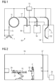
- Fig. 1 shows a schematic overview of the structure of a particle therapy system 10.
- a particle therapy system 10 takes place in particular irradiation of a body, in particular a tumor-affected tissue, with a particle beam.
- particles mainly ions such as protons, pions, helium ions, carbon ions or other types of ions are used.
- ions are generated in a particle source 11.
- two particle sources 11 are present, which produce two different types of ions can be switched between these two ion species within a short time interval.
- a solenoid 12 is used, which is arranged between the ion sources 11 on the one hand and a pre-accelerator 13 on the other.
- this allows the particle therapy system 10 to be operated simultaneously with protons and with carbon ions.
- the ions generated by the or one of the ion sources 11 and optionally selected by the switching magnet 12 are accelerated in the pre-accelerator 13 to a first energy level.
- the pre-accelerator 13 is, for example, a linear accelerator (LINAC for English: "LINear ACcelerator”).
- the particles are fed into an accelerator 15, for example a synchrotron or cyclotron.
- an accelerator 15 for example a synchrotron or cyclotron.
- they are accelerated to high energies necessary for irradiation.
- a high-energy beam transport system 17 guides the particle beam to one or more irradiation spaces 19.
- an irradiation space 19 the accelerated particles are directed onto a body to be irradiated. Depending on the configuration, this takes place from a fixed direction (in so-called "fixed beam” spaces) or else via a rotatable gantry 21 which can be moved about an axis 22 from different directions.
- FIG. 1 The basis of the FIG. 1
- the illustrated basic construction of a particle therapy system 10 is typical for many particle therapy systems, but may also deviate therefrom; For example, depending on the acceleration of the particles, an irradiation device need not be arranged as a particle therapy system.
- the particle therapy system 10 comprises a multiplicity of controllable elements which extend both outside irradiation spaces 19 - such as, for example, the accelerator and beam guiding components - as well as within irradiation spaces 19 - e.g. Patient positioning devices and imaging devices - are located.
- the controllable elements are controlled, inter alia, by a control unit 23.
- the control unit 23 does not have to be constructed as a single closed unit, but may comprise a plurality of subunits, each of which controls different controllable elements.
- Fig. 2 2 shows a schematic overview of an irradiation space 19.
- an object to be irradiated eg a patient 25
- the positioning device 27 can additionally be wirelessly controlled by a user 31 by means of a mobile hand control part 33. This allows a user 31, for example, to stay close to the patient 25, for example to supply the patient 25, and at the same time to control the positioning device 27.
- a holding device 35 for the mobile hand control part 33 which at the same time is a charging shell for the mobile hand control part 33, so that a rechargeable battery of the mobile hand control part 33 can be charged.
- the holding device 35 is designed such that it detects whether the mobile hand control part 33 is located in the holding device 35 or not. This information is provided to the control unit 23. Certain control operations performed by the control unit 23 may be performed by the control unit 23 only when the mobile hand control part 33 is in the holder device 35.
- One of these control operations may be, for example, the delivery of a beam enable signal from the control unit 23.
- a beam enable signal causes a particle beam to be actually directed at an object to be irradiated. Without the presence of a beam enable signal, the application of a particle beam is blocked.
- the mobile handset 33 must be located at a predefined location - as shown here in the fixture 35 - to enable a beam enable signal.
- other conditions must usually be met in order for a beam enable signal to be delivered, such as the proper functioning of acceleration and beam guidance components. In this way, it is ensured that the mobile hand control part 33 is in a safe place before irradiation begins and is not inadvertently forgotten near the patient 25, ie near the particle beam.
- Another of these control operations may be, for example, the control of the positioning device 27 by the control unit 23.
- the positioning device 27 can be controlled by the control unit 23 only when the mobile hand-held unit 33 is at the predefined location. In this way, it is ensured that in a control of the positioning device 27 no conflicting control commands are given, since a hierarchy with respect to the control of the positioning device 27 is clearly defined.
- the position of the mobile hand control part 33 can be determined, for example, by a position monitoring system 37 located in the irradiation room.
- Fig. 3 shows a schematic overview of control operations that are performed to control a medical diagnostic and / or therapy system.
- control operations 41, 41 'can be performed.
- control operations 41 'can only be executed when a certain condition 45 is present. This condition is given when a mobile hand control unit, with which a controllable element of the medical diagnostic and / or therapeutic system is controlled, is located at a predefined location within the medical diagnostic and / or therapy system. As long as this condition 45 is not fulfilled, the control operations 41 'belonging to the part 43 can not be activated.
- the control operations 41 'belonging to the part 43 can be control processes which control the controllable element, which can likewise be controlled by the mobile hand control part.
- the control operations associated with the part can also control operations be controlled with which further controllable elements whose control can not be made by the mobile hand control unit.
Landscapes
- Health & Medical Sciences (AREA)
- Engineering & Computer Science (AREA)
- Life Sciences & Earth Sciences (AREA)
- Medical Informatics (AREA)
- Surgery (AREA)
- Biomedical Technology (AREA)
- Public Health (AREA)
- General Health & Medical Sciences (AREA)
- Nuclear Medicine, Radiotherapy & Molecular Imaging (AREA)
- Animal Behavior & Ethology (AREA)
- Heart & Thoracic Surgery (AREA)
- Molecular Biology (AREA)
- Veterinary Medicine (AREA)
- Physics & Mathematics (AREA)
- Pathology (AREA)
- Radiology & Medical Imaging (AREA)
- Optics & Photonics (AREA)
- High Energy & Nuclear Physics (AREA)
- Biophysics (AREA)
- Epidemiology (AREA)
- Primary Health Care (AREA)
- Computer Networks & Wireless Communication (AREA)
- Robotics (AREA)
- General Business, Economics & Management (AREA)
- Oral & Maxillofacial Surgery (AREA)
- Business, Economics & Management (AREA)
- General Physics & Mathematics (AREA)
- Urology & Nephrology (AREA)
- Signal Processing (AREA)
- Radiation-Therapy Devices (AREA)
Abstract
Description
- Die Erfindung betrifft eine Steuerungsvorrichtung für eine medizinische Diagnostik- und/oder Therapieanlage sowie ein Verfahren zur Steuerung einer solchen. Weiterhin betrifft die Erfindung eine medizinische Diagnostik- und/oder Therapieanlage mit einer derartigen Steuerungsvorrichtung. Der Gegenstand der Erfindung findet insbesondere im Rahmen der Partikeltherapie Einsatz, bei der eine Vielzahl von steuerbaren Elementen koordiniert miteinander gesteuert werden müssen.
- Die folgende Beschreibung wird am Beispiel der Partikeltherapie bzw. anhand einer Partikeltherapieanlage vorgenommen, kann jedoch ohne weiteres auch auf andere medizinische Diagnostik- und/oder Therapieanlagen übertragen werden.
- Die Partikeltherapie ist ein etabliertes Verfahren zur Behandlung von Gewebe, insbesondere von Tumorerkrankungen. Bestrahlungsverfahren, wie sie in der Partikeltherapie eingesetzt werden, finden jedoch auch in nicht-therapeutischen Gebieten Anwendung. Hierzu gehören beispielsweise Forschungsarbeiten im Rahmen der Partikeltherapie, die an nicht-lebenden Phantomen oder Körpern durchgeführt werden, Bestrahlungen von Materialien, etc. Hierbei werden üblicherweise geladene Partikel auf hohe Energien beschleunigt, zu einem Partikelstrahl geformt und über ein Hochenergiestrahltransportsystem zu einem oder mehreren Bestrahlungsräumen geführt. In einem dieser Bestrahlungsräume wird das zu bestrahlende Objekt mit dem Partikelstrahl bestrahlt.
- Bei einer Partikeltherapieanlage müssen verschiedene Komponenten genau aufeinander abgestimmte, verschiedene Arbeitsschritte ausführen. Die unterschiedlichen Komponenten werden dabei üblicherweise von einer Steuerungsvorrichtung gesteuert, durch die ein korrektes Zusammenspiel der einzelnen Komponenten und damit ein korrektes Funktionieren der Partikeltherapieanlage gewährleistet ist.
- Ein Teil der Steuervorgänge einer Partikeltherapieanlage kann dabei durch einen Anwender mithilfe eines mobilen Handbedienteils durchgeführt werden. Insbesondere, wenn ein Anwender sich in einem Behandlungsraum einer Partikeltherapieanlage befindet - beispielsweise um einen Patienten für eine folgende Bestrahlungssitzung vorzubereiten - kann ein derartiges Handbedienteil vorteilhaft eingesetzt werden. Ein Anwender kann beispielsweise über das Handbedienteil die Patientenpositioniervorrichtung bedienen, auf der sich der Patient befindet, oder Einstellungen an der Partikeltherapieanlage über das Handbedienteil vornehmen. Das mobile Handbedienteil hat dabei den Vorteil, dass der Anwender die Steuerung von verschiedenen Orten aus durchführen kann, beispielsweise in unmittelbarer Nähe des Patienten, ohne jeweils zu einem fest installierten Steuergerät hingehen zu müssen.
- Es ist die Aufgabe der Erfindung, eine Steuerungsvorrichtung zur Steuerung einer medizinischen Diagnostik- und/oder Therapieanlage anzugeben, mit der ein sicheres Betreiben der medizinischen Diagnostik- und/oder Therapieanlage auch bei Verwendung eines mobilen Handbedienteils ermöglicht wird. Weiterhin ist es die Aufgabe der Erfindung, eine medizinische Diagnostik- und/oder Therapieanlage mit einer derartigen Steuerungsvorrichtung anzugeben. Weiterhin ist es die Aufgabe der Erfindung, ein Verfahren zur Steuerung einer medizinischen Diagnostik- und/oder Therapieanlage anzugeben, das eine sichere Steuerung der medizinischen Diagnostik- und/oder Therapieanlage auch bei Verwendung eines mobilen Handbedienteils ermöglicht.
- Die Aufgabe der Erfindung wird gelöst durch eine Steuerungsvorrichtung für eine medizinische Diagnostik- und/oder Therapieanlage nach Anspruch 1, durch eine medizinische Diagnostik- und/oder Therapieanlage nach Anspruch 8 sowie durch ein Verfahren zur Steuerung einer medizinischen Diagnostik- und/oder Therapieanlage nach Anspruch 9. Vorteilhafte Weiterbildungen finden sich in den Merkmalen der abhängigen Ansprüche.
- Die erfindungsgemäße Steuerungsvorrichtung für eine medizinische Diagnostik- und/oder Therapieanlage umfasst
- eine Steuerungseinheit, mit welcher Steuervorgänge zur Steuerung der medizinischen Diagnostik- und/oder Therapieanlage durchführbar sind,
- ein mobiles Handbedienteil, mit dem zumindest ein steuerbares Element der medizinischen Diagnostik- und/oder Therapieanlage durch einen Anwender steuerbar ist,
- Bestimmte Steuerungsvorgänge sind folglich gesperrt und können durch die Steuerungseinheit nicht ausgeführt werden, solange sich das mobile Handbedienteil nicht an dem vordefinierten Ort befindet. Auf diese Weise wird die Sicherheit beim Betreiben der medizinischen Diagnostik- und/oder Therapieanlage erhöht gegenüber einer Anlage, bei der ein derartiger Kontrollmechanismus nicht zur Verfügung steht.
- In letzterem Falle kann es passieren, dass ein Anwender, der zuvor eine Steuerung mit dem mobilen Handbedienteil vorgenommen hat, das mobile Handbedienteil an einer ungünstigen Stelle positioniert. Durch Steuervorgänge, die anschließend folgen, kann es passieren, dass das mobile Handbedienteil unbeabsichtigt beschädigt oder gar derart manipuliert wird, dass es in unbeabsichtigter Weise Steuerkommandos erzeugt. Wenn beispielsweise das mobile Handbedienteil auf einer Patientenliege vergessen wird und der Anwender anschließend den Raum verlässt, damit eine Bildgebungsuntersuchung oder eine Bestrahlungssitzung starten kann, ist es möglich, dass das Handbedienteil durch Röntgenstrahlen oder durch den Behandlungsstrahl beschädigt wird oder dass Fehlfunktionen ausgelöst werden. Dies kann zu einer erheblichen Beeinträchtigung der Sicherheit führen.
- Durch die erfindungsgemäße Steuerungsvorrichtung ist gewährleistet, dass sich das mobile Handbedienteil an einem vordefinierten Ort befindet, bevor bestimmte Steuerungsvorgänge durch die Steuerungseinheit durchgeführt werden können. Auf diese Weise kann sichergestellt werden, dass das mobile Handbedienteil nicht durch eine Steuerung der medizinischen Diagnostik- und/oder Therapieanlage beschädigt wird. Die Sicherheit beim Betreiben der medizinischen Diagnostik- und/oder Therapieanlage und insbesondere die Patientensicherheit werden dadurch erheblich erhöht.
- Der vordefinierte Ort innerhalb der medizinischen Diagnostik- und/oder Therapieanlage kann sich z.B. innerhalb eines Diagnose- und/oder Therapieraums befinden, insbesondere außerhalb der Reichweite von beweglichen Elementen innerhalb des Diagnose- und/oder Therapieraums und/oder insbesondere außerhalb des Wirkbereichs von Diagnose- und/oder Therapievorrichtungen. Der vordefinierte Ort kann sich aber auch beispielsweise außerhalb des Diagnose- und/oder Therapieraums befinden. Die Steuerungseinheit befindet sich üblicherweise außerhalb des Diagnose- und/oder Therapieraums.
- Die Steuerungsvorrichtung - und insbesondere die Steuerungseinheit - muss dabei nicht eine einzige in sich abgeschlossene Einheit sein. Sie kann auch mehrere verteilte Untereinheiten umfassen, von denen jeweils eine Steuerung unterschiedlicher Elemente vorgenommen wird.
- In einer vorteilhaften Ausführungsvariante umfasst die Steuerungsvorrichtung ein Positionsüberwachungssystem, mit welchem ermittelt werden kann, ob sich das mobile Handbedienteil an dem vordefinierten Ort befindet oder nicht. Als Positionsüberwachungssystem bzw. Ortungssystem können dabei bekannte Positionsüberwachungssysteme bzw. Ortungssysteme eingesetzt werden, beispielsweise mit elektromagnetischen Wellen oder akustischen Wellen arbeitende Positionsüberwachungssysteme.
- Die Positionsüberwachung kann dabei kontinuierlich erfolgen oder lediglich punktuell, d.h. unmittelbar bei der Durchführung des Steuervorganges, der nur dann durchführbar ist, wenn das mobile Handbedienteil sich an dem vordefinierten Ort befindet.
- In einer vorteilhaften Ausführungsvariante kann die Steuerungsvorrichtung eine Halterungsvorrichtung für das mobile Handbedienteil aufweisen. Der vordefinierte Ort entspricht dann dem Platz in der Halterungsvorrichtung. Das bedeutet, dass der Teil der Steuervorgänge erst dann durchführbar ist, wenn sich das mobile Handbedienteil in der Halterungsvorrichtung befindet. Auf diese Weise kann auf einfache Weise sichergestellt werden, dass sich das mobile Handbedienteil an seinem korrekten Platz befindet.
- Das mobile Handbedienteil ist insbesondere als schnurloses Handbedienteil ausgebildet, so dass Steuerkommandos des Handbedienteils drahtlos an eine Steuerungseinheit übertragen werden.
- In einer vorteilhaften Ausführungsvariante kann der Teil der Steuervorgänge, der durch die Steuerungseinheit erst dann ausführbar ist, wenn sich das mobile Handbedienteil an dem vordefinierten Ort befindet, eine Steuerung des steuerbaren Elements umfassen, das durch einen Anwender mit dem mobilen Handbedienteil gesteuert werden kann. Auf diese Weise kann eine Hierarchie der Steuerung des steuerbaren Elements auf einfache Weise geregelt werden. Solange sich das mobile Handbedienteil nicht an dem vordefinierten Ort befindet, da beispielsweise ein Anwender das mobile Handbedienteil bedient, ist eine Steuerung des steuerbaren Elements durch die Steuerungseinheit gesperrt. Das steuerbare Element kann dann im regulären Betrieb nur durch das mobile Handbedienteil bedient werden. Erst wenn sich das mobile Handbedienteil an dem vordefinierten Ort - beispielsweise in einer Halterungsvorrichtung - befindet, kann die Steuerung des steuerbaren Elements durch die Steuerungseinheit übernommen werden. Interferierende oder gegensätzliche Steuerungsanweisungen können auf diese Weise vermieden werden. Das steuerbare Element kann insbesondere ein bewegbares Element in einem Diagnose- und/oder Therapieraum sein, insbesondere eine Patientenpositioniervorrichtung und/oder eine Bildgebungsvorrichtung. In einer Partikeltherapieanlage kann das bewegbare Element eine insbesondere um einen Bestrahlungsraum rotierbare Gantry sein.
- Insbesondere, wenn durch das mobile Handbedienteil Komponenten wie z.B. die Bildgebungsvorrichtung oder die Patientenpositioniervorrichtung bewegt werden, ist hierdurch auch ein Anwender, der das mobile Handbedienteil bedient, vor einer unbeabsichtigten Steuerung dieser Komponenten von der Steuereinheit geschützt. Eine Steuerung der Komponenten durch die Steuereinheit könnte andernfalls einen Anwender gefährden, wenn er sich im Bewegungsradius der beweglichen Komponenten befindet.
- In einer anderen vorteilhaften Ausführungsvariante kann der Teil der Steuervorgänge, der durch die Steuerungseinheit erst dann ausführbar ist, wenn sich das mobile Handbedienteil an dem vordefinierten Ort befindet, eine Steuerung von einem weiteren steuerbaren Element umfassen, das nicht durch einen Anwender mit dem mobilen Handbedienteil gesteuert werden kann. Auf diese Weise kann eine Hierarchie der Steuerung von verschiedenen Elementen, die von verschiedenen Einheiten - dem mobilen Handbedienteil und der Steuerungseinheit - gesteuert werden, auf einfache Weise geregelt werden, so dass sich die Sicherheit bei der Steuerung der medizinischen Diagnostik- und/oder Therapieanlage erhöht. Steuerbare Elemente, die üblicherweise nicht von einem mobilen Handbedienteil über Steuervorgänge gesteuert werden können, sind bei einer Partikeltherapie insbesondere Beschleunigereinheiten zu Beschleunigung von Partikeln, ein Hochenergiestrahl-Transportsystem, etc.
- In einer vorteilhaften Ausführungsvariante ist die Steuerungsvorrichtung als Steuerungsvorrichtung für eine Partikeltherapieanlage ausgebildet, wobei einer der Steuervorgänge der Steuerungseinheit die Abgabe eines Strahlfreigabesignals ist. Ein Strahlfreigabesignal liegt in einer Partikeltherapieanlage üblicherweise dann vor, wenn alle relevanten Sicherheitsschecks vor einer geplanten Bestrahlung durchgeführt worden sind. Erst bei Vorliegen eines Strahlfreigabesignals kann tatsächlich eine Bestrahlung eines zu bestrahlenden Objekts stattfinden. Bei dieser Ausführungsvariante kann ein Strahlfreigabesignal erst dann durch die Steuerungseinheit abgegeben werden, wenn sich das mobile Handbedienteil an dem vordefinierten Ort befindet. Auf diese Weise ist sichergestellt, dass das mobile Handbedienteil nicht fälschlicherweise im Bereich des Behandlungsstrahls vergessen wird, so dass es bei einer anschließenden Bestrahlung beschädigt würde.
- Die erfindungsgemäße medizinische Diagnostik- und/oder Therapieanlage umfasst eine Diagnostik- bzw. Therapievorrichtung, die von einer Steuerungsvorrichtung nach einem der Ansprüche 1 bis 7 gesteuert wird, sowie das steuerbare Element, das durch das mobile Handbedienteil der Steuerungsvorrichtung gesteuert wird.
- Bei dem erfindungsgemäßen Verfahren zur Steuerung einer medizinischen Diagnostik- und/oder Therapieanlage, werden mehrere Steuervorgänge zur Steuerung der medizinischen Diagnostik- und/oder Therapieanlage durchgeführt. Das Verfahren zur Steuerung ist dabei derart ausgebildet, dass ein Teil der Steuervorgänge erst dann durchführbar ist, wenn sich ein mobiles Handbedienteil, mit dem zumindest ein steuerbares Element durch einen Anwender steuerbar ist, an einem vordefinierten Ort befindet.
- Ausführungsformen der Erfindung und vorteilhafte Weiterbildungen gemäß den Merkmalen der abhängigen Ansprüche werden anhand der folgenden Zeichnung näher erläutert, ohne jedoch darauf beschränkt zu sein. Es zeigen:
-
Fig. 1 einen schematischen Überblick über eine Partikeltherapieanlage, -
Fig. 2 einen schematischen Überblick über einen Bestrahlungsraum, in welchem ein Anwender bestimmte Steuervorgänge mit einem mobilen Handbedienteil ausführen kann, und -
Fig. 3 einen schematischen Überblick über Steuervorgänge, die bei der Durchführung einer Ausführungsform des erfindungsgemäßen Verfahrens durchgeführt werden. -
Fig. 1 zeigt einen schematischen Überblick über den Aufbau einer Partikeltherapieanlage 10. In einer Partikeltherapieanlage 10 erfolgt insbesondere eine Bestrahlung eines Körpers, insbesondere eines tumorerkrankten Gewebes, mit einem Partikelstrahl. - Als Partikel werden vornehmlich Ionen wie beispielsweise Protonen, Pionen, Heliumionen, Kohlenstoffionen oder andere Ionensorten eingesetzt. Üblicherweise werden derartige Partikel in einer Partikelquelle 11 erzeugt. Wenn, wie in
Figur 1 dargestellt, zwei Partikelquellen 11 vorhanden sind, die zwei verschiedene Ionensorten erzeugen, kann zwischen diesen beiden Ionensorten innerhalb eines kurzen Zeitintervalls umgeschaltet werden. Dazu wird beispielsweise ein Schaltmagnet 12 verwendet, der zwischen den Ionenquellen 11 einerseits und einem Vorbeschleuniger 13 andererseits angeordnet ist. Z.B. kann hierdurch die Partikeltherapieanlage 10 mit Protonen und mit Kohlenstoffionen gleichzeitig betrieben werden. - Die von der oder einer der Ionenquellen 11 erzeugten und gegebenenfalls mit dem Schaltmagneten 12 ausgewählten Ionen werden in dem Vorbeschleuniger 13 auf ein erstes Energieniveau beschleunigt. Der Vorbeschleuniger 13 ist beispielsweise ein Linearbeschleuniger (LINAC für engl.: "LINear ACcelerator"). Anschließend werden die Partikel in einen Beschleuniger 15, beispielsweise ein Synchrotron oder Zyklotron, eingespeist. In dem Beschleuniger 15 werden sie auf hohe Energien, wie sie zur Bestrahlung nötig sind, beschleunigt. Nachdem die Partikel den Beschleuniger 15 verlassen, führt ein Hochenergiestrahl-Transportsystem 17 den Partikelstrahl zu einem oder mehreren Bestrahlungsräumen 19. In einem Bestrahlungsraum 19 werden die beschleunigten Partikel auf einen zu bestrahlenden Körper gerichtet. Je nach Ausgestaltung erfolgt dies von einer festen Richtung (in so genannten "fixed beam"-Räumen) aus oder aber über eine um eine Achse 22 bewegliche rotierbare Gantry 21 von verschiedenen Richtungen aus.
- Der anhand der
Figur 1 dargestellte Grundaufbau einer Partikeltherapieanlage 10 ist typisch für viele Partikeltherapieanlagen, kann aber auch hiervon abweichen; beispielsweise muss, je nach Beschleunigung der Partikel, eine Bestrahlungsvorrichtung nicht als Partikeltherapieanlage angeordnet sein. - Die Partikeltherapieanlage 10 umfasst dabei eine Vielzahl von steuerbaren Elementen, die sich sowohl außerhalb von Bestrahlungsräumen 19 - wie z.B. die Beschleuniger- und Strahlführungskomponenten - als auch innerhalb von Bestrahlungsräumen 19 - wie z.B. Patientenpositioniervorrichtungen und Bildgebungsvorrichtungen - befinden. Die steuerbaren Elemente werden unter anderem von einer Steuerungseinheit 23 gesteuert. Die Steuerungseinheit 23 muss dabei nicht als einzelne abgeschlossene Einheit aufgebaut sein, sondern kann eine Vielzahl von Untereinheiten umfassen, die jeweils verschiedene steuerbare Elemente steuern.
-
Fig. 2 zeigt einen schematischen Überblick über einen Bestrahlungsraum 19. In einem Bestrahlungsraum 19 kann ein zu bestrahlendes Objekt, z.B. ein Patient 25, auf einer Positioniervorrichtung 27 und mit der Positioniervorrichtung 27 in Bezug auf ein Isozentrum 29 positioniert werden, so dass eine räumlich definierte Beziehung zwischen einem Partikelstrahl und dem zu bestrahlenden Objekt eingehalten werden kann. - Bestimmte steuerbare Elemente, wie z.B. die Positioniervorrichtung 27, können zusätzlich von einem Anwender 31 mithilfe eines mobilen Handbedienteils 33 drahtlos gesteuert werden. Dies erlaubt einem Anwender 31 beispielsweise, in der Nähe des Patienten 25 zu bleiben, um beispielsweise den Patienten 25 zu versorgen, und gleichzeitig die Positioniervorrichtung 27 zu steuern.
- In dem Bestrahlungsraum 19 befindet sich zusätzlich eine Halterungsvorrichtung 35 für das mobile Handbedienteil 33, die gleichzeitig eine Ladeschale für das mobile Handbedienteil 33 ist, so dass ein Akku des mobilen Handbedienteils 33 aufgeladen werden kann. Die Halterungsvorrichtung 35 ist dabei derart ausgebildet, dass sie erkennt, ob sich das mobile Handbedienteil 33 in der Halterungsvorrichtung 35 befindet oder nicht. Diese Information wird der Steuerungseinheit 23 bereitgestellt. Bestimmte Steuervorgänge, die durch die Steuerungseinheit 23 ausgeführt werden, können erst dann durch die Steuerungseinheit 23 ausgeführt werden, wenn sich das mobile Handbedienteil 33 in der Halterungsvorrichtung 35 befindet.
- Einer dieser Steuervorgänge kann beispielsweise die Abgabe eines Strahlfreigabesignals von der Steuerungseinheit 23 sein. Ein Strahlfreigabesignal bewirkt, dass ein Partikelstrahl tatsächlich auf ein zu bestrahlendes Objekt gerichtet werden kann. Ohne Vorliegen eines Strahlfreigabesignals ist die Applikation eines Partikelstrahls blockiert. In der hier beschriebenen Ausführungsform der Steuerungsvorrichtung muss sich folglich das mobile Handbedienteil 33 an einem vordefinierten Ort befinden - wie hier gezeigt in der Halterungsvorrichtung 35 -, um ein Strahlfreigabesignal zu ermöglichen. Neben dieser Bedingung müssen üblicherweise weitere Bedingungen erfüllt sein, damit ein Strahlfreigabesignal abgegeben werden kann, wie beispielsweise ein korrektes Funktionieren von Beschleunigungs- und Strahlführungskomponenten. Auf diese Weise wird sichergestellt, dass sich das mobile Handbedienteil 33 an einem sicheren Ort befindet, bevor eine Bestrahlung beginnt und nicht versehentlich in der Nähe des Patienten 25, d.h. in der Nähe des Partikelstrahls vergessen wird.
- Ein anderer dieser Steuervorgänge kann beispielsweise die Steuerung der Positioniervorrichtung 27 durch die Steuerungseinheit 23 sein. In diesem Fall kann die Positioniervorrichtung 27 erst dann durch die Steuerungseinheit 23 gesteuert werden, wenn sich das mobile Handbedienteil 33 an dem vordefinierten Ort befindet. Auf diese Weise wird sichergestellt, dass bei einer Steuerung der Positioniervorrichtung 27 keine sich widersprechenden Steuerbefehle gegeben werden, da eine Hierarchie bezüglich der Steuerung der Positioniervorrichtung 27 eindeutig festgelegt ist.
- Alternativ und/oder zusätzlich kann die Position des mobilen Handbedienteils 33 beispielsweise durch ein Positionsüberwachungssystem 37, das sich im Bestrahlungsraum befindet, ermittelt werden.
-
Fig. 3 zeigt einen schematischen Überblick über Steuerungsvorgänge, die zur Steuerung einer medizinischen Diagnostik- und/oder Therapieanlage durchgeführt werden. - Bei der Steuerung können verschiedene Steuervorgänge 41, 41' ausgeführt werden. Bei einem Teil 43 der Steuervorgänge können die zu diesem Teil 43 gehörigen Steuervorgänge 41' erst dann ausgeführt werden, wenn eine bestimmte Bedingung 45 vorliegt. Diese Bedingung ist dann gegeben, wenn sich ein mobiles Handbedienteil, mit dem ein steuerbares Element der medizinischen Diagnostik- und/oder Therapieanlage gesteuert wird, an einem vordefinierten Ort innerhalb der medizinischen Diagnostik- und/oder Therapieanlage befindet. Solange diese Bedingung 45 nicht erfüllt ist, sind die zu dem Teil 43 gehörigen Steuervorgänge 41' nicht aktivierbar. Die zu dem Teil 43 gehörigen Steuervorgänge 41' können dabei Steuervorgänge sein, die das steuerbare Element steuern, das ebenso durch das mobile Handbedienteil gesteuert werden kann. Die zu dem Teil gehörigen Steuervorgänge können dabei auch Steuervorgänge sein, mit denen weitere steuerbare Elemente gesteuert werden, deren Steuerung nicht durch das mobile Handbedienteil vorgenommen werden kann.
Claims (15)
- Steuerungsvorrichtung für eine medizinische Diagnostik- und/oder Therapieanlage, umfassend- eine Steuerungseinheit (23), mit welcher Steuervorgänge (41, 41') zur Steuerung der medizinischen Diagnostik- und/oder Therapieanlage durchführbar sind,- ein mobiles Handbedienteil (33), mit dem zumindest ein steuerbares Element der medizinischen Diagnostik- und/oder Therapieanlage durch einen Anwender (31) steuerbar ist,wobei die Steuerungsvorrichtung derart ausgebildet ist, dass ein Teil (43) der Steuervorgänge (41') erst dann durch die Steuerungseinheit (23) durchführbar ist, wenn sich das mobile Handbedienteil (33) an einem vordefinierten Ort befindet.
- Steuerungsvorrichtung nach Anspruch 1, wobei
die Steuerungsvorrichtung ein Positionsüberwachungssystem (37) umfasst, mit welchem ermittelbar ist, ob sich das mobile Handbedienteil (33) an dem vordefinierten Ort befindet. - Steuerungsvorrichtung nach Anspruch 1 oder 2, wobei
der vordefinierte Ort einem Platz in einer Halterungsvorrichtung (35) für das mobile Handbedienteil (33) entspricht. - Steuerungsvorrichtung nach einem der Ansprüche 1 bis 3, wobei
das mobile Handbedienteil (33) als schnurloses Handbedienteil ausgebildet ist. - Steuerungsvorrichtung nach einem der Ansprüche 1 bis 4, wobei
der Teil (43) der Steuervorgänge (41'), der durch die Steuerungseinheit (23) erst dann durchführbar ist, wenn sich das mobile Handbedienteil (33) an dem vordefinierten Ort befindet, eine Steuerung des steuerbaren Elements (27) umfasst, das mit dem mobilen Handbedienteil (33) durch einen Anwender (31) steuerbar ist. - Steuerungsvorrichtung nach einem der Ansprüche 1 bis 5, wobei
der Teil (43) der Steuervorgänge (41'), der durch die Steuerungseinheit (23) erst dann durchführbar ist, wenn sich das mobile Handbedienteil (33) an dem vordefinierten Ort befindet, eine Steuerung von einem weiteren steuerbaren Element umfasst, das nicht durch das mobile Handbedienteil (33) steuerbar ist. - Steuerungsvorrichtung nach einem der Ansprüche 1 bis 6, wobei
die Steuerungsvorrichtung als eine Steuerungsvorrichtung für eine Partikeltherapieanlage (10) ausgebildet ist, bei der die Steuerungseinheit (23) zur Abgabe eines Strahlfreigabesignals ausgebildet ist,
wobei der Teil (43) der Steuervorgänge (41'), der durch die Steuerungseinheit (23) erst dann durchführbar ist, wenn sich das mobile Handbedienteil (33) an dem vordefinierten Ort befindet, die Abgabe des Strahlfreigabesignals umfasst. - Medizinische Diagnostik- und/oder Therapieanlage, insbesondere Partikeltherapieanlage (10), umfassend
eine Steuerungsvorrichtung nach einem der Ansprüche 1 bis 7 sowie eine Diagnostik- und/oder Therapievorrichtung, die von der Steuerungsvorrichtung steuerbar ist und die das steuerbare Element umfasst. - Verfahren zur Steuerung einer medizinischen Diagnostik- und/oder Therapieanlage,
bei der Steuervorgänge (41, 41') zur Steuerung der medizinischen Diagnostik- und/oder Therapieanlage durchgeführt werden, wobei ein Teil (43) der Steuervorgänge (41') erst dann durchführbar ist, wenn sich ein mobiles Handbedienteil (33), mit dem zumindest ein steuerbares Element der medizinischen Diagnostik- und/oder Therapieanlage durch einen Anwender (31) steuerbar ist, an einem vordefinierten Ort befindet. - Verfahren nach Anspruch 9, wobei
die Position des mobilen Handbedienteils (33) überwacht wird und festgestellt wird, ob sich das mobile Handbedienteil (33) an dem vordefinierten Ort befindet. - Verfahren nach Anspruch 9 oder 10, wobei
der vordefinierte Ort einem Platz in einer Halterungsvorrichtung (35) für das mobile Handbedienteil (33) entspricht. - Verfahren nach einem der Ansprüche 9 bis 11, wobei
das mobile Handbedienteil (33) als schnurloses Handbedienteil ausgebildet ist. - Verfahren nach einem der Ansprüche 9 bis 12, wobei
der Teil (43) der Steuervorgänge (41'), der erst dann durchführbar ist, wenn sich das mobile Handbedienteil (33) an einem vordefinierten Ort befindet, eine Steuerung des steuerbaren Elements umfasst, das mit dem mobilen Handbedienteil (33) durch einen Anwender (31) steuerbar ist. - Verfahren nach einem der Ansprüche 9 bis 13, wobei
der Teil (43) der Steuervorgänge (41), der durch die Steuerungseinheit erst dann durchführbar ist, wenn sich das mobile Handbedienteil (33) an dem vordefinierten Ort befindet, eine Steuerung von einem weiteren steuerbaren Element umfasst, das nicht durch das mobile Handbedienteil (33) steuerbar ist. - Verfahren nach einem der Ansprüche 9 bis 14,
das zur Steuerung einer Partikeltherapieanlage (10) ausgebildet ist, bei dem einer der Steuervorgänge eine Strahlfreigabe ist, wobei die Strahlfreigabe erst dann durchführbar ist, wenn sich das mobile Handbedienteil (33) an einem vordefinierten Ort befindet.
Applications Claiming Priority (1)
| Application Number | Priority Date | Filing Date | Title |
|---|---|---|---|
| DE102007042337A DE102007042337A1 (de) | 2007-09-06 | 2007-09-06 | Steuerungsvorrichtung und Verfahren zur Steuerung einer medizinische Diagnostik- und/oder Therapieanlage sowie medizinische Diagnostik- und/oder Therapieanlage |
Publications (2)
| Publication Number | Publication Date |
|---|---|
| EP2033592A1 true EP2033592A1 (de) | 2009-03-11 |
| EP2033592B1 EP2033592B1 (de) | 2019-04-24 |
Family
ID=40101094
Family Applications (1)
| Application Number | Title | Priority Date | Filing Date |
|---|---|---|---|
| EP08104814.2A Not-in-force EP2033592B1 (de) | 2007-09-06 | 2008-07-22 | Steuerungsvorrichtung und Verfahren zur Steuerung einer medizinischen Diagnostik- und/oder Therapieanlage sowie medizinische Diagnostik- und/oder Therapieanlage |
Country Status (3)
| Country | Link |
|---|---|
| US (1) | US8657743B2 (de) |
| EP (1) | EP2033592B1 (de) |
| DE (1) | DE102007042337A1 (de) |
Families Citing this family (25)
| Publication number | Priority date | Publication date | Assignee | Title |
|---|---|---|---|---|
| US9880604B2 (en) * | 2011-04-20 | 2018-01-30 | Microsoft Technology Licensing, Llc | Energy efficient location detection |
| US9325752B2 (en) | 2011-12-23 | 2016-04-26 | Microsoft Technology Licensing, Llc | Private interaction hubs |
| US9467834B2 (en) | 2011-12-23 | 2016-10-11 | Microsoft Technology Licensing, Llc | Mobile device emergency service |
| US9420432B2 (en) | 2011-12-23 | 2016-08-16 | Microsoft Technology Licensing, Llc | Mobile devices control |
| US9363250B2 (en) | 2011-12-23 | 2016-06-07 | Microsoft Technology Licensing, Llc | Hub coordination service |
| US20130305354A1 (en) | 2011-12-23 | 2013-11-14 | Microsoft Corporation | Restricted execution modes |
| US8874162B2 (en) | 2011-12-23 | 2014-10-28 | Microsoft Corporation | Mobile device safe driving |
| US9230076B2 (en) | 2012-08-30 | 2016-01-05 | Microsoft Technology Licensing, Llc | Mobile device child share |
| US9820231B2 (en) | 2013-06-14 | 2017-11-14 | Microsoft Technology Licensing, Llc | Coalescing geo-fence events |
| US9998866B2 (en) | 2013-06-14 | 2018-06-12 | Microsoft Technology Licensing, Llc | Detecting geo-fence events using varying confidence levels |
| ES2768659T3 (es) | 2013-09-27 | 2020-06-23 | Mevion Medical Systems Inc | Exploración de haces de partículas |
| US10210588B2 (en) * | 2013-09-27 | 2019-02-19 | Varian Medical Systems, Inc. | Method and system for mobile high-energy radiation treatment environment |
| US10675487B2 (en) | 2013-12-20 | 2020-06-09 | Mevion Medical Systems, Inc. | Energy degrader enabling high-speed energy switching |
| US9962560B2 (en) | 2013-12-20 | 2018-05-08 | Mevion Medical Systems, Inc. | Collimator and energy degrader |
| US9661736B2 (en) | 2014-02-20 | 2017-05-23 | Mevion Medical Systems, Inc. | Scanning system for a particle therapy system |
| DE102014212661A1 (de) * | 2014-06-30 | 2015-12-31 | Trumpf Medizin Systeme Gmbh + Co. Kg | Medizingerätesteuerungssystem und Verfahren zum sicheren Betreiben von Medizingeräten durch das Medizingerätesteuerungssystem |
| EP3051512B1 (de) | 2015-01-27 | 2019-11-06 | Ion Beam Applications S.A. | Fernbedienungssystem für eine medizinische vorrichtung |
| DE102015206230B4 (de) * | 2015-04-08 | 2023-05-11 | Siemens Healthcare Gmbh | CT-System und Verfahren zur Positions- und Bereichsbestimmung eines mobilen Bedienelementes zur Steuerung des CT-Systems |
| US10786689B2 (en) | 2015-11-10 | 2020-09-29 | Mevion Medical Systems, Inc. | Adaptive aperture |
| WO2018009779A1 (en) | 2016-07-08 | 2018-01-11 | Mevion Medical Systems, Inc. | Treatment planning |
| US11103730B2 (en) | 2017-02-23 | 2021-08-31 | Mevion Medical Systems, Inc. | Automated treatment in particle therapy |
| WO2019006253A1 (en) | 2017-06-30 | 2019-01-03 | Mevion Medical Systems, Inc. | CONFIGURABLE COLLIMATOR CONTROLLED BY LINEAR MOTORS |
| WO2020119500A1 (zh) * | 2018-12-14 | 2020-06-18 | 上海联影医疗科技有限公司 | 医疗设备控制方法和系统 |
| EP3934752A1 (de) | 2019-03-08 | 2022-01-12 | Mevion Medical Systems, Inc. | Abgabe von strahlung durch eine säule und erzeugung eines behandlungsplanes dafür |
| JP7510796B2 (ja) * | 2020-06-22 | 2024-07-04 | キヤノンメディカルシステムズ株式会社 | 医用画像診断システムおよび医用画像診断装置制御プログラム |
Citations (6)
| Publication number | Priority date | Publication date | Assignee | Title |
|---|---|---|---|---|
| DE10116870A1 (de) * | 2000-04-04 | 2001-10-31 | Lear Corp | Multifunktions- und Multibereich-RKE-System und zugehöriges Verfahren |
| US20020087048A1 (en) * | 1998-02-24 | 2002-07-04 | Brock David L. | Flexible instrument |
| WO2005018242A2 (de) * | 2003-08-11 | 2005-02-24 | Siemens Aktiengesellschaft | Funk-bediensystem und verfahren zum betrieb eines funksystems |
| US20050065417A1 (en) * | 1999-01-25 | 2005-03-24 | Ali Ammar Al | Dual-mode pulse oximeter |
| DE102004048067A1 (de) * | 2004-09-30 | 2006-04-06 | Tecmedic Gmbh | Vorrichtung und Verfahren zur Bedienung eines medizinischen Navigationssystems bei der Anwendung bildgestützter Operation- und/oder Therapie- und/oder Diagnosemethoden |
| WO2007009881A2 (de) * | 2005-07-20 | 2007-01-25 | Siemens Aktiengesellschaft | Vorrichtung und verfahren zur kabellosen bedienung eines insbesondere medizinischen geräts |
Family Cites Families (16)
| Publication number | Priority date | Publication date | Assignee | Title |
|---|---|---|---|---|
| US5206894A (en) * | 1992-04-16 | 1993-04-27 | Remote Technologies, Inc., A Ct Corp. | X-ray system accessory |
| US5555120A (en) * | 1994-11-10 | 1996-09-10 | Telymonde; Timothy D. | Cordless control system for an x-ray apparatus |
| US6689091B2 (en) * | 1996-08-02 | 2004-02-10 | Tuan Bui | Medical apparatus with remote control |
| JP2000237335A (ja) * | 1999-02-17 | 2000-09-05 | Mitsubishi Electric Corp | 放射線治療方法及びそのシステム |
| US7068211B2 (en) * | 2000-02-08 | 2006-06-27 | Cambridge Consultants Limited | Methods and apparatus for obtaining positional information |
| JP2004532664A (ja) * | 2000-12-21 | 2004-10-28 | インシュレット コーポレイション | 医療機器の遠隔制御装置及び方法 |
| US6879661B2 (en) * | 2001-03-19 | 2005-04-12 | Konica Corporation | Radiographing apparatus including a control section for establishing a standby mode in a radiographing section |
| US7149529B2 (en) * | 2001-05-07 | 2006-12-12 | Hewlett-Packard Development Company, L.P. | Method and system for controlling selective wireless communication access |
| US6961604B1 (en) * | 2001-10-09 | 2005-11-01 | Koninklijke Philips Electroncis N.V. | Wireless controller and application interface for an MRI system |
| DE102004027159B4 (de) * | 2003-06-17 | 2010-05-12 | Siemens Ag | Medizintechnische Apparatur mit einer hochverfügbaren drahtlosen Bedieneinrichtung |
| US7883458B2 (en) * | 2003-06-27 | 2011-02-08 | Stryker Corporation | System for remotely controlling two or more medical devices |
| CN100473333C (zh) * | 2004-05-13 | 2009-04-01 | 皇家飞利浦电子股份有限公司 | 位置相关的访问控制 |
| US7835498B2 (en) * | 2005-02-18 | 2010-11-16 | Koninklijke Philips Electronics N. V. | Automatic control of a medical device |
| DE102005021604A1 (de) * | 2005-05-10 | 2006-11-16 | Siemens Ag | Medizinische Untersuchungs- oder Behandlungseinrichtung, insbesondere Röntgen- oder CT-Einrichtung |
| DE102005044408B4 (de) * | 2005-09-16 | 2008-03-27 | Siemens Ag | Partikeltherapieanlage, Verfahren und Vorrichtung zur Anforderung eines Partikelstrahls |
| US7502444B2 (en) * | 2007-05-25 | 2009-03-10 | General Electric Company | X-ray apparatus having portable visual indicator |
-
2007
- 2007-09-06 DE DE102007042337A patent/DE102007042337A1/de not_active Ceased
-
2008
- 2008-07-22 EP EP08104814.2A patent/EP2033592B1/de not_active Not-in-force
- 2008-08-29 US US12/201,700 patent/US8657743B2/en not_active Expired - Fee Related
Patent Citations (6)
| Publication number | Priority date | Publication date | Assignee | Title |
|---|---|---|---|---|
| US20020087048A1 (en) * | 1998-02-24 | 2002-07-04 | Brock David L. | Flexible instrument |
| US20050065417A1 (en) * | 1999-01-25 | 2005-03-24 | Ali Ammar Al | Dual-mode pulse oximeter |
| DE10116870A1 (de) * | 2000-04-04 | 2001-10-31 | Lear Corp | Multifunktions- und Multibereich-RKE-System und zugehöriges Verfahren |
| WO2005018242A2 (de) * | 2003-08-11 | 2005-02-24 | Siemens Aktiengesellschaft | Funk-bediensystem und verfahren zum betrieb eines funksystems |
| DE102004048067A1 (de) * | 2004-09-30 | 2006-04-06 | Tecmedic Gmbh | Vorrichtung und Verfahren zur Bedienung eines medizinischen Navigationssystems bei der Anwendung bildgestützter Operation- und/oder Therapie- und/oder Diagnosemethoden |
| WO2007009881A2 (de) * | 2005-07-20 | 2007-01-25 | Siemens Aktiengesellschaft | Vorrichtung und verfahren zur kabellosen bedienung eines insbesondere medizinischen geräts |
Also Published As
| Publication number | Publication date |
|---|---|
| US8657743B2 (en) | 2014-02-25 |
| EP2033592B1 (de) | 2019-04-24 |
| DE102007042337A1 (de) | 2009-03-12 |
| US20090069640A1 (en) | 2009-03-12 |
Similar Documents
| Publication | Publication Date | Title |
|---|---|---|
| EP2033592B1 (de) | Steuerungsvorrichtung und Verfahren zur Steuerung einer medizinischen Diagnostik- und/oder Therapieanlage sowie medizinische Diagnostik- und/oder Therapieanlage | |
| DE102008005069B4 (de) | Positioniervorrichtung zum Positionieren eines Patienten, Partikeltherapieanlage sowie Verfahren zum Betreiben einer Positioniervorrichtung | |
| DE102005053719B3 (de) | Partikeltherapieanlage, Therapieplan und Bestrahlungsverfahren für eine derartige Partikeltherapieanlage | |
| EP2022534B1 (de) | Steuervorrichtung zur Steuerung eines Bestrahlungsvorgangs, Partikeltherapieanlage sowie Verfahren zur Bestrahlung eines Zielvolumens | |
| DE102005041122B3 (de) | Gantry-System für eine Partikeltherapieanlage, Partikeltherapieanlage und Bestrahlungsverfahren für eine Partikeltherapieanlage mit einem derartigen Gantry-System | |
| DE102005044409B4 (de) | Partikeltherapieanlage und Verfahren zur Ausbildung eines Strahlpfads für einen Bestrahlungsvorgang in einer Partikeltherapieanlage | |
| EP1764131B1 (de) | Therapieanlage und Verfahren zur Zuordnung eines Partikelstrahls zu einem Bestrahlungsplatz | |
| EP1905481B1 (de) | Partikeltherapieanlage für die Partikeltherapie eines einer Bewegung ausgesetzten Zielvolumens | |
| DE102004057726B4 (de) | Medizinische Untersuchungs- und Behandlungseinrichtung | |
| DE102009032275A1 (de) | Beschleunigeranlage und Verfahren zur Einstellung einer Partikelenergie | |
| DE102008007245A1 (de) | Kombiniertes Strahlentherapie- und Magnetresonanzgerät | |
| EP2075097A2 (de) | Positioniervorrichtung und Verfahren zum Positionieren einer Last sowie medizinische Diagnostik- und/oder Therapieanlage | |
| EP1967231A1 (de) | Halterungsvorrichtung für Phantome und Verfahren für die Qualitätsüberprüfung einer Partikeltherapieanlage sowie Partikeltherapieanlage | |
| WO2009033897A1 (de) | Partikeltherapieanlage | |
| EP2353647A1 (de) | Vorrichtung mit einer Kombination aus einer Magnetresonanzvorrichtung und einer Strahlentherapievorrichtung | |
| EP1764132A1 (de) | Verfahren und Vorrichtung zur Einstellung eines Strahlpfades einer Partikeltherapieanlage | |
| EP2186498B1 (de) | Patiententransporteinheit und Verfahren zum Transport eines Patienten | |
| EP2247339B1 (de) | Protonenstrahl-therapiesystem | |
| JPH07275381A (ja) | ビーム治療装置 | |
| EP2292299A1 (de) | Strahlentherapievorrichtung zur Überwachung einer Bestrahlung | |
| DE102004013174A1 (de) | Behandlungsstuhl | |
| DE102008012986A1 (de) | Medizinische Diagnostik- und/oder Therapieanlage sowie Verfahren zum Betreiben einer solchen | |
| DE102011083196B4 (de) | Bestimmung der Bestrahlungsdauer bei einer Partikelbestrahlungsplanung | |
| DE102011083195B4 (de) | Verfahren und Vorrichtung zur Optimierung eines Partikelbeschleunigers |
Legal Events
| Date | Code | Title | Description |
|---|---|---|---|
| PUAI | Public reference made under article 153(3) epc to a published international application that has entered the european phase |
Free format text: ORIGINAL CODE: 0009012 |
|
| AK | Designated contracting states |
Kind code of ref document: A1 Designated state(s): AT BE BG CH CY CZ DE DK EE ES FI FR GB GR HR HU IE IS IT LI LT LU LV MC MT NL NO PL PT RO SE SI SK TR |
|
| AX | Request for extension of the european patent |
Extension state: AL BA MK RS |
|
| 17P | Request for examination filed |
Effective date: 20090518 |
|
| AKX | Designation fees paid |
Designated state(s): AT BE BG CH CY CZ DE DK EE ES FI FR GB GR HR HU IE IS IT LI LT LU LV MC MT NL NO PL PT RO SE SI SK TR |
|
| RAP1 | Party data changed (applicant data changed or rights of an application transferred) |
Owner name: SIEMENS AKTIENGESELLSCHAFT |
|
| 17Q | First examination report despatched |
Effective date: 20150219 |
|
| RAP1 | Party data changed (applicant data changed or rights of an application transferred) |
Owner name: SIEMENS HEALTHCARE GMBH |
|
| RAP1 | Party data changed (applicant data changed or rights of an application transferred) |
Owner name: VARIAN MEDICAL SYSTEMS PARTICLE THERAPY GMBH |
|
| REG | Reference to a national code |
Ref country code: DE Ref legal event code: R079 Ref document number: 502008016721 Country of ref document: DE Free format text: PREVIOUS MAIN CLASS: A61B0019000000 Ipc: G08C0017000000 |
|
| GRAP | Despatch of communication of intention to grant a patent |
Free format text: ORIGINAL CODE: EPIDOSNIGR1 |
|
| STAA | Information on the status of an ep patent application or granted ep patent |
Free format text: STATUS: GRANT OF PATENT IS INTENDED |
|
| RIC1 | Information provided on ipc code assigned before grant |
Ipc: A61B 6/00 20060101ALI20181119BHEP Ipc: A61B 90/00 20160101ALI20181119BHEP Ipc: A61B 34/00 20160101ALI20181119BHEP Ipc: G06F 19/00 20180101ALI20181119BHEP Ipc: G08C 17/00 20060101AFI20181119BHEP |
|
| INTG | Intention to grant announced |
Effective date: 20181204 |
|
| RIC1 | Information provided on ipc code assigned before grant |
Ipc: A61B 6/00 20060101ALI20181119BHEP Ipc: A61B 90/00 20160101ALI20181119BHEP Ipc: A61B 34/00 20160101ALI20181119BHEP Ipc: G08C 17/00 20060101AFI20181119BHEP Ipc: G06F 19/00 20180101ALI20181119BHEP |
|
| GRAS | Grant fee paid |
Free format text: ORIGINAL CODE: EPIDOSNIGR3 |
|
| GRAA | (expected) grant |
Free format text: ORIGINAL CODE: 0009210 |
|
| STAA | Information on the status of an ep patent application or granted ep patent |
Free format text: STATUS: THE PATENT HAS BEEN GRANTED |
|
| AK | Designated contracting states |
Kind code of ref document: B1 Designated state(s): AT BE BG CH CY CZ DE DK EE ES FI FR GB GR HR HU IE IS IT LI LT LU LV MC MT NL NO PL PT RO SE SI SK TR |
|
| REG | Reference to a national code |
Ref country code: GB Ref legal event code: FG4D Free format text: NOT ENGLISH |
|
| REG | Reference to a national code |
Ref country code: CH Ref legal event code: EP |
|
| REG | Reference to a national code |
Ref country code: AT Ref legal event code: REF Ref document number: 1125042 Country of ref document: AT Kind code of ref document: T Effective date: 20190515 Ref country code: IE Ref legal event code: FG4D Free format text: LANGUAGE OF EP DOCUMENT: GERMAN |
|
| REG | Reference to a national code |
Ref country code: DE Ref legal event code: R096 Ref document number: 502008016721 Country of ref document: DE |
|
| REG | Reference to a national code |
Ref country code: NL Ref legal event code: MP Effective date: 20190424 |
|
| REG | Reference to a national code |
Ref country code: LT Ref legal event code: MG4D |
|
| PG25 | Lapsed in a contracting state [announced via postgrant information from national office to epo] |
Ref country code: NL Free format text: LAPSE BECAUSE OF FAILURE TO SUBMIT A TRANSLATION OF THE DESCRIPTION OR TO PAY THE FEE WITHIN THE PRESCRIBED TIME-LIMIT Effective date: 20190424 |
|
| PG25 | Lapsed in a contracting state [announced via postgrant information from national office to epo] |
Ref country code: SE Free format text: LAPSE BECAUSE OF FAILURE TO SUBMIT A TRANSLATION OF THE DESCRIPTION OR TO PAY THE FEE WITHIN THE PRESCRIBED TIME-LIMIT Effective date: 20190424 Ref country code: HR Free format text: LAPSE BECAUSE OF FAILURE TO SUBMIT A TRANSLATION OF THE DESCRIPTION OR TO PAY THE FEE WITHIN THE PRESCRIBED TIME-LIMIT Effective date: 20190424 Ref country code: NO Free format text: LAPSE BECAUSE OF FAILURE TO SUBMIT A TRANSLATION OF THE DESCRIPTION OR TO PAY THE FEE WITHIN THE PRESCRIBED TIME-LIMIT Effective date: 20190724 Ref country code: PT Free format text: LAPSE BECAUSE OF FAILURE TO SUBMIT A TRANSLATION OF THE DESCRIPTION OR TO PAY THE FEE WITHIN THE PRESCRIBED TIME-LIMIT Effective date: 20190824 Ref country code: FI Free format text: LAPSE BECAUSE OF FAILURE TO SUBMIT A TRANSLATION OF THE DESCRIPTION OR TO PAY THE FEE WITHIN THE PRESCRIBED TIME-LIMIT Effective date: 20190424 Ref country code: LT Free format text: LAPSE BECAUSE OF FAILURE TO SUBMIT A TRANSLATION OF THE DESCRIPTION OR TO PAY THE FEE WITHIN THE PRESCRIBED TIME-LIMIT Effective date: 20190424 Ref country code: ES Free format text: LAPSE BECAUSE OF FAILURE TO SUBMIT A TRANSLATION OF THE DESCRIPTION OR TO PAY THE FEE WITHIN THE PRESCRIBED TIME-LIMIT Effective date: 20190424 |
|
| PG25 | Lapsed in a contracting state [announced via postgrant information from national office to epo] |
Ref country code: GR Free format text: LAPSE BECAUSE OF FAILURE TO SUBMIT A TRANSLATION OF THE DESCRIPTION OR TO PAY THE FEE WITHIN THE PRESCRIBED TIME-LIMIT Effective date: 20190725 Ref country code: BG Free format text: LAPSE BECAUSE OF FAILURE TO SUBMIT A TRANSLATION OF THE DESCRIPTION OR TO PAY THE FEE WITHIN THE PRESCRIBED TIME-LIMIT Effective date: 20190724 Ref country code: PL Free format text: LAPSE BECAUSE OF FAILURE TO SUBMIT A TRANSLATION OF THE DESCRIPTION OR TO PAY THE FEE WITHIN THE PRESCRIBED TIME-LIMIT Effective date: 20190424 Ref country code: LV Free format text: LAPSE BECAUSE OF FAILURE TO SUBMIT A TRANSLATION OF THE DESCRIPTION OR TO PAY THE FEE WITHIN THE PRESCRIBED TIME-LIMIT Effective date: 20190424 |
|
| PG25 | Lapsed in a contracting state [announced via postgrant information from national office to epo] |
Ref country code: IS Free format text: LAPSE BECAUSE OF FAILURE TO SUBMIT A TRANSLATION OF THE DESCRIPTION OR TO PAY THE FEE WITHIN THE PRESCRIBED TIME-LIMIT Effective date: 20190824 |
|
| REG | Reference to a national code |
Ref country code: DE Ref legal event code: R097 Ref document number: 502008016721 Country of ref document: DE |
|
| PG25 | Lapsed in a contracting state [announced via postgrant information from national office to epo] |
Ref country code: DK Free format text: LAPSE BECAUSE OF FAILURE TO SUBMIT A TRANSLATION OF THE DESCRIPTION OR TO PAY THE FEE WITHIN THE PRESCRIBED TIME-LIMIT Effective date: 20190424 Ref country code: EE Free format text: LAPSE BECAUSE OF FAILURE TO SUBMIT A TRANSLATION OF THE DESCRIPTION OR TO PAY THE FEE WITHIN THE PRESCRIBED TIME-LIMIT Effective date: 20190424 Ref country code: RO Free format text: LAPSE BECAUSE OF FAILURE TO SUBMIT A TRANSLATION OF THE DESCRIPTION OR TO PAY THE FEE WITHIN THE PRESCRIBED TIME-LIMIT Effective date: 20190424 Ref country code: CZ Free format text: LAPSE BECAUSE OF FAILURE TO SUBMIT A TRANSLATION OF THE DESCRIPTION OR TO PAY THE FEE WITHIN THE PRESCRIBED TIME-LIMIT Effective date: 20190424 Ref country code: SK Free format text: LAPSE BECAUSE OF FAILURE TO SUBMIT A TRANSLATION OF THE DESCRIPTION OR TO PAY THE FEE WITHIN THE PRESCRIBED TIME-LIMIT Effective date: 20190424 |
|
| PG25 | Lapsed in a contracting state [announced via postgrant information from national office to epo] |
Ref country code: MC Free format text: LAPSE BECAUSE OF FAILURE TO SUBMIT A TRANSLATION OF THE DESCRIPTION OR TO PAY THE FEE WITHIN THE PRESCRIBED TIME-LIMIT Effective date: 20190424 Ref country code: IT Free format text: LAPSE BECAUSE OF FAILURE TO SUBMIT A TRANSLATION OF THE DESCRIPTION OR TO PAY THE FEE WITHIN THE PRESCRIBED TIME-LIMIT Effective date: 20190424 |
|
| PLBE | No opposition filed within time limit |
Free format text: ORIGINAL CODE: 0009261 |
|
| REG | Reference to a national code |
Ref country code: CH Ref legal event code: PL |
|
| STAA | Information on the status of an ep patent application or granted ep patent |
Free format text: STATUS: NO OPPOSITION FILED WITHIN TIME LIMIT |
|
| PG25 | Lapsed in a contracting state [announced via postgrant information from national office to epo] |
Ref country code: TR Free format text: LAPSE BECAUSE OF FAILURE TO SUBMIT A TRANSLATION OF THE DESCRIPTION OR TO PAY THE FEE WITHIN THE PRESCRIBED TIME-LIMIT Effective date: 20190424 |
|
| 26N | No opposition filed |
Effective date: 20200127 |
|
| REG | Reference to a national code |
Ref country code: BE Ref legal event code: MM Effective date: 20190731 |
|
| PG25 | Lapsed in a contracting state [announced via postgrant information from national office to epo] |
Ref country code: LI Free format text: LAPSE BECAUSE OF NON-PAYMENT OF DUE FEES Effective date: 20190731 Ref country code: CH Free format text: LAPSE BECAUSE OF NON-PAYMENT OF DUE FEES Effective date: 20190731 Ref country code: SI Free format text: LAPSE BECAUSE OF FAILURE TO SUBMIT A TRANSLATION OF THE DESCRIPTION OR TO PAY THE FEE WITHIN THE PRESCRIBED TIME-LIMIT Effective date: 20190424 Ref country code: LU Free format text: LAPSE BECAUSE OF NON-PAYMENT OF DUE FEES Effective date: 20190722 Ref country code: BE Free format text: LAPSE BECAUSE OF NON-PAYMENT OF DUE FEES Effective date: 20190731 |
|
| PG25 | Lapsed in a contracting state [announced via postgrant information from national office to epo] |
Ref country code: FR Free format text: LAPSE BECAUSE OF NON-PAYMENT OF DUE FEES Effective date: 20190731 |
|
| PG25 | Lapsed in a contracting state [announced via postgrant information from national office to epo] |
Ref country code: IE Free format text: LAPSE BECAUSE OF NON-PAYMENT OF DUE FEES Effective date: 20190722 |
|
| PGFP | Annual fee paid to national office [announced via postgrant information from national office to epo] |
Ref country code: AT Payment date: 20200728 Year of fee payment: 13 |
|
| PG25 | Lapsed in a contracting state [announced via postgrant information from national office to epo] |
Ref country code: CY Free format text: LAPSE BECAUSE OF FAILURE TO SUBMIT A TRANSLATION OF THE DESCRIPTION OR TO PAY THE FEE WITHIN THE PRESCRIBED TIME-LIMIT Effective date: 20190424 |
|
| REG | Reference to a national code |
Ref country code: DE Ref legal event code: R082 Ref document number: 502008016721 Country of ref document: DE Representative=s name: LORENZ SEIDLER GOSSEL RECHTSANWAELTE PATENTANW, DE Ref country code: DE Ref legal event code: R082 Ref document number: 502008016721 Country of ref document: DE Ref country code: DE Ref legal event code: R081 Ref document number: 502008016721 Country of ref document: DE Owner name: VARIAN MEDICAL SYSTEMS PARTICLE THERAPY GMBH &, DE Free format text: FORMER OWNER: VARIAN MEDICAL SYSTEMS PARTICLE THERAPY GMBH, 53842 TROISDORF, DE |
|
| PG25 | Lapsed in a contracting state [announced via postgrant information from national office to epo] |
Ref country code: MT Free format text: LAPSE BECAUSE OF FAILURE TO SUBMIT A TRANSLATION OF THE DESCRIPTION OR TO PAY THE FEE WITHIN THE PRESCRIBED TIME-LIMIT Effective date: 20190424 Ref country code: HU Free format text: LAPSE BECAUSE OF FAILURE TO SUBMIT A TRANSLATION OF THE DESCRIPTION OR TO PAY THE FEE WITHIN THE PRESCRIBED TIME-LIMIT; INVALID AB INITIO Effective date: 20080722 |
|
| REG | Reference to a national code |
Ref country code: DE Ref legal event code: R082 Ref document number: 502008016721 Country of ref document: DE Representative=s name: LORENZ SEIDLER GOSSEL RECHTSANWAELTE PATENTANW, DE |
|
| REG | Reference to a national code |
Ref country code: AT Ref legal event code: PC Ref document number: 1125042 Country of ref document: AT Kind code of ref document: T Owner name: VARIAN MEDICAL SYSTEMS PARTICLE THERAPY GMBH &, DE Effective date: 20220127 Ref country code: AT Ref legal event code: MM01 Ref document number: 1125042 Country of ref document: AT Kind code of ref document: T Effective date: 20210722 |
|
| PG25 | Lapsed in a contracting state [announced via postgrant information from national office to epo] |
Ref country code: AT Free format text: LAPSE BECAUSE OF NON-PAYMENT OF DUE FEES Effective date: 20210722 |
|
| PGFP | Annual fee paid to national office [announced via postgrant information from national office to epo] |
Ref country code: DE Payment date: 20240919 Year of fee payment: 17 |
|
| PGFP | Annual fee paid to national office [announced via postgrant information from national office to epo] |
Ref country code: GB Payment date: 20240805 Year of fee payment: 17 |
|
| REG | Reference to a national code |
Ref country code: DE Ref legal event code: R119 Ref document number: 502008016721 Country of ref document: DE |
|
| GBPC | Gb: european patent ceased through non-payment of renewal fee |
Effective date: 20250722 |
|
| PG25 | Lapsed in a contracting state [announced via postgrant information from national office to epo] |
Ref country code: GB Free format text: LAPSE BECAUSE OF NON-PAYMENT OF DUE FEES Effective date: 20250722 |
|
| PG25 | Lapsed in a contracting state [announced via postgrant information from national office to epo] |
Ref country code: DE Free format text: LAPSE BECAUSE OF NON-PAYMENT OF DUE FEES Effective date: 20260203 |