EP2032961B1 - Dispositif et procédé permettant de déterminer le cognement d'un moteur à combustion interne - Google Patents
Dispositif et procédé permettant de déterminer le cognement d'un moteur à combustion interne Download PDFInfo
- Publication number
- EP2032961B1 EP2032961B1 EP07768104A EP07768104A EP2032961B1 EP 2032961 B1 EP2032961 B1 EP 2032961B1 EP 07768104 A EP07768104 A EP 07768104A EP 07768104 A EP07768104 A EP 07768104A EP 2032961 B1 EP2032961 B1 EP 2032961B1
- Authority
- EP
- European Patent Office
- Prior art keywords
- value
- magnitude
- waveform
- vibration
- internal combustion
- Prior art date
- Legal status (The legal status is an assumption and is not a legal conclusion. Google has not performed a legal analysis and makes no representation as to the accuracy of the status listed.)
- Ceased
Links
- 238000002485 combustion reaction Methods 0.000 title claims description 141
- 238000000034 method Methods 0.000 title claims description 33
- 239000008186 active pharmaceutical agent Substances 0.000 abstract 1
- 238000001514 detection method Methods 0.000 description 15
- 238000009499 grossing Methods 0.000 description 7
- 239000000284 extract Substances 0.000 description 5
- 238000013016 damping Methods 0.000 description 4
- 238000010586 diagram Methods 0.000 description 4
- 239000000446 fuel Substances 0.000 description 4
- 238000010606 normalization Methods 0.000 description 4
- 238000002474 experimental method Methods 0.000 description 3
- 239000000203 mixture Substances 0.000 description 3
- XLYOFNOQVPJJNP-UHFFFAOYSA-N water Substances O XLYOFNOQVPJJNP-UHFFFAOYSA-N 0.000 description 3
- 238000004364 calculation method Methods 0.000 description 2
- 230000007423 decrease Effects 0.000 description 2
- 230000006870 function Effects 0.000 description 2
- 230000008569 process Effects 0.000 description 2
- 238000004088 simulation Methods 0.000 description 2
- 239000003054 catalyst Substances 0.000 description 1
- 239000002826 coolant Substances 0.000 description 1
- 230000003247 decreasing effect Effects 0.000 description 1
- 230000000694 effects Effects 0.000 description 1
- 230000004907 flux Effects 0.000 description 1
- 230000010354 integration Effects 0.000 description 1
- 238000012986 modification Methods 0.000 description 1
- 230000004048 modification Effects 0.000 description 1
- 230000001105 regulatory effect Effects 0.000 description 1
- 230000004044 response Effects 0.000 description 1
- 230000000979 retarding effect Effects 0.000 description 1
- 230000000630 rising effect Effects 0.000 description 1
- 230000001360 synchronised effect Effects 0.000 description 1
Images


Classifications
-
- G—PHYSICS
- G01—MEASURING; TESTING
- G01L—MEASURING FORCE, STRESS, TORQUE, WORK, MECHANICAL POWER, MECHANICAL EFFICIENCY, OR FLUID PRESSURE
- G01L23/00—Devices or apparatus for measuring or indicating or recording rapid changes, such as oscillations, in the pressure of steam, gas, or liquid; Indicators for determining work or energy of steam, internal-combustion, or other fluid-pressure engines from the condition of the working fluid
- G01L23/22—Devices or apparatus for measuring or indicating or recording rapid changes, such as oscillations, in the pressure of steam, gas, or liquid; Indicators for determining work or energy of steam, internal-combustion, or other fluid-pressure engines from the condition of the working fluid for detecting or indicating knocks in internal-combustion engines; Units comprising pressure-sensitive members combined with ignitors for firing internal-combustion engines
- G01L23/221—Devices or apparatus for measuring or indicating or recording rapid changes, such as oscillations, in the pressure of steam, gas, or liquid; Indicators for determining work or energy of steam, internal-combustion, or other fluid-pressure engines from the condition of the working fluid for detecting or indicating knocks in internal-combustion engines; Units comprising pressure-sensitive members combined with ignitors for firing internal-combustion engines for detecting or indicating knocks in internal combustion engines
- G01L23/225—Devices or apparatus for measuring or indicating or recording rapid changes, such as oscillations, in the pressure of steam, gas, or liquid; Indicators for determining work or energy of steam, internal-combustion, or other fluid-pressure engines from the condition of the working fluid for detecting or indicating knocks in internal-combustion engines; Units comprising pressure-sensitive members combined with ignitors for firing internal-combustion engines for detecting or indicating knocks in internal combustion engines circuit arrangements therefor
-
- G—PHYSICS
- G01—MEASURING; TESTING
- G01L—MEASURING FORCE, STRESS, TORQUE, WORK, MECHANICAL POWER, MECHANICAL EFFICIENCY, OR FLUID PRESSURE
- G01L23/00—Devices or apparatus for measuring or indicating or recording rapid changes, such as oscillations, in the pressure of steam, gas, or liquid; Indicators for determining work or energy of steam, internal-combustion, or other fluid-pressure engines from the condition of the working fluid
- G01L23/22—Devices or apparatus for measuring or indicating or recording rapid changes, such as oscillations, in the pressure of steam, gas, or liquid; Indicators for determining work or energy of steam, internal-combustion, or other fluid-pressure engines from the condition of the working fluid for detecting or indicating knocks in internal-combustion engines; Units comprising pressure-sensitive members combined with ignitors for firing internal-combustion engines
-
- F—MECHANICAL ENGINEERING; LIGHTING; HEATING; WEAPONS; BLASTING
- F02—COMBUSTION ENGINES; HOT-GAS OR COMBUSTION-PRODUCT ENGINE PLANTS
- F02D—CONTROLLING COMBUSTION ENGINES
- F02D45/00—Electrical control not provided for in groups F02D41/00 - F02D43/00
-
- G—PHYSICS
- G01—MEASURING; TESTING
- G01L—MEASURING FORCE, STRESS, TORQUE, WORK, MECHANICAL POWER, MECHANICAL EFFICIENCY, OR FLUID PRESSURE
- G01L23/00—Devices or apparatus for measuring or indicating or recording rapid changes, such as oscillations, in the pressure of steam, gas, or liquid; Indicators for determining work or energy of steam, internal-combustion, or other fluid-pressure engines from the condition of the working fluid
Definitions
- the present invention relates to a device and a method for determining knocking of an internal combustion engine, and particularly to a technique of determining whether knocking has occurred or not based on a waveform of vibration of the internal combustion engine.
- a technique determines that knocking has occurred when the magnitude of vibration of the internal combustion engine is larger than a threshold value.
- the magnitude of such noise as vibration which occurs when an intake valve or an exhaust valve for example closes is larger than the threshold value while knocking does not occur.
- knocking has not occurred, it could be erroneously determined that knocking has occurred.
- a technique has been proposed that determines whether knocking has occurred or not based on the waveform of vibration for considering such characteristics other than the magnitude as the crank angle at which vibration occurs and the damping rate.
- Japanese Patent Laying-Open No. 2005-330954 discloses a knocking determination device for an internal combustion engine that uses the waveform of vibration to precisely determine whether or not knocking has occurred.
- the knocking determination device disclosed in Japanese Patent Laying-Open No. 2005-330954 includes a crank angle detection unit for detecting a crank angle of the internal combustion engine, a vibration detection unit for detecting a value relevant to the magnitude of vibration of the internal combustion engine, a waveform detection unit for detecting a waveform of vibration of the internal combustion engine in a predetermined range of crank angle, based on a value determined by dividing the value relevant to the magnitude of vibration by a maximum one of the detected values relevant to the magnitude of vibration, a storage unit for storing in advance a waveform of vibration of the internal combustion engine, and a determination unit for determining whether or not knocking has.occurred in the internal combustion engine, based on a result of comparison between the detected waveform and the stored waveform.
- the determination unit determines whether or not knocking has occurred based on a value representing a deviation of the detected waveform from the stored waveform.
- the value representing the deviation is calculated by dividing the sum of differences which are each a difference between a magnitude in the detected waveform and a magnitude in the stored waveform determined for each crank angle, by a value determined by integrating the magnitude in the stored waveform by the crank angle.
- the crank angle detection unit detects the crank angle of the internal combustion engine
- the vibration detection units detects a value relevant to the magnitude of vibration
- the waveform detection unit detects the waveform of vibration of the internal combustion engine in a predetermined range of crank angle, based on the value relevant to the magnitude (intensity) of vibration.
- the storage unit stores in advance the waveform of vibration of the internal combustion engine
- the determination unit determines whether knocking has occurred or not in the internal combustion engine, based on the result of comparison between the detected waveform and the stored waveform.
- a knock waveform model which is a waveform of vibration when knocking occurs, is prepared through experiments or the like for example and stored in advance, and the knock waveform model and the detected waveform are compared with each other. In this way, whether or not knocking has occurred can be determined. Accordingly, whether or not any vibration of the engine is vibration due to knocking can be analyzed in more detail. Further, based on the magnitude of vibration in addition to the waveform of vibration, whether or not knocking has occurred is determined. Consequently, it can be determined precisely whether or not knocking has occurred.
- the knocking determination device disclosed in Japanese Patent Laying-Open No. 2005-330954 detects a waveform that is normalized by dividing the value relevant to the magnitude of vibration by its maximum value. Therefore, regardless of whether the detected magnitude is large or small, the maximum magnitude of the detected waveform is "1" all the time. Thus, even if the original magnitude before being divided by the maximum value is small, the value representing the deviation of the waveform is likely to be a value which seems to represent knocking if the shape of the detected waveform is similar to the shape of the stored waveform. This is for the following reason.
- the value determined by integrating the magnitude in the stored waveform by the crank angle, namely the area of the stored waveform is relatively larger than the difference between the magnitude of the detected waveform and the magnitude of the stored waveform, and thus the influence of the difference between the magnitude of the detected waveform and the magnitude of the stored waveform is relatively small. Then, it could be erroneously determined that knocking has occurred, despite that knocking does not occur.
- a generic device for determing knocking of an internal combustion engine having the features of the preamble of claim 1 is also known from US 2006/136117 A1 . Further devices for determining knocking of an internal combustion engine are known from US 2006/106523A1 and US 2005/000272A1 .
- An object of the present invention is to provide a device and the like for determining knocking of an internal combustion engine, capable of precisely determining whether or not knocking has occurred.
- a device for determining knocking of an internal combustion engine includes: a crank position sensor detecting a crank angle of the internal combustion engine; a knock sensor detecting a magnitude of vibration of the internal combustion engine in association with the crank angle; and an operation unit.
- the operation unit detects a waveform of vibration in a predetermined interval of crank angle, based on the magnitude of vibration of the internal combustion engine, calculates a first value based on a difference between a magnitude in the detected waveform and a magnitude in a waveform model that is predetermined as a reference of the waveform of vibration of the internal combustion engine, calculates a second value based on one of a value determined by subtracting a positive reference value from the magnitude in the waveform model and a value determined by subtracting the reference value from the magnitude in the detected waveform, calculates a third value based on the first value and the second value, and determines whether or not knocking has occurred in the internal combustion engine based on the third value.
- the crank angle of the internal combustion engine is detected.
- the magnitude of vibration of the internal combustion engine is detected in association with the crank angle.
- the waveform of vibration in a predetermined interval of crank angle is detected.
- the first value is calculated based on the difference between the magnitude in the detected waveform and the magnitude in the waveform model which is predetermined as a reference of the waveform of vibration of the internal combustion engine. In this way, the difference between the magnitude in the detected waveform and the magnitude in the waveform model can be numerically represented.
- the second value is calculated based on one of the value determined by subtracting a positive reference value from the magnitude in the waveform model and the value determined by subtracting the reference value from the magnitude in the detected waveform.
- the second value can be obtained with an influence reduced, by the reference value, of the magnitude in the waveform model or the magnitude in the detected waveform.
- the third value is calculated based on the first value and the second value. In this way, the third value can be obtained with an influence reduced by the reference value of the magnitude itself in the waveform model or the magnitude itself in the detected waveform, while the difference between the magnitude in the detected waveform and the magnitude in the waveform model is still taken into consideration. Therefore, the influence can be relatively increased of the difference between the magnitude in the detected waveform and the magnitude in the waveform model on the third value.
- the difference between the magnitude in the detected waveform and the magnitude in the waveform model can be reflected greatly in the third value. Based on the third value, whether or not knocking has occurred in the internal combustion engine is determined. In this way, in the case where the difference between the magnitude in the detected waveform and the magnitude in the waveform model is small while knocking has not occurred, occurrence of erroneous determination that knocking has occurred can be reduced. Therefore, the device for determining knocking of the internal combustion engine can be provided that is capable of precisely determining whether or not knocking has occurred.
- the operation unit calculates the first value that is smaller as the difference between the magnitude in the detected waveform and the magnitude in the waveform model is smaller.
- the operation unit calculates the second value that is smaller as one of the value determined by subtracting the reference value from the magnitude in the waveform model and the value determined by subtracting the reference value from the magnitude in the detected waveform is smaller.
- the operation unit calculates the third value that is smaller as the first value is smaller and that is larger as the second value is smaller.
- the operation unit determines that knocking has occurred in the internal combustion engine when the third value is smaller than a predetermined value.
- the first value is calculated so that the first value is smaller as the difference between the magnitude in the detected waveform and the magnitude in the waveform model is smaller.
- the second value is calculated so that the second value is smaller as one of the value determined by subtracting a reference value from the magnitude in the waveform model and the value determined by subtracting the reference value from the magnitude in the detected waveform is smaller.
- the third value is calculated so that the third value is smaller as the first value is smaller and larger as the second value is smaller.
- the operation unit calculates the first value by summing differences that are each a difference between a magnitude in the detected waveform and a magnitude in the waveform model for every predetermined crank angle.
- the first value can be obtained by summing respective differences that are each the difference between the magnitude in the detected waveform and the magnitude in the waveform model for every crank angle.
- the second value calculated by the operation unit is one of a value determined by summing a plurality of values that are each obtained by subtracting the reference value from a magnitude in the waveform model for every predetermined crank angle, and a value determined by dividing, by a coefficient, a value obtained by subtracting the reference value from a maximum value of magnitude in the detected waveform.
- one of the following values can be calculated as the second value, namely the value determined by summing a plurality of values that are each obtained by subtracting the reference value from a magnitude in the waveform model for every predetermined crank angle, and a value determined by dividing, by a coefficient, a value obtained by subtracting the reference value from a maximum value of magnitude in the detected waveform.
- the operation unit calculates the third value by dividing the first value by the second value.
- the third value can be calculated by dividing the first value by the second value.
- the reference value is a minimum value of magnitude in the detected waveform in a range of crank angle for which the difference between the magnitude in the detected waveform and the magnitude in the waveform model is calculated.
- the reference value to be used is the minimum value of magnitude in the detected waveform in a range of crank angle for which the difference between the magnitude in the detected waveform and the magnitude in the waveform model is calculated. In this way, the reference value according to vibration actually generated in the internal combustion engine can be obtained. Therefore, the reference value according to the individual internal combustion engine and the operating state of the engine can be obtained.
- the reference value is a minimum value of magnitude in the detected waveform.
- the minimum magnitude in the detected waveform is used as the reference value.
- the reference value according to vibration actually generated in the internal combustion engine can be obtained. Therefore, the reference value according to the individual internal combustion engine and the operating state of the engine can be obtained.
- the operation unit sets the reference value by smoothing respective minimum values of magnitude in respective waveforms detected in a plurality of ignition cycles.
- the operation unit sets the reference value by smoothing so that, in a case where a minimum value of magnitude in a latter ignition cycle is larger than a minimum value of magnitude in a former ignition cycle, the minimum value of magnitude in the latter ignition cycle has a smaller influence as compared with a case where the minimum value of magnitude in the latter ignition cycle is smaller than the minimum value of magnitude in the former ignition cycle.
- the reference value is set by smoothing so that an influence of the minimum magnitude in the latter ignition cycle is smaller as compared with the case where the minimum magnitude in the latter ignition cycle is smaller than the minimum magnitude in the former ignition cycle. In this way, the reference value can be prevented from being too large. Therefore, even if large mechanical vibration is generated for example due to a high output-shaft speed of the internal combustion engine, the reference value can be prevented from being unnecessarily large.
- a device for determining knocking of an internal combustion engine includes: a crank position sensor detecting a crank angle of the internal combustion engine; a knock sensor detecting a magnitude of vibration of the internal combustion engine in association with the crank angle; and an operation unit.
- the operation unit detects a waveform of vibration in a predetermined interval of crank angle, based on the magnitude of vibration of the internal combustion engine, sets a magnitude in a waveform model that is a reference of the waveform of vibration of the internal combustion engine, based on respective magnitudes in respective waveforms detected in a plurality of ignition cycles, calculates a first value based on a difference between a magnitude in the detected waveform and a magnitude in the waveform model, calculates a second value based on the magnitude in the waveform model, calculates a third value based on the first value and the second value, and determines whether or not knocking has occurred in the internal combustion engine based on the third value.
- the crank angle of the internal combustion engine is detected, and the magnitude of vibration of the internal combustion engine is detected in association with the crank angle.
- the waveform of vibration in a predetermined interval of crank angle is detected.
- the magnitude in the waveform model which is a reference of the waveform of vibration of the internal combustion engine, is set based on respective magnitudes in respective waveforms that are detected in a plurality of ignition cycles. In this way, when previously detected magnitudes in respective waveforms are analyzed and accordingly one of the magnitudes can be regarded as a magnitude of vibration which has occurred due to knocking, for example, the magnitude can be set to the maximum value of magnitude in the waveform model.
- the difference between the magnitude of the detected waveform and the magnitude in the waveform model can be made larger.
- the obtained waveform model and the detected waveform are compared with each other. Based on the difference between the magnitude in the detected waveform and the magnitude in the waveform model, the first value is calculated. Further, based on the magnitude in the waveform model, the second value is calculated. Furthermore, based on these first value and second value, the third value is calculated. In this way, in the case where the maximum magnitude in the detected waveform is small, the third value can be obtained that is greatly influenced by the difference between the detected waveform and the waveform model. Based on the third value, whether or not knocking has occurred in the internal combustion engine is determined. In this way, occurrence of erroneous determination that knocking has occurred despite that knocking has not occurred, can be reduced. Therefore, the device for determining knocking of the internal combustion engine capable of precisely determining whether or not knocking has occurred can be provided.
- the operation unit sets a maximum value of magnitude in the waveform model, based on respective maximum values of magnitude in respective waveforms detected in the plurality of ignition cycles.
- the maximum value of magnitude in the waveform model is set. In this way, from respective maximum magnitudes of respective waveforms that were previously detected, any magnitude that seems to be a magnitude of vibration caused by knocking can be set to the maximum value of magnitude in the waveform model. Therefore, in such a case where the maximum magnitude in the detected waveform is small, a difference can be identified clearly between the magnitude in the detected waveform and the magnitude in the waveform model.
- the operation unit sets the maximum value of magnitude in the waveform model to a value determined by adding a product of a standard deviation of the maximum values and a coefficient to a median value of the maximum values.
- the value determined by adding the product of the standard deviation of the maximum values and a coefficient to the median value of the maximum values is set to the maximum value of magnitude in the waveform model. This is for the reason that the value determined by adding the product of the standard deviation of the maximum values and a coefficient to the median value of the maximum values can be regarded as a magnitude of vibration caused by knocking. In this way, in such a case where the maximum magnitude in the detected waveform is small, a difference can be identified clearly between the magnitude in the detected waveform and the magnitude in the waveform model.
- the operation unit calculates the first value by summing differences that are each a difference between a magnitude in the detected waveform and a magnitude in the waveform model, calculates the second value by summing magnitudes in the waveform model, calculates the third value by dividing the first value by the second value, and determines that knocking has occurred in the internal combustion engine when the third value is smaller than a predetermined value.
- the first value is calculated by summing differences that are each a difference between the magnitude in the detected waveform and the magnitude in the waveform model.
- the second value is calculated by summing magnitudes in the waveform model.
- the third value is calculated by dividing the first value by the second value. When the third value is smaller than a predetermined value, it is determined that knocking has occurred in the internal combustion engine. In this way, whether or not knocking has occurred can be determined based on the ratio between the sum of differences each between the magnitude in the detected waveform and the magnitude in the waveform model, and the sum of magnitudes in the waveform model.
- a device for determining knocking of an internal combustion engine includes: a crank position sensor detecting a crank angle of the internal combustion engine; a knock sensor detecting a magnitude of vibration of the internal combustion engine in association with the crank angle; and an operation unit.
- the operation unit detects a waveform of vibration in a first interval of crank angle, based on the magnitude of vibration of the internal combustion engine, sets a second interval of crank angle according to an operating state of the internal combustion engine, calculates a first value based on a difference, in the second interval, between a magnitude in the detected waveform and a magnitude in a waveform model that is predetermined as a reference of the waveform of vibration of the internal combustion engine, calculates a second value based on the magnitude in the waveform model in the second interval, calculates a third value based on the first value and the second value, and determines whether or not knocking has occurred in the internal combustion engine based on the third value.
- the crank angle of the internal combustion engine is detected, and the magnitude of vibration of the internal combustion engine is detected in association with the crank angle.
- the waveform of vibration in the first interval of crank angle is detected.
- the second interval of crank angle is set according to the operating state of the internal combustion engine.
- the second interval is set to an interval in which a difference can be identified clearly between the magnitude (shape) of waveform caused by knocking and the magnitude of waveform caused by mechanical vibration or the like of the internal combustion engine.
- the first value is calculated based on the difference, in the second interval, between the magnitude in the detected waveform and the magnitude in the waveform model which is predetermined as a reference waveform of vibration of the internal combustion engine.
- the first value can be obtained in which a difference is clearly reflected between the magnitude of waveform due to knocking and the magnitude of waveform due to mechanical vibration or the like of the internal combustion engine.
- the second value is calculated.
- the third value is calculated. In this way, the third value can be obtained in which a difference is clearly reflected between the magnitude of waveform due to knocking and the magnitude of waveform due to mechanical vibration or the like of the internal combustion engine. Based on the third value, it is determined whether or not knocking has occurred in the internal combustion engine. In this way, occurrence of erroneous determination that knocking has occurred despite that knocking has not occurred can be reduced. Therefore, the device for determining knocking of an internal combustion engine that is capable of precisely determining whether or not knocking has occurred can be provided.
- the operation unit sets the second interval based on at least one of the number of rotations of an output shaft and load of the internal combustion engine.
- the second interval is set according to at least one of the number of rotations of the output shaft of the internal combustion engine and the load thereof having a large influence on the magnitude (shape) of the detected waveform.
- the second interval can be set to an interval in which a difference is clearly identified between the magnitude of waveform due to knocking and the magnitude of waveform due to mechanical vibration or the like of the internal combustion engine.
- the operation unit calculates the first value by summing differences in the second interval that are each a difference between a magnitude in the detected waveform and a magnitude in the waveform model, calculates the second value by summing magnitudes in the waveform model in the second interval, calculates the third value by dividing the first value by the second value, and determines that knocking has occurred in the internal combustion engine when the third value is smaller than a predetermined value.
- the first value is calculated by summing respective differences in the second interval that are each the difference between the magnitude in the detected waveform and the magnitude in the waveform model.
- the second value is calculated by summing magnitudes in the waveform model in the second interval.
- the third value is calculated by dividing the first value by the second value. When the third value is smaller than a predetermined value, it is determined that knocking has occurred in the internal combustion engine. In this way, whether or not knocking has occurred can be determined based on the ratio between the sum of differences each between the magnitude in the detected waveform and the magnitude in the waveform model, and the sum of magnitudes in the waveform model.
- a device for determining knocking of an internal combustion engine includes: a crank position sensor detecting a crank angle of the internal combustion engine; a knock sensor detecting a magnitude of vibration of the internal combustion engine in association with the crank angle; and an operation unit.
- the operation unit detects a waveform of vibration in a predetermined interval of crank angle, based on a magnitude obtained by subtracting a positive reference value from the magnitude of vibration of the internal combustion engine, calculates a first value based on a difference between a magnitude in the detected waveform and a magnitude in a waveform model that is predetermined as a reference of the waveform of vibration of the internal combustion engine, calculates a second value based on the magnitude in the waveform model, calculates a third value based on the first value and the second value, and determines whether or not knocking has occurred in the internal combustion engine based on the third value.
- the crank angle of the internal combustion engine is detected, and the magnitude of vibration of the internal combustion engine is detected in association with the crank angle.
- the waveform of vibration in a predetermined interval of crank angle is detected.
- the first value is calculated based on the difference between the magnitude in the waveform and the magnitude in the waveform model predetermined as a reference of waveform of vibration of the internal combustion engine.
- the second value is calculated based on the magnitude in the waveform model.
- the third value is calculated based on the first value and the second value.
- the third value can be obtained in which a difference is clearly reflected between the magnitude in the detected waveform and the magnitude in the waveform model. Based on the third value, whether or not knocking has occurred in the internal combustion engine is determined. In this way, in such a case where the shape of the detected waveform is similar to the shape of the waveform model while the magnitudes are different, it can be determined that knocking has not occurred. Therefore, the erroneous determination that knocking has occurred despite that knocking has not occurred can be reduced. Accordingly, the device for determining knocking of the internal combustion engine can be provided that can precisely determine whether or not knocking has occurred.
- the operation unit calculates the first value by summing differences that are each a difference between a magnitude in the detected waveform and a magnitude in the waveform model, calculates the second value by summing magnitudes in the waveform model, calculates the third value by dividing the first value by the second value, and determines that knocking has occurred in the internal combustion engine when the third value is smaller than a predetermined value.
- the first value is calculated by summing differences that are each a difference between the magnitude in the detected waveform and the magnitude in the waveform model.
- the second value is calculated by summing magnitudes in the waveform model.
- the third value is calculated by dividing the first value by the second value. When the third value is smaller than a predetermined value, it is determined that knocking has occurred in the internal combustion engine. In this way, whether or not knocking has occurred can be determined based on the ratio between the sum of differences each between the magnitude in the detected waveform and the magnitude in the waveform model, and the sum of magnitudes in the waveform model.
- Engine 100 is provided with a plurality of cylinders.
- the knocking determination device according to the embodiment is accomplished by a program executed by an engine ECU (Electronic Control Unit) 200 for example.
- the program executed by engine ECU 200 may be recorded on such a recording medium as CD (Compact Disc) or DVD (Digital Versatile Disc) to be distributed on the market.
- CD Compact Disc
- DVD Digital Versatile Disc
- Engine 100 is an internal combustion engine in which an air-fuel mixture of air drawn in from an air cleaner 102 and fuel injected from an injector 104 is ignited by a spark plug 106 and burnt in a combustion chamber. While the ignition timing is controlled to be MBT (Minimum advance for Best Torque) at which output torque becomes the maximum, the ignition timing is retarded or advanced according to an operation state of engine 100, for example, when knocking occurs.
- MBT Minimum advance for Best Torque
- Engine 100 is controlled by engine ECU 200.
- engine ECU 200 Connected to engine ECU 200 are a knock sensor 300, a water temperature sensor 302, a crank position sensor 306 provided to face a timing rotor 304, a sensor 308 for an opening position of the throttle, a vehicle speed sensor 310, an ignition switch 312, and an air flow meter 314.
- Knock sensor 300 is provided to a cylinder block of engine 100.
- Knock sensor 300 is formed of a piezoelectric element.
- Knock sensor 300 generates a voltage in response to vibration of engine 100. The magnitude of the voltage corresponds to the magnitude of the vibration.
- Knock sensor 300 sends a signal representing the voltage to engine ECU 200.
- Water temperature sensor 302 detects the temperature of a coolant in a water jacket of engine 100 and sends a signal representing the detection result to engine ECU 200.
- Timing rotor 304 is provided to crankshaft 110 and rotates together with crankshaft 110. On the outer periphery of timing rotor 304, a plurality of protrusions are provided at predetermined intervals. Crank position sensor 306 is provided to face the protrusions of timing rotor 304. When timing rotor 304 rotates, an air gap between the protrusion of timing rotor 304 and crank position sensor 306 changes and, as a result, the magnetic flux passing through a coil portion of crank position sensor 306 increases/decreases to generate electromotive force in the coil portion. Crank position sensor 306 sends a signal representing the electromotive force to engine ECU 200. Engine ECU 200 detects the crank angle and the number of rotations of crankshaft 110 based on the signal sent from crank position sensor 306.
- Sensor 308 for the opening position of the throttle detects an opening position of the throttle and sends a signal representing the detection result to engine ECU 200.
- Vehicle speed sensor 310 detects the number of rotations of a wheel (not shown) and sends a signal representing the detection result to engine ECU 200.
- Engine ECU 200 calculates the vehicle speed based on the number of rotations of the wheel.
- Ignition switch 312 is turned on by a driver when engine 100 is to be started.
- Air flow meter 314 detects the amount of intake air into engine 100 and sends a signal representing the detection result to engine ECU 200.
- Engine ECU 200 is operated by electric power supplied from an auxiliary battery 320 that is a power supply. Engine ECU 200 performs computation based on signals sent from respective sensors and ignition switch 312 as well as a map and a program stored in a ROM (Read-Only Memory) 202, and controls the devices so as to bring engine 100 into a desired operation state.
- ROM Read-Only Memory
- engine ECU 200 detects a waveform of vibration (hereafter referred to as "vibration waveform") of engine 100 in a predetermined knock detection gate (a section from a predetermined first crank angle to a predetermined second crank angle), based on the signal sent from knock sensor 300 and the crank angle, and determines whether or not knocking has occurred in engine 100, based on the detected vibration waveform.
- the knock detection gate in the embodiment is from the top dead center (0°) to 90° in a combustion stroke.
- the knock detection gate is not limited to this.
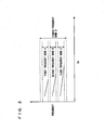
- a frequency near the frequency shown by the solid line in Fig. 2 is generated in engine 100.
- the frequency of vibration generated due to the knocking is not constant but varies in a certain frequency band. Therefore, in the embodiment, as shown in Fig. 2 , the vibration in a fourth frequency band D including a first frequency band A, a second frequency band B and a third frequency band C is detected.
- CA represents the crank angle.
- the number of frequency bands of vibration generated due to the knocking is not restricted to three.
- Engine ECU 200 includes an A/D (analog/digital) converter 400, a band-pass filter 410 and an integrating portion 420.
- A/D analog/digital
- A/D converter 400 converts an analog signal sent from knock sensor 300 into a digital signal.
- Band-pass filter 410 allows passage of only signals in the fourth frequency band D out of signals sent from knock sensor 300. In other words, band-pass filter 410 extracts only the vibration in the fourth frequency band D from the vibration detected by knock sensor 300.
- Integrating portion 420 integrates signals selected by band-pass filter 410, i.e., magnitudes of vibration in a range of crank angle of 5° at a time.
- the resultant value determined by this integration is hereinafter referred to as integrated value.
- integrated value By calculating the integrated value in association with the crank angle, a vibration waveform of engine 100 is detected as shown in Fig. 4 .
- the detected vibration waveform is compared with a knock waveform model stored in ROM 202 of engine ECU 200 as shown in Fig. 5 .
- the knock waveform model is formed in advance as a model of the vibration waveform in the case where knocking occurs in engine 100.
- the magnitudes of vibration are expressed as dimensionless numbers in a range of 0 to 1 and the magnitude of vibration is not uniquely associated with the crank angle.
- the magnitude of vibration is defined as the one that decreases as the crank angle increases after a peak value of the magnitude of vibration, a specific crank angle at which the magnitude of vibration has the peak value is not defined.
- the knock waveform model in the embodiment corresponds to vibration in a predetermined range of crank angle after the magnitude of vibration caused by knocking reaches the peak value.
- a knock waveform model may be stored that corresponds to the vibration after the rising edge of vibration caused by knocking.
- the knock waveform model is formed and stored in advance based on a vibration waveform of engine 100 detected when knocking is forcibly generated experimentally.
- the knock waveform model is formed by using engine 100 with dimensions of engine 100 and an output value of knock sensor 300 which are median values of dimensional tolerance and tolerance of the output value of knock sensor 300 (hereafter referred to as "median characteristic engine”).
- the knock waveform model is a vibration waveform in the case where the knocking is forcibly generated in the median characteristic engine.
- the method of forming the knock waveform model is not limited to this, and the model may alternatively be formed by simulation.
- the normalization means to express the magnitude of vibration as a dimensionless number in a range of 0 to 1 by dividing, for example, each integrated value by the maximum integrated value of the detected vibration waveform.
- the method of normalization is not limited to this.
- engine ECU 200 calculates a correlation coefficient K which represents the degree of similarity of the normalized vibration waveform to the knock waveform model (represents a deviation of the vibration waveform and the knock waveform model from each other).
- the absolute value of the difference (deviation amount) between the magnitude in the normalized vibration waveform and the magnitude in the knock waveform model is calculated for each crank angle (every 5° of the crank angle) to thereby calculate correlation coefficient K.
- the absolute value of the difference between the magnitude in the vibration waveform and the magnitude in the knock waveform model may alternatively be calculated for every crank angle other than 5°.
- the minimum value of the magnitude in the vibration waveform in the range of crank angle for which the difference between the magnitude in the vibration waveform and the magnitude in the knock waveform model is calculated is used.
- the minimum value of the magnitude in the detected vibration waveform namely the minimum value of the magnitude in the knock detection gate
- any value other than the minimum value of the magnitude in the vibration waveform may be used.
- the method of calculating correlation coefficient K is not limited to this.
- BGL is determined in advance by simulation or experiment for example and stored in ROM 202. The method of calculating knock magnitude N is not limited to this.
- engine ECU 200 compares calculated knock magnitude N and a determination value V(KX) stored in ROM 202 with each other, and further compares the detected waveform and the stored knock waveform model with each other. Then, engine ECU 200 determines, for each ignition cycle, whether or not knocking has occurred in engine 100.
- determination values V(KX) are stored as a map for respective ranges divided according to an operation state represented by the parameters that are engine speed NE and intake air amount KL.
- nine ranges for each cylinder are provided, which are divided as follows: low speed (NE ⁇ NE(1)); medium speed (NE(1) ⁇ NE ⁇ NE(2)); high speed (NE(2) ⁇ NE); low load (KL ⁇ KL(1)); medium load (KL(1) ⁇ KL ⁇ KL(2)); and high load (KL(2) ⁇ KL).
- the number of the ranges is not limited to this.
- the ranges may alternatively be divided using parameters other than engine speed NE and intake air amount KL.
- step 100 (hereafter “step” will be abbreviated as "S"), engine ECU 200 detects engine speed NE based on a signal sent from crank position sensor 306 and detects intake air amount KL based on a signal sent from air flow meter 314.
- engine ECU 200 detects the magnitude of vibration of engine 100 based on a signal sent from knock sensor 300.
- the magnitude of vibration is expressed as an output voltage value of knock sensor 300.
- the magnitude of vibration may be expressed as a value corresponding to the output voltage value of knock sensor 300.
- the magnitude is detected in the range from the top dead center to 90° (90° in crank angle) in a combustion stroke.
- engine ECU 200 calculates a value (integrated value) by integrating the output voltage values (values representing respective magnitudes of vibration) of knock sensor 300 for every 5° (for 5°) in crank angle. By calculating the integrated values, a vibration waveform of engine 100 is detected.
- engine ECU 200 determines the largest integrated value (peak value P) among integrated values in the vibration waveform of engine 100.
- engine ECU 200 normalizes the vibration waveform of engine 100.
- the normalization means to express the magnitude of vibration as a dimensionless number in a range of 0 to 1 by dividing, for example, each integrated value by the calculated peak value.
- engine ECU 200 matches the crank angle corresponding to peak value P with the timing (crank angle) corresponding to the maximum magnitude of vibration in the knock waveform model, and calculates correlation coefficient K.
- engine ECU 200 calculates knock magnitude N by dividing peak value P by BGL.
- engine ECU 200 determines whether correlation coefficient K is larger than a threshold value K(0) and knock magnitude N is larger than determination value V(KX) When correlation coefficient K is larger than threshold value K(0) and knock magnitude N is larger than determination value V(KX) (YES in S114), the process proceeds to S116. Otherwise (NO in S114), the process proceeds to S120.
- engine ECU 200 determines that knocking has occurred. In S118, engine ECU 200 retards the ignition timing.
- engine ECU 200 determines that knocking has not occurred. In S122, engine ECU 200 advances the ignition timing.
- engine ECU 200 that is the knocking determination device according the embodiment, based on the above-described configuration and flowchart.
- engine speed NE is detected based on the signal sent from crank position sensor 306 and intake air amount KL is detected based on the signal sent from air flow meter 314 (S100). Moreover, based on the signal sent from knock sensor 300, the magnitude of vibration of engine 100 is detected (S102).
- the vibration waveform of which delicate magnitude variations are suppressed can be detected. Therefore, it is easy to compare the detected vibration waveform and the knock waveform model with each other.
- peak value P of the integrated values in the vibration waveform of engine 100 is determined (S106).
- the integrated value in the vibration waveform of engine 100 is divided by the determined peak value P to normalize the vibration waveform (S108).
- the magnitude of vibration in the vibration waveform is represented by a dimensionless number in a range of 0 to 1.
- the vibration waveform and the knock waveform model can be compared with each other. Therefore, it is unnecessary to store many knock waveform models associated with magnitudes of vibration, and accordingly the knock waveform model can be prepared easily.
- the degree of similarity between the detected vibration waveform and the knock waveform model can be expressed numerically and accordingly determined objectively. Further, by comparing the vibration waveform with the knock waveform model, whether or not vibration is caused by knocking can be analyzed based on the behavior of the vibration such as damping tendency of the vibration.
- knock magnitude N is calculated (S112). Accordingly, based on the magnitude of vibration, it can be analyzed in more detail whether or not the vibration of engine 100 is caused by knocking.
- the engine ECU which is the knocking determination device in the embodiment determines whether or not knocking has occurred, based on the value determined by dividing ⁇ S(I), which is the sum of absolute values ⁇ S(I) of respective differences each between the magnitude in the vibration waveform and the magnitude in the knock waveform model for each crank angle, by area S of the knock waveform model corresponding to magnitudes equal to and larger than the reference value.
- ⁇ S(I) which is the sum of absolute values ⁇ S(I) of respective differences each between the magnitude in the vibration waveform and the magnitude in the knock waveform model for each crank angle
- area S of the knock waveform model corresponding to magnitudes equal to and larger than the reference value.
- the present embodiment differs from the first embodiment in that correlation coefficient K is calculated without using area S of the knock waveform model.
- the second embodiment is identical to the first embodiment. Respective functions are also identical to each other. Therefore, the detailed description thereof will not be repeated here.
- Allowable value D is an allowable value representing an allowable ⁇ S(I). Allowable value D is determined by subtracting a positive reference value from the maximum value of the magnitude in the vibration waveform and dividing the resultant value by a predetermined coefficient ("3" for example). As the reference value used for calculating allowable value D, the minimum value of the magnitude in the vibration waveform is used as shown in Fig. 10 . As long as the reference value is a positive value, any value other than the minimum magnitude in the vibration waveform may be used. Alternatively, allowable value D may be calculated by dividing, by a predetermined coefficient, a difference between any value other than the maximum value of the magnitude in the vibration waveform and a reference value. The method of calculating correlation coefficient K is not limited to this.
- the coefficient used for calculating allowable value D is changed according to the speed of engine 100. For example, as the speed of engine 100 is higher, the coefficient is made larger. Thus, as the speed of engine 100 is higher, allowable value D can be made smaller.
- ⁇ ( ⁇ S(I) / D) is the sum of values each determined by dividing ⁇ S(I) by allowable value D.
- correlation coefficient K is larger then threshold value K(0) is identical to the fact that ⁇ S(I) / D is smaller than N ⁇ (1 - K(0)).
- the engine ECU which is the knock determination device in the present embodiment determines whether knocking has occurred or not, based on the value determined by dividing, by allowable value D, ⁇ S(I) which is the sum of absolute values ⁇ S(I) of respective differences each between the magnitude in the vibration waveform and the magnitude in the knock waveform model for each crank angle. Allowable value D is calculated by subtracting a reference value from the maximum value in the vibration waveform and dividing the resultant difference by a coefficient. In this way as well, similar effects to those of the first embodiment can be achieved. Moreover, since area S of the knock waveform model is not used, a larger influence of the difference between the vibration waveform and the knock waveform model can be reflected in correlation coefficient K. Accordingly, in the case where the difference between the magnitude in the vibration waveform and the magnitude in the knock waveform model is small while knocking does not occur, occurrence of erroneous determination that knocking has occurred can be reduced.
- the present embodiment differs from the second embodiment in that a smoothing method called exponential smoothing is used to smooth respective minimum magnitudes in vibration waveforms detected in a plurality of ignition cycles and thereby set the reference value.
- a smoothing method called exponential smoothing is used to smooth respective minimum magnitudes in vibration waveforms detected in a plurality of ignition cycles and thereby set the reference value.
- the third embodiment is identical to the second embodiment. Therefore, the detailed description thereof will not be repeated here.
- the reference value is calculated (set) by using equation (7) or equation (8) indicated below to smooth the minimum values of magnitude in respective vibration waveforms detected previously in a plurality of ignition cycles.
- RV(i) represents a reference value that is calculated in the latest ignition cycle
- RV(i-1) represents a reference value that is calculated in the preceding ignition cycle
- MIN(i-1) represents the minimum value of magnitude in the vibration waveform detected in the preceding ignition cycle
- X and Y (Y > X) are coefficients.
- RV i RV ⁇ i - 1 + X ⁇ MIN ⁇ i - 1 - RV ⁇ i - 1
- RV i RV ⁇ i - 1 + Y ⁇ MIN ⁇ i - 1 - RV ⁇ i - 1
- equation (7) is used to set the reference value.
- equation (8) is used to set the reference value.
- the reference value is set by performing the smoothing to provide a smaller influence of the minimum value of magnitude in the vibration waveform detected in the latter ignition cycle as compared with the case where the minimum value in the latter ignition cycle is smaller than that detected in the former ignition cycle.
- the reference value can be set to the one that changes gradually.
- the reference value can be set to the one that is unlikely to be large. Therefore, even if large mechanical vibration occurs due to, for example, high engine speed NE, the reference value can be prevented from becoming excessively large.
- the smoothing method is not limited to the above-described one.
- the minimum values of magnitude may be smoothed using the simple moving average or low-pass filter or the like.
- the present embodiment differs from the first embodiment in that the detected vibration waveform is not normalized and that the maximum value of magnitude in the knock waveform model is set based on the maximum value of magnitude in the detected vibration waveform.
- the fourth embodiment is identical to the first embodiment. Therefore, the detailed description thereof will not be repeated here.
- vibration at a specific frequency occurs in engine 100. If the vibration is detected in a relatively broader frequency band, it is more likely that the detected vibration includes noise (for example, vibration caused by an in-cylinder injector or intake/exhaust valve sitting on its seat) other than vibration caused by knocking.
- noise for example, vibration caused by an in-cylinder injector or intake/exhaust valve sitting on its seat
- any noise component included in the magnitude of the detected vibration can be suppressed while a characteristic component (such as the timing of occurrence of vibration and damping rate thereof) is removed from the vibration waveform.
- a characteristic component such as the timing of occurrence of vibration and damping rate thereof
- vibration is detected in a first frequency band A, a second frequency band B and a third frequency band C that are set to have a smaller bandwidth, in order to precisely capture vibration specific to knocking.
- the vibration is detected in a broader fourth frequency band D including the first to third frequency bands A to C so as to capture the noise.
- engine ECU 200 includes, in addition to A/D converter 400, a band-pass filter (1) 431, a band-pass filter (2) 432, a band-pass filter (3) 433, a band-pass filter (4) 434, and an integrating portion 435.
- Band-pass filter (1) 431 passes only the signals in first frequency band A out of signals transmitted from knock sensor 300. In other words, band-pass filter (1) 431 extracts only the vibration in first frequency band A out of vibration detected by knock sensor 300.
- Band-pass filter (2) 432 passes only the signals in second frequency band B out of signals transmitted from knock sensor 300. In other words, band-pass filter (2) 432 extracts only the vibration in second frequency band B out of vibration detected by knock sensor 300.
- Band-pass filter (3) 433 passes only the signals in third frequency band C out of signals transmitted from knock sensor 300. In other words, band-pass filter (3) 433 extracts only the vibration in third frequency band C out of vibration detected by knock sensor 300.
- Band-pass filter (4) 434 passes only the signals in fourth frequency band D out of signals transmitted from knock sensor 300. In other words, band-pass filter (4) 434 extracts only the vibration in fourth frequency band D out of vibration detected by knock sensor 300.
- Integrating portion 435 calculates the integrated value by integrating the signals selected by band-pass filters (1) 431 to (4) 434, namely integrating the magnitudes of vibration in a range of crank angle of 5° at a time. The integrated value is calculated for each frequency band.
- respective integrated values calculated for first to third frequency bands A to C are added together in association with the crank angle.
- respective vibration waveforms of first to third frequency bands A to C are synthesized.
- the synthesized waveform of first to third frequency bands A to C and the vibration waveform of fourth frequency band D are used as vibration waveforms of engine 100.
- the vibration waveform (integrated value) of forth frequency band D is not synthesized but used singly.
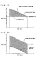
- the vibration waveform of fourth frequency band D is not normalized but compared with the knock waveform model as shown in Fig. 12 .
- the magnitude in the knock waveform model is determined based on the magnitude (integrated value) in the vibration waveform of fourth frequency band D. More specifically, the maximum value of magnitude in the knock waveform model is determined based on the maximum value of magnitude in the vibration waveform of fourth frequency band D.
- the damping rate after the maximum value, namely the shape of the knock waveform model, is predetermined. The method of setting the maximum value of magnitude in the knock waveform model will be described hereinlater.
- area S of the knock waveform model is, as shown in Fig. 13 , determined by integrating the magnitude of vibration in the knock waveform model by the crank angle (the sum of magnitudes of vibration in the knock waveform model).
- An equation used for calculating correlation coefficient K is the same as that of the first embodiment.
- engine ECU 200 calculates knock magnitude N representing the magnitude of vibration. Namely, the maximum value of the integrated values in the synthesized waveform of first to third frequency bands A to C is divided by BGL to calculate knock magnitude N.
- the maximum value of the integrated values in the synthesized waveform of first to third frequency bands A to C is used to correct determination value V(KX) to be compared with knock magnitude N.
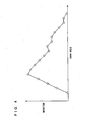
- knock determination level V(KD) is calculated based on a frequency distribution as shown in Fig. 14 representing the relation between a magnitude value LOG(V), which is determined by logarithmically converting the maximum,value of the integrated values in the synthesized waveform of first to third frequency bands A to C, and the frequency (number of times, also called probability) at which each magnitude value LOG(V) is detected.
- Magnitude value LOG(V) is calculated for each range for which engine speed NE and intake air amount KL are used as parameters. Based on calculated magnitude value LOG(V), median value V(50) at which the accumulative sum of frequencies of magnitudes LOG(V) from the minimum value reaches 50% is calculated. Furthermore, a standard deviation ⁇ of magnitude values LOG(V) equal to or smaller than median value V(50) is calculated. In the present embodiment, a median value V(50) and a standard deviation ⁇ , which approximate the median value and standard deviation calculated based on a plurality of magnitude values LOG(V) (e.g., 200 cycles), are calculated for each ignition cycle by the following calculation method.
- a predetermined value C(1) is added to the preceding calculated median value V(50) and the resultant value is determined as the latest median value V(50).
- a predetermined value C(2) e.g., C(2) and C(1) are the same value is subtracted from the preceding calculated median value V(50) to determine the resultant value as the latest median value V(50):
- the method of calculating knock determination level V(KD) is not limited to this.
- the proportion or ratio (frequency) of magnitude values LOG(V) greater than knock determination level V(KD) is determined as a frequency of occurrence of knocking, namely the number of magnitude values LOG(V) greater than knock determination level V(KD) is counted to determine knock proportion KC. If knock proportion KC is greater than a threshold value KC(0), then determination value V(KX) is corrected to be reduced by a predetermined correction amount so that the frequency of retarding ignition timing is higher. If knock proportion KC is smaller than threshold value KC(0), then determination value V(KX) is corrected to be increased by a predetermined correction amount so that the frequency of advancing ignition timing is higher.
- the maximum value of magnitude in the knock waveform model is set by generating a distribution of frequency of respective maximum values of magnitude in vibration waveforms of fourth frequency band D detected in a plurality of ignition cycles.
- a frequency distribution is generated for a value determined by logarithmically converting the maximum value of magnitude in the vibration waveform of fourth frequency band D as shown in Fig. 15 .
- the product of coefficient U(2) (U(2) ⁇ U(1)) and standard deviation ⁇ is added to the median value.
- the resultant sum is inverse logarithmically converted, and the maximum value of magnitude in the knock waveform model is set to the resultant value.
- the program described below is repeated in predetermined cycles. Further, the same process steps as those of the first embodiment are denoted by the same step number. Therefore, the detailed description thereof will not be repeated here.
- engine ECU 200 calculates the integrated value by integrating output voltage values of knock sensor 300 for a range of crank angle of 5° at time for the vibration in each of first to fourth frequency bands A to D.
- respective integrated values of first to third frequency bands A to C are added together in association with the crank angle. Namely respective vibration waveforms of first to third frequency bands A to C are synthesized.
- engine ECU 200 updates the frequency distribution used for setting the maximum value of magnitude in the knock waveform model, using the maximum value of magnitude (integrated value) in the vibration waveform of fourth frequency band D detected in the latest ignition cycle.
- engine ECU 200 sets the maximum value of magnitude in the knock waveform model.
- engine ECU 200 calculates correlation coefficient K by comparing the knock waveform model and the vibration waveform of fourth frequency band D with each other. In S408, engine ECU 200 calculates knock magnitude N by dividing the maximum value of the integrated values of the synthesized waveform of first to third frequency bands A to C by BGL.
- engine ECU 200 which is the knock determination device of the present embodiment, based on the above-described configuration and flowchart.
- an integrated value for every 5° is calculated for each vibration of first to fourth frequency bands A to D (S400). Further, respective calculated integrated values of first to third frequency bands A to C are added together in association with the crank angle to synthesize the vibration waveforms.
- the synthesized waveform of first to third frequency bands as well as the vibration waveform of fourth frequency band D are detected.
- the vibration waveform of fourth frequency band D is compared with the knock waveform model to calculate correlation coefficient K, and the coefficient is used when it is determined in each ignition cycle whether or not knocking has occurred.
- the frequency distribution is updated that is used for setting the maximum value of magnitude in the knock waveform model, using the maximum value of the integrated values in the vibration waveform of fourth frequency band D detected in the latest ignition cycle (S402). Using the frequency distribution, the maximum value of magnitude in the knock waveform model is set (S404).
- any value that is regarded as the one due to knocking can be set as the maximum value of the magnitude in the knock waveform model. Therefore, if the maximum value of magnitude in the vibration waveform of fourth frequency band D is small, a larger difference can be provided between the magnitude in the knock waveform model and the magnitude in the vibration waveform.
- Correlation coefficient K is calculated by comparing this knock waveform model and the vibration waveform of fourth frequency band D with each other (S406). Further, knock magnitude N is calculated by dividing, by BGL, the maximum value of the integrated values in the synthesized waveform of first to third frequency bands A to C (S408). Using these correlation coefficient K and knock magnitude N, whether or not knocking has occurred is determined.
- the engine ECU which is the knock determination device of the present embodiment uses the magnitude in the detected vibration waveform to set the magnitude in the knock waveform model.
- Correlation coefficient K is calculated based on the value determined by dividing, by area S of the knock waveform model, ⁇ S(I) which is the sum of differences ⁇ S(I) each between the magnitude in the detected vibration waveform and the magnitude in the knock waveform model.
- This correlation coefficient K is used to determine whether or not knocking has occurred.
- correlation coefficient K that can clearly reflect the difference between the magnitude in the detected vibration waveform and the magnitude in the knock waveform model can be used to determine whether knocking has occurred or not. Accordingly, in the case where knocking has not occurred, it can be correctly determined that knocking has not occurred.
- the present embodiment differs from the first embodiment in that the vibration waveform and the knock waveform model are compared with each other in a comparison segment that is determined according to the operating state of engine 100.
- the method of calculating correlation coefficient K in the present embodiment also differs from the method of calculating correlation coefficient K in the first embodiment.
- the present embodiment and the first embodiment are identical to each other. Therefore, the detailed description thereof will not be repeated here.
- equation (1) used for calculating the correlation coefficient the sum of ⁇ S(I) in the comparison segment is used as ⁇ S(I). Further, as area S of the knock waveform model, the value determined by integrating (summing) the magnitudes in the comparison segment of the knock waveform model is used.
- the crank angle at which the magnitude (integrated value) of the detected vibration waveform has the peak value P and the timing at which the magnitude of vibration has the maximum value in the knock waveform model are matched each other, and correlation coefficient K is calculated.
- the comparison segment is set, for example, according to a map using engine speed NE and load as parameters.
- engine speed NE is smaller than a threshold value
- a range of crank angle of 0 to 20° is set as the comparison segment.
- the comparison segment is set to a more advanced range of crank angle.
- the comparison segment may be set according to any one of engine speed NE and the load. The method of setting the comparison segment is not limited to this.
- the program described below is repeatedly executed in predetermined cycles.
- the same process step as that of the first embodiment is denoted by the same step number. Therefore, the detailed description thereof will not be repeated here.
- engine ECU 200 calculates the load of engine 100 based on engine speed NE and intake air amount KL.
- the method of calculating the load of engine 100 may be any general well-known technique. Therefore, the detailed description thereof will not be repeated here.
- engine ECU 200 sets the comparison segment for comparing the knock waveform model and the vibration waveform with each other, according to engine speed NE and the load.
- the comparison segment can be set in which the difference is clearly seen between the waveform due to knocking and the noise (vibration caused when the in-cylinder injector or intake/exhaust valve sits on its seat) other than vibration caused by knocking.
- the present embodiment differs form the first embodiment in that a vibration waveform obtained by subtracting a reference value from the magnitude in the detected vibration waveform is compared with the knock waveform model.
- the present embodiment is identical to the first embodiment. Therefore, the detailed description thereof will not be repeated here.
- a reference value is subtracted from the magnitude in the normalized vibration waveform to obtain a vibration waveform to be used that is determined by removing the portion less than the reference value from the normalized vibration waveform only.
- ⁇ S(I) is calculated by adding together absolute values ⁇ S(I) that are each the difference between the magnitude in the knock waveform model and the magnitude in the vibration waveform whose magnitude is reduced by the reference value.
- area S of the knock waveform model is determined by integrating (adding together) the magnitudes in the knock waveform model.
- the reference value to be used is the minimum value of magnitude in the vibration waveform in a range of crank angle in which the difference between the magnitude in the vibration waveform and the magnitude in the knock waveform model is calculated.
- the minimum value of magnitude in the detected vibration waveform namely the minimum value of magnitude in the knock detection gate may be used as the reference value.
- any value other than the minimum value of magnitude in the vibration waveform may be used.
- the difference between the magnitude in the vibration waveform and the magnitude in the knock waveform model can be increased by the reference value.
- the detected vibration waveform is similar to that of the knock waveform model, it can appropriately be determined that knocking has occurred if respective magnitudes are different from each other. Accordingly, erroneous determination can be reduced that is the determination that knocking has occurred regardless of the fact that knocking has not occurred.
Landscapes
- Engineering & Computer Science (AREA)
- Chemical & Material Sciences (AREA)
- Combustion & Propulsion (AREA)
- Physics & Mathematics (AREA)
- General Physics & Mathematics (AREA)
- Mechanical Engineering (AREA)
- General Engineering & Computer Science (AREA)
- Combined Controls Of Internal Combustion Engines (AREA)
Abstract
Claims (15)
- Dispositif de détermination de cognement d'un moteur à combustion interne, comprenant :un capteur (306) de position de vilebrequin détectant un angle de vilebrequin dudit moteur à combustion interne (100) ;un capteur de détonation (300) détectant une grandeur de vibration dudit moteur à combustion interne (100) en même temps que l'angle de vilebrequin ; etune unité d'exploitation (200), oùladite unité d'exploitation (200) détecte une forme d'onde de vibration dans un intervalle prédéterminé d'angle de vilebrequin, sur la base de la grandeur de vibration dudit moteur à combustion interne (100),ladite unité d'exploitation (200) calcule une première valeur sur la base d'une différence entre une grandeur dans ladite forme d'onde détectée et une grandeur dans un modèle de forme d'onde qui est prédéterminé comme étant une référence de la forme d'onde de vibration dudit moteur à combustion interne (100), caractérisé en ce queladite unité d'exploitation (200) calcule une deuxième valeur sur la base de l'une parmi une valeur déterminée en soustrayant une valeur de référence positive de la grandeur dans ledit modèle de forme d'onde et une valeur déterminée en soustrayant ladite valeur de référence de la grandeur dans ladite forme d'onde détectée,ladite unité d'exploitation (200) calcule une troisième valeur sur la base de ladite première valeur et de ladite deuxième valeur, etladite unité d'exploitation (200) détermine si un cognement a eu lieu ou non dans ledit moteur à combustion interne (100) sur la base de ladite troisième valeur.
- Dispositif selon la revendication 1, dans lequel
ladite unité d'exploitation (200) calcule ladite première valeur qui est plus petite à mesure que la différence entre la grandeur dans ladite forme d'onde détectée et la grandeur dans ledit modèle de forme d'onde est plus petite,
ladite unité d'exploitation (200) calcule ladite deuxième valeur qui est plus petite à mesure que l'une parmi la valeur déterminée en soustrayant ladite valeur de référence de la grandeur dans ledit modèle de forme d'onde et la valeur déterminée en soustrayant ladite valeur de référence de la grandeur dans ladite forme d'onde détectée est plus petite,
ladite unité d'exploitation (200) calcule ladite troisième valeur qui est plus petite à mesure que ladite première valeur est plus petite et qui est plus grande à mesure que ladite deuxième valeur est plus petite, et
ladite unité d'exploitation (200) détermine qu'un cognement a eu lieu dans ledit moteur à combustion interne (100) lorsque ladite troisième valeur est inférieure à une valeur prédéterminée. - Dispositif selon la revendication 2, dans lequel ladite unité d'exploitation (200) calcule ladite première valeur en additionnant des différences qui sont chacune une différence entre une grandeur dans ladite forme d'onde détectée et une grandeur dans ledit modèle de forme d'onde pour chaque angle de vilebrequin prédéterminé.
- Dispositif selon la revendication 2, dans lequel ladite deuxième valeur calculée par ladite unité d'exploitation (200) est l'une parmi une valeur déterminée en additionnant une pluralité de valeurs qui sont obtenues chacune en soustrayant ladite valeur de référence d'une grandeur dans ledit modèle de forme d'onde pour chaque angle de vilebrequin prédéterminé, et une valeur déterminée en divisant, par un coefficient, une valeur obtenue en soustrayant ladite valeur de référence d'une valeur maximale de grandeur dans ladite forme d'onde détectée.
- Dispositif selon la revendication 2, dans lequel
ladite unité d'exploitation (200) calcule ladite troisième valeur en divisant ladite première valeur par ladite deuxième valeur. - Dispositif selon la revendication 1, dans lequel ladite valeur de référence est une valeur minimale de grandeur dans ladite forme d'onde détectée dans une gamme d'angle de vilebrequin pour laquelle la différence entre la grandeur dans ladite forme d'onde détectée et la grandeur dans ledit modèle de forme d'onde est calculée.
- Dispositif de détermination de cognement d'un moteur à combustion interne, comprenant :un capteur (306) de position de vilebrequin détectant un angle de vilebrequin dudit moteur à combustion interne (100) ;un capteur de détonation (300) détectant une grandeur de vibration dudit moteur à combustion interne (100) en même temps que l'angle de vilebrequin ; etune unité d'exploitation (200), oùladite unité d'exploitation (200) détecte une forme d'onde de vibration dans un intervalle prédéterminé d'angle de vilebrequin, sur la base de la grandeur de vibration dudit moteur à combustion interne (100),ladite unité d'exploitation (200) calcule une première valeur sur la base d'une différence entre une grandeur dans ladite forme d'onde détectée et une grandeur dans un modèle de forme d'onde qui est une référence de la forme d'onde de vibration dudit moteur à combustion interne (100), caractérisé ce queladite unité d'exploitation (200) règle une grandeur dans ledit modèle de forme d'onde sur la base des grandeurs respectives dans des formes d'onde respectives détectées dans une pluralité de cycles d'allumage,ladite unité d'exploitation (200) calcule une deuxième valeur sur la base de la grandeur dans ledit modèle de forme d'onde,ladite unité d'exploitation (200) calcule une troisième valeur sur la base de ladite première valeur et de ladite deuxième valeur, etladite unité d'exploitation (200) détermine si un cognement a eu lieu ou non dans ledit moteur à combustion interne (100) sur la base de ladite troisième valeur.
- Dispositif selon la revendication 7, dans lequel ladite unité d'exploitation (200) règle une valeur maximale de grandeur dans ledit modèle de forme d'onde, sur la base des valeurs maximales respectives de grandeur dans des formes d'onde respectives détectées dans ladite pluralité de cycles d'allumage.
- Dispositif selon la revendication 7, dans lequel ladite unité d'exploitation (200) calcule ladite première valeur en additionnant des différences qui sont chacune une différence entre une grandeur dans ladite forme d'onde détectée et une grandeur dans ledit modèle de forme d'onde,
ladite unité d'exploitation (200) calcule ladite deuxième valeur en additionnant des grandeurs dans ledit modèle de forme d'onde,
ladite unité d'exploitation (200) calcule ladite troisième valeur en divisant ladite première valeur par ladite deuxième valeur, et
ladite unité d'exploitation (200) détermine qu'un cognement a eu lieu dans ledit moteur à combustion interne (100) lorsque ladite troisième valeur est inférieure à une valeur prédéterminée. - Dispositif de détermination de cognement d'un moteur à combustion interne, comprenant :un capteur (306) de position de vilebrequin détectant un angle de vilebrequin dudit moteur à combustion interne (100) ;un capteur de détonation (300) détectant une grandeur de vibration dudit moteur à combustion interne (100) en même temps que l'angle de vilebrequin ; etune unité d'exploitation (200),ladite unité d'exploitation (200) détecte une forme d'onde de vibration dans un premier intervalle d'angle de vilebrequin, sur la base de la grandeur de vibration dudit moteur à combustion interne (100),ladite unité d'exploitation (200) calcule une première valeur sur la base d'une différence entre une grandeur dans ladite forme d'onde détectée et une grandeur dans un modèle de forme d'onde qui est prédéterminé comme étant une référence de la forme d'onde de vibration dudit moteur à combustion interne (100), caractérisé en celadite unité d'exploitation (200) règle un deuxième intervalle d'angle de vilebrequin en fonction d'un état de fonctionnement dudit moteur à combustion interne (100), et calcule la première valeur dans ledit deuxième intervalle,ladite unité d'exploitation (200) calcule une deuxième valeur sur la base de la grandeur dans ledit modèle de forme d'onde dans ledit deuxième intervalle,ladite unité d'exploitation (200) calcule une troisième valeur sur la base de ladite première valeur et de ladite deuxième valeur, etladite unité d'exploitation (200) détermine si un cognement a eu lieu ou non dans ledit moteur à combustion interne (100) sur la base de ladite troisième valeur.
- Dispositif de détermination de cognement d'un moteur à combustion interne, comprenant :un capteur (306) de position de vilebrequin détectant un angle de vilebrequin dudit moteur à combustion interne (100) ;un capteur de détonation (300) détectant une grandeur de vibration dudit moteur à combustion interne (100) en même temps que l'angle de vilebrequin ; etune unité d'exploitation (200), oùladite unité d'exploitation (200) détecte une forme d'onde de vibration dans un intervalle prédéterminé d'angle de vilebrequin, sur la base de la grandeur de vibration dudit moteur à combustion interne (100),ladite unité d'exploitation (200) calcule une première valeur sur la base d'une différence entre une grandeur dans ladite forme d'onde détectée et une grandeur dans un modèle de forme d'onde qui est prédéterminé comme étant une référence de la forme d'onde de vibration dudit moteur à combustion interne (100), caractérisé en ce queladite unité d'exploitation (200) détecte la forme d'onde de vibration dans l'intervalle prédéterminé d'angle de vilebrequin, sur la base d'une grandeur obtenue en soustrayant une valeur de référence positive de la grandeur de vibration dudit moteur à combustion interne (100),ladite unité d'exploitation (200) calcule une deuxième valeur sur la base de la grandeur dans ledit modèle de forme d'onde,ladite unité d'exploitation (200) calcule une troisième valeur sur la base de ladite première valeur et de ladite deuxième valeur, etladite unité d'exploitation (200) détermine si un cognement a eu lieu ou non dans ledit moteur à combustion interne (100) sur la base de ladite troisième valeur.
- Procédé de détermination de cognement d'un moteur à combustion interne, comprenant les étapes qui consistent:à détecter un angle de vilebrequin dudit moteur combustion interne (100) ;à détecter une grandeur de vibration dudit moteur à combustion interne (100) en même temps que l'angle de vilebrequin ;à détecter une forme d'onde de vibration dans un intervalle prédéterminé d'angle de vilebrequin, sur la base de la grandeur de vibration dudit moteur à combustion interne (100) ;à calculer une première valeur sur la base d'une différence entre une grandeur dans ladite forme d'onde détectée et une grandeur dans un modèle de forme d'onde qui est prédéterminé comme étant une référence de la forme d'onde de vibration dudit moteur à combustion interne (100)
; caractérisé par le faitde calculer une deuxième valeur sur la base de l'une parmi une valeur déterminée en soustrayant une valeur de référence positive de la grandeur dans ledit modèle de forme d'onde et une valeur déterminée en soustrayant ladite valeur de référence de la grandeur dans ladite forme d'onde détectée ;de calculer une troisième valeur sur la base de ladite première valeur et de ladite deuxième valeur, etde déterminer si un cognement a eu lieu ou non dans ledit moteur à combustion interne (100) sur la base de ladite troisième valeur. - Procédé de détermination de cognement d'un moteur à combustion interne, comprenant les étapes qui consistent:à détecter un angle de vilebrequin dudit moteur à combustion interne (100) ;à détecter une grandeur de vibration dudit moteur à combustion interne (100) en même temps que l'angle de vilebrequin ;à détecter une forme d'onde de vibration dans un intervalle prédéterminé d'angle de vilebrequin, sur la base de la grandeur de vibration dudit moteur à combustion interne (100) ;à calculer une première valeur sur la base d'une différence entre une grandeur dans ladite forme d'onde détectée et une grandeur dans un modèle de forme d'onde qui est une référence de la forme d'onde de vibration dudit moteur à combustion interne (100) ; caractérisé par le faitde régler une grandeur dans ledit modèle de forme d'onde sur la base des grandeurs respectives dans des formes d'onde respectives détectées dans une pluralité de cycles d'allumage ;de calculer une deuxième valeur sur la base de la grandeur dans ledit modèle de forme d'onde ;de calculer une troisième valeur sur la base de ladite première valeur et de ladite deuxième valeur ; etde déterminer si un cognement a eu lieu ou non dans ledit moteur à combustion interne (100) sur la base de ladite troisième valeur.
- Procédé selon la revendication 13, dans lequel ladite étape qui consiste à calculer ladite première valeur comporte l'étape qui consiste à calculer ladite première valeur en additionnant des différences qui sont chacune une différence entre une grandeur dans ladite forme d'onde détectée et une grandeur dans ledit modèle de forme d'onde,
ladite étape qui consiste à calculer ladite deuxième valeur comporte l'étape qui consiste à calculer ladite deuxième valeur en additionnant des grandeurs dans ledit modèle de forme d'onde,
ladite étape qui consiste à calculer ladite troisième valeur comporte l'étape qui consiste à calculer ladite troisième valeur en divisant ladite première valeur par ladite deuxième valeur, et
ladite étape qui consiste à déterminer si un cognement a eu lieu ou non comporte l'étape qui consiste à déterminer qu'un cognement a eu lieu dans ledit moteur à combustion interne (100) lorsque ladite troisième valeur est inférieure à une valeur prédéterminée. - Procédé de détermination de cognement d'un moteur à combustion interne, comprenant les étapes qui consistent:à détecter un angle de vilebrequin dudit moteur à combustion interne (100) ;à détecter une grandeur de vibration dudit moteur à combustion interne (100) en même temps que l'angle de vilebrequin ;à détecter une forme d'onde de vibration dans un premier intervalle d'angle de vilebrequin, sur la base de la grandeur de vibration dudit moteur à combustion interne (100) ;à régler un deuxième intervalle d'angle de vilebrequin en fonction d'un état de fonctionnement dudit moteur à combustion interne (100) ;à calculer une première valeur sur la base d'une différence, dans ledit deuxième intervalle, entre une grandeur dans ladite forme d'onde détectée et une grandeur dans un modèle de forme d'onde qui est prédéterminé comme étant une référence de la forme d'onde de vibration dudit moteur à combustion interne (100) ; caractérisé par le faitde calculer une deuxième valeur sur la base de la grandeur dans ledit modèle de forme d'onde dans ledit deuxième intervalle ;de calculer une troisième valeur sur la base de ladite première valeur et de ladite deuxième valeur ; etde déterminer si un cognement a eu lieu ou non dans ledit moteur à combustion interne (100) sur la base de ladite troisième valeur.
Applications Claiming Priority (3)
| Application Number | Priority Date | Filing Date | Title |
|---|---|---|---|
| JP2006178300 | 2006-06-28 | ||
| JP2007153148A JP4597167B2 (ja) | 2006-06-28 | 2007-06-08 | 内燃機関のノッキング判定装置 |
| PCT/JP2007/063334 WO2008001939A1 (fr) | 2006-06-28 | 2007-06-27 | Dispositif et procédé permettant de déterminer le cognement d'un moteur à combustion interne |
Publications (2)
| Publication Number | Publication Date |
|---|---|
| EP2032961A1 EP2032961A1 (fr) | 2009-03-11 |
| EP2032961B1 true EP2032961B1 (fr) | 2011-11-16 |
Family
ID=38651292
Family Applications (1)
| Application Number | Title | Priority Date | Filing Date |
|---|---|---|---|
| EP07768104A Ceased EP2032961B1 (fr) | 2006-06-28 | 2007-06-27 | Dispositif et procédé permettant de déterminer le cognement d'un moteur à combustion interne |
Country Status (6)
| Country | Link |
|---|---|
| US (1) | US8020429B2 (fr) |
| EP (1) | EP2032961B1 (fr) |
| JP (1) | JP4597167B2 (fr) |
| KR (1) | KR101032595B1 (fr) |
| CN (1) | CN101479587B (fr) |
| WO (1) | WO2008001939A1 (fr) |
Families Citing this family (6)
| Publication number | Priority date | Publication date | Assignee | Title |
|---|---|---|---|---|
| JP4600431B2 (ja) * | 2007-05-30 | 2010-12-15 | トヨタ自動車株式会社 | 内燃機関のノッキング判定装置 |
| CN103370668B (zh) * | 2011-02-14 | 2016-05-18 | 村田机械株式会社 | 搬运台车系统及搬运台车的行驶控制方法 |
| DE102016218673B4 (de) * | 2016-09-28 | 2019-03-28 | Robert Bosch Gmbh | Verfahren und Vorrichtung zur Klopferkennung einer Brennkraftmaschine |
| AT518869B1 (de) * | 2016-09-28 | 2018-02-15 | Avl List Gmbh | Verfahren zum Erstellen eines entstörten Brennraumsignaldatenstroms |
| US11204011B2 (en) * | 2018-05-21 | 2021-12-21 | Ford Global Technologies, Llc | Method and system for variable displacement engine knock control |
| US11255288B2 (en) * | 2018-05-23 | 2022-02-22 | Ford Global Technologies, Llc | Method and system for determining engine knock background noise levels |
Family Cites Families (19)
| Publication number | Priority date | Publication date | Assignee | Title |
|---|---|---|---|---|
| JPH0819890A (ja) | 1994-07-05 | 1996-01-23 | Miyoshi Gokin Kogyo Kk | 溶接用電極材料およびその製造方法 |
| DE19946346A1 (de) * | 1999-09-28 | 2001-03-29 | Bosch Gmbh Robert | Verfahren zur Klopferkennung |
| US6546328B1 (en) * | 2001-01-03 | 2003-04-08 | Eaton Corporation | Knock and misfire detection system |
| JP4465928B2 (ja) | 2001-07-04 | 2010-05-26 | 株式会社デンソー | 内燃機関のノック制御装置 |
| JP2002364448A (ja) * | 2001-05-31 | 2002-12-18 | Fujitsu Ten Ltd | 内燃機関のノッキング制御装置 |
| JP4297734B2 (ja) * | 2003-05-28 | 2009-07-15 | 株式会社デンソー | 内燃機関のノック制御装置 |
| US7200487B2 (en) | 2003-06-30 | 2007-04-03 | Westport Power Inc. | System and method for processing an accelerometer signal to assist in combustion quality control in an internal combustion engine |
| JP4165751B2 (ja) * | 2003-07-03 | 2008-10-15 | 株式会社デンソー | 内燃機関のノック検出装置 |
| JP4311657B2 (ja) * | 2004-04-15 | 2009-08-12 | 株式会社デンソー | 内燃機関のノック検出装置 |
| JP4410674B2 (ja) | 2004-04-22 | 2010-02-03 | トヨタ自動車株式会社 | 内燃機関のノッキング判定装置およびその装置を含む点火制御システム |
| JP2006177259A (ja) * | 2004-12-22 | 2006-07-06 | Toyota Motor Corp | 内燃機関のノッキング判定装置 |
| JP4324158B2 (ja) * | 2005-12-05 | 2009-09-02 | トヨタ自動車株式会社 | 内燃機関の点火時期制御装置 |
| JP4589238B2 (ja) * | 2006-01-10 | 2010-12-01 | トヨタ自動車株式会社 | 内燃機関のノッキング判定装置 |
| JP4447576B2 (ja) * | 2006-05-29 | 2010-04-07 | トヨタ自動車株式会社 | 内燃機関のノッキング判定装置 |
| JP4180090B2 (ja) * | 2006-06-28 | 2008-11-12 | トヨタ自動車株式会社 | 内燃機関のノッキング判定装置 |
| JP4390792B2 (ja) * | 2006-10-03 | 2009-12-24 | トヨタ自動車株式会社 | 内燃機関のノッキング判定装置、ノッキング判定方法、その方法を実現するプログラムおよびそのプログラムを記録した記録媒体 |
| JP4600431B2 (ja) * | 2007-05-30 | 2010-12-15 | トヨタ自動車株式会社 | 内燃機関のノッキング判定装置 |
| JP4680248B2 (ja) * | 2007-11-13 | 2011-05-11 | トヨタ自動車株式会社 | 内燃機関の点火時期制御装置および点火時期制御方法 |
| JP4980956B2 (ja) * | 2008-03-03 | 2012-07-18 | トヨタ自動車株式会社 | 内燃機関の点火時期制御装置 |
-
2007
- 2007-06-08 JP JP2007153148A patent/JP4597167B2/ja not_active Expired - Fee Related
- 2007-06-27 EP EP07768104A patent/EP2032961B1/fr not_active Ceased
- 2007-06-27 WO PCT/JP2007/063334 patent/WO2008001939A1/fr active Application Filing
- 2007-06-27 US US12/278,791 patent/US8020429B2/en not_active Expired - Fee Related
- 2007-06-27 KR KR1020087022730A patent/KR101032595B1/ko active IP Right Grant
- 2007-06-27 CN CN2007800240450A patent/CN101479587B/zh not_active Expired - Fee Related
Also Published As
| Publication number | Publication date |
|---|---|
| EP2032961A1 (fr) | 2009-03-11 |
| US20100162793A1 (en) | 2010-07-01 |
| CN101479587B (zh) | 2011-03-30 |
| JP4597167B2 (ja) | 2010-12-15 |
| JP2008031988A (ja) | 2008-02-14 |
| US8020429B2 (en) | 2011-09-20 |
| KR20090004878A (ko) | 2009-01-12 |
| KR101032595B1 (ko) | 2011-05-06 |
| WO2008001939A1 (fr) | 2008-01-03 |
| CN101479587A (zh) | 2009-07-08 |
Similar Documents
| Publication | Publication Date | Title |
|---|---|---|
| EP2150794B1 (fr) | Dispositif et procédé permettant de déceler un cognement pour moteur à combustion interne | |
| US8000884B2 (en) | Device and method for controlling ignition timing of internal combustion engine | |
| EP1896817B1 (fr) | Dispositif de determination d'un cliquetis | |
| JP4404811B2 (ja) | ノッキング状態判定装置 | |
| EP1979606B1 (fr) | Procédé et dispositif de réglage de l'allumage par régulation du cognement d'un moteur à combustion interne | |
| US7637247B2 (en) | Device and method for determining knocking of internal combustion engine | |
| US7363142B2 (en) | Device and method for controlling ignition timing of internal combustion engine | |
| EP1971843B1 (fr) | Dispositif et procédé permettant de déterminer un cognement de moteur à combustion interne | |
| US7588015B2 (en) | Device and method for controlling ignition timing of internal combustion engine | |
| US8005607B2 (en) | Device and method for controlling ignition timing of internal combustion engine | |
| US7942040B2 (en) | Knocking determination device and method for internal combustion engine | |
| EP2032961B1 (fr) | Dispositif et procédé permettant de déterminer le cognement d'un moteur à combustion interne | |
| US7478622B2 (en) | Device and method for determining knocking of internal combustion engine | |
| US7500468B2 (en) | Device and method for determining knocking of internal combustion engine | |
| US7822533B2 (en) | Knocking determination device and knocking determination method of internal combustion engine |
Legal Events
| Date | Code | Title | Description |
|---|---|---|---|
| PUAI | Public reference made under article 153(3) epc to a published international application that has entered the european phase |
Free format text: ORIGINAL CODE: 0009012 |
|
| 17P | Request for examination filed |
Effective date: 20081015 |
|
| AK | Designated contracting states |
Kind code of ref document: A1 Designated state(s): AT BE BG CH CY CZ DE DK EE ES FI FR GB GR HU IE IS IT LI LT LU LV MC MT NL PL PT RO SE SI SK TR |
|
| AX | Request for extension of the european patent |
Extension state: AL BA HR MK RS |
|
| 17Q | First examination report despatched |
Effective date: 20090319 |
|
| RBV | Designated contracting states (corrected) |
Designated state(s): DE FR GB IT |
|
| GRAP | Despatch of communication of intention to grant a patent |
Free format text: ORIGINAL CODE: EPIDOSNIGR1 |
|
| GRAS | Grant fee paid |
Free format text: ORIGINAL CODE: EPIDOSNIGR3 |
|
| GRAA | (expected) grant |
Free format text: ORIGINAL CODE: 0009210 |
|
| DAX | Request for extension of the european patent (deleted) | ||
| RAP1 | Party data changed (applicant data changed or rights of an application transferred) |
Owner name: TOYOTA JIDOSHA KABUSHIKI KAISHA Owner name: NIPPON SOKEN, INC. |
|
| AK | Designated contracting states |
Kind code of ref document: B1 Designated state(s): DE FR GB IT |
|
| REG | Reference to a national code |
Ref country code: GB Ref legal event code: FG4D |
|
| REG | Reference to a national code |
Ref country code: DE Ref legal event code: R096 Ref document number: 602007018782 Country of ref document: DE Effective date: 20120126 |
|
| PLBE | No opposition filed within time limit |
Free format text: ORIGINAL CODE: 0009261 |
|
| STAA | Information on the status of an ep patent application or granted ep patent |
Free format text: STATUS: NO OPPOSITION FILED WITHIN TIME LIMIT |
|
| 26N | No opposition filed |
Effective date: 20120817 |
|
| REG | Reference to a national code |
Ref country code: DE Ref legal event code: R097 Ref document number: 602007018782 Country of ref document: DE Effective date: 20120817 |
|
| REG | Reference to a national code |
Ref country code: FR Ref legal event code: PLFP Year of fee payment: 10 |
|
| REG | Reference to a national code |
Ref country code: FR Ref legal event code: PLFP Year of fee payment: 11 |
|
| REG | Reference to a national code |
Ref country code: FR Ref legal event code: PLFP Year of fee payment: 12 |
|
| PGFP | Annual fee paid to national office [announced via postgrant information from national office to epo] |
Ref country code: DE Payment date: 20210602 Year of fee payment: 15 Ref country code: IT Payment date: 20210511 Year of fee payment: 15 Ref country code: FR Payment date: 20210513 Year of fee payment: 15 |
|
| PGFP | Annual fee paid to national office [announced via postgrant information from national office to epo] |
Ref country code: GB Payment date: 20210602 Year of fee payment: 15 |
|
| REG | Reference to a national code |
Ref country code: DE Ref legal event code: R119 Ref document number: 602007018782 Country of ref document: DE |
|
| GBPC | Gb: european patent ceased through non-payment of renewal fee |
Effective date: 20220627 |
|
| PG25 | Lapsed in a contracting state [announced via postgrant information from national office to epo] |
Ref country code: FR Free format text: LAPSE BECAUSE OF NON-PAYMENT OF DUE FEES Effective date: 20220630 |
|
| PG25 | Lapsed in a contracting state [announced via postgrant information from national office to epo] |
Ref country code: GB Free format text: LAPSE BECAUSE OF NON-PAYMENT OF DUE FEES Effective date: 20220627 Ref country code: DE Free format text: LAPSE BECAUSE OF NON-PAYMENT OF DUE FEES Effective date: 20230103 |
|
| PG25 | Lapsed in a contracting state [announced via postgrant information from national office to epo] |
Ref country code: IT Free format text: LAPSE BECAUSE OF NON-PAYMENT OF DUE FEES Effective date: 20220627 |