EP2032887B1 - Rohrklammer mit schwingungsisolierendem einsatz - Google Patents
Rohrklammer mit schwingungsisolierendem einsatz Download PDFInfo
- Publication number
- EP2032887B1 EP2032887B1 EP07747343A EP07747343A EP2032887B1 EP 2032887 B1 EP2032887 B1 EP 2032887B1 EP 07747343 A EP07747343 A EP 07747343A EP 07747343 A EP07747343 A EP 07747343A EP 2032887 B1 EP2032887 B1 EP 2032887B1
- Authority
- EP
- European Patent Office
- Prior art keywords
- pipe
- vibration
- metal strip
- clip
- pipe clip
- Prior art date
- Legal status (The legal status is an assumption and is not a legal conclusion. Google has not performed a legal analysis and makes no representation as to the accuracy of the status listed.)
- Active
Links
Images
Classifications
-
- F—MECHANICAL ENGINEERING; LIGHTING; HEATING; WEAPONS; BLASTING
- F16—ENGINEERING ELEMENTS AND UNITS; GENERAL MEASURES FOR PRODUCING AND MAINTAINING EFFECTIVE FUNCTIONING OF MACHINES OR INSTALLATIONS; THERMAL INSULATION IN GENERAL
- F16L—PIPES; JOINTS OR FITTINGS FOR PIPES; SUPPORTS FOR PIPES, CABLES OR PROTECTIVE TUBING; MEANS FOR THERMAL INSULATION IN GENERAL
- F16L55/00—Devices or appurtenances for use in, or in connection with, pipes or pipe systems
- F16L55/02—Energy absorbers; Noise absorbers
- F16L55/033—Noise absorbers
- F16L55/035—Noise absorbers in the form of specially adapted hangers or supports
-
- Y—GENERAL TAGGING OF NEW TECHNOLOGICAL DEVELOPMENTS; GENERAL TAGGING OF CROSS-SECTIONAL TECHNOLOGIES SPANNING OVER SEVERAL SECTIONS OF THE IPC; TECHNICAL SUBJECTS COVERED BY FORMER USPC CROSS-REFERENCE ART COLLECTIONS [XRACs] AND DIGESTS
- Y10—TECHNICAL SUBJECTS COVERED BY FORMER USPC
- Y10T—TECHNICAL SUBJECTS COVERED BY FORMER US CLASSIFICATION
- Y10T29/00—Metal working
- Y10T29/49—Method of mechanical manufacture
- Y10T29/4998—Combined manufacture including applying or shaping of fluent material
- Y10T29/49982—Coating
- Y10T29/49986—Subsequent to metal working
Definitions
- the invention relates to a pipe clip for accommodating a pipe in order to attach the latter to a wall, ceiling or other support, in which vibration-isolating material is applied to the pipe clip, at least on that side which, in use, faces the pipe..
- US 5722 131 shows a metal clip for furniture springs in which a thermoplastic material is applied on one side of the clip, which in use faces the spring wire.
- EP-A-975908 describes a pipe clip with a pipe clip body comprising two clip halves.
- Each of the clip halves is made from a strip of metal which has been bent to form a semicircular shape.
- a hinge means is integrally formed for hingedly coupling the clip halves in such a manner that the clip body can be opened by means of the hinge and fitted around a pipe.
- a coupling flange is arranged for fastening the pipe clip body by means of a tightening screw after it has been fitted around the pipe.
- the pipe clip body is provided with a sound-insutating insert on the inside.
- the sound-insuiaiing insert is formed by a C-shaped rubber profiled section which grips around the pipe clip body.
- the loose C-shaped rubber profiled section is fitted around the pipe clip body from the inside by hand during production, after the pipe clip halves have been formed and have been coupled to one another in order to form a pipe clip body.
- This is very labour-intensive and expensive.
- the insert is pulled out of the clip body by an axial movement of the pipe despite the C-shape of the known rubber profiled section gripping around the clip halves.
- a pipe clip according to the preamble of claim 1, characterized by the fact that on the, viewed in the width direction of the metal strip, outermost regions, a vibration-isolating material is applied to the metal strip, at least on that side which, in use, faces the pipe, and that a central region of the metal strip situated between the outermost regions lies bare on the side facing the pipe and the side facing away from the pipe.
- Such a pipe clip can be produced by applying the vibration-isolating material to the outermost regions of the metal strip by means of a continuous process and then cutting the metal strip coated in this manner to the desired length.
- the central region of the strip which remains uncoated then makes it possible to bend or press the clip body into the desired shape by means of, for example, a bending machine.
- a pipe clip is provided which can be produced entirely automatically by machine, which, in operational terms, is efficient and results in a cost saving.
- the vibration-isolating material is applied to the metal strip by means of extrusion.
- the metal strip which is, for example, unwound from a reel, is passed through an extruding machine, where a vibration-isolating coating is applied to the outermost regions of the metal strip in a continuous process.
- recesses or openings are provided in the metal strip at regular intervals along the length of the outermost regions of the metal strip, which recesses or openings are filled with vibration-isolating material.
- the vibration-isolating material for example rubber
- the metal strip is applied to the metal strip in a liquid or kneadable state, with the material flowing Into the recesses or openings, preferably holes.
- a strong connection between the layer and the metal strip is produced.
- Such a connection between a vibration-isoiating layer and a metal strip is known per se from GB 1 173 913 , which shows a drop hanger to which a pipe can be attached.
- the known drop hanger is made from a metal strip which is completely coated on both sides with a layer of rubber or a layer of synthetic elastomeric material which is connected to the strip
- the purpose of the coating is to absorb vibrations which occur in the pipe.
- the metal strip Before being coated, the metal strip is provided with a series of holes or indentations into which the coating material can flow when it is in a liquid state, which, once the coating material has cured, results in the coating remaining in contact with the sides of the metal strip and the coating being prevented from sliding off the strip.
- the drop hanger is supplied as a flat hanger and is cut by the user to the desired length and fitted around the pipe. In order to be able to bend the initially flat hanger around the pipe, this hanger can only have a limited thickness.
- the loop of the hanger which is fitted around the pipe is fastened by means of a bolt which is introduced through an opening in the hanger.
- the other end of the drop hanger is likewise attached to a support by means of a bolt which is introduced through an opening in the hanger.
- Such a drop hanger can readily be completely coated.
- a complete coating with rubber or the like is disadvantageous, as the rubber layer makes it difficult, or completely impossible, to bend the clip body to the desired shape. Furthermore, the rubber layer would be damaged by the stamps of the bending machine.
- the coating layer is bonded to the metal strip. This may be effected by applying a vibration-isolating layer by means of coextrusion or another method and applying an adhesive layer between the vibration-isolating layer and the metal
- a nut is provided on the outer side of the clip body in the central region As the central region is free from rubber or the like, the nut can be welded, riveted or affixed in another way directly onto the clip body without having to remove rubber.
- the nut serves for enabling the clip to be screwed onto a threaded rod provided on a support element,
- one or more reinforcing ridges are formed in the central region of the pipe clip body.
- the starting material for the clip body is a flat metal strip.
- ridges are pressed into the latter.
- the central region may, for example be designed to curve outwards, while the outermost regions are fat.
- the central region is not coated, as the reinforcing ridges could not be pressed into the metal strip if this were coated with rubber or the like
- the invention furthermore relates to a method for producing a pipe clip, according to claim 14.
- metal strip material is unwound from a reel and is provided on, viewed in the width direction of the strip, outermost regions with a sound-insulating coating Then, the metal strip material is cut to a length in order to form a metal strip which is suitable for forming a pipe clip body.
- the ends of the cut metal strip are cleared of coating material, at least on one side.
- the metal strip is then formed into a clip body or a clip part by means of a press device, with the strip being bent to form a clip body or a clip part, and with the ends of the metal strip which have been cleared of coating material being formed into a flange or a hinge part.
- the invention relates to pipe clips, in particular pipe clips of the kind having a preformed, substantially circular pipe clip body, unlike the drop hanger, for example, disclosed in GB 1173913 , which is initially flat and is only formed into a loop while being fitted around the pipe.
- a drop hanger can generally have only a limited thickness as the hanger still has to be deformed during fitting by the fitter As a result of this limited thickness, a drop hanger Is less strong and has a lower load bearing capacity than preformed clip bodies.
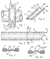
- Fig. 1 shows a bottom view of a pipe clip 1 of the type having a preformed pipe clip body which is fitted around a pipe 2.
- the illustrated pipe clip 1 has a circular pipe clip body which comprises two semicircular pipe clip halves 3. In the figure, only the bottom clip half 3 is visible.
- Each clip half 3 has a hinge means 4 at one end and a coupling flange 5 at the other end.
- the pipe clip halves 3 are hingedly coupled to one another by means of the respective hinge means 4.
- the clip body is opened by means of the hinge and fitted around the pipe 2.
- the coupling flanges 5 are then coupled to one another by means of a tightening screw 6 or another tightening means and the pipe clip 1 is secured around the pipe 2 by tightening the tightening screw 6.
- the pipe clip halves 3 of the pipe clip 1 are produced by bending a metal strip by means of a bending machine in a manner known per se to form a semicircular shape.
- the hinge means 4 and the flange 5 are also formed in a manner known per se by means of punching and bending.
- Figs 2 - 4 show a flat metal starting strip 3' from which the pipe clip half 3 is formed.
- the metal strip 3' is coated on the, viewed in the width direction, outermost regions 31' with a vibration-isolating coating 7' of, for example, rubber or another elastomeric material.
- the vibration-isolating coating 7' is applied to the metal strip 3' by passing the latter through an extrusion machine where liquid rubber or another vibration-isolating material is extruded onto the strip 3'.
- the outermost regions 31' of the metal strip 3' are provided with holes 8' which are arranged at a distance from one another in the longitudinal direction.
- coating material is only applied to the outermost regions 31' and the central region 32' located between the outermost regions 31' remains uncoated.
- the coating layer 7' is preferably thicker on that side 33' of the strip 3' which, in use, faces the pipe than on the opposite side 34', as can clearly be seen in Fig. 3 . It is also possible to provide the vibration-isolating material on the side 33' that is to face the pipe with longitudinal ridges (not shown) or the like to ensure better absorption of vibrations.
- the liquid coating material which is applied to that side 33' which, in use, is to face the pipe, and to the opposite side 34' of the strip 3' will flow through the holes 8' and, after solidification, form a connection between the coating material which is on both sides 33' and 34' of the metal strip 3'.
- the coating 7' is fixedly connected to the metal strip 3'.
- the metal strip 3' with the vibration-isolating coating 7' which has been extruded thereon, is preferably wound onto a reel again. Subsequently, the metal strip can be unwound again at another production location and cut to a specific length.
- the length of the cut metal strip is such that a clip half can be formed from it which is suitable for accommodating a pipe of a certain outer diameter.
- the ends of the cut metal strip 3' can be cleared of coating material at both ends.
- the ends of the metal strip which have been cleared of coating material are formed into a flange 5 and a hinge part 4 of the clip half 3 to be formed.
- the metal strip 3' which is still flat, is formed into the clip half 3 by means of a press device, with the strip 3' being bent into a semicircular shape.
- one or more reinforcement ridges may be formed in the central region 32 of the pipe clip body 3.
- Fig. 3a shows a cross section of a pipe clip half 103 in which the central region 132 is curved outwards, resulting in a relatively wide single reinforcement ridge 135. It is also possible to form several narrow ridges in the central region (not shown). The reinforcement ridges impart stiffness to the clip half 103.
- a pipe clip half 3 is obtained in which the outermost regions 8 are coated with vibration-isolating material 7 on that side which, in use, faces the pipe 2 and on the side facing away from the pipe 2.
- the pipe clip halves 3 can then be joined together and coupled to one another by means of their respective hinge means 4.
- a nut (not shown) can be welded, riveted or affixed in another way to the central region 32 of the top clip half. Affixing the nut can be carried out in a manner known per se in an automatic machine. It must be possible to screw the nut around the pipe clip 1 onto a threaded end provided on a ceiling or another support surface.
- the width of the central region 32' is preferably chosen in such a manner that a nut can be provided thereon.
- the pipe clip according to the invention is not necessarily constructed in the manner described.
- a clip with more than two clip parts would also be conceivable.
- the vibration-isolating coating can be applied to the metal strip.
- the layer is then connected to the metal, for example, by vulcanization.
Landscapes
- Engineering & Computer Science (AREA)
- General Engineering & Computer Science (AREA)
- Mechanical Engineering (AREA)
- Supports For Pipes And Cables (AREA)
- Vibration Prevention Devices (AREA)
- Clamps And Clips (AREA)
Claims (14)
- Rohrklemme (1) mit einem ringförmigen Rohrklemmenkörper aus einem Metallstreifen (3') zum Aufnehmen eines Rohrs (2), um letzteres an einer Wand, Decke oder einem anderen Träger anzubringen, in welchem ein Vibration isolierendes Material (7') wenigstens auf der Seite (33') des Rohrklemmenkörpers aufgebracht ist, die in Benutzung dem Rohr zugewandt ist, dadurch gekennzeichnet, dass, in Breitenrichtung des Metallstreifens gesehen, auf den am weitesten außen liegenden Regionen ein Vibration isolierendes Material wenigstens auf der Seite aufgebracht ist, die in Benutzung dem Rohr zugewandt ist und dass eine zentrale Region (32') des Metallstreifens, die zwischen den am weitesten außen liegenden Regionen liegt, auf der dem Rohr zugewandten Seite und der dem Rohr abgewandten Seite frei liegt.
- Rohrklemme nach Anspruch 1, in welchem Ausnehmungen oder Öffnungen (8') im Metallstreifen in regelmäßigen Abständen entlang der Länge der am weitesten außen liegenden Regionen des Metallstreifen vorgesehen sind, wobei die Ausnehmungen oder Öffnungen mit Vibration isolierendem Material gefüllt sind.
- Rohrklemmen nach Anspruch 1 oder 2, in welchem die am weitesten außen liegenden Regionen mit Vibration isolierendem Material über ihre Länge auf der Seite beschichtet sind, welche während der Benutzung dem Rohr zugewandt ist, und auf der Seite (34'), welche vom Rohr abgewandt ist.
- Rohrklemme nach Anspruch 2 oder 3, in welcher die Öffnungen als Löcher geformt sind, in welchen Anschlüsse aus Vibration isolierendem Material zwischen der Schicht aus Vibration isolierendem Material, die auf der während der Benutzung dem Rohr zugewandten Seite aufgebracht ist, bzw. der Schicht aus Vibration isolierendem Material, welche auf der dem Rohr abgewandten Seite aufgebracht ist, ausgebildet sind.
- Rohrklemme nach einem der vorhergehenden Ansprüche, in welcher das Vibration isolierende Material an den Rohrklemmenkörper gebunden ist.
- Rohrklemme nach einem der vorhergehenden Ansprüche, in welcher nach außen gebogene Spannflansche (4,5) auf den Enden des Rohrklemmenkörpers angeordnet sind, wobei die Spannflansche während der Benutzung mit Hilfe von Spannelementen, wie Spannbolzen (6) oder dgl., zusammengezogen werden können, wobei jeder der Spannflansche wenigstens auf der dem anderen Spannflansch zugewandten Seite frei von Vibration isolierendem Material ist.
- Rohrklemme nach einem der vorhergehenden Ansprüche, in welcher das Vibration isolierende Material eine auf dem Metallstreifen extrudierte Deckschicht umfasst.
- Rohrklemme nach einem der vorhergehenden Ansprüche, in welcher eine Mutter auf der Außenseite des Klemmenkörpers in der zentralen Region vorgesehen ist.
- Rohrklemme nach einem der vorhergehenden Ansprüche, in welcher die Breite der zentralen Region wenigstens der größten radialen Abmessung einer auf den Klemmenkörper anzubringenden Mutter entspricht.
- Rohrklemme nach einem der vorhergehenden Ansprüche, in welcher ein oder mehrere Verstärkungsrippen in der zentralen Region des Rohrklemmenkörpers ausgebildet sind.
- Rohrklemme nach einem oder mehreren vorhergehenden Ansprüche, in welcher das Vibration isolierende Material Gummi oder ein anderes elastomeres Material umfasst.
- Rohrklemme nach Anspruch 3, in welcher die Dicke der Deckschicht auf der dem Rohr während der Benutzung zugewandten Seite größer ist als die Dicke der Deckschicht auf der dem Rohr während der Benutzung abgewandten Seite.
- Rohrklemme nach einem der vorhergehenden Ansprüche, in welcher die Rohrklemme eine Mehrzahl von Klemmenteilen umfasst, die gelenkig miteinander verbunden sind.
- Verfahren zum Herstellen einer Rohrklemme (1), in welchem ein Metallstreifenmaterial (3') von einer Spule abgewickelt wird und auf wenigstens einer Seite auf am weitesten außen liegenden Regionen, gesehen in der Breitenrichtung des Streifens, mit einer Vibration isolierende Beschichtung (7') versehen wird; wobei eine zentrale Region (32') des Metallstreifens, die zwischen den äußersten Regionen liegt, unbeschichtet bleibt;
das Metallstreifenmaterial auf eine Länge zugeschnitten wird, um einen Metallstreifen (3') zu bilden, welcher zum Formen eines Rohrklemmenkörpers geeignet ist;
der Metallstreifen mit Hilfe einer Presseinrichtung in einen Klemmenkörper oder ein Klemmenteil geformt wird, wobei die Seite, welche mit der Vibration isolierenden Beschichtung auf den am weitesten außen liegenden Regionen versehen ist, mit der unbeschichteten zentralen Region zwischen diesen, in der Seite des Klemmenkörpers oder des Klemmenteils ausgebildet wird, die dem Rohr während der Benutzung zugewandt ist.
Priority Applications (2)
| Application Number | Priority Date | Filing Date | Title |
|---|---|---|---|
| EP09170685A EP2133617A1 (de) | 2006-06-27 | 2007-06-26 | Rohrschelle mit schwingungsisolierendem Einsatz |
| PL07747343T PL2032887T3 (pl) | 2006-06-27 | 2007-06-26 | Uchwyt do rur z wkładką izolującą wibracje |
Applications Claiming Priority (2)
| Application Number | Priority Date | Filing Date | Title |
|---|---|---|---|
| NL1032064A NL1032064C2 (nl) | 2006-06-27 | 2006-06-27 | Pijpbeugel met trillingisolerende inlaag. |
| PCT/NL2007/000161 WO2008002129A2 (en) | 2006-06-27 | 2007-06-26 | Pipe clip with vibration-isolating insert |
Related Child Applications (2)
| Application Number | Title | Priority Date | Filing Date |
|---|---|---|---|
| EP09170685A Division EP2133617A1 (de) | 2006-06-27 | 2007-06-26 | Rohrschelle mit schwingungsisolierendem Einsatz |
| EP09170685.3 Division-Into | 2009-09-18 |
Publications (2)
| Publication Number | Publication Date |
|---|---|
| EP2032887A2 EP2032887A2 (de) | 2009-03-11 |
| EP2032887B1 true EP2032887B1 (de) | 2010-02-17 |
Family
ID=37807961
Family Applications (2)
| Application Number | Title | Priority Date | Filing Date |
|---|---|---|---|
| EP07747343A Active EP2032887B1 (de) | 2006-06-27 | 2007-06-26 | Rohrklammer mit schwingungsisolierendem einsatz |
| EP09170685A Withdrawn EP2133617A1 (de) | 2006-06-27 | 2007-06-26 | Rohrschelle mit schwingungsisolierendem Einsatz |
Family Applications After (1)
| Application Number | Title | Priority Date | Filing Date |
|---|---|---|---|
| EP09170685A Withdrawn EP2133617A1 (de) | 2006-06-27 | 2007-06-26 | Rohrschelle mit schwingungsisolierendem Einsatz |
Country Status (11)
| Country | Link |
|---|---|
| US (1) | US8215593B2 (de) |
| EP (2) | EP2032887B1 (de) |
| AT (1) | ATE458164T1 (de) |
| CA (1) | CA2651531C (de) |
| DE (1) | DE602007004848D1 (de) |
| DK (1) | DK2032887T3 (de) |
| EA (1) | EA014487B1 (de) |
| ES (1) | ES2337950T3 (de) |
| NL (1) | NL1032064C2 (de) |
| PL (1) | PL2032887T3 (de) |
| WO (1) | WO2008002129A2 (de) |
Families Citing this family (16)
| Publication number | Priority date | Publication date | Assignee | Title |
|---|---|---|---|---|
| US10753627B1 (en) | 2005-07-13 | 2020-08-25 | Qc Manufacturing, Inc. | Air cooling system for a building structure |
| CA2655933C (en) * | 2006-06-23 | 2014-09-09 | Alethia Biotherapeutics Inc. | Polynucleotides and polypeptide sequences involved in cancer |
| US20120128661A1 (en) * | 2006-06-23 | 2012-05-24 | Alethia Biotherapeutics Inc. | Polynucleotide and polypeptide sequences involved in cancer |
| DE102007055906A1 (de) * | 2007-12-21 | 2009-06-25 | Hilti Aktiengesellschaft | Rohrschelle |
| EP2239488A1 (de) | 2009-04-08 | 2010-10-13 | NedShipGroup S.A. | Rohrsicherungssystem, Rohraufnahmeelement und Verwendung davon |
| US8857084B2 (en) | 2013-05-20 | 2014-10-14 | Gary Courter | Mobile advertising displays |
| NL2013596B1 (en) | 2014-10-08 | 2016-10-04 | Walraven Holding Bv J Van | Vibration isolating insert for a pipe clip and method for manufacturing such an insert. |
| AU2016218510B2 (en) * | 2015-02-13 | 2020-07-30 | J. Van Walraven Holding B.V. | Pipe clamp |
| US10940086B2 (en) * | 2015-11-12 | 2021-03-09 | Scalpal Llc | Bottle support and protective collar |
| DE102016111117A1 (de) * | 2016-06-17 | 2017-12-21 | Norma Germany Gmbh | Schelle mit thermischer Isolationsschicht |
| NL2017895B1 (en) * | 2016-11-30 | 2018-06-11 | Walraven Holding Bv J Van | Vibration isolating insert for a pipe clip |
| GB2559412B (en) * | 2017-02-06 | 2019-05-15 | Ford Global Tech Llc | Heatshield for a band clamp |
| WO2021102026A1 (en) | 2019-11-22 | 2021-05-27 | Qc Manufacturing, Inc. | Multifunction adaptive whole house fan system with motorized window |
| DE102020109118B3 (de) * | 2020-04-01 | 2021-03-25 | Matrix Module Gmbh | Abstandsstruktur, Sandwich-Konstruktion mit einer solchen Abstandsstruktur und Verfahren zur Herstellung einer solchen Abstandsstruktur |
| US12313194B1 (en) * | 2021-09-24 | 2025-05-27 | Rockler Companies, Inc. | Mountable dust hose connector system |
| DE202021106049U1 (de) * | 2021-11-04 | 2023-02-13 | Lemp GmbH & Co. KG | Abdeckelement für eine Rohrschelle und System zur Dachentwässerung von Gebäuden |
Family Cites Families (17)
| Publication number | Priority date | Publication date | Assignee | Title |
|---|---|---|---|---|
| US2387295A (en) * | 1943-09-14 | 1945-10-23 | Adel Prec Products Corp | Cushion for conduit and wire supporting clips |
| US2922733A (en) * | 1955-02-04 | 1960-01-26 | Richard A Henning | Cushion liner for a clamp operable at extreme temperatures |
| US2982505A (en) * | 1959-03-23 | 1961-05-02 | Gen Metals Corp | Adjustable diameter clips |
| US3159708A (en) * | 1960-07-25 | 1964-12-01 | Raychem Corp | Insulated clamp |
| US3165793A (en) * | 1961-06-05 | 1965-01-19 | Republic Ind Corp | Flange-gripping flexible sealingstrip carrier |
| US3419458A (en) * | 1964-05-07 | 1968-12-31 | Cee Bee Mfg Co Inc | Decorative extruded plastic stripping and laminated products including the same |
| GB1115527A (en) * | 1964-12-17 | 1968-05-29 | Happich Gmbh Gebr | Improvements in or relating to a profiled metal strip of u-shaped cross-section for use as a sealing strip |
| GB1173913A (en) | 1966-04-21 | 1969-12-10 | George Wilson Gas Meters Ltd | Perforated Strip |
| DE1951364U (de) | 1966-09-16 | 1966-12-08 | Kratzer F Mefa Duebel Gmbh | Mit einem elastisch nachgiebigen belag versehenes metallband. |
| US3706173A (en) * | 1969-08-15 | 1972-12-19 | Alfred E Taylor | Flexible molding strip and method of making same |
| DE7732253U1 (de) * | 1977-10-19 | 1978-05-11 | Pfitzmann, Wolfgang, 2090 Winsen | Rohrschelle |
| JPS5572413A (en) * | 1978-11-28 | 1980-05-31 | Inoue Mtp Co Ltd | Synthetic resin trim for automobile |
| US4318518A (en) * | 1980-03-20 | 1982-03-09 | Davis Lynwood A | Insulated hanger strap |
| US4441677A (en) * | 1982-04-02 | 1984-04-10 | Ta Mfg., Inc. | Clamp device |
| GB2181698B (en) * | 1985-10-17 | 1990-01-24 | Draftex Ind Ltd | Reinforcing carriers for trimming and sealing strips and the like |
| US5722131A (en) * | 1995-07-25 | 1998-03-03 | Sigma Tool & Machine | Clip for furniture springs, and method of manufacture |
| DE19716632A1 (de) | 1997-04-21 | 1998-10-22 | Fischer Artur Werke Gmbh | Rohrschelle |
-
2006
- 2006-06-27 NL NL1032064A patent/NL1032064C2/nl not_active IP Right Cessation
-
2007
- 2007-06-26 DE DE602007004848T patent/DE602007004848D1/de active Active
- 2007-06-26 PL PL07747343T patent/PL2032887T3/pl unknown
- 2007-06-26 WO PCT/NL2007/000161 patent/WO2008002129A2/en not_active Ceased
- 2007-06-26 EA EA200970060A patent/EA014487B1/ru not_active IP Right Cessation
- 2007-06-26 EP EP07747343A patent/EP2032887B1/de active Active
- 2007-06-26 DK DK07747343.7T patent/DK2032887T3/da active
- 2007-06-26 ES ES07747343T patent/ES2337950T3/es active Active
- 2007-06-26 US US12/306,927 patent/US8215593B2/en active Active
- 2007-06-26 CA CA2651531A patent/CA2651531C/en active Active
- 2007-06-26 AT AT07747343T patent/ATE458164T1/de not_active IP Right Cessation
- 2007-06-26 EP EP09170685A patent/EP2133617A1/de not_active Withdrawn
Also Published As
| Publication number | Publication date |
|---|---|
| NL1032064C2 (nl) | 2008-01-02 |
| CA2651531C (en) | 2014-09-23 |
| PL2032887T3 (pl) | 2010-07-30 |
| US8215593B2 (en) | 2012-07-10 |
| EP2032887A2 (de) | 2009-03-11 |
| WO2008002129A3 (en) | 2008-02-07 |
| ES2337950T3 (es) | 2010-04-30 |
| DK2032887T3 (da) | 2010-06-07 |
| EA014487B1 (ru) | 2010-12-30 |
| CA2651531A1 (en) | 2008-01-03 |
| US20090314904A1 (en) | 2009-12-24 |
| EA200970060A1 (ru) | 2009-06-30 |
| ATE458164T1 (de) | 2010-03-15 |
| WO2008002129A2 (en) | 2008-01-03 |
| EP2133617A1 (de) | 2009-12-16 |
| DE602007004848D1 (de) | 2010-04-01 |
Similar Documents
| Publication | Publication Date | Title |
|---|---|---|
| EP2032887B1 (de) | Rohrklammer mit schwingungsisolierendem einsatz | |
| US7909369B2 (en) | Coupling for joining two pipes | |
| FI82977C (fi) | Band, som har tillaempats att bilda ett roer genom att vrida bandet spiralfomigt. | |
| HUE026390T2 (en) | Mounting system for insulated equipment | |
| WO2016129993A1 (en) | Pipe clamp | |
| JP2022516459A (ja) | 非空気圧式タイヤのための可撓性金属ウェブ要素 | |
| US20030034650A1 (en) | Corrugated plastic pipe with fastening portion | |
| US6427727B1 (en) | Flexible hose length control system, exhaust system application, and manufacturing method | |
| CA2656907A1 (en) | Housing for tube coupling | |
| US7281689B1 (en) | Pipe support assembly | |
| US11685085B2 (en) | Tubular member sealing device | |
| EP3204681B1 (de) | Schwingungsisolierender einsatz für eine rohrschelle | |
| EP3548787B1 (de) | Schwingungsisolierender einsatz für eine rohrschelle | |
| KR200396397Y1 (ko) | 파형강관 연결장치 | |
| JP4542119B2 (ja) | 配管支持バンドの製造方法 | |
| US20190100251A1 (en) | Flexible members for sealing, baffling, or reinforcing | |
| CN2882985Y (zh) | 金属增强塑料带材及由其制造的金属增强塑料排水管 | |
| CN1072142C (zh) | 改进了连接结构的自行车手柄 | |
| CN220706770U (zh) | 一种新型复合缠绕管 | |
| JPH0346303Y2 (de) | ||
| FI84090C (fi) | Skyddsbeslag foer anvaendning byggnader. | |
| KR200335348Y1 (ko) | 파이프 연결용 압륜 | |
| CN115243963A (zh) | 车辆结构件的在与变速箱连接的部位处的增强体 | |
| KR20070010519A (ko) | 호스 고정용 클립 | |
| NL8501967A (nl) | Geluiddemper met een binnenbuis en een buitenbuis, alsmede werkwijze voor het vervaardigen van een dergelijke buis daarvoor. |
Legal Events
| Date | Code | Title | Description |
|---|---|---|---|
| PUAI | Public reference made under article 153(3) epc to a published international application that has entered the european phase |
Free format text: ORIGINAL CODE: 0009012 |
|
| 17P | Request for examination filed |
Effective date: 20081128 |
|
| AK | Designated contracting states |
Kind code of ref document: A2 Designated state(s): AT BE BG CH CY CZ DE DK EE ES FI FR GB GR HU IE IS IT LI LT LU LV MC MT NL PL PT RO SE SI SK TR |
|
| AX | Request for extension of the european patent |
Extension state: AL BA HR MK RS |
|
| 17Q | First examination report despatched |
Effective date: 20090406 |
|
| GRAP | Despatch of communication of intention to grant a patent |
Free format text: ORIGINAL CODE: EPIDOSNIGR1 |
|
| DAX | Request for extension of the european patent (deleted) | ||
| GRAS | Grant fee paid |
Free format text: ORIGINAL CODE: EPIDOSNIGR3 |
|
| GRAA | (expected) grant |
Free format text: ORIGINAL CODE: 0009210 |
|
| AK | Designated contracting states |
Kind code of ref document: B1 Designated state(s): AT BE BG CH CY CZ DE DK EE ES FI FR GB GR HU IE IS IT LI LT LU LV MC MT NL PL PT RO SE SI SK TR |
|
| REG | Reference to a national code |
Ref country code: GB Ref legal event code: FG4D |
|
| REG | Reference to a national code |
Ref country code: CH Ref legal event code: EP |
|
| REG | Reference to a national code |
Ref country code: IE Ref legal event code: FG4D |
|
| REF | Corresponds to: |
Ref document number: 602007004848 Country of ref document: DE Date of ref document: 20100401 Kind code of ref document: P |
|
| REG | Reference to a national code |
Ref country code: NL Ref legal event code: T3 |
|
| REG | Reference to a national code |
Ref country code: ES Ref legal event code: FG2A Ref document number: 2337950 Country of ref document: ES Kind code of ref document: T3 |
|
| REG | Reference to a national code |
Ref country code: SE Ref legal event code: TRGR |
|
| REG | Reference to a national code |
Ref country code: DK Ref legal event code: T3 |
|
| LTIE | Lt: invalidation of european patent or patent extension |
Effective date: 20100217 |
|
| PG25 | Lapsed in a contracting state [announced via postgrant information from national office to epo] |
Ref country code: IS Free format text: LAPSE BECAUSE OF FAILURE TO SUBMIT A TRANSLATION OF THE DESCRIPTION OR TO PAY THE FEE WITHIN THE PRESCRIBED TIME-LIMIT Effective date: 20100617 Ref country code: LT Free format text: LAPSE BECAUSE OF FAILURE TO SUBMIT A TRANSLATION OF THE DESCRIPTION OR TO PAY THE FEE WITHIN THE PRESCRIBED TIME-LIMIT Effective date: 20100217 Ref country code: PT Free format text: LAPSE BECAUSE OF FAILURE TO SUBMIT A TRANSLATION OF THE DESCRIPTION OR TO PAY THE FEE WITHIN THE PRESCRIBED TIME-LIMIT Effective date: 20100617 |
|
| REG | Reference to a national code |
Ref country code: PL Ref legal event code: T3 |
|
| PG25 | Lapsed in a contracting state [announced via postgrant information from national office to epo] |
Ref country code: LV Free format text: LAPSE BECAUSE OF FAILURE TO SUBMIT A TRANSLATION OF THE DESCRIPTION OR TO PAY THE FEE WITHIN THE PRESCRIBED TIME-LIMIT Effective date: 20100217 Ref country code: FI Free format text: LAPSE BECAUSE OF FAILURE TO SUBMIT A TRANSLATION OF THE DESCRIPTION OR TO PAY THE FEE WITHIN THE PRESCRIBED TIME-LIMIT Effective date: 20100217 Ref country code: AT Free format text: LAPSE BECAUSE OF FAILURE TO SUBMIT A TRANSLATION OF THE DESCRIPTION OR TO PAY THE FEE WITHIN THE PRESCRIBED TIME-LIMIT Effective date: 20100217 Ref country code: SI Free format text: LAPSE BECAUSE OF FAILURE TO SUBMIT A TRANSLATION OF THE DESCRIPTION OR TO PAY THE FEE WITHIN THE PRESCRIBED TIME-LIMIT Effective date: 20100217 |
|
| PG25 | Lapsed in a contracting state [announced via postgrant information from national office to epo] |
Ref country code: GR Free format text: LAPSE BECAUSE OF FAILURE TO SUBMIT A TRANSLATION OF THE DESCRIPTION OR TO PAY THE FEE WITHIN THE PRESCRIBED TIME-LIMIT Effective date: 20100518 Ref country code: EE Free format text: LAPSE BECAUSE OF FAILURE TO SUBMIT A TRANSLATION OF THE DESCRIPTION OR TO PAY THE FEE WITHIN THE PRESCRIBED TIME-LIMIT Effective date: 20100217 Ref country code: CY Free format text: LAPSE BECAUSE OF FAILURE TO SUBMIT A TRANSLATION OF THE DESCRIPTION OR TO PAY THE FEE WITHIN THE PRESCRIBED TIME-LIMIT Effective date: 20100217 Ref country code: RO Free format text: LAPSE BECAUSE OF FAILURE TO SUBMIT A TRANSLATION OF THE DESCRIPTION OR TO PAY THE FEE WITHIN THE PRESCRIBED TIME-LIMIT Effective date: 20100217 |
|
| PG25 | Lapsed in a contracting state [announced via postgrant information from national office to epo] |
Ref country code: BG Free format text: LAPSE BECAUSE OF FAILURE TO SUBMIT A TRANSLATION OF THE DESCRIPTION OR TO PAY THE FEE WITHIN THE PRESCRIBED TIME-LIMIT Effective date: 20100517 Ref country code: SK Free format text: LAPSE BECAUSE OF FAILURE TO SUBMIT A TRANSLATION OF THE DESCRIPTION OR TO PAY THE FEE WITHIN THE PRESCRIBED TIME-LIMIT Effective date: 20100217 |
|
| PLBE | No opposition filed within time limit |
Free format text: ORIGINAL CODE: 0009261 |
|
| STAA | Information on the status of an ep patent application or granted ep patent |
Free format text: STATUS: NO OPPOSITION FILED WITHIN TIME LIMIT |
|
| 26N | No opposition filed |
Effective date: 20101118 |
|
| PG25 | Lapsed in a contracting state [announced via postgrant information from national office to epo] |
Ref country code: MC Free format text: LAPSE BECAUSE OF NON-PAYMENT OF DUE FEES Effective date: 20100630 |
|
| PG25 | Lapsed in a contracting state [announced via postgrant information from national office to epo] |
Ref country code: MT Free format text: LAPSE BECAUSE OF FAILURE TO SUBMIT A TRANSLATION OF THE DESCRIPTION OR TO PAY THE FEE WITHIN THE PRESCRIBED TIME-LIMIT Effective date: 20100217 Ref country code: IE Free format text: LAPSE BECAUSE OF NON-PAYMENT OF DUE FEES Effective date: 20100626 |
|
| REG | Reference to a national code |
Ref country code: CH Ref legal event code: PL |
|
| PG25 | Lapsed in a contracting state [announced via postgrant information from national office to epo] |
Ref country code: CH Free format text: LAPSE BECAUSE OF NON-PAYMENT OF DUE FEES Effective date: 20110630 Ref country code: LI Free format text: LAPSE BECAUSE OF NON-PAYMENT OF DUE FEES Effective date: 20110630 |
|
| PG25 | Lapsed in a contracting state [announced via postgrant information from national office to epo] |
Ref country code: HU Free format text: LAPSE BECAUSE OF FAILURE TO SUBMIT A TRANSLATION OF THE DESCRIPTION OR TO PAY THE FEE WITHIN THE PRESCRIBED TIME-LIMIT Effective date: 20100818 Ref country code: LU Free format text: LAPSE BECAUSE OF NON-PAYMENT OF DUE FEES Effective date: 20100626 |
|
| PG25 | Lapsed in a contracting state [announced via postgrant information from national office to epo] |
Ref country code: TR Free format text: LAPSE BECAUSE OF FAILURE TO SUBMIT A TRANSLATION OF THE DESCRIPTION OR TO PAY THE FEE WITHIN THE PRESCRIBED TIME-LIMIT Effective date: 20100217 |
|
| REG | Reference to a national code |
Ref country code: FR Ref legal event code: PLFP Year of fee payment: 10 |
|
| REG | Reference to a national code |
Ref country code: FR Ref legal event code: PLFP Year of fee payment: 11 |
|
| REG | Reference to a national code |
Ref country code: FR Ref legal event code: PLFP Year of fee payment: 12 |
|
| PGFP | Annual fee paid to national office [announced via postgrant information from national office to epo] |
Ref country code: PL Payment date: 20250613 Year of fee payment: 19 Ref country code: DE Payment date: 20250618 Year of fee payment: 19 |
|
| PGFP | Annual fee paid to national office [announced via postgrant information from national office to epo] |
Ref country code: GB Payment date: 20250620 Year of fee payment: 19 Ref country code: DK Payment date: 20250618 Year of fee payment: 19 |
|
| PGFP | Annual fee paid to national office [announced via postgrant information from national office to epo] |
Ref country code: NL Payment date: 20250624 Year of fee payment: 19 Ref country code: BE Payment date: 20250619 Year of fee payment: 19 |
|
| PGFP | Annual fee paid to national office [announced via postgrant information from national office to epo] |
Ref country code: FR Payment date: 20250627 Year of fee payment: 19 |
|
| PGFP | Annual fee paid to national office [announced via postgrant information from national office to epo] |
Ref country code: CZ Payment date: 20250613 Year of fee payment: 19 |
|
| PGFP | Annual fee paid to national office [announced via postgrant information from national office to epo] |
Ref country code: SE Payment date: 20250618 Year of fee payment: 19 |
|
| PGFP | Annual fee paid to national office [announced via postgrant information from national office to epo] |
Ref country code: ES Payment date: 20250718 Year of fee payment: 19 |
|
| PGFP | Annual fee paid to national office [announced via postgrant information from national office to epo] |
Ref country code: IT Payment date: 20250630 Year of fee payment: 19 |