EP2032186B1 - Hand-held aspiration syringe and methods - Google Patents
Hand-held aspiration syringe and methods Download PDFInfo
- Publication number
- EP2032186B1 EP2032186B1 EP07794711.7A EP07794711A EP2032186B1 EP 2032186 B1 EP2032186 B1 EP 2032186B1 EP 07794711 A EP07794711 A EP 07794711A EP 2032186 B1 EP2032186 B1 EP 2032186B1
- Authority
- EP
- European Patent Office
- Prior art keywords
- barrel
- syringe
- plunger
- handle
- receptacle
- Prior art date
- Legal status (The legal status is an assumption and is not a legal conclusion. Google has not performed a legal analysis and makes no representation as to the accuracy of the status listed.)
- Not-in-force
Links
- 238000000034 method Methods 0.000 title description 3
- 239000012530 fluid Substances 0.000 claims description 10
- 210000003811 finger Anatomy 0.000 claims description 6
- 210000003813 thumb Anatomy 0.000 claims description 5
- 239000000463 material Substances 0.000 description 7
- 230000008878 coupling Effects 0.000 description 6
- 238000010168 coupling process Methods 0.000 description 6
- 238000005859 coupling reaction Methods 0.000 description 6
- 238000004891 communication Methods 0.000 description 4
- 230000002787 reinforcement Effects 0.000 description 4
- 230000008901 benefit Effects 0.000 description 3
- 239000000243 solution Substances 0.000 description 3
- 238000001574 biopsy Methods 0.000 description 2
- 230000014759 maintenance of location Effects 0.000 description 2
- 238000004519 manufacturing process Methods 0.000 description 2
- 229920000515 polycarbonate Polymers 0.000 description 2
- 239000000523 sample Substances 0.000 description 2
- 229920004142 LEXAN™ Polymers 0.000 description 1
- 239000004425 Makrolon Substances 0.000 description 1
- FAPWRFPIFSIZLT-UHFFFAOYSA-M Sodium chloride Chemical compound [Na+].[Cl-] FAPWRFPIFSIZLT-UHFFFAOYSA-M 0.000 description 1
- 208000007536 Thrombosis Diseases 0.000 description 1
- 230000003444 anaesthetic effect Effects 0.000 description 1
- 238000005452 bending Methods 0.000 description 1
- 239000012472 biological sample Substances 0.000 description 1
- 239000008280 blood Substances 0.000 description 1
- 210000004369 blood Anatomy 0.000 description 1
- 210000001124 body fluid Anatomy 0.000 description 1
- 230000000295 complement effect Effects 0.000 description 1
- 150000001875 compounds Chemical class 0.000 description 1
- 229940039231 contrast media Drugs 0.000 description 1
- 239000002872 contrast media Substances 0.000 description 1
- 238000006073 displacement reaction Methods 0.000 description 1
- 239000003814 drug Substances 0.000 description 1
- 238000001802 infusion Methods 0.000 description 1
- 238000001746 injection moulding Methods 0.000 description 1
- 229910052751 metal Inorganic materials 0.000 description 1
- 239000002184 metal Substances 0.000 description 1
- 150000002739 metals Chemical class 0.000 description 1
- 239000004033 plastic Substances 0.000 description 1
- 229920003023 plastic Polymers 0.000 description 1
- 239000004417 polycarbonate Substances 0.000 description 1
- 229920000642 polymer Polymers 0.000 description 1
- 229920001296 polysiloxane Polymers 0.000 description 1
- 230000008569 process Effects 0.000 description 1
- 230000002285 radioactive effect Effects 0.000 description 1
- 229910001220 stainless steel Inorganic materials 0.000 description 1
- 239000010935 stainless steel Substances 0.000 description 1
- -1 stainless steel Chemical class 0.000 description 1
- 239000000126 substance Substances 0.000 description 1
Images


Classifications
-
- A—HUMAN NECESSITIES
- A61—MEDICAL OR VETERINARY SCIENCE; HYGIENE
- A61B—DIAGNOSIS; SURGERY; IDENTIFICATION
- A61B5/00—Measuring for diagnostic purposes; Identification of persons
- A61B5/15—Devices for taking samples of blood
- A61B5/153—Devices specially adapted for taking samples of venous or arterial blood, e.g. with syringes
-
- A—HUMAN NECESSITIES
- A61—MEDICAL OR VETERINARY SCIENCE; HYGIENE
- A61B—DIAGNOSIS; SURGERY; IDENTIFICATION
- A61B10/00—Instruments for taking body samples for diagnostic purposes; Other methods or instruments for diagnosis, e.g. for vaccination diagnosis, sex determination or ovulation-period determination; Throat striking implements
- A61B10/0045—Devices for taking samples of body liquids
-
- A—HUMAN NECESSITIES
- A61—MEDICAL OR VETERINARY SCIENCE; HYGIENE
- A61B—DIAGNOSIS; SURGERY; IDENTIFICATION
- A61B5/00—Measuring for diagnostic purposes; Identification of persons
- A61B5/15—Devices for taking samples of blood
- A61B5/150007—Details
- A61B5/150015—Source of blood
- A61B5/15003—Source of blood for venous or arterial blood
-
- A—HUMAN NECESSITIES
- A61—MEDICAL OR VETERINARY SCIENCE; HYGIENE
- A61B—DIAGNOSIS; SURGERY; IDENTIFICATION
- A61B5/00—Measuring for diagnostic purposes; Identification of persons
- A61B5/15—Devices for taking samples of blood
- A61B5/150007—Details
- A61B5/150206—Construction or design features not otherwise provided for; manufacturing or production; packages; sterilisation of piercing element, piercing device or sampling device
- A61B5/150221—Valves
-
- A—HUMAN NECESSITIES
- A61—MEDICAL OR VETERINARY SCIENCE; HYGIENE
- A61B—DIAGNOSIS; SURGERY; IDENTIFICATION
- A61B5/00—Measuring for diagnostic purposes; Identification of persons
- A61B5/15—Devices for taking samples of blood
- A61B5/150007—Details
- A61B5/150206—Construction or design features not otherwise provided for; manufacturing or production; packages; sterilisation of piercing element, piercing device or sampling device
- A61B5/150236—Pistons, i.e. cylindrical bodies that sit inside the syringe barrel, typically with an air tight seal, and slide in the barrel to create a vacuum or to expel blood
-
- A—HUMAN NECESSITIES
- A61—MEDICAL OR VETERINARY SCIENCE; HYGIENE
- A61B—DIAGNOSIS; SURGERY; IDENTIFICATION
- A61B5/00—Measuring for diagnostic purposes; Identification of persons
- A61B5/15—Devices for taking samples of blood
- A61B5/150007—Details
- A61B5/150206—Construction or design features not otherwise provided for; manufacturing or production; packages; sterilisation of piercing element, piercing device or sampling device
- A61B5/150244—Rods for actuating or driving the piston, i.e. the cylindrical body that sits inside the syringe barrel, typically with an air tight seal, and slides in the barrel to create a vacuum or to expel blood
-
- A—HUMAN NECESSITIES
- A61—MEDICAL OR VETERINARY SCIENCE; HYGIENE
- A61B—DIAGNOSIS; SURGERY; IDENTIFICATION
- A61B5/00—Measuring for diagnostic purposes; Identification of persons
- A61B5/15—Devices for taking samples of blood
- A61B5/150007—Details
- A61B5/150206—Construction or design features not otherwise provided for; manufacturing or production; packages; sterilisation of piercing element, piercing device or sampling device
- A61B5/150259—Improved gripping, e.g. with high friction pattern or projections on the housing surface or an ergonometric shape
-
- A—HUMAN NECESSITIES
- A61—MEDICAL OR VETERINARY SCIENCE; HYGIENE
- A61M—DEVICES FOR INTRODUCING MEDIA INTO, OR ONTO, THE BODY; DEVICES FOR TRANSDUCING BODY MEDIA OR FOR TAKING MEDIA FROM THE BODY; DEVICES FOR PRODUCING OR ENDING SLEEP OR STUPOR
- A61M1/00—Suction or pumping devices for medical purposes; Devices for carrying-off, for treatment of, or for carrying-over, body-liquids; Drainage systems
- A61M1/64—Containers with integrated suction means
- A61M1/67—Containers incorporating a piston-type member to create suction, e.g. syringes
-
- A—HUMAN NECESSITIES
- A61—MEDICAL OR VETERINARY SCIENCE; HYGIENE
- A61M—DEVICES FOR INTRODUCING MEDIA INTO, OR ONTO, THE BODY; DEVICES FOR TRANSDUCING BODY MEDIA OR FOR TAKING MEDIA FROM THE BODY; DEVICES FOR PRODUCING OR ENDING SLEEP OR STUPOR
- A61M5/00—Devices for bringing media into the body in a subcutaneous, intra-vascular or intramuscular way; Accessories therefor, e.g. filling or cleaning devices, arm-rests
- A61M5/178—Syringes
- A61M5/31—Details
- A61M5/3129—Syringe barrels
- A61M5/3137—Specially designed finger grip means, e.g. for easy manipulation of the syringe rod
-
- A—HUMAN NECESSITIES
- A61—MEDICAL OR VETERINARY SCIENCE; HYGIENE
- A61M—DEVICES FOR INTRODUCING MEDIA INTO, OR ONTO, THE BODY; DEVICES FOR TRANSDUCING BODY MEDIA OR FOR TAKING MEDIA FROM THE BODY; DEVICES FOR PRODUCING OR ENDING SLEEP OR STUPOR
- A61M5/00—Devices for bringing media into the body in a subcutaneous, intra-vascular or intramuscular way; Accessories therefor, e.g. filling or cleaning devices, arm-rests
- A61M5/178—Syringes
- A61M5/31—Details
- A61M2005/3128—Incorporating one-way valves, e.g. pressure-relief or non-return valves
-
- A—HUMAN NECESSITIES
- A61—MEDICAL OR VETERINARY SCIENCE; HYGIENE
- A61M—DEVICES FOR INTRODUCING MEDIA INTO, OR ONTO, THE BODY; DEVICES FOR TRANSDUCING BODY MEDIA OR FOR TAKING MEDIA FROM THE BODY; DEVICES FOR PRODUCING OR ENDING SLEEP OR STUPOR
- A61M5/00—Devices for bringing media into the body in a subcutaneous, intra-vascular or intramuscular way; Accessories therefor, e.g. filling or cleaning devices, arm-rests
- A61M5/178—Syringes
- A61M5/31—Details
- A61M5/3129—Syringe barrels
- A61M5/3137—Specially designed finger grip means, e.g. for easy manipulation of the syringe rod
- A61M2005/3139—Finger grips not integrally formed with the syringe barrel, e.g. using adapter with finger grips
-
- A—HUMAN NECESSITIES
- A61—MEDICAL OR VETERINARY SCIENCE; HYGIENE
- A61M—DEVICES FOR INTRODUCING MEDIA INTO, OR ONTO, THE BODY; DEVICES FOR TRANSDUCING BODY MEDIA OR FOR TAKING MEDIA FROM THE BODY; DEVICES FOR PRODUCING OR ENDING SLEEP OR STUPOR
- A61M5/00—Devices for bringing media into the body in a subcutaneous, intra-vascular or intramuscular way; Accessories therefor, e.g. filling or cleaning devices, arm-rests
- A61M5/178—Syringes
- A61M5/31—Details
- A61M5/315—Pistons; Piston-rods; Guiding, blocking or restricting the movement of the rod or piston; Appliances on the rod for facilitating dosing ; Dosing mechanisms
- A61M5/31511—Piston or piston-rod constructions, e.g. connection of piston with piston-rod
- A61M2005/3152—Piston or piston-rod constructions, e.g. connection of piston with piston-rod including gearings to multiply or attenuate the piston displacing force
-
- A—HUMAN NECESSITIES
- A61—MEDICAL OR VETERINARY SCIENCE; HYGIENE
- A61M—DEVICES FOR INTRODUCING MEDIA INTO, OR ONTO, THE BODY; DEVICES FOR TRANSDUCING BODY MEDIA OR FOR TAKING MEDIA FROM THE BODY; DEVICES FOR PRODUCING OR ENDING SLEEP OR STUPOR
- A61M5/00—Devices for bringing media into the body in a subcutaneous, intra-vascular or intramuscular way; Accessories therefor, e.g. filling or cleaning devices, arm-rests
- A61M5/007—Devices for bringing media into the body in a subcutaneous, intra-vascular or intramuscular way; Accessories therefor, e.g. filling or cleaning devices, arm-rests for contrast media
-
- A—HUMAN NECESSITIES
- A61—MEDICAL OR VETERINARY SCIENCE; HYGIENE
- A61M—DEVICES FOR INTRODUCING MEDIA INTO, OR ONTO, THE BODY; DEVICES FOR TRANSDUCING BODY MEDIA OR FOR TAKING MEDIA FROM THE BODY; DEVICES FOR PRODUCING OR ENDING SLEEP OR STUPOR
- A61M5/00—Devices for bringing media into the body in a subcutaneous, intra-vascular or intramuscular way; Accessories therefor, e.g. filling or cleaning devices, arm-rests
- A61M5/178—Syringes
- A61M5/20—Automatic syringes, e.g. with automatically actuated piston rod, with automatic needle injection, filling automatically
- A61M5/204—Automatic syringes, e.g. with automatically actuated piston rod, with automatic needle injection, filling automatically connected to external reservoirs for multiple refilling
-
- A—HUMAN NECESSITIES
- A61—MEDICAL OR VETERINARY SCIENCE; HYGIENE
- A61M—DEVICES FOR INTRODUCING MEDIA INTO, OR ONTO, THE BODY; DEVICES FOR TRANSDUCING BODY MEDIA OR FOR TAKING MEDIA FROM THE BODY; DEVICES FOR PRODUCING OR ENDING SLEEP OR STUPOR
- A61M5/00—Devices for bringing media into the body in a subcutaneous, intra-vascular or intramuscular way; Accessories therefor, e.g. filling or cleaning devices, arm-rests
- A61M5/178—Syringes
- A61M5/31—Details
- A61M5/3148—Means for causing or aiding aspiration or plunger retraction
Definitions
- the present invention relates generally to an aspiration apparatus for facilitating the movement of a plunger of a syringe through a barrel of the syringe and, more particularly, to hand-held, hand operated apparatus that facilitate the movement of a plunger through a syringe barrel. More specifically, the present invention relates to hand-held apparatus with scissor grip type leveraged triggering systems that force a plunger of a syringe through the length of the barrel of the syringe.
- syringes for aspirating biological samples from the bodies of subjects.
- the barrel of a syringe is placed in communication with a desired location of a subject's body, then a vacuum is created within the barrel of a syringe by pulling a plunger of the syringe toward a proximal end of the syringe (i.e., toward the syringe user, away from the body of the subject).
- a vacuum is formed within the barrel of a syringe, fluid from the desired location is drawn into the syringe.
- syringes that are configured to reduce a user's exertion are also typically configured for fluid delivery rather than for aspiration.
- aspiration is effected by holding the barrel of the syringe with one hand while pulling the plunger with another hand. Similar actions must be taken when many other types of manually operated devices are used to facilitate aspiration with a syringe.
- syringes that are configured to be held, or suspended, and operated by the same hand of a user and that may be comfortably operated.
- Aspiration syringes are to be distinguished from injector syringes or infusion syringes, such as the syringes discloses in WO 02/094343A2 , US 5,964,736 , US 6,030,368 or US 5,733,258 .
- the present invention includes an aspiration apparatus according to claim 1. It comprises a syringe and a handle that is configured to effectively reduce the amount of force that must be applied by a user
- a withdrawal element e.g ., a needle, catheter, etc.
- a sample may then be drawn through the withdrawal element and into the barrel by moving the first and second members of the handle toward one another.
- the barrel may then be removed from communication with the withdrawal element, and the sample expelled from the barrel by moving the members of the handle away from each other.
- FIG. 1 illustrates an exemplary embodiment of an aspiration apparatus, here a syringe 10, incorporating teachings of the present invention.
- Syringe 10 includes a barrel 20, a plunger 30 associated with barrel 20, and a scissor-grip handle 40 which causes plunger 30 to move longitudinally relative to barrel 20.
- barrel 20 and plunger 30 may be removable from handle 40 to facilitate the replacement of these elements and the reuse of handle 40.
- Barrel 20 of syringe 10 is an elongate member with a hollow interior extending through the length thereof. Along the majority of its length, barrel 20 is substantially uniform in both cross-sectional shape and cross-sectional dimensions. The region of barrel 20 having such substantial cross-sectional uniformity is referred to herein as body 22. As depicted, body 22 extends from a proximal end 21p of barrel 20 to a tapered section or region 24 thereof. A syringe tip 25 is located on the opposite side of tapered section 24, at the distal end 21 d of barrel 20.
- OD20 the distances across opposed points of various cross-sections taken transverse to longitudinal axis A B of barrel 20 on the outer surface of barrel 20 or the outer diameter of barrel 20 are collectively referred to herein as OD20.
- ID20 The corresponding distances across opposed points of various cross-sections taken transverse to longitudinal axis A B on the inner surface of barrel 20 or the inner diameter of barrel 20 are collectively referred to herein as ID20.
- both OD20A and ID20A remain substantially the same along the substantial length of a body 22 of barrel 20.
- OD20 and ID20 which are respectively depicted at one location along the length of tapered region 24 as OD20B and ID20B, gradually (either linearly or along a curve) decrease from the sizes of OD20A and ID20A of body 22 to the much smaller sizes OD20C and ID20C of syringe tip 25.
- the sizes of OD20C and ID20C are again substantially constant.
- taper of tapered region 24 occur at an angle of about 15° to longitudinal axis A B of barrel 20. Other taper angles are, however, also within the scope of the present invention.
- the volume of receptacle 23 is preferably suitable for the desired use of syringe 10 ( FIG. 1 ).
- barrel 20 may include a receptacle 23 with a relative small volume (e.g., 5 cubic centimeters ("cc"), 10 cc, etc.).
- cc cubic centimeters
- the volume of receptacle 23 may also be larger (e.g., 20cc, 30cc, 60cc, etc.).
- receptacle 23 of barrel 20 may have other standard syringe volumes or a volume that is tailored to a specific use for syringe 10.
- Lumen 26 may have a diameter of as small as about 1mm (0.40 inch) or smaller.
- syringe tips 25 with different sizes of lumens 26 are within the scope of the present invention, as the size of a lumen 26 depends at least partially upon the gauge of a needle or the lumen size of a catheter to be coupled with syringe tip 25.
- syringe tip 25 includes a coupling member 27 at or near the distal end 21d of barrel 20.
- FIG. 1 depicts coupling member 27 as including a cylindrically shaped recess that extends partially into syringe tip 25
- coupling members of other configurations including, without limitation, threaded or nonthreaded coupling members that facilitate the coupling of a needle, catheter, or other member to an outer surface of syringe tip 25, are also within the scope of the present invention.
- a variation of barrel 20' may include an aspiration port 80 proximate syringe tip 25.
- Aspiration port 80 facilitates the introduction of a fluid, such as a saline solution, medicine, anesthetic, indicator solution (e.g ., dye, radioactive solution, radioopaque solution or x-ray contrast media, etc.), other chemical compound, or the like from an external source into receptacle 23 of barrel 20.
- Aspiration port 80 is depicted as comprising a cylindrical protrusion 81, which is configured to have a length of tubing coupled thereto, and a lumen 82 that extends through protrusion 81. and communicates with lumen 26 of syringe tip 25.
- aspiration port 80 may include a valve 83, such as a stop cock type valve, which opens and closes lumen 82.
- valve 83 such as a stop cock type valve
- barrel 20 also includes a handle connection element 28.
- handle connection element 28 extends from body 22 at proximal end 21 p of barrel 20 and includes an aperture formed therethrough. The aperture is sized and configured to receive a hinge element 70 and, thus, to facilitate the connection of a member of handle 40 to barrel 20.
- a handle connection element 28" may include features on opposite sides of barrel 20.
- Such a connection point arrangement places the pivotal points that are established by connection elements 59 and 69" that are associated with handle 40 members 50 and 60, respectively, substantially in-line with axes A B of barrel 20 and A p of plunger 30.
- FIG. 1 depicts barrel 20, receptacle 23, and lumen 26 as having substantially cylindrical shapes with circular cross-sections taken transverse to a longitudinal axis A B of barrel 20, syringe barrels with any other suitable cross-sectional shapes (e.g ., ovals, ellipses, polygons, etc.) are also within the scope of the present invention.
- plunger 30 is an elongate member with dimensions that permit plunger 30 to be inserted into receptacle 23 of barrel 20 through proximal end 21p thereof.
- Plunger 30 includes a body 32 and a head 34 at the distal, end 31d of body 32.
- the proximal end 31p of body 32 and, thus, of plunger 30 is configured to have force applied thereto to facilitate movement of plunger 30 in both directions along a longitudinal axis A p of plunger 30.
- Head 34 of plunger 30 preferably comprises a somewhat deformable, resilient member.
- head 34 may be formed from silicone or any other resilient polymer (i.e ., rubber) that is suitable for use in medical applications.
- the shape of head 34 is preferably substantially complementary to a shape of the portion of receptacle 23 of barrel 20 that is located within tapered region 24 and a portion of body 22 adjacent thereto.
- the size of head 34 is preferably substantially the same as or somewhat larger than the correspondingly shaped portion of receptacle 23 so as to facilitate the substantial displacement of fluid from receptacle 23 as plunger 30 is fully inserted therein.
- the length of plunger 30 is greater than the combined lengths of body 22 and tapered region 24 of barrel 20.
- body 32 of plunger 30 is preferably formed from a more rigid material than that of head 34.
- head 34 preferably includes a receptacle (not shown) that is configured to receive a corresponding head connection protrusion (not shown) at the distal end of body 32, as known in the art.
- Proximal end 31p of plunger 30 includes a handle connection element 38.
- Handle connection element 38 includes an aperture formed through body 32 of plunger 30 at a location that facilitates the pivotal connection of a member of handle 40 thereto by way of a hinge element 70.
- proximal end 31p of plunger 30 may include a secondary movement element 36, such as a loop or another member by which an individual may cause plunger 30 to move in one or both directions along longitudinal axis A p thereof.
- a secondary movement element 36 such as a loop or another member by which an individual may cause plunger 30 to move in one or both directions along longitudinal axis A p thereof.
- handle 40 includes two elongate members, a first member 60 and a second member 50.
- First member 60 and second member 50 are pivotally connected with one another in a manner that, along with the shapes of first and second members 60 and 50, provides leverage, or a mechanical advantage, so as to decrease the amount of force that must be exerted by a user's hand to move plunger 30 relative to barrel 20.
- First member 60 which is configured to be held with a user's fingers, includes a gripping end 62 and a barrel attachment end 68.
- first member 60 includes pivotal connection element 66 positioned at a central region 65 thereof, which is located substantially centrally along the length thereof, to facilitate connection of first member 50 to second member 50 of handle 40.
- Pivotal connection element 66 includes an aperture that has a circular shape and that receives a hinge element 70, or pivot pin, which, in turn, connects first member 60 and second member 50 to one another.
- first member 60 includes an elongated loop 63 along gripping end 62, through which an individual's fingers may be inserted.
- gripping end 62 may include a finger grip 64 that is contoured so as to comfortably receive the fingers of a user.
- Barrel attachment end 68 includes ( e.g., terminates at) a barrel connection element 69 that facilitates the pivotal connection of second member 60 to the corresponding handle connection element 28 of barrel 20.
- barrel connection element 69 comprises an aperture that is configured to receive a hinge element 70.
- Second member 60 and barrel 20 are pivotally connected to one another by properly positioning barrel attachment end 68 and handle connection element 28 against one another, with the apertures thereof in alignment, and inserting a single hinge element 70 through both barrel connection element 69 and handle connection element 28.
- Hinge element 70 preferably includes an enlarged head 71 at each end thereof to maintain the assembled, pivotal relationship of barrel 20 and second member 60.
- other known types of pivotal connection arrangements between barrel 20 and second member 60 and their corresponding elements are also within the scope of the present invention.
- First member 60 is bent, or angled, at some point along the length thereof, between gripping end 62 and plunger attachment end 68, to at least partially provide the desired amount of leverage for forcing plunger 30 to move longitudinally through ( e.g ., out of) receptacle 23 of barrel 20.
- first member 60 is angled at central region 65 so that gripping end 62 thereof extends away from second member 50.
- FIG. 1 depicts gripping end 62 and plunger attachment end 68 as being oriented at an angle of about 90° relative to one another, other angles and bend locations are also within the scope of the present invention.
- second member 50 of handle 40 is an elongate member that is configured to be held by a subject's palm or thumb.
- Second member 50 includes a gripping end 52 and plunger attachment end 58, as well as a central region 55 located between gripping end 52 and plunger attachment end 58.
- Gripping end 52 of first member 50 may include a thumb loop 53 through which the thumb of a user of syringe 10 may be inserted.
- Central region 55 of second member 50 includes a pivotal connection element 56 that corresponds to pivotal connection element 66 of first member 60.
- Pivotal connection element 56 may comprise an aperture formed through central region 55 and configured to receive hinge element 70.
- hinge element 70 may be inserted through the apertures to pivotally connect first and second members 60 and 50 to one another.
- Hinge element 70 preferably includes an enlarged head 71 at each end thereof to maintain the assembled, pivotal relationship of first member 60 and second member 50.
- pivotal connection element 56' may comprise an arcuate slot 57', along the length of which pivotal connection element 66 may move as first and second members 60 and 50 are moved toward or apart from one another.
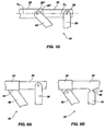
- a handle 40" of a syringe includes another embodiment of connection element 66". on central region 65" of first member 60" and another, corresponding embodiment of pivotal connection element 56" on central region 55" of second member 50".
- Connection element 66 which protrudes from central region 65" and is fixed in relation thereto, includes a cylindrical section 66a", a series of adjacent teeth 66b" protruding from at least a portion of the curved surface of cylindrical section 66a", and an enlarged retention head 66c" adjacent cylindrical section 66a", opposite from the remainder of first member 60".
- the distance that cylindrical section 66a" protrudes from central region 65" of first member 60" is preferably slightly larger than the thickness of second member 50".
- the corresponding pivotal connection element 56" of second member 50" comprises an elongated slot 56a" with a series of adjacent teeth 56b" protruding from at least a portion of an edge along the length of slot 56a".
- Teeth 56b" are configured and positioned complementarily to teeth 66b" of connection element 66" such that teeth 56b" and teeth 66b" cooperate by mutually engaging each other upon rotation of cylindrical section 66a" relative to slot 56a".
- the width of slot 56a" is preferably slightly larger than the diameter of cylindrical section 66a" of pivotal connection element 66" so as to substantially prevent side-to-side movement of pivotal connection element 66" relative to pivotal connection element 56".
- pivotal connection element 56" and 66" With respect to one another is substantially confined on the direction in which pivotal connection element 56" extends, which, as illustrated, is along the length of second handle 50".
- pivotal connection element 66" rotates relative to pivotal connection element 56" and moves downward through slot 56a" of pivotal connection element 56".
- pivotal connection element 66" rotates and moves in the opposite direction relative to pivotal connection element 56".
- handle 40 may additionally include a resilient element (e.g., a spring) may be associated with first and second members 60 and 50 ( e.g., at or near hinge element 70) in such a way as to force first and second members 60 and 50 apart from one another when they are not being held together.
- a resilient element e.g., a spring
- first and second members 60 and 50 e.g., at or near hinge element 70
- first and second members 60 and 50 When first and second members 60 and 50, or variations thereof, have been properly assembled with one another, it is preferred that practically any adult user be able to properly position their fingers on gripping end 62 and their thumb or palm against gripping end 52 while gripping ends 62 and 52 are spaced a maximum distance apart from one another with head 34 of plunger 30 located at distal end 21d of barrel 20.
- Plunger attachment end 58 includes ( e.g ., terminates at) a plunger connection element 59 that facilitates the pivotal connection of first member 50 to the corresponding handle connection element 38 of plunger 30.
- Plunger connection element 59 may comprise an aperture that is configured to receive hinge element 70.
- First member 50 and plunger 30 are pivotally connected to one another by positioning plunger attachment end 58 against the appropriate location of plunger 30 with plunger connection element 59 and aperture (not shown) of handle connection element 38 in alignment.
- a single hinge element 70 is then inserted through both plunger connection element 59 and the aperture of handle connection element 38.
- Hinge element 70 preferably includes an enlarged head 71 at each end thereof to maintain the assembled, pivotal relationship of plunger 30 and first member 50.
- other known types of pivotal connection arrangements between plunger 30 and first member 50 and their corresponding elements are also within the scope of the present invention.
- Second member 50 of handle 40 may be bent, or angled, to increase the leverage provided by first member 60 and the scissor-like arrangement of first member 60 and second member 50. As illustrated, second member 50 is bent at central region 55 thereof so that gripping end 52 of second member 50 extends away from first member 60. This configuration and arrangement provides further leverage, or mechanical advantage, when drawing plunger 30 proximally ( i.e., out of) barrel 20.
- first member 60 and second member 50 may include reinforcement ribs 72 or other reinforcement structures along at least a portion of the length thereof. As depicted, reinforcement ribs 72 are positioned along the edges of first member 60 and second member 50. Reinforcement ribs 72 may be positioned to prevent side-to-side bending of first member 60 or second member 50 during use of handle 40 to move plunger 30 relative to barrel 20.
- FIGs. 6A and 6B illustrate variations of syringe 10 ( FIG. 1 ), in which first member 60 and second member 50 of handle 40 are pivotally connected to one another, but at least one connection point between an end of a member 60, 50 of handle 40 and barrel 20 or plunger 30 does not pivot.
- a connection point 61 between an end of member 60 and barrel 20 does not pivot.
- a connection point 51 between an end of member 50 and plunger 30 does not pivot.
- connection points 61 and 51 do not pivot, the ends of members 60 and 50 may still be nonrigidly (e.g., flexibly) connected with barrel 20 and plunger 30, respectively ( e.g., by way of a flexible connecting material, an integral region of reduced thickness, etc.).
- at least one connection point 61, 51 may be substantially rigid.
- FIGs. 6A and 6B illustrate only a single non-pivoting connection point 61, 51, a syringe may include two non-pivoting connection points 61, 51.
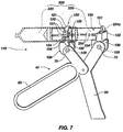
- Syringe 110 includes a scissor-grip handle 40, a barrel retaining member 120 pivotally secured to a first member 60 of handle 40, and a plunger biasing member 130 pivotally secured to a second member 50 of handle 40.
- Barrel retaining member 120 is configured to engage and retain at least a portion of the barrel 220 of a syringe 200.
- the depicted, exemplary embodiment of barrel retaining member 120 includes a flexible, elongate member 121 with a receptacle 124 at one end 122 thereof.
- Receptacle 124 is configured to receive the other end 123 of elongate member 121, as well as to facilitate the movement of a received portion of elongate member 121 therethrough.
- barrel retaining member 120 When receiving end 123 of elongate member 121 has been inserted into or through receptacle 124, barrel retaining member 120 takes on an annular configuration, forming a barrel receptacle 125 that may receive a portion of barrel 220 of syringe 200. As elongate member 121 moves through receptacle 124, the size of barrel receptacle 125 changes. The position of a portion of elongate member 121 extending through receptacle 124 may be maintained by way of a size adjustment member 126 (e.g., a screw, a spring-biased pin, etc.) that protrudes into receptacle 124 to engage the portion of elongate member 121 therein.
- a size adjustment member 126 e.g., a screw, a spring-biased pin, etc.
- Elongate member 121 may also include retention recesses 127 (e.g., grooves, slots, etc.) that are oriented along the length of elongate member 121 and that are configured to receive an interior end of size adjustment member 126 so as to further maintain the position of elongate member 121 relative to receptacle 124 and, thus, the size of barrel receptacle 125.
- retention recesses 127 e.g., grooves, slots, etc.
- Barrel retaining member 120 also includes a handle connection element 128 which extends from elongate member 121 and includes an aperture 129 therethrough. Aperture 129 is sized and configured to receive a hinge element 70 and, thus, to facilitate connection of a member of handle 40 to barrel retaining member 120.
- barrel retaining members which may be configured to receive a variety of different sizes of syringes or single syringe sizes, are also within the scope of the present invention.
- an exemplary embodiment of plunger biasing member 130 is configured to receive, retain, and apply force to a proximal end 231 p of a plunger 230 of syringe 200.
- the illustrated plunger biasing retaining member 130 includes a plunger receiving portion 131 that is configured to receive and apply pressure to proximal end 231p of plunger 230.
- plunger receiving portion 131 includes a receptacle 132 that is configured to receive at least a portion of the disk-shaped proximal end 231p of a conventionally configured syringe plunger 230.
- plunger biasing retaining member 130 includes a slot 134 that is continuous with receptacle 132 and that is positioned and sized to receive a portion of at least one of the support ribs 234 of a conventionally configured syringe plunger 230.
- proximal end 231p is substantially completely received within receptacle 132.
- slot 134 may include a narrow bottom section that receives a single, vertically oriented support rib 234 and a wider top section that receives opposed, horizontally oriented support ribs 234.
- a handle connection element 138 is positioned adjacent to (beneath) plunger receiving portion 131 and includes an aperture 139 that is configured to receive a portion of a hinge element 70 and to pivotally connect plunger biasing member 130 to first member 50 of handle 40.
- Handle 40 of syringe 110 may be configured as described previously herein.
- each of the elements of the syringe may be manufactured from any suitable material or materials, it is preferred that each of the elements of the syringe be formed by injection molding processes so as to afford low manufacturing cost and, consequently, to facilitate single-use, or disposability, of the syringe.
- polycarbonates such as LEXAN® , manufactured by General Electric, or MAKROLON®, manufactured by Miles Chemicals, may be used.
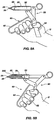
- FIGs. 8A and 8B an example of the use of an aspiration apparatus incorporating teachings of the present invention is illustrated.
- FIG. 8A illustrates an aspiration apparatus 10 in an initial position, in which a plunger 30 of a syringe is fully or almost fully disposed within receptacle 23 of barrel 20 and gripping ends 52 and 62 of handles 50 and 60 are positioned part from one another.
- plunger 30 is drawn distally through receptacle 23 of barrel 20, creating a vacuum therein that, in turn, draws fluid 300, tissues, or cells through either lumen 26 of syringe tip 25 ( FIGs. 1 and 2 ) or lumen 82 of aspiration port 80 ( FIG. 3 ) and into receptacle 23.
- Fluid 300 may then be removed from receptacle 23 of barrel 20 by moving gripping ends 52 and 62 of handles 50 and 60 apart from one another.
- handle 40 provides sufficient leverage that the force applied by a single hand of a user will be translated into an adequate amount of force upon plunger 30 and within receptacle 23 to force even relatively high viscosity fluids into receptacle 23.
- the configurations of members 50 and 60 of handle 40 facilitate gripping thereof with a single hand, the fine motor skills of which can be used in such a way as to precisely control the amount of fluid being introduced into or discharged from receptacle 23 of syringe barrel 20.
- Aspiration apparatus may be used in a variety of different procedures, including, without limitation, obtaining samples of bodily fluids (e.g., blood, blood clots, etc.) and cells or tissues (e.g., with a biopsy needle or other biopsy instrument).
- bodily fluids e.g., blood, blood clots, etc.
- cells or tissues e.g., with a biopsy needle or other biopsy instrument.
Landscapes
- Health & Medical Sciences (AREA)
- Life Sciences & Earth Sciences (AREA)
- Engineering & Computer Science (AREA)
- Heart & Thoracic Surgery (AREA)
- Public Health (AREA)
- Veterinary Medicine (AREA)
- Hematology (AREA)
- Biomedical Technology (AREA)
- Animal Behavior & Ethology (AREA)
- General Health & Medical Sciences (AREA)
- Surgery (AREA)
- Pathology (AREA)
- Medical Informatics (AREA)
- Molecular Biology (AREA)
- Physics & Mathematics (AREA)
- Biophysics (AREA)
- Manufacturing & Machinery (AREA)
- Vascular Medicine (AREA)
- Anesthesiology (AREA)
- Infusion, Injection, And Reservoir Apparatuses (AREA)
- External Artificial Organs (AREA)
- Measurement Of The Respiration, Hearing Ability, Form, And Blood Characteristics Of Living Organisms (AREA)
Applications Claiming Priority (2)
| Application Number | Priority Date | Filing Date | Title |
|---|---|---|---|
| US11/431,420 US7534234B2 (en) | 2006-05-09 | 2006-05-09 | Hand-held aspiration syringe and methods |
| PCT/US2007/011270 WO2007133615A2 (en) | 2006-05-09 | 2007-05-09 | Hand-held aspiration syringe and methods |
Publications (3)
| Publication Number | Publication Date |
|---|---|
| EP2032186A2 EP2032186A2 (en) | 2009-03-11 |
| EP2032186A4 EP2032186A4 (en) | 2014-03-26 |
| EP2032186B1 true EP2032186B1 (en) | 2021-01-20 |
Family
ID=38686052
Family Applications (1)
| Application Number | Title | Priority Date | Filing Date |
|---|---|---|---|
| EP07794711.7A Not-in-force EP2032186B1 (en) | 2006-05-09 | 2007-05-09 | Hand-held aspiration syringe and methods |
Country Status (4)
| Country | Link |
|---|---|
| US (4) | US7534234B2 (enExample) |
| EP (1) | EP2032186B1 (enExample) |
| JP (1) | JP2009536554A (enExample) |
| WO (1) | WO2007133615A2 (enExample) |
Families Citing this family (80)
| Publication number | Priority date | Publication date | Assignee | Title |
|---|---|---|---|---|
| US11337894B2 (en) * | 2018-06-15 | 2022-05-24 | James T. Doubet | Syringe adapter for animal medication |
| US11090444B2 (en) | 2018-06-15 | 2021-08-17 | James T. Doubet | Syringe adapter for medication |
| US11097058B2 (en) * | 2018-06-15 | 2021-08-24 | James T. Doubet | Syringe adapter for medication |
| US10709850B2 (en) | 2018-06-15 | 2020-07-14 | James T. Doubet | Syringe adapter for medication |
| US7041084B2 (en) | 2001-05-24 | 2006-05-09 | Fojtik Shawn P | Hand-held, hand operated power syringe and methods |
| WO2005094283A2 (en) | 2004-03-25 | 2005-10-13 | Hauser David L | Vascular filter device |
| US7534234B2 (en) * | 2006-05-09 | 2009-05-19 | Fojtik Shawn P | Hand-held aspiration syringe and methods |
| US10058656B2 (en) | 2006-10-24 | 2018-08-28 | Pmt Partners, Llc | Syringe with rotatable element, systems including the syringe, and associated methods |
| US7674247B2 (en) | 2006-10-24 | 2010-03-09 | Control Medical Technology, Llc | Double barrel syringe and handles for use with double barrel syringes |
| US20080098564A1 (en) * | 2006-10-24 | 2008-05-01 | Fojtik Shawn P | Locking Hinges for Syringe Handles, Syringes Including Locking Hinges, and Associated Methods |
| US8672893B2 (en) | 2007-10-23 | 2014-03-18 | Control Medical Technology, Llc | Syringe with rotatable element, aspiration systems including the syringe, and associated methods |
| US20090088702A1 (en) * | 2007-10-01 | 2009-04-02 | Fojtik Shawn P | Methods for manually injecting/aspirating fluids through small diameter catheters and needles and manual injection/aspiration systems including small diameter catheters and needles |
| US11191931B2 (en) | 2007-10-01 | 2021-12-07 | Pmt Partners, Llc | Methods for manually injecting/aspirating fluids through small diameter catheters and needles and manual injection/aspiration systems including small diameter catheters and needles |
| US20090275900A1 (en) * | 2008-04-02 | 2009-11-05 | Hetherington Hugh E | Syringe for injection control device |
| US20090254060A1 (en) * | 2008-04-02 | 2009-10-08 | Hetherington Hugh E | Motor assembly for injection control device |
| US20090306544A1 (en) * | 2008-06-09 | 2009-12-10 | Ho-Kin Ng | Instillation/aspiration device |
| US20090306545A1 (en) * | 2008-06-09 | 2009-12-10 | Mamdouh Elsakka | Bronchoalveolar lavage catheter assembly |
| US20090301480A1 (en) * | 2008-06-09 | 2009-12-10 | Mamdouh Elsakka | Diagnostic sample collection system and method of use |
| US8574167B2 (en) * | 2008-12-16 | 2013-11-05 | Devicor Medical Products, Inc. | Needle for biopsy device |
| US20100152610A1 (en) * | 2008-12-16 | 2010-06-17 | Parihar Shailendra K | Hand Actuated Tetherless Biopsy Device with Pistol Grip |
| US8162850B2 (en) * | 2008-12-16 | 2012-04-24 | Devicor Medical Products, Inc. | Hand actuated tetherless biopsy device with scissors grip |
| EP2273573A4 (en) | 2009-03-11 | 2012-11-14 | Panasonic Corp | NITRIDE SEMICONDUCTOR ELEMENT AND MANUFACTURING METHOD THEREFOR |
| JP2013501559A (ja) * | 2009-08-14 | 2013-01-17 | ビー イージー アイピー | 拡張器及び拡張器を備えたアッセンブリー |
| US8992482B2 (en) * | 2010-03-12 | 2015-03-31 | Control Medical Technology, Llc | Syringe with flow control valves and associated methods |
| JP4843123B2 (ja) | 2010-04-01 | 2011-12-21 | パナソニック株式会社 | 窒化物系半導体素子およびその製造方法 |
| CN102859724A (zh) | 2010-04-28 | 2013-01-02 | 松下电器产业株式会社 | 氮化物系半导体元件及其制造方法 |
| FI20106184A0 (fi) * | 2010-11-11 | 2010-11-11 | Thermo Fisher Scientific Oy | Kahvapipetti |
| US8986247B2 (en) | 2011-06-29 | 2015-03-24 | Stuart H. Miller | Insufflation pump |
| WO2013026043A1 (en) | 2011-08-18 | 2013-02-21 | Hologic, Inc. | Tissue removal system |
| US9067023B2 (en) | 2011-11-21 | 2015-06-30 | University Of Louisville Research Foundation, Inc. | Ergonomic syringe and adaptor |
| US20140291355A1 (en) * | 2011-11-22 | 2014-10-02 | Mallinckrodt Llc | Hand-Actuated Fluid Delivery Device |
| DK3821830T3 (da) | 2012-09-24 | 2024-11-11 | Inari Medical Inc | Anordning og fremgangsmåde til behandling af vaskulær okklusion |
| US8784434B2 (en) | 2012-11-20 | 2014-07-22 | Inceptus Medical, Inc. | Methods and apparatus for treating embolism |
| CA2931983C (en) | 2012-11-30 | 2021-12-07 | Magnolia Medical Technologies, Inc. | Syringe based fluid diversion mechanism for bodily-fluid sampling |
| US9688458B1 (en) * | 2013-05-31 | 2017-06-27 | Hasbro, Inc. | Folding portable craft gun with storage for plunger rod |
| WO2015002147A1 (ja) * | 2013-07-01 | 2015-01-08 | 三菱瓦斯化学株式会社 | オキシメチレン共重合体の製造方法 |
| WO2015061365A1 (en) | 2013-10-21 | 2015-04-30 | Inceptus Medical, Llc | Methods and apparatus for treating embolism |
| EP3094363A4 (en) | 2014-06-09 | 2017-10-04 | Inceptus Medical, LLC | Retraction and aspiration device for treating embolism and associated systems and methods |
| WO2016049607A1 (en) | 2014-09-25 | 2016-03-31 | Pmt Partners, Llc | Syringe with rotatable handle and associated systems and methods |
| ES2975734T3 (es) | 2015-01-29 | 2024-07-12 | Becton Dickinson Co | Catéter integrado de inserción rápida |
| DE102015102350B3 (de) | 2015-02-19 | 2016-05-04 | Sartorius Stedim Biotech Gmbh | Filtrationsvorrichtung für flüssige Proben |
| US10118024B2 (en) | 2015-02-19 | 2018-11-06 | Stuart H. Miller | Insufflation pump |
| US11234626B2 (en) * | 2015-06-12 | 2022-02-01 | Magnolia Medical Technologies, Inc. | Devices and methods for syringe-based fluid transfer for bodily-fluid sampling |
| US10702292B2 (en) | 2015-08-28 | 2020-07-07 | Incuvate, Llc | Aspiration monitoring system and method |
| US10342571B2 (en) | 2015-10-23 | 2019-07-09 | Inari Medical, Inc. | Intravascular treatment of vascular occlusion and associated devices, systems, and methods |
| CN113796927B (zh) | 2015-10-23 | 2025-03-04 | 伊纳里医疗公司 | 脉管闭塞的脉管内治疗以及相关的装置、系统和方法 |
| US9700332B2 (en) | 2015-10-23 | 2017-07-11 | Inari Medical, Inc. | Intravascular treatment of vascular occlusion and associated devices, systems, and methods |
| CN109069790A (zh) | 2015-12-18 | 2018-12-21 | 伊纳里医疗公司 | 导管轴及相关装置、系统和方法 |
| US10226263B2 (en) | 2015-12-23 | 2019-03-12 | Incuvate, Llc | Aspiration monitoring system and method |
| WO2018080590A1 (en) | 2016-10-24 | 2018-05-03 | Inari Medical | Devices and methods for treating vascular occlusion |
| US10912539B2 (en) * | 2017-02-07 | 2021-02-09 | New York University | Endoswab for sampling and culture in minimally invasive surgery |
| WO2018175792A1 (en) * | 2017-03-22 | 2018-09-27 | Matthew Feinsod | Syringe |
| PT3678731T (pt) | 2017-09-06 | 2024-12-10 | Inari Medical Inc | Válvulas de hemostase e métodos de utilização |
| ES2902942T3 (es) | 2017-10-05 | 2022-03-30 | Vladislav Alexandrovich Odintsov | Jeringa de aspiración |
| CN107796650B (zh) * | 2017-10-18 | 2019-09-24 | 宜昌市中心人民医院 | 一种病理科取样装置 |
| US11154314B2 (en) | 2018-01-26 | 2021-10-26 | Inari Medical, Inc. | Single insertion delivery system for treating embolism and associated systems and methods |
| USD890925S1 (en) | 2018-06-15 | 2020-07-21 | James T. Doubet | Syringe adapter for medication |
| US20190388625A1 (en) | 2018-06-15 | 2019-12-26 | James T. Doubet | Syringe adapter for medication |
| CN112867455B (zh) | 2018-08-13 | 2025-07-29 | 伊纳里医疗有限公司 | 治疗栓塞的系统和相关的装置和方法 |
| CN109512471B (zh) * | 2018-11-28 | 2021-08-06 | 陕西省肿瘤医院 | 一种骨髓活检穿刺取样装置 |
| CA3153525A1 (en) | 2019-09-24 | 2021-04-01 | Bard Access Systems, Inc. | An integrated acute central venous catheter and peripherally inserted venous catheter |
| US11864779B2 (en) | 2019-10-16 | 2024-01-09 | Inari Medical, Inc. | Systems, devices, and methods for treating vascular occlusions |
| CA3168492A1 (en) | 2020-01-23 | 2021-07-29 | Bard Access Systems, Inc. | Splitable catheter docking station system |
| WO2021158965A1 (en) | 2020-02-07 | 2021-08-12 | 2Mg, Inc. | Devices and methods for removal of material in a vasculature |
| AU2021259483B2 (en) | 2020-04-23 | 2025-10-02 | Bard Access Systems, Inc. | Rapidly insertable central catheters including catheter assemblies |
| KR20230013131A (ko) | 2020-05-21 | 2023-01-26 | 바드 액세스 시스템즈, 인크. | 카테터 어셈블리를 포함하는 신속 삽입 가능 중심 카테터 및 그 방법(rapidly insertable central catheters including catheter assemblies and methods thereof) |
| US12274836B2 (en) | 2020-06-29 | 2025-04-15 | Bard Access Systems, Inc. | Rapidly insertable central catheters including assemblies and methods thereof |
| US12161820B2 (en) | 2020-06-29 | 2024-12-10 | Bard Access Systems, Inc. | Rapidly insertable central catheters including catheter assemblies and methods thereof |
| US20230263962A1 (en) * | 2020-08-28 | 2023-08-24 | David F Dalury | Syringe-support apparatus and methods of use |
| AU2021371314B2 (en) | 2020-10-28 | 2025-09-25 | Bard Access Systems, Inc. | Catheter placement system with stiffening system |
| KR20230121775A (ko) | 2020-12-17 | 2023-08-21 | 바드 액세스 시스템즈, 인크. | 신속 삽입 가능 중심 카테터, 조립체, 및 그 방법(rapidlyinsertable central catheters, assemblies, and methods thereof) |
| AU2021409944B2 (en) | 2020-12-21 | 2025-10-02 | Bard Access Systems, Inc. | Fluid path optimization in catheter insertion systems |
| WO2022140429A1 (en) | 2020-12-21 | 2022-06-30 | Bard Access Systems, Inc. | Optimized structural support in catheter insertion systems |
| US20220211357A1 (en) * | 2021-01-05 | 2022-07-07 | Olympus Medical Systems Corporation | Systems and methods for performing tissue biopsy |
| US11696793B2 (en) | 2021-03-19 | 2023-07-11 | Crossfire Medical Inc | Vascular ablation |
| AU2023208030A1 (en) | 2022-01-11 | 2024-07-18 | Inari Medical, Inc. | Devices for removing clot material from intravascularly implanted devices, and associated systems and methods |
| US20240149020A1 (en) | 2022-11-04 | 2024-05-09 | Controlled Delivery Systems, Inc. | Catheters for the aspiration controlled delivery of closure agents |
| AU2023371657A1 (en) | 2022-11-04 | 2025-05-15 | Solvein Inc. | Catheters and related methods for aspiration and controlled delivery of closure agents |
| WO2025235015A1 (en) | 2024-05-10 | 2025-11-13 | Inari Medical, Inc. | Mechanical thrombectomy assemblies with relief features, and associated devices, systems, and methods |
| US12427267B1 (en) * | 2025-01-30 | 2025-09-30 | Sunil Sharma | Injector device |
Family Cites Families (37)
| Publication number | Priority date | Publication date | Assignee | Title |
|---|---|---|---|---|
| US4033346A (en) * | 1975-08-21 | 1977-07-05 | N. J. Phillips Pty. Limited | Adjustment device for drench guns or syringes |
| US4067334A (en) * | 1976-10-29 | 1978-01-10 | Haller J Gilbert | Self-injecting hypodermic syringe device |
| US4364388A (en) * | 1981-04-20 | 1982-12-21 | Cech Jerry E | Syringe dispensing apparatus |
| US4632669A (en) * | 1984-05-07 | 1986-12-30 | Plastic Specialties, Inc. | Pressure indicating medical injection gun |
| US4594073A (en) * | 1984-10-31 | 1986-06-10 | Stine Charles R | Aspiration syringe holder |
| US4581021A (en) * | 1985-01-28 | 1986-04-08 | Ergomed | Squeeze-actuated syringe |
| US4632869A (en) * | 1985-09-03 | 1986-12-30 | Mobil Oil Corporation | Resin composition, opaque film and method of preparing same |
| US4737151A (en) * | 1986-07-25 | 1988-04-12 | Clement John G | Syringe injector |
| US4715378A (en) * | 1986-07-28 | 1987-12-29 | Mansfield Scientific, Inc. | Balloon catheter |
| US4832692A (en) * | 1986-10-14 | 1989-05-23 | Cordis Corporation | Inflation syringe assembly for percutaneous transluminal angioplasty |
| US4968303A (en) * | 1988-09-27 | 1990-11-06 | Eli Lilly And Company | Hypodermic syringe holder |
| GB9024916D0 (en) * | 1990-11-16 | 1991-01-02 | Du Pont Canada | Improved pouch dispenser |
| US5115816A (en) * | 1991-01-24 | 1992-05-26 | Peter F. Lee, Inc. | Single-hand controlled fine needle aspiration device |
| IL102941A0 (en) * | 1991-08-27 | 1993-01-31 | Thomas R Johnson | Injection syringe |
| DE9200521U1 (de) * | 1991-11-12 | 1993-03-25 | Thera Patent GmbH & Co KG Gesellschaft für industrielle Schutzrechte, 8031 Seefeld | Behälter für fließfähige Substanzen |
| US5213110A (en) * | 1992-03-16 | 1993-05-25 | Du-Kedem Projects Ltd. | Pistol-grip vacuum soft tissue biopsy device |
| US5336201A (en) * | 1992-06-29 | 1994-08-09 | Baxter International Inc. | Syringe driving apparatus |
| US5439131A (en) * | 1992-09-25 | 1995-08-08 | Tokuyama Corporation | Assembly including container, closure and operating means |
| US5288285A (en) * | 1993-02-16 | 1994-02-22 | Carter Wade P | Holder for filling syringe with radioactive liquid |
| US5306147A (en) * | 1993-06-28 | 1994-04-26 | Dragan William B | Dental syringe and cartridge therefor |
| US5560373A (en) * | 1994-04-11 | 1996-10-01 | De Santis; Stephen A. | Needle core biopsy instrument with durable or disposable cannula assembly |
| US5511556A (en) * | 1994-04-11 | 1996-04-30 | Desantis; Stephen A. | Needle core biopsy instrument |
| US5507727A (en) * | 1994-08-02 | 1996-04-16 | Design Standards Corporation | Inflation deflation syringe assembly for use in angioplasty procedures |
| US5514071A (en) * | 1994-10-06 | 1996-05-07 | Sielaff, Jr.; Carl F. | Remote injection device |
| US5569208A (en) * | 1995-08-01 | 1996-10-29 | Merit Medical Systems, Inc. | System for managing delivery of contrast media |
| US5964736A (en) | 1995-09-22 | 1999-10-12 | Lane; Donovan R. | Livestock biological and vaccine handling system |
| US5733258A (en) * | 1995-09-22 | 1998-03-31 | Lane; Donovan R. | Livestock biological and vaccine handling system to include pistol grip syringe and cartridge |
| US6030368A (en) * | 1996-09-20 | 2000-02-29 | Azam Anwar | Power syringe having a base and a lever |
| DE29700656U1 (de) * | 1997-01-15 | 1997-03-27 | Henke-Sass, Wolf GmbH, 78532 Tuttlingen | Veterinärspritze mit Dosiereinrichtung |
| CA2241615A1 (en) * | 1997-06-26 | 1998-12-26 | An-Go-Gen Inc. | Catheters |
| US5968017A (en) * | 1997-10-14 | 1999-10-19 | Merit Medical Systems, Inc. | Pulse fluid infusion systems |
| US5951517A (en) * | 1997-10-14 | 1999-09-14 | Merit Medical Systems, Inc. | One-hand pulse pump |
| US6059759A (en) * | 1997-10-14 | 2000-05-09 | Merit Medical Systems, Inc. | Infusion catheter systems with tactile sensing feedback |
| US6346085B1 (en) * | 2000-06-27 | 2002-02-12 | Noah I. Schiffman | Soft tissue biopsy instrument |
| US7041084B2 (en) * | 2001-05-24 | 2006-05-09 | Fojtik Shawn P | Hand-held, hand operated power syringe and methods |
| US20050085769A1 (en) * | 2001-07-17 | 2005-04-21 | Kerberos Proximal Solutions | Fluid exchange system for controlled and localized irrigation and aspiration |
| US7534234B2 (en) | 2006-05-09 | 2009-05-19 | Fojtik Shawn P | Hand-held aspiration syringe and methods |
-
2006
- 2006-05-09 US US11/431,420 patent/US7534234B2/en active Active
-
2007
- 2007-05-09 JP JP2009509849A patent/JP2009536554A/ja active Pending
- 2007-05-09 WO PCT/US2007/011270 patent/WO2007133615A2/en not_active Ceased
- 2007-05-09 EP EP07794711.7A patent/EP2032186B1/en not_active Not-in-force
-
2009
- 2009-05-19 US US12/468,729 patent/US7976511B2/en not_active Expired - Fee Related
-
2011
- 2011-07-12 US US13/181,398 patent/US8491539B2/en not_active Expired - Fee Related
-
2013
- 2013-07-23 US US13/948,770 patent/US20140005634A1/en not_active Abandoned
Non-Patent Citations (1)
| Title |
|---|
| None * |
Also Published As
| Publication number | Publication date |
|---|---|
| WO2007133615B1 (en) | 2008-11-13 |
| US7976511B2 (en) | 2011-07-12 |
| US20120022404A1 (en) | 2012-01-26 |
| US8491539B2 (en) | 2013-07-23 |
| US7534234B2 (en) | 2009-05-19 |
| EP2032186A2 (en) | 2009-03-11 |
| US20070265573A1 (en) | 2007-11-15 |
| JP2009536554A (ja) | 2009-10-15 |
| WO2007133615A3 (en) | 2008-09-25 |
| US20090227894A1 (en) | 2009-09-10 |
| WO2007133615A2 (en) | 2007-11-22 |
| EP2032186A4 (en) | 2014-03-26 |
| US20140005634A1 (en) | 2014-01-02 |
Similar Documents
| Publication | Publication Date | Title |
|---|---|---|
| EP2032186B1 (en) | Hand-held aspiration syringe and methods | |
| US7988677B2 (en) | Hand-held, hand-operated power syringe and methods | |
| US11191931B2 (en) | Methods for manually injecting/aspirating fluids through small diameter catheters and needles and manual injection/aspiration systems including small diameter catheters and needles | |
| EP4188219B1 (en) | Aspiration syringes | |
| CN108883225B (zh) | 通过放置的外周静脉注射导管进行流体输送的装置和方法 | |
| EP3691719B1 (en) | Aspiration syringe | |
| WO2009045393A1 (en) | Methods for manually injecting/aspirating fluids through small diameter catheters and needles and manual injection/aspiration systems including small diameter catheters and needles | |
| CN104684607A (zh) | 流体转移装置 | |
| US20230050769A1 (en) | Syringe for improved injection and aspiration | |
| EP1304128A1 (en) | Valve disc and combination filling device using the valve disc, and tube, pipe jointing device, connection port manufacturing device, and pipe jointing system | |
| US11167091B2 (en) | Precision syringe | |
| EP0474218A1 (en) | Medical paste syringe, filling method and paste injecting device | |
| WO2017191609A1 (en) | Enhanced suction device for surgical operation | |
| JPH0928809A (ja) | 血管穿刺装置 | |
| RU177324U1 (ru) | Аспирационный шприц | |
| RU2677356C1 (ru) | Шприц для аспирации |
Legal Events
| Date | Code | Title | Description |
|---|---|---|---|
| PUAI | Public reference made under article 153(3) epc to a published international application that has entered the european phase |
Free format text: ORIGINAL CODE: 0009012 |
|
| 17P | Request for examination filed |
Effective date: 20081201 |
|
| AK | Designated contracting states |
Kind code of ref document: A2 Designated state(s): AT BE BG CH CY CZ DE DK EE ES FI FR GB GR HU IE IS IT LI LT LU LV MC MT NL PL PT RO SE SI SK TR |
|
| AX | Request for extension of the european patent |
Extension state: AL BA HR MK RS |
|
| DAX | Request for extension of the european patent (deleted) | ||
| A4 | Supplementary search report drawn up and despatched |
Effective date: 20140226 |
|
| RIC1 | Information provided on ipc code assigned before grant |
Ipc: A61B 5/15 20060101ALI20140220BHEP Ipc: A61M 1/00 20060101ALI20140220BHEP Ipc: A61M 5/31 20060101ALI20140220BHEP Ipc: A61M 5/315 20060101ALI20140220BHEP Ipc: A61M 5/00 20060101AFI20140220BHEP Ipc: A61M 5/20 20060101ALI20140220BHEP Ipc: A61B 10/00 20060101ALI20140220BHEP Ipc: A61B 5/153 20060101ALI20140220BHEP |
|
| STAA | Information on the status of an ep patent application or granted ep patent |
Free format text: STATUS: EXAMINATION IS IN PROGRESS |
|
| 17Q | First examination report despatched |
Effective date: 20171212 |
|
| GRAP | Despatch of communication of intention to grant a patent |
Free format text: ORIGINAL CODE: EPIDOSNIGR1 |
|
| STAA | Information on the status of an ep patent application or granted ep patent |
Free format text: STATUS: GRANT OF PATENT IS INTENDED |
|
| INTG | Intention to grant announced |
Effective date: 20200720 |
|
| GRAS | Grant fee paid |
Free format text: ORIGINAL CODE: EPIDOSNIGR3 |
|
| GRAA | (expected) grant |
Free format text: ORIGINAL CODE: 0009210 |
|
| STAA | Information on the status of an ep patent application or granted ep patent |
Free format text: STATUS: THE PATENT HAS BEEN GRANTED |
|
| AK | Designated contracting states |
Kind code of ref document: B1 Designated state(s): AT BE BG CH CY CZ DE DK EE ES FI FR GB GR HU IE IS IT LI LT LU LV MC MT NL PL PT RO SE SI SK TR |
|
| REG | Reference to a national code |
Ref country code: GB Ref legal event code: FG4D |
|
| REG | Reference to a national code |
Ref country code: CH Ref legal event code: EP |
|
| REG | Reference to a national code |
Ref country code: DE Ref legal event code: R096 Ref document number: 602007060913 Country of ref document: DE |
|
| REG | Reference to a national code |
Ref country code: AT Ref legal event code: REF Ref document number: 1360109 Country of ref document: AT Kind code of ref document: T Effective date: 20210215 |
|
| REG | Reference to a national code |
Ref country code: IE Ref legal event code: FG4D |
|
| REG | Reference to a national code |
Ref country code: NL Ref legal event code: MP Effective date: 20210120 |
|
| REG | Reference to a national code |
Ref country code: LT Ref legal event code: MG9D |
|
| REG | Reference to a national code |
Ref country code: AT Ref legal event code: MK05 Ref document number: 1360109 Country of ref document: AT Kind code of ref document: T Effective date: 20210120 |
|
| PG25 | Lapsed in a contracting state [announced via postgrant information from national office to epo] |
Ref country code: BG Free format text: LAPSE BECAUSE OF FAILURE TO SUBMIT A TRANSLATION OF THE DESCRIPTION OR TO PAY THE FEE WITHIN THE PRESCRIBED TIME-LIMIT Effective date: 20210420 Ref country code: NL Free format text: LAPSE BECAUSE OF FAILURE TO SUBMIT A TRANSLATION OF THE DESCRIPTION OR TO PAY THE FEE WITHIN THE PRESCRIBED TIME-LIMIT Effective date: 20210120 Ref country code: PT Free format text: LAPSE BECAUSE OF FAILURE TO SUBMIT A TRANSLATION OF THE DESCRIPTION OR TO PAY THE FEE WITHIN THE PRESCRIBED TIME-LIMIT Effective date: 20210520 Ref country code: GR Free format text: LAPSE BECAUSE OF FAILURE TO SUBMIT A TRANSLATION OF THE DESCRIPTION OR TO PAY THE FEE WITHIN THE PRESCRIBED TIME-LIMIT Effective date: 20210421 Ref country code: FI Free format text: LAPSE BECAUSE OF FAILURE TO SUBMIT A TRANSLATION OF THE DESCRIPTION OR TO PAY THE FEE WITHIN THE PRESCRIBED TIME-LIMIT Effective date: 20210120 Ref country code: LT Free format text: LAPSE BECAUSE OF FAILURE TO SUBMIT A TRANSLATION OF THE DESCRIPTION OR TO PAY THE FEE WITHIN THE PRESCRIBED TIME-LIMIT Effective date: 20210120 |
|
| PG25 | Lapsed in a contracting state [announced via postgrant information from national office to epo] |
Ref country code: SE Free format text: LAPSE BECAUSE OF FAILURE TO SUBMIT A TRANSLATION OF THE DESCRIPTION OR TO PAY THE FEE WITHIN THE PRESCRIBED TIME-LIMIT Effective date: 20210120 Ref country code: AT Free format text: LAPSE BECAUSE OF FAILURE TO SUBMIT A TRANSLATION OF THE DESCRIPTION OR TO PAY THE FEE WITHIN THE PRESCRIBED TIME-LIMIT Effective date: 20210120 Ref country code: PL Free format text: LAPSE BECAUSE OF FAILURE TO SUBMIT A TRANSLATION OF THE DESCRIPTION OR TO PAY THE FEE WITHIN THE PRESCRIBED TIME-LIMIT Effective date: 20210120 Ref country code: LV Free format text: LAPSE BECAUSE OF FAILURE TO SUBMIT A TRANSLATION OF THE DESCRIPTION OR TO PAY THE FEE WITHIN THE PRESCRIBED TIME-LIMIT Effective date: 20210120 |
|
| PG25 | Lapsed in a contracting state [announced via postgrant information from national office to epo] |
Ref country code: IS Free format text: LAPSE BECAUSE OF FAILURE TO SUBMIT A TRANSLATION OF THE DESCRIPTION OR TO PAY THE FEE WITHIN THE PRESCRIBED TIME-LIMIT Effective date: 20210520 |
|
| REG | Reference to a national code |
Ref country code: DE Ref legal event code: R097 Ref document number: 602007060913 Country of ref document: DE |
|
| PG25 | Lapsed in a contracting state [announced via postgrant information from national office to epo] |
Ref country code: EE Free format text: LAPSE BECAUSE OF FAILURE TO SUBMIT A TRANSLATION OF THE DESCRIPTION OR TO PAY THE FEE WITHIN THE PRESCRIBED TIME-LIMIT Effective date: 20210120 Ref country code: CZ Free format text: LAPSE BECAUSE OF FAILURE TO SUBMIT A TRANSLATION OF THE DESCRIPTION OR TO PAY THE FEE WITHIN THE PRESCRIBED TIME-LIMIT Effective date: 20210120 |
|
| PLBE | No opposition filed within time limit |
Free format text: ORIGINAL CODE: 0009261 |
|
| STAA | Information on the status of an ep patent application or granted ep patent |
Free format text: STATUS: NO OPPOSITION FILED WITHIN TIME LIMIT |
|
| PG25 | Lapsed in a contracting state [announced via postgrant information from national office to epo] |
Ref country code: RO Free format text: LAPSE BECAUSE OF FAILURE TO SUBMIT A TRANSLATION OF THE DESCRIPTION OR TO PAY THE FEE WITHIN THE PRESCRIBED TIME-LIMIT Effective date: 20210120 Ref country code: SK Free format text: LAPSE BECAUSE OF FAILURE TO SUBMIT A TRANSLATION OF THE DESCRIPTION OR TO PAY THE FEE WITHIN THE PRESCRIBED TIME-LIMIT Effective date: 20210120 Ref country code: DK Free format text: LAPSE BECAUSE OF FAILURE TO SUBMIT A TRANSLATION OF THE DESCRIPTION OR TO PAY THE FEE WITHIN THE PRESCRIBED TIME-LIMIT Effective date: 20210120 Ref country code: ES Free format text: LAPSE BECAUSE OF FAILURE TO SUBMIT A TRANSLATION OF THE DESCRIPTION OR TO PAY THE FEE WITHIN THE PRESCRIBED TIME-LIMIT Effective date: 20210120 |
|
| REG | Reference to a national code |
Ref country code: DE Ref legal event code: R119 Ref document number: 602007060913 Country of ref document: DE |
|
| 26N | No opposition filed |
Effective date: 20211021 |
|
| REG | Reference to a national code |
Ref country code: CH Ref legal event code: PL |
|
| GBPC | Gb: european patent ceased through non-payment of renewal fee |
Effective date: 20210509 |
|
| PG25 | Lapsed in a contracting state [announced via postgrant information from national office to epo] |
Ref country code: LI Free format text: LAPSE BECAUSE OF NON-PAYMENT OF DUE FEES Effective date: 20210531 Ref country code: LU Free format text: LAPSE BECAUSE OF NON-PAYMENT OF DUE FEES Effective date: 20210509 Ref country code: MC Free format text: LAPSE BECAUSE OF FAILURE TO SUBMIT A TRANSLATION OF THE DESCRIPTION OR TO PAY THE FEE WITHIN THE PRESCRIBED TIME-LIMIT Effective date: 20210120 Ref country code: CH Free format text: LAPSE BECAUSE OF NON-PAYMENT OF DUE FEES Effective date: 20210531 |
|
| REG | Reference to a national code |
Ref country code: BE Ref legal event code: MM Effective date: 20210531 |
|
| PG25 | Lapsed in a contracting state [announced via postgrant information from national office to epo] |
Ref country code: SI Free format text: LAPSE BECAUSE OF FAILURE TO SUBMIT A TRANSLATION OF THE DESCRIPTION OR TO PAY THE FEE WITHIN THE PRESCRIBED TIME-LIMIT Effective date: 20210120 |
|
| PG25 | Lapsed in a contracting state [announced via postgrant information from national office to epo] |
Ref country code: IT Free format text: LAPSE BECAUSE OF FAILURE TO SUBMIT A TRANSLATION OF THE DESCRIPTION OR TO PAY THE FEE WITHIN THE PRESCRIBED TIME-LIMIT Effective date: 20210120 Ref country code: IE Free format text: LAPSE BECAUSE OF NON-PAYMENT OF DUE FEES Effective date: 20210509 Ref country code: GB Free format text: LAPSE BECAUSE OF NON-PAYMENT OF DUE FEES Effective date: 20210509 Ref country code: DE Free format text: LAPSE BECAUSE OF NON-PAYMENT OF DUE FEES Effective date: 20211201 |
|
| PG25 | Lapsed in a contracting state [announced via postgrant information from national office to epo] |
Ref country code: IS Free format text: LAPSE BECAUSE OF FAILURE TO SUBMIT A TRANSLATION OF THE DESCRIPTION OR TO PAY THE FEE WITHIN THE PRESCRIBED TIME-LIMIT Effective date: 20210520 Ref country code: FR Free format text: LAPSE BECAUSE OF NON-PAYMENT OF DUE FEES Effective date: 20210531 |
|
| PG25 | Lapsed in a contracting state [announced via postgrant information from national office to epo] |
Ref country code: BE Free format text: LAPSE BECAUSE OF NON-PAYMENT OF DUE FEES Effective date: 20210531 |
|
| PG25 | Lapsed in a contracting state [announced via postgrant information from national office to epo] |
Ref country code: HU Free format text: LAPSE BECAUSE OF FAILURE TO SUBMIT A TRANSLATION OF THE DESCRIPTION OR TO PAY THE FEE WITHIN THE PRESCRIBED TIME-LIMIT; INVALID AB INITIO Effective date: 20070509 Ref country code: CY Free format text: LAPSE BECAUSE OF FAILURE TO SUBMIT A TRANSLATION OF THE DESCRIPTION OR TO PAY THE FEE WITHIN THE PRESCRIBED TIME-LIMIT Effective date: 20210120 |
|
| PG25 | Lapsed in a contracting state [announced via postgrant information from national office to epo] |
Ref country code: TR Free format text: LAPSE BECAUSE OF FAILURE TO SUBMIT A TRANSLATION OF THE DESCRIPTION OR TO PAY THE FEE WITHIN THE PRESCRIBED TIME-LIMIT Effective date: 20210120 |
|
| PG25 | Lapsed in a contracting state [announced via postgrant information from national office to epo] |
Ref country code: MT Free format text: LAPSE BECAUSE OF FAILURE TO SUBMIT A TRANSLATION OF THE DESCRIPTION OR TO PAY THE FEE WITHIN THE PRESCRIBED TIME-LIMIT Effective date: 20210120 |