EP2031325A2 - Accumulator, in particular for an air conditioning system, with dirt catcher - Google Patents
Accumulator, in particular for an air conditioning system, with dirt catcher Download PDFInfo
- Publication number
- EP2031325A2 EP2031325A2 EP20080011669 EP08011669A EP2031325A2 EP 2031325 A2 EP2031325 A2 EP 2031325A2 EP 20080011669 EP20080011669 EP 20080011669 EP 08011669 A EP08011669 A EP 08011669A EP 2031325 A2 EP2031325 A2 EP 2031325A2
- Authority
- EP
- European Patent Office
- Prior art keywords
- housing
- accumulator
- region
- trough
- accumulator according
- Prior art date
- Legal status (The legal status is an assumption and is not a legal conclusion. Google has not performed a legal analysis and makes no representation as to the accuracy of the status listed.)
- Withdrawn
Links
Images


Classifications
-
- F—MECHANICAL ENGINEERING; LIGHTING; HEATING; WEAPONS; BLASTING
- F25—REFRIGERATION OR COOLING; COMBINED HEATING AND REFRIGERATION SYSTEMS; HEAT PUMP SYSTEMS; MANUFACTURE OR STORAGE OF ICE; LIQUEFACTION SOLIDIFICATION OF GASES
- F25B—REFRIGERATION MACHINES, PLANTS OR SYSTEMS; COMBINED HEATING AND REFRIGERATION SYSTEMS; HEAT PUMP SYSTEMS
- F25B43/00—Arrangements for separating or purifying gases or liquids; Arrangements for vaporising the residuum of liquid refrigerant, e.g. by heat
- F25B43/006—Accumulators
-
- F—MECHANICAL ENGINEERING; LIGHTING; HEATING; WEAPONS; BLASTING
- F25—REFRIGERATION OR COOLING; COMBINED HEATING AND REFRIGERATION SYSTEMS; HEAT PUMP SYSTEMS; MANUFACTURE OR STORAGE OF ICE; LIQUEFACTION SOLIDIFICATION OF GASES
- F25B—REFRIGERATION MACHINES, PLANTS OR SYSTEMS; COMBINED HEATING AND REFRIGERATION SYSTEMS; HEAT PUMP SYSTEMS
- F25B2500/00—Problems to be solved
- F25B2500/01—Geometry problems, e.g. for reducing size
-
- F—MECHANICAL ENGINEERING; LIGHTING; HEATING; WEAPONS; BLASTING
- F25—REFRIGERATION OR COOLING; COMBINED HEATING AND REFRIGERATION SYSTEMS; HEAT PUMP SYSTEMS; MANUFACTURE OR STORAGE OF ICE; LIQUEFACTION SOLIDIFICATION OF GASES
- F25B—REFRIGERATION MACHINES, PLANTS OR SYSTEMS; COMBINED HEATING AND REFRIGERATION SYSTEMS; HEAT PUMP SYSTEMS
- F25B43/00—Arrangements for separating or purifying gases or liquids; Arrangements for vaporising the residuum of liquid refrigerant, e.g. by heat
- F25B43/02—Arrangements for separating or purifying gases or liquids; Arrangements for vaporising the residuum of liquid refrigerant, e.g. by heat for separating lubricants from the refrigerant
Definitions
- the invention relates to an accumulator, in particular for an air conditioner, with strainer according to the preamble of claim 1.
- This accumulator has a housing, a flow path for a refrigerant with an inlet pipe, which is the input side connected to a refrigerant supply line and the output side opens to the housing interior, a U-shaped curved outlet pipe, the input side to the housing interior open and output side with a refrigerant drain line is connectable, a housed inside the housing desiccant.
- the flow path communicates via a passage opening with a lower region of the housing interior.
- a sieve which is supported by a portafilter.
- the portafilter has a positioning element for aligning the screen with respect to the passage opening and a holding device, so that the portafilter for mounting on the outlet tube can be plugged onto the outlet tube from outside.
- the screen is designed as a flat screen fabric, and the portafilter has support bars for supporting the screen surface.
- the housing is cylindrical, wherein it has a cylindrical peripheral wall and a slightly outwardly turned bottom wall, which is flat in the region of the portafilter. At the top, a lid with an inlet and an outlet is provided. The attachment of such a battery is carried out by means of a holder.
- Another, generic accumulator is from the WO 98/10854 A1 known.
- the housing is formed with a cylindrical peripheral wall and an outwardly turned bottom.
- no separately formed lid is provided, but also the upper portion formed everted outwards, wherein openings are provided for the supply and discharge.
- a passage opening in the U-tube for the oil is provided at the lowest point of the U-tube, with a sieve being attached to the U-tube by means of a holding device in front of it so that a certain distance remains between the base and the sieve. The attachment of such a battery is carried out by means of a holder.
- the US 4,651,540 A discloses an accumulator having a multi-part construction, consisting of a cover, a cylindrical peripheral wall and a separately formed therefrom, inverted bottom, wherein in the lowermost region an outwardly projecting threaded pin for mounting the accumulator is provided.
- a comparable housing structure of a rechargeable battery is also known from the US 5,076,071 A known.
- the US 5,660,058 A discloses an accumulator with a U-tube, at the bottom of an opening with upstream filter is described.
- the accumulator has a cylindrical, approximately centrally divided thermoformed housing with a constant wall thickness, wherein in the lowermost region - offset by a kind of step - a trough-like depression is formed into which the filter protrudes, the passage area completely within the tub is located close to the ground.
- the arrangement of the opening very far down ensures that sufficient oil that collects in the lowest part of the accumulator, is taken along by the U-tube flowing gaseous refrigerant, so that a sufficient lubrication, in particular of the compressor can be ensured.
- dirt accumulates in the bottom area of the accumulator, which can lead to problems.
- an accumulator in particular for an air conditioner, comprising a housing with a lid, wherein in the bottom region of the housing, a trough for collecting the oil contained in the refrigerant and dirt particles is formed, which has a cross section which is smaller than the cross section in is arranged above the region of the housing of the accumulator, wherein the transition to the trough is formed like a step, a flow path for a refrigerant with an inlet, which is the input side with a refrigerant supply line connectable and the output side opens to the housing interior, a U-shaped curved outlet pipe, which is on the input side to the housing interior open and output side connectable to a refrigerant discharge line, wherein the flow path is connected via a passage opening with a lower portion of the housing interior, and in front of the passage opening an oil filter is arranged, wherein the oil filter is arranged at least with a substantial portion of its passage area above the trough.
- the well formed in the bottom portion of the housing serves, in particular, to collect the oil which separates from the (liquid) refrigerant and to absorb dirt, among other things from the dirt retained by the oil filter.
- the oil filter is arranged with a substantial portion of its passage area relatively high above the lowest surface of the accumulator, a sufficient space for receiving dirt particles is present. Complete clogging of the filter by the soil collecting dirt can be safely avoided, so that always enough oil passes through the passage surface to the through hole of the U-tube and the lubrication function is ensured.
- the passage opening (or possibly also passage openings) in front of which the oil filter is arranged is preferably arranged in the lower, curved region of the U-shaped outlet pipe in the uppermost region or above the trough, so that a distance of approximately between the lower surface of the housing the tub depth or more than the tub depth is formed. This provides a sufficiently large collecting space for dirt particles.
- the filter surrounds the U-tube, for which purpose it is preferably clipped to the U-tube.
- the passage area for the oil ie the area in which the filter material is provided and oil can flow, preferably extends over a substantial area of the circumference of the U-tube, ie over preferably at least 50%, in particular at least 60%, 70% or more preferably at least 80% of the circumference.
- the filter is formed like a ring.
- the housing is preferably formed integrally by means of extrusion.
- extrusion i. a pressure forming method according to DIN 8583
- the available space can be optimized, especially in the bottom area of the accumulator, the space can be optimally designed and thus used optimally.
- the housing of the accumulator is preferably made of aluminum, in particular aluminum of the groups Al 3xxx, Al 5xxx or Al 6xxx. These materials can be well formed by extrusion molding and are also suitable as a housing for a rechargeable battery.
- the housing is provided on the outside in the bottom region with a positioning structure that differs at least partially from the cylindrical shape.
- the positioning structure is preferably formed by a three, four, five, six, seven or octagon, more preferably by a hexagon or octagon.
- the provision of a positioning structure which differs at least in a region from the cylindrical shape makes possible a simple, exact positioning, also with regard to the orientation in the circumferential direction.
- the accumulator can also be handled easier when torques, for example.
- the tightening torque during assembly of the accumulator occur because, for example, a hexagon, can serve as a means for capturing torque forces.
- the accumulator can be installed without a holder provided on the circumference with a corresponding configuration of a recording. A simple inclusion in a tree module for the positioning structure is sufficient.
- the trough in the bottom region of the housing preferably extends at least partially into a positioning structure formed on the outside, ie a partial region of the positioning structure is hollow on the inside, so that material and weight can be saved. Also can be saved by the optimized use of space height.
- the minimum material thickness in the central longitudinal axis of the housing preferably corresponds at most to twice the wall thickness in the peripheral wall region of the housing, more preferably at most one and a half times the wall thickness, and most preferably at most the simple wall thickness in the peripheral wall region of the housing.
- an oil filter is preferably provided in front of the passage opening and at least one coarse filter for large dirt particles above the oil filter. So coarse impurities can be removed before the actual oil filter and collected in an area above the bottom area. This prevents or reduces at least a significant change in the level of the stored oil volume by accumulating dirt in the course of operation of the accumulator.
- the coarse filter is preferably formed by a sheet provided with a plurality of through holes, however, for example, a coarse mesh or woven fabric or other suitable means for coarse particle deposition is also suitable.
- the coarse filter is used in addition to the separation of coarse particles and the calming of the oil and possibly existing liquid refrigerant below the coarse filter, so that even finer dirt particles settle on the floor.
- particles are deposited which are finer than the mesh size of the oil filter, so that the compressor is additionally at least partially protected against the finest particles.
- Such an accumulator is preferably arranged in a refrigerant circuit, in particular an automotive air conditioning system.
- An accumulator 1 as used for example for motor vehicle air conditioning systems, has a housing 2 with a separately formed, fixed from above on the housing 2 lid 3.
- the housing 2 has a substantially cylindrical peripheral wall 4 and a bottom region 5, the structure of which will be discussed in more detail below.
- the bottom region 5 begins substantially without transition from the peripheral wall 4 with a first curvature 6, in which region the wall thickness substantially corresponds to the wall thickness of the peripheral wall 4, ie is constant.
- a second curvature 7 follows in the opposite direction.
- the curvature 7 merges in a radius 8 into a surface 9 extending radially to the central longitudinal axis of the housing 2, the region formed by the curvature 7, the radius 8 and the surface 9 forming a trough 10 in the bottom region 5 form.
- the curvature 7 merges into a hexagon 11, which is parallel to the central longitudinal axis of the housing 2 extending surfaces and in the radial direction to the central longitudinal axis of the housing 2 extending end surface 12 has.
- the minimum material thickness which is arranged in the region between the surface 9 and the end surface 12, about the wall thickness of the peripheral wall 4. Due to the hexagon 11 and the trough 10 material accumulations are substantially only in the region of the edge outer sides of the hexagon eleventh intended.
- the hexagon 11 here forms a positioning structure, with the aid of which the accumulator 1 can be used here in a front module made of plastic with a hexagon socket as a receptacle, so that the accumulator 1 is mounted rotatably and torque-safe, and provided on the cover terminals 20 are secured.
- the accumulator 1 has said connections 20 and 27 provided on its cover, which are connected to the supply and discharge line (not shown) for the refrigerant.
- the continuation of the supply line ends in the uppermost region of the accumulator 1.
- the discharge is connected to the U-tube 21 with different lengths of legs, via which gaseous refrigerant is sucked out of the interior.
- a desiccant is arranged in a receptacle 22 in the present case.
- This receptacle 22 is seated on a provided with a plurality of holes plate 23, which serves as a coarse filter for itself accumulating in the lower region of the accumulator 1 dirt. Further, the sheet 23 serves for flow calming and prevents vibration noises which may be generated by the suction pipe.
- an oil filter 24 is arranged in the bent part of the U-tube 21 in front of a downwardly disposed passage opening (not shown in detail), here clipped onto the U-tube 21 by means of a clip connection (see Fig. 4 ).
- the network structure of the oil filter 24, which forms a passage surface for the oil (and possibly refrigerant), is not shown in the drawing, but extends as shown Fig. 4 can be seen, substantially around the entire circumference of the U-tube 21.
- a cover 25 is provided with an annular gap in the upper region.
- a further filter 26 is further arranged in the region of the inflow opening in the U-tube 21, through which the gaseous refrigerant is sucked into the U-tube 21.
- the lower portion of the oil filter 24 is disposed within the trough 10, wherein it does not abut the surface 9, so that between oil filter 24 and surface 9, a relatively large gap for receiving (fine) dirt is formed, and the dirt the filter is not blocked.
- a substantial region of the oil filter 24, in particular a substantial region of the passage surface, is arranged above the trough 10.
- the passage opening in the U-tube 21 is disposed within the oil filter 24 just above the trough 10.
- the accumulator 1 acts as follows: The coming of the evaporator refrigerant, which contains both a liquid phase and a gaseous phase, is supplied to the interior of the housing 2 via the inlet 20 connected to the port. It is distributed in the interior, wherein the liquid phase with the oil contained therein separates from the gaseous phase, moves downwards and flows through the annular gap, past the plate 25 in the direction of the bottom region 5. The oil contained in the refrigerant continues to sink due to its greater specific gravity down and forms an oil layer in the bottom region 5, which in certain operating conditions extends beyond the passage opening, ie the trough 10 completely fills.
- the liquid phase is freed from the moisture contained in it by the desiccant.
- the gaseous phase of the refrigerant is sucked in the upper region, below the plate 25 in the U-tube 21, flows through this and leaves the accumulator 1 through the outlet, where the drain line is connected to the corresponding port 20 of the lid 3.
- the accumulating in the bottom region 5 oil, which has already passed the coarse screen, by the oil filter 24 also smaller impurities, such as. Finished due to manufacturing in the refrigerant circuit chips, freed, which fall after switching off the air conditioning cycle on the bottom of the tub and there collect. By passing past the passage opening gaseous phase, the oil that passes from below through the passage opening in the U-tube, entrained, so that it is fed back to the compressor.
Abstract
Description
Die Erfindung betrifft einen Akkumulator, insbesondere für eine Klimaanlage, mit Schmutzfänger gemäß dem Oberbegriff des Anspruchs 1.The invention relates to an accumulator, in particular for an air conditioner, with strainer according to the preamble of
Aus der
Ein anderer, gattungsgemäßer Akkumulator ist aus der
Die
Die
Derartige Akkumulatoren lassen somit noch Wünsche offen.Such accumulators leave nothing to be desired.
Ausgehend von diesem Stand der Technik ist es Aufgabe der Erfindung, einen verbesserten Akkumulator zur Verfügung zu stellen.Based on this prior art, it is an object of the invention to provide an improved accumulator available.
Diese Aufgabe wird gelöst durch einen Akkumulator mit den Merkmalen des Anspruchs 1. Vorteilhafte Ausgestaltungen sind Gegenstand der Unteransprüche.This object is achieved by an accumulator with the features of
Erfindungsgemäß ist ein Akkumulator, insbesondere für eine Klimaanlage, vorgesehen, aufweisend ein Gehäuse mit einem Deckel, wobei im Bodenbereich des Gehäuses eine Wanne zum Sammeln des im Kältemittel enthaltenen Öls und von Schmutzpartikeln ausgebildet ist, die einen Querschnitt aufweist, der kleiner als der Querschnitt im oberhalb angeordneten Bereich des Gehäuses des Akkumulators ist, wobei der Übergang zur Wanne stufenartig ausgebildet ist, einen Strömungsweg für ein Kältemittel mit einem Eintritt, welcher eingangsseitig mit einer Kältemittel-Zulaufleitung verbindbar ist und sich ausgangsseitig zum Gehäuseinneren öffnet, einem U-förmig gekrümmten Auslassrohr, welches eingangsseitig zum Gehäuseinneren offen und ausgangsseitig mit einer Kältemittel-Ablaufleitung verbindbar ist, wobei der Strömungsweg über eine Durchgangsöffnung mit einem unteren Bereich des Gehäuseinneren verbunden ist, und vor der Durchgangsöffnung ein Ölfilter angeordnet ist, wobei das Ölfilter zumindest mit einem wesentlichen Bereich seiner Durchtrittsfläche oberhalb der Wanne angeordnet ist. Die im Bodenbereich des Gehäuses ausgebildete Wanne dient insbesondere dem Sammeln des Öls, das sich vom (flüssigen) Kältemittel trennt und zur Aufnahme von Schmutz, unter anderem vom Schmutz, der vom Ölfilter zurückgehalten wird. Dadurch, dass das Ölfilter mit einem wesentlichen Bereich seiner Durchtrittsfläche relativ hoch über der untersten Fläche des Akkumulators angeordnet ist, ist ein ausreichender Raum zur Aufnahme von Schmutzpartikeln vorhanden. Ein vollständiges Zusetzen des Filters durch den sich am Boden sammelnden Schmutz kann sicher vermieden werden, so dass stets ausreichend Öl durch die Durchtrittsfläche zur Durchgangsöffnung des U-Rohres gelangt und die Schmierfunktion sichergestellt ist.According to the invention an accumulator, in particular for an air conditioner, is provided, comprising a housing with a lid, wherein in the bottom region of the housing, a trough for collecting the oil contained in the refrigerant and dirt particles is formed, which has a cross section which is smaller than the cross section in is arranged above the region of the housing of the accumulator, wherein the transition to the trough is formed like a step, a flow path for a refrigerant with an inlet, which is the input side with a refrigerant supply line connectable and the output side opens to the housing interior, a U-shaped curved outlet pipe, which is on the input side to the housing interior open and output side connectable to a refrigerant discharge line, wherein the flow path is connected via a passage opening with a lower portion of the housing interior, and in front of the passage opening an oil filter is arranged, wherein the oil filter is arranged at least with a substantial portion of its passage area above the trough. The well formed in the bottom portion of the housing serves, in particular, to collect the oil which separates from the (liquid) refrigerant and to absorb dirt, among other things from the dirt retained by the oil filter. Characterized in that the oil filter is arranged with a substantial portion of its passage area relatively high above the lowest surface of the accumulator, a sufficient space for receiving dirt particles is present. Complete clogging of the filter by the soil collecting dirt can be safely avoided, so that always enough oil passes through the passage surface to the through hole of the U-tube and the lubrication function is ensured.
Die Durchgangsöffnung (oder ggf. auch Durchgangsöffnungen) vor der das Ölfilter angeordnet ist, ist vorzugsweise im unteren, gekrümmten Bereich des U-förmigen Auslassrohres im obersten Bereich oder oberhalb der Wanne angeordnet ist, so dass zwischen der unteren Fläche des Gehäuses ein Abstand von annährend der Wannentiefe oder mehr als der Wannnentiefe ausgebildet ist. Dies stellt einen ausreichend großen Sammelraum für Schmutzpartikel zur Verfügung.The passage opening (or possibly also passage openings) in front of which the oil filter is arranged is preferably arranged in the lower, curved region of the U-shaped outlet pipe in the uppermost region or above the trough, so that a distance of approximately between the lower surface of the housing the tub depth or more than the tub depth is formed. This provides a sufficiently large collecting space for dirt particles.
Besonders bevorzugt umgibt das Filter das U-Rohr, wofür es vorzugsweise am U-Rohr angeclipst ist. Die Durchtrittsfläche für das Öl, d.h. die Fläche, in dem das Filtermaterial vorgesehen und für Öl durchströmbar ist, erstreckt sich bevorzugt über einen wesentlichen Bereich des Umfangs des U-Rohres, d.h. über vorzugsweise mindestens 50%, insbesondere mindestens 60%, 70% oder besonders bevorzugt mindestens 80% des Umfanges. Besonders bevorzugt ist das Filter ringartig ausgebildet.Particularly preferably, the filter surrounds the U-tube, for which purpose it is preferably clipped to the U-tube. The passage area for the oil, ie the area in which the filter material is provided and oil can flow, preferably extends over a substantial area of the circumference of the U-tube, ie over preferably at least 50%, in particular at least 60%, 70% or more preferably at least 80% of the circumference. Particularly preferably, the filter is formed like a ring.
Das Gehäuse ist vorzugsweise einstückig mittels Fließpressens ausgebildet. Durch eine Herstellung mittels Fließpressens, d.h. eines Druckumformverfahrens gemäß DIN 8583, im Unterschied zu üblichen Herstellungsverfahren der Gehäuse, kann der vorhandene Bauraum optimiert werden, insbesondere im Bodenbereich des Akkumulators kann der Raum optimal ausgestaltet und somit auch optimal genutzt werden. Das Gehäuse des Akkumulators ist vorzugsweise aus Aluminium, insbesondere aus Aluminium der Gruppen Al 3xxx, Al 5xxx oder Al 6xxx, gefertigt. Diese Materialien lassen sich gut mittels Fließpressens umformen und sind zudem als Gehäuse für einen Akkumulator geeignet.The housing is preferably formed integrally by means of extrusion. By production by extrusion, i. a pressure forming method according to DIN 8583, in contrast to conventional production methods of the housing, the available space can be optimized, especially in the bottom area of the accumulator, the space can be optimally designed and thus used optimally. The housing of the accumulator is preferably made of aluminum, in particular aluminum of the groups Al 3xxx, Al 5xxx or Al 6xxx. These materials can be well formed by extrusion molding and are also suitable as a housing for a rechargeable battery.
Insbesondere bevorzugt ist das Gehäuse außenseitig im Bodenbereich mit einer Positionierungsstruktur versehen, die sich zumindest bereichsweise von der Zylinderform unterscheidet. Die Positionierungsstruktur wird bevorzugt durch einen Drei-, Vier, Fünf-, Sechs-, Sieben- oder Achtkant gebildet, insbesondere bevorzugt durch einen Sechs- oder Achtkant. Das Vorsehen einer sich zumindest in einem Bereich von der Zylinderform unterscheidenden Positionierungsstruktur ermöglicht ein einfaches, exaktes Positionieren, auch in Bezug auf die Ausrichtung in Umfangsrichtung. Der Akkumulator kann zudem einfacher gehandhabt werden, wenn Drehmomente, bspw. das Anzugsdrehmoment bei der Montage des Akkumulators, auftreten, da bspw. ein Sechskant, als Mittel zum Auffangen von Drehmomentenkräften dienen kann. Ferner kann der Akkumulator ohne einen am Umfang vorgesehenen Halter bei entsprechender Ausgestaltung einer Aufnahme eingebaut werden. Eine einfache Aufnahme in einem Baumodul für die Positionierungsstruktur ist ausreichend.Particularly preferably, the housing is provided on the outside in the bottom region with a positioning structure that differs at least partially from the cylindrical shape. The positioning structure is preferably formed by a three, four, five, six, seven or octagon, more preferably by a hexagon or octagon. The provision of a positioning structure which differs at least in a region from the cylindrical shape makes possible a simple, exact positioning, also with regard to the orientation in the circumferential direction. The accumulator can also be handled easier when torques, for example. The tightening torque during assembly of the accumulator, occur because, for example, a hexagon, can serve as a means for capturing torque forces. Furthermore, the accumulator can be installed without a holder provided on the circumference with a corresponding configuration of a recording. A simple inclusion in a tree module for the positioning structure is sufficient.
Die Wanne im Bodenbereich des Gehäuses erstreckt sich vorzugsweise zumindest teilweise bis in eine außenseitig ausgebildete Positionierungsstruktur, d.h. ein Teilbereich der Positionierungsstruktur ist innen hohl ausgebildet, so dass Material und Gewicht eingespart werden kann. Ebenfalls kann durch die optimierte Raumausnutzung Bauhöhe eingespart werden.The trough in the bottom region of the housing preferably extends at least partially into a positioning structure formed on the outside, ie a partial region of the positioning structure is hollow on the inside, so that material and weight can be saved. Also can be saved by the optimized use of space height.
Die minimale Materialstärke in der Mittellängsachse des Gehäuses entspricht vorzugsweise maximal der doppelten Wandstärke im Umfangswandbereich des Gehäuses, besonders bevorzugt maximal der eineinhalbfachen Wandstärke, und ganz besonders bevorzugt maximal der einfachen Wandstärke im Umfangswandbereich des Gehäuses.The minimum material thickness in the central longitudinal axis of the housing preferably corresponds at most to twice the wall thickness in the peripheral wall region of the housing, more preferably at most one and a half times the wall thickness, and most preferably at most the simple wall thickness in the peripheral wall region of the housing.
Im Inneren des Gehäuses ist vorzugsweise vor der Durchgangsöffnung ein Ölfilter und oberhalb des Ölfilters mindestens ein Grobfilter für große Schmutzpartikel vorgesehen. So können grobe Verunreinigungen bereits vor dem eigentlichen Ölfilter entfernt und in einem Bereich oberhalb des Bodenbereichs gesammelt werden. Dies Verhindert oder verringert zumindest eine wesentliche Veränderung des Pegelstands des gespeicherten Ölvolumens durch sich sammelnden Schmutz im Laufe des Betriebs des Akkumulators.Inside the housing, an oil filter is preferably provided in front of the passage opening and at least one coarse filter for large dirt particles above the oil filter. So coarse impurities can be removed before the actual oil filter and collected in an area above the bottom area. This prevents or reduces at least a significant change in the level of the stored oil volume by accumulating dirt in the course of operation of the accumulator.
Das Grobfilter ist vorzugsweise durch ein mit einer Mehrzahl von Durchgangsöffnungen versehenes Blech gebildet, jedoch ist bspw. ein grobmaschiges Netz oder Gewebe oder ein geeignetes anderes Mittel zur Abscheidung von Grobpartikeln ebenso geeignet. Das Grobfilter dient neben der Abscheidung von Grobpartikeln auch der Beruhigung des Öls und des ggf. vorhandenen flüssigen Kältemittels unterhalb des Grobfilters, so dass sich auch feinere Schmutzpartikel am Boden absetzen. Gegebenenfalls setzen sich in Folge der geringen Strömung auch Partikel ab, die feiner als die Maschenweite des Ölfilters sind, so dass der Kompressor zusätzlich zumindest teilweise vor Feinstpartikeln geschützt wird.The coarse filter is preferably formed by a sheet provided with a plurality of through holes, however, for example, a coarse mesh or woven fabric or other suitable means for coarse particle deposition is also suitable. The coarse filter is used in addition to the separation of coarse particles and the calming of the oil and possibly existing liquid refrigerant below the coarse filter, so that even finer dirt particles settle on the floor. Optionally, as a result of the low flow, particles are deposited which are finer than the mesh size of the oil filter, so that the compressor is additionally at least partially protected against the finest particles.
Ein derartiger Akkumulator wird vorzugsweise in einem Kältemittel-Kreislauf, insbesondere einer Kraftfahrzeug-Klimaanlage, angeordnet.Such an accumulator is preferably arranged in a refrigerant circuit, in particular an automotive air conditioning system.
Im Folgenden wird die vorliegende Erfindung anhand eines Ausführungsbeispiels unter Bezugnahme auf die Zeichnung näher erläutert. Es zeigen:
- Fig. 1
- eine aufgeschnittene Ansicht eines erfindungsgemäßen Akkumulators,
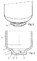
- Fig. 2
- eine perspektivische Ansicht des Bodenbereichs des Akkumulators von
Fig. 1 , - Fig. 3
- eine geschnittene Darstellung des untersten Bereichs des Gehäuses ohne Einbauten, und
- Fig. 4
- eine perspektivische Darstellung des untersten Bereichs des U-Rohres mit Ölfilter.
- Fig. 1
- a cutaway view of an accumulator according to the invention,
- Fig. 2
- a perspective view of the bottom portion of the accumulator of
Fig. 1 . - Fig. 3
- a sectional view of the lowermost portion of the housing without internals, and
- Fig. 4
- a perspective view of the lowermost portion of the U-pipe with oil filter.
Ein Akkumulator 1, wie er beispielsweise für Kraftfahrzeug-Klimaanlagen verwendet wird, weist ein Gehäuse 2 mit einem getrennt ausgebildeten, fest von oben her auf das Gehäuse 2 aufgesetzten Deckel 3 auf. Das Gehäuse 2 weist eine im Wesentlichen zylindrische Umfangswand 4 und einen Bodenbereich 5 auf, auf dessen Struktur im Folgenden näher eingegangen wird.An
Der Bodenbereich 5 fängt im Wesentlichen übergangslos von der Umfangswand 4 mit einer ersten Krümmung 6 an, wobei in diesem Bereich die Wandstärke im Wesentlichen der Wandstärke der Umfangswand 4 entspricht, d.h. konstant ist. Direkt anschließend an die Krümmung 6 folgt eine zweite Krümmung 7 in entgegengesetzter Richtung. Auf Seite der Innenfläche des Bodenbereichs 5 geht die Krümmung 7 in einem Radius 8 in eine sich radialer zur Mittellängsachse des Gehäuses 2 erstreckende Fläche 9 über, wobei der durch die Krümmung 7, den Radius 8 und die Fläche 9 gebildete Bereich eine Wanne 10 im Bodenbereich 5 bilden. Außenseitig geht die Krümmung 7 in einen Sechskant 11 über, der sich parallel zur Mittellängsachse des Gehäuses 2 erstreckende Flächen und eine sich in radialer Richtung zur Mittellängsachse des Gehäuses 2 erstreckende Endfläche 12 aufweist. Hierbei entspricht die minimale Materialstärke, die im Bereich zwischen der Fläche 9 und der Endfläche 12 angeordnet ist, etwa der Wandstärke der Umfangswand 4. In Folge des Sechskants 11 und der Wanne 10 sind Materialanhäufungen im Wesentlichen nur im Bereich der Kantenau-ßenseiten des Sechskants 11 vorgesehen.The
Der Sechskant 11 bildet hierbei eine Positionierungsstruktur, mit deren Hilfe der Akkumulator 1 vorliegend in ein Frontmodul aus Kunststoff mit einem Innensechskant als Aufnahme eingesetzt werden kann, so dass der Akkumulator 1 dreh- und momentensicher gelagert ist, und am Deckel vorgesehenen Anschlüsse 20 gesichert sind. Zudem lassen sich die gebogenen Rohre der Zu- und Ableitung, die an den Anschlüssen 20 angebracht werden, einfacher an den Flanschen montieren, da der Sechskant 11 ein Mittel zur einfacheren Einleitung eines Moments (oder Gegenmoments) im Rahmen der Montage bildet.The
Der Akkumulator 1 weist besagte, an seinem Deckel vorgesehene Anschlüsse 20 und 27 auf, die mit der Zu- bzw. Ableitung (nicht dargestellt) für das Kältemittel verbunden werden. Die Weiterführung der Zuleitung endet im obersten Bereich des Akkumulators 1. Die Ableitung ist mit U-Rohr 21 mit unterschiedlich langen Schenkeln verbunden, über welches gasförmiges Kältemittel aus dem Innenraum abgesaugt wird. Zwischen den Schenkeln des U-Rohrs 21 ist vorliegend ein Trockenmittel in einer Aufnahme 22 angeordnet. Diese Aufnahme 22 sitzt auf einem mit einer Mehrzahl von Löchern versehenen Blech 23, welches als Grobfilter für sich im unteren Bereich des Akkumulators 1 ansammelnden Schmutz dient. Ferner dient das Blech 23 der Strömungsberuhigung und verhindert Schwingungsgeräusche, die durch das Saugrohr entstehen können.The
Unterhalb dieses Blechs 23 ist im gebogenen Teil des U-Rohres 21 vor einer unten angeordneten Durchgangsöffnung (nicht näher dargestellt) ein Ölfilter 24 angeordnet, vorliegend auf das U-Rohr 21 mit Hilfe einer Clipsverbindung geclipst (siehe
Wie aus
Der Akkumulator 1 wirkt folgendermaßen: Das vom Verdampfer kommende Kältemittel, welches sowohl eine flüssige Phase als auch eine gasförmige Phase enthält, wird dem Innenraum des Gehäuses 2 über den mit dem Anschluss 20 verbundenen Einlass zugeführt. Es verteilt sich im Innenraum, wobei die flüssige Phase mit dem hierin enthaltenen Öl sich von der gasförmigen Phase trennt, sich nach unten bewegt und durch den Ringspalt, vorbei am Blech 25 in Richtung Bodenbereich 5 strömt. Das im Kältemittel enthaltene Öl sinkt in Folge seines größeren spezifischen Gewichts weiter nach unten und bildet im Bodenbereich 5 eine Ölschicht, die in bestimmten Betriebszuständen bis über die Durchgangsöffnung reicht, d.h. die Wanne 10 vollständig ausfüllt.The
Die flüssige Phase wird durch das Trockenmittel von der in ihm enthaltenen Feuchtigkeit befreit. Die gasförmige Phase des Kältemittels wird im oberen Bereich, unterhalb des Blechs 25 in das U-Rohr 21 gesaugt, durchströmt dieses und verlässt den Akkumulator 1 durch den Auslass, wo die Ablaufleitung mit dem entsprechenden Anschluss 20 des Deckels 3 verbunden ist.The liquid phase is freed from the moisture contained in it by the desiccant. The gaseous phase of the refrigerant is sucked in the upper region, below the
Das sich im Bodenbereich 5 sammelnde Öl, welches bereits das Grobsieb passiert hat, wird durch den Ölfilter 24 auch von kleineren Verunreinigungen, wie bspw. feinen fertigungsbedingt in den Kältemittelkreislauf gelangten Spänen, befreit, die nach Ausschalten des Klimakreislaufs auf den Wannenboden absinken und sich dort sammeln. Durch die an der Durchgangsöffnung vorbeiströmende gasförmige Phase wird das Öl, das von unten durch die Durchgangsöffnung in das U-Rohr gelangt, mitgerissen, so dass es dem Verdichter wieder zugeführt wird.The accumulating in the
Claims (14)
Applications Claiming Priority (1)
| Application Number | Priority Date | Filing Date | Title |
|---|---|---|---|
| DE102007033149A DE102007033149A1 (en) | 2007-07-13 | 2007-07-13 | Accumulator, in particular for an air conditioning system, with dirt trap |
Publications (1)
| Publication Number | Publication Date |
|---|---|
| EP2031325A2 true EP2031325A2 (en) | 2009-03-04 |
Family
ID=40121565
Family Applications (1)
| Application Number | Title | Priority Date | Filing Date |
|---|---|---|---|
| EP20080011669 Withdrawn EP2031325A2 (en) | 2007-07-13 | 2008-06-27 | Accumulator, in particular for an air conditioning system, with dirt catcher |
Country Status (2)
| Country | Link |
|---|---|
| EP (1) | EP2031325A2 (en) |
| DE (1) | DE102007033149A1 (en) |
Cited By (1)
| Publication number | Priority date | Publication date | Assignee | Title |
|---|---|---|---|---|
| WO2019107011A1 (en) * | 2017-12-01 | 2019-06-06 | 株式会社不二工機 | Accumulator |
Citations (5)
| Publication number | Priority date | Publication date | Assignee | Title |
|---|---|---|---|---|
| US4651540A (en) | 1986-03-21 | 1987-03-24 | Tecumseh Products Company | Suction accumulator including an entrance baffle |
| US5076071A (en) | 1990-05-08 | 1991-12-31 | Tecumseh Products Company | Suction accumulator with dirt trap and filter |
| US5660058A (en) | 1995-11-03 | 1997-08-26 | Ford Motor Company | Accumulator for vehicle air conditioning system |
| WO1998010854A1 (en) | 1996-09-16 | 1998-03-19 | Denolf Stephen J | Accumulator oil filter/orifice having an extended tube |
| EP1176374B1 (en) | 2000-07-28 | 2005-11-02 | Hansa Metallwerke Ag | Accumulator for an air conditioner of the orifice type, particularly for vehicle air conditioners |
Family Cites Families (5)
| Publication number | Priority date | Publication date | Assignee | Title |
|---|---|---|---|---|
| US4474035A (en) * | 1983-12-23 | 1984-10-02 | Ford Motor Company | Domed accumulator for automotive air conditioning system |
| US5746065A (en) * | 1996-08-21 | 1998-05-05 | Automotive Fluid Systems, Inc. | Accumulator deflector connection and method |
| IT1312193B1 (en) * | 1999-04-20 | 2002-04-09 | Bundy Kmp S R L | DEHYDRATOR ACCUMULATOR FOR REFRIGERATION CIRCUITS AND ASSEMBLY PROCEDURE |
| ITMI20010655U1 (en) * | 2001-12-14 | 2003-06-16 | Ti Automotive Cisliano S R L | DEHYDRATOR ACCUMULATOR FOR REFRIGERATION CIRCUITS WITH SIMPLIFIED STRUCTURE |
| EP1775530B1 (en) * | 2005-10-12 | 2007-12-12 | COEXAL GmbH | Method for producing a device for collecting and drying a refrigerant in an air conditioning unit |
-
2007
- 2007-07-13 DE DE102007033149A patent/DE102007033149A1/en not_active Withdrawn
-
2008
- 2008-06-27 EP EP20080011669 patent/EP2031325A2/en not_active Withdrawn
Patent Citations (5)
| Publication number | Priority date | Publication date | Assignee | Title |
|---|---|---|---|---|
| US4651540A (en) | 1986-03-21 | 1987-03-24 | Tecumseh Products Company | Suction accumulator including an entrance baffle |
| US5076071A (en) | 1990-05-08 | 1991-12-31 | Tecumseh Products Company | Suction accumulator with dirt trap and filter |
| US5660058A (en) | 1995-11-03 | 1997-08-26 | Ford Motor Company | Accumulator for vehicle air conditioning system |
| WO1998010854A1 (en) | 1996-09-16 | 1998-03-19 | Denolf Stephen J | Accumulator oil filter/orifice having an extended tube |
| EP1176374B1 (en) | 2000-07-28 | 2005-11-02 | Hansa Metallwerke Ag | Accumulator for an air conditioner of the orifice type, particularly for vehicle air conditioners |
Cited By (1)
| Publication number | Priority date | Publication date | Assignee | Title |
|---|---|---|---|---|
| WO2019107011A1 (en) * | 2017-12-01 | 2019-06-06 | 株式会社不二工機 | Accumulator |
Also Published As
| Publication number | Publication date |
|---|---|
| DE102007033149A1 (en) | 2009-01-15 |
Similar Documents
| Publication | Publication Date | Title |
|---|---|---|
| EP1080298B2 (en) | Oil separator for removing oil from the crankcase ventilation gases of an internal combustion engine | |
| EP2052136B1 (en) | Device for seperating liquids from gases | |
| DE10200673B4 (en) | Automotive air filter | |
| EP2357430B1 (en) | Condenser for an air conditioner, in particular for a motor vehicle | |
| EP2145099B1 (en) | Fuel supply device, particularly for an internal combustion engine | |
| EP2788612B1 (en) | Fuel filter of an internal combustion engine and filter element of a fuel filter | |
| EP2129445A1 (en) | Filter for cleaning a fluid | |
| EP2881156B1 (en) | Filter element having a bypass channel and filter assembly with a filter element | |
| EP2602473A2 (en) | Fuel filter of an internal combustion engine and filter element of a fuel filter | |
| EP2579958B1 (en) | Filter device, in particular liquid filter | |
| WO2008084098A1 (en) | Fuel filter | |
| EP2984421B1 (en) | Receiver | |
| EP3067102B1 (en) | Water separator and water separation system with integrated water discharge device | |
| EP2031325A2 (en) | Accumulator, in particular for an air conditioning system, with dirt catcher | |
| DE102005024158C5 (en) | Dryer for a cooling medium in a cooling medium circuit, in particular for an air conditioning system of a vehicle | |
| WO2002042697A1 (en) | Collector for the liquid phase of a working medium of an air conditioning system | |
| DE202009001159U1 (en) | oil separator | |
| DE102005024167B4 (en) | Dryer for a cooling medium in a cooling medium circuit, in particular for an air conditioning system of a vehicle | |
| DE112017007736T5 (en) | Separator and oil-separating air filter device with such a separator and method for separating fluid from a gas stream originating from a connecting device | |
| DE112017007737T5 (en) | Separator and oil-separating air filter device with such a separator and method for separating fluid from a gas stream originating from a connecting device | |
| EP1361401B1 (en) | Filter drier cartridge | |
| DE102007028591A1 (en) | Accumulator, particularly for motor vehicle air conditioning system, has surface provided to surround end of pipe by which gas-shaped cooling unit is arrived in pipe | |
| DE102012015043B3 (en) | Air suction device for internal combustion engine of e.g. lorry, has vertical line section formed modular from suction pipes, which fluidically run in parallel and are fluidically connected with inlet- and/or outlet-side ends | |
| DE102016120477A1 (en) | Air dryer cartridge | |
| AT501181B1 (en) | Crankcase ventilation system, comprises pre-cleaning device and main oil separator made all of a piece |
Legal Events
| Date | Code | Title | Description |
|---|---|---|---|
| PUAI | Public reference made under article 153(3) epc to a published international application that has entered the european phase |
Free format text: ORIGINAL CODE: 0009012 |
|
| AK | Designated contracting states |
Kind code of ref document: A2 Designated state(s): AT BE BG CH CY CZ DE DK EE ES FI FR GB GR HR HU IE IS IT LI LT LU LV MC MT NL NO PL PT RO SE SI SK TR |
|
| AX | Request for extension of the european patent |
Extension state: AL BA MK RS |
|
| STAA | Information on the status of an ep patent application or granted ep patent |
Free format text: STATUS: THE APPLICATION IS DEEMED TO BE WITHDRAWN |
|
| 18D | Application deemed to be withdrawn |
Effective date: 20110104 |