EP2881156B1 - Filter element having a bypass channel and filter assembly with a filter element - Google Patents
Filter element having a bypass channel and filter assembly with a filter element Download PDFInfo
- Publication number
- EP2881156B1 EP2881156B1 EP14176671.7A EP14176671A EP2881156B1 EP 2881156 B1 EP2881156 B1 EP 2881156B1 EP 14176671 A EP14176671 A EP 14176671A EP 2881156 B1 EP2881156 B1 EP 2881156B1
- Authority
- EP
- European Patent Office
- Prior art keywords
- filter element
- filter
- end plate
- support tube
- liquid medium
- Prior art date
- Legal status (The legal status is an assumption and is not a legal conclusion. Google has not performed a legal analysis and makes no representation as to the accuracy of the status listed.)
- Active
Links
Images
Classifications
-
- F—MECHANICAL ENGINEERING; LIGHTING; HEATING; WEAPONS; BLASTING
- F01—MACHINES OR ENGINES IN GENERAL; ENGINE PLANTS IN GENERAL; STEAM ENGINES
- F01M—LUBRICATING OF MACHINES OR ENGINES IN GENERAL; LUBRICATING INTERNAL COMBUSTION ENGINES; CRANKCASE VENTILATING
- F01M11/00—Component parts, details or accessories, not provided for in, or of interest apart from, groups F01M1/00 - F01M9/00
- F01M11/03—Mounting or connecting of lubricant purifying means relative to the machine or engine; Details of lubricant purifying means
-
- B—PERFORMING OPERATIONS; TRANSPORTING
- B01—PHYSICAL OR CHEMICAL PROCESSES OR APPARATUS IN GENERAL
- B01D—SEPARATION
- B01D35/00—Filtering devices having features not specifically covered by groups B01D24/00 - B01D33/00, or for applications not specifically covered by groups B01D24/00 - B01D33/00; Auxiliary devices for filtration; Filter housing constructions
- B01D35/14—Safety devices specially adapted for filtration; Devices for indicating clogging
- B01D35/147—Bypass or safety valves
-
- B—PERFORMING OPERATIONS; TRANSPORTING
- B01—PHYSICAL OR CHEMICAL PROCESSES OR APPARATUS IN GENERAL
- B01D—SEPARATION
- B01D29/00—Filters with filtering elements stationary during filtration, e.g. pressure or suction filters, not covered by groups B01D24/00 - B01D27/00; Filtering elements therefor
- B01D29/11—Filters with filtering elements stationary during filtration, e.g. pressure or suction filters, not covered by groups B01D24/00 - B01D27/00; Filtering elements therefor with bag, cage, hose, tube, sleeve or like filtering elements
- B01D29/13—Supported filter elements
- B01D29/15—Supported filter elements arranged for inward flow filtration
- B01D29/21—Supported filter elements arranged for inward flow filtration with corrugated, folded or wound sheets
-
- B—PERFORMING OPERATIONS; TRANSPORTING
- B01—PHYSICAL OR CHEMICAL PROCESSES OR APPARATUS IN GENERAL
- B01D—SEPARATION
- B01D29/00—Filters with filtering elements stationary during filtration, e.g. pressure or suction filters, not covered by groups B01D24/00 - B01D27/00; Filtering elements therefor
- B01D29/50—Filters with filtering elements stationary during filtration, e.g. pressure or suction filters, not covered by groups B01D24/00 - B01D27/00; Filtering elements therefor with multiple filtering elements, characterised by their mutual disposition
- B01D29/52—Filters with filtering elements stationary during filtration, e.g. pressure or suction filters, not covered by groups B01D24/00 - B01D27/00; Filtering elements therefor with multiple filtering elements, characterised by their mutual disposition in parallel connection
- B01D29/54—Filters with filtering elements stationary during filtration, e.g. pressure or suction filters, not covered by groups B01D24/00 - B01D27/00; Filtering elements therefor with multiple filtering elements, characterised by their mutual disposition in parallel connection arranged concentrically or coaxially
-
- F—MECHANICAL ENGINEERING; LIGHTING; HEATING; WEAPONS; BLASTING
- F01—MACHINES OR ENGINES IN GENERAL; ENGINE PLANTS IN GENERAL; STEAM ENGINES
- F01M—LUBRICATING OF MACHINES OR ENGINES IN GENERAL; LUBRICATING INTERNAL COMBUSTION ENGINES; CRANKCASE VENTILATING
- F01M11/00—Component parts, details or accessories, not provided for in, or of interest apart from, groups F01M1/00 - F01M9/00
- F01M11/10—Indicating devices; Other safety devices
-
- B—PERFORMING OPERATIONS; TRANSPORTING
- B01—PHYSICAL OR CHEMICAL PROCESSES OR APPARATUS IN GENERAL
- B01D—SEPARATION
- B01D2201/00—Details relating to filtering apparatus
- B01D2201/04—Supports for the filtering elements
- B01D2201/0415—Details of supporting structures
-
- B—PERFORMING OPERATIONS; TRANSPORTING
- B01—PHYSICAL OR CHEMICAL PROCESSES OR APPARATUS IN GENERAL
- B01D—SEPARATION
- B01D2201/00—Details relating to filtering apparatus
- B01D2201/29—Filter cartridge constructions
- B01D2201/291—End caps
-
- B—PERFORMING OPERATIONS; TRANSPORTING
- B01—PHYSICAL OR CHEMICAL PROCESSES OR APPARATUS IN GENERAL
- B01D—SEPARATION
- B01D2201/00—Details relating to filtering apparatus
- B01D2201/29—Filter cartridge constructions
- B01D2201/291—End caps
- B01D2201/295—End caps with projections extending in a radial outward direction, e.g. for use as a guide, spacing means
Definitions
- the invention relates to a filter element for filtering a liquid medium, in particular engine or transmission oil.
- the filter element comprises a first and a second end plate and a filter material or medium arranged between the two end plates, which can be flowed through by the liquid medium to be filtered in a radial direction of flow relative to the longitudinal axis of the filter element.
- a clean room of the filter element is arranged, which is fluidically connected to a liquid media outlet of the filter element.
- the filter element is provided with a so-called bypass or bypass channel for the liquid medium through which the liquid medium can be guided by bypassing the filter material through the filter element.
- the bypass passage is fluidly connected to the clean room via a bypass valve and has an inlet for the liquid medium formed by the first end plate.
- the bypass channel is associated with a screen to separate solids from the guided over the bypass channel liquid medium.
- the invention further relates to a filter assembly with such a filter element.
- filter elements in motor vehicles, in which the filter medium, not least to avoid a pressure-related damage to the filter material, is guided around the filter material by means of a bypass channel. This is necessary, for example, in the case of oil filters, when the liquid medium, so for example, the transmission or engine oil, at a cold start of the motor vehicle is not liquid enough, so still has too high a viscosity to pass through the filter material. With the help of this diversion, a sufficiently high filter media flow over the filter element can be ensured in each case.
- the bypassing of the filter material generally entails the risk that the liquid medium after leaving the filter element even larger dirt particles with it leads.
- the US 2004/0164008 A1 proposes, therefore, to arrange a coarse mesh screen on a bypass valve to sift out at least coarser and coarse dirt particles from the filter medium.
- the arrangement of a screen for coarse-filtering the filter medium is still from the DE 10 2010 054 349 A1 and the WO 2012/110411 A1 known.
- the known screens are fluidly downstream of the bypass valve, whereby the bypass valve can be contaminated with dirt particles. This can lead to a malfunction of the bypass valve.
- the DE 200 06 972 U1 and the DE 200 06 974 U1 disclose a sieve fluidly upstream of the bypass valve.
- the screen is arranged on a cover element, which is sealingly clipped from the outside onto the end plate of the filter element provided with the inlet of the bypass channel. This allows the bypass valve to be protected against the negative effects of coarse solid impurities in the liquid medium. As a result, however, the height of the filter element is increased at the same time.
- the required pressure and fluid-tight seal of the screen or the lid member relative to the filter element is complex, expensive and prone to failure.
- the US 3,297,162 discloses a filter element having a bypass valve and a strainer, wherein the strainer is fluidly connected downstream of the bypass valve.
- the invention has for its object to provide a filter element and a filter assembly of the type mentioned, by which the aforementioned disadvantages of the prior art are overcome.
- the object relating to the filter element is achieved by a filter element having the features specified in patent claim 1.
- the filter assembly according to the invention has the features specified in claim 10.
- the filter element according to the invention is characterized by a reliable separation (sifting out) of solid impurities from the liquid medium conducted via the bypass channel.
- the first end plate can be produced together with the support means of the screen in a single process step, for example by injection molding. Additional mounting steps for mounting the support means on the first end plate omitted. At the same time the height of the filter element is not affected by the arrangement of the invention sieve. A Fluidic tightness of the connection of the screen to the support device itself against high pressures of the liquid medium can be realized in a simple and cost-effective manner.
- the sieve may be partially or integrally molded onto the first end plate or the support device.
- the resulting positively held arrangement of the screen on the first end plate ensures a wear-free and fluid-tight fit of the screen even at high pressures.
- the screen as far as it consists of a thermoplastic material, also be welded to the first end plate / support means.
- the sieve is preferably made of polyamide and can, if necessary, consist of a stainless steel. Overall, dirt particles can be sieved safely out of the filter medium, even with corrosive liquid media.
- the sieve has an average pore size or mesh size between 10 micrometers and 500 micrometers, in particular between 50 micrometers and 200 micrometers.
- the average pore size or mesh size of the screen is preferably approximately ten times as large as the mean pore size of the filter material.
- the screen is tubular in order to provide a large (active) screen area available.
- the inlet of the bypass channel is preferably fluidly connected to the outer surface of the screen. The liquid medium flows through the screen when using the filter element thus "from outside to inside” and is thereby freed from coarser or coarse solid particles.
- the support device is designed as a first support tube against which the filter material rests on the outside.
- the support tube thus fulfills a dual function and additionally supports the filter material on the inside.
- the first support tube to the second End plate of the filter element extend.
- a sufficiently large fürströmitzkeit the support tube must be present.
- a second support tube may be arranged, in particular molded, on the second end plate.
- the second support tube extends in the same way as the first support tube from the second end plate in the axial direction into the interior of the filter element, i. towards the first end plate.
- the filter material is in this case on the second support tube on the outside.
- a particularly robust and cost-effective design of the filter element can be realized according to the invention in that the second end plate element can be latched to the first end plate element.
- the two end plates can be locked together in a particularly simple embodiment of the filter element via the two above-explained support tubes. This eliminates the need for separate fasteners and the assembly of the filter element is facilitated.
- the second end plate preferably forms the outlet of the filter element under structural as well as manufacturing aspects. As a result, particularly large flow cross sections for the liquid medium can be realized in the filter element.
- the bypass or overpressure valve can have a valve or closure part which is arranged so as to be axially displaceable between a closed position and an open position, wherein the closure part sealingly abuts against the first support tube or the first end plate in the closed position and by a prestressed spring element is supported the second support tube.
- the spring element is preferably designed in the form of a spiral spring.
- a high sealing capacity with simultaneous simple construction of the bypass valve can be achieved in that the closure part is formed mushroom-head-shaped at its first end facing the first end plate.
- the closure member is slidably guided in a guide recess of the second end plate and the second support tube of the end plate his.
- the closure element can be provided with one or more securing elements, by which an undesired axial removal or falling out of the closure part from the guide recess is prevented. This is advantageous for mounting the filter element.
- the invention relates in summary to a filter element in which an overpressure of a liquid medium to be filtered can be discharged via a bypass valve.
- the bypass valve is preceded by a sieve fluidly, so that the filter medium identifies no coarse dirt particles, even if it is passed through the filter element via the bypass channel.
- the filter element comprises a filter material held between two end plates, the first end plate having an inlet for discharging the positive pressure, which leads the liquid medium to the tubular sieve and further to the pressure relief valve.
- the screen is attached to a support formed on the first end plate and extending along the longitudinal axis of the filter element from the end plate into the interior of the filter element.
- the sieve can be cast solidly with the first end plate element made of plastic. A particularly low overall height of the filter element can be achieved if the screen is attached to the first end plate in a tubular and central manner and parallel to the filter material aligned in the longitudinal direction of the filter element.
- the object of the invention is further achieved by a filter assembly having a housing and a filter element inserted into the housing, described above.
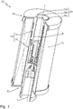
- Fig. 1 shows a filter element 10 according to the invention for filtering a liquid medium, such as engine or transmission oil of an oil circuit of a motor vehicle.
- the filter element 10 has a filter material 12, which is designed in the form of a multiply folded textile filter.
- the filter material 12 is arranged completely circumferentially around a central tube 14 of the filter element 10.
- the central tube 14 is arranged concentrically to the longitudinal axis L of the filter element 10.
- the first support tube 16 is part of a first end plate 20 of the filter element, ie, the first support tube 16 is the first end plate 20 of the filter element 10 integrally formed
- the second support tube 18 is accordingly part of a second end plate 22 of the filter element 10 and this formed.
- the support tubes 16, 18 extend from the respective end plates 20, 22 into the interior of the filter element 10 in the axial direction.
- the two end plates 20, 22 serve with their sections designed as a support tube 16, 18 as a cylindrical abutment and support surface for the filter material 12 in order to prevent this from collapsing.
- the two end plates 20, 22 also serve as covers, which secure the filter material 12 in the longitudinal direction of the filter element 10 and encompass (overlap).
- the end plates 20, 22 are each integrally formed to facilitate the manufacture and assembly of the filter element 10.
- the filter element 10 is provided with a bypass channel B for the liquid medium, through which the liquid medium can be passed through the filter element 10, bypassing the filter material 12.
- the first end plate 20 defines an inlet 24 of the bypass channel B, which in the present example, a first opening 26 a, a second Opening 26 b, a third opening 26 c and a fourth opening, which due to the sectional view according to Fig. 1 is not visible.
- the openings 26a, 26b, 26c and the fourth opening are arranged in a circular arc around the longitudinal axis L lined up one behind the other.
- the inlet 24 serves to discharge an overpressure on the filter element 10.
- the openings may not be too small. A sufficient fürströmitzkeit must be guaranteed.
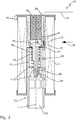
- Fig. 2 shows the filter element 10 in a sectional side view.
- the filter material 12 flows through the liquid medium transversely to the longitudinal axis L of the filter element 10, ie in a flow direction 28 directed radially to the longitudinal axis L.
- the filter element 10 has a clean room R, which is arranged in the flow direction 28 behind the filter material 12 in the interior of the filter element 10.
- the clean room R is fluidically connected to an outlet 30 of the filter element 10, via which the liquid medium can be led out of the first filter element 10.
- the liquid medium is cold, for example, it has a high viscosity, so that sufficient flow through the filter material 12 at normal operating pressures can not be guaranteed.
- the pressure of the unfiltered liquid medium in the flow direction 28 increases in front of the filter material 12.
- the liquid medium then flows in the direction of a second arrow 32 via the inlet 24 into the bypass channel B, as will be explained in more detail below.
- the bypass channel B is provided with a sieve 34, are separated by the coarser impurities from the guided over the bypass channel B liquid medium.
- the screen 34 is thus ensured that the guided over the filter element 10 liquid medium is freed in any operating state of the filter element 10 at least of coarser / coarse particulate impurities.
- the screen 34 is in sections or positively molded in or on the first end plate 20 formed of plastic or acting as a support means first support tube 16 in sections.
- the screen 34 is tubular in the embodiment shown here and protrudes from the first end plate 20 in the axial direction into the interior of the filter element 10 into it. As a result, no additional height for the screen 34 on the filter element 10 must be provided.
- the bypass channel B is fluidly connected via a bypass valve 36 to the clean room R and the outlet 30 of the filter element.
- the bypass valve 36 is designed in the sense of a one-way pressure relief valve and has a defined opening pressure.
- the bypass valve 36 includes a valve or closure member 40, the first end 42 is mushroom-shaped and the second end 44 has a plurality of barb-shaped securing elements 44.
- the first end 42 seals in the closed position of the bypass valve 36 shown a formed by the support tube 16 of the first end plate 20 output 46 of the bypass channel B.
- a spring element 38 For biased contact of the closure member 40 to the first end plate 20 is a spring element 38 which is supported at one end on the underside of the first end 42 of the closure member 40 and the other end on the second support tube 18 in the region of a guide recess 48 of the second support tube 18.
- the closure part 40 extends through the guide recess 48 and is axially displaceable in this relative to the two end plates 20, 22.
- the closure member 40 is inserted during assembly of the filter element 10 in the guide recess 48, wherein the closure member 40 is locked by means of the barb-shaped securing elements 44 with the support tube 18 of the second end plate 22 with axial play.
- the first end plate 20 has at its first support tube 16 further comprises a first latching projection 50 which is latched during assembly of the filter element 10 with a second latching projection 52 of the second support tube 18 of the second end plate 22.
- the filter element 10 can thereby be simply plugged together during assembly.
- bypass valve 36 Unless the pressurized unfiltered liquid medium exceeds the opening pressure of the bypass valve 36, the bypass valve 36 is actuated.
- the closure part 40 of the bypass valve 36 is against the force of the spring element 38 from the in Fig. 2 shown closed position in an unspecified reproduced open position in the direction of the second end plate 22 axially displaced. This releases a passage of the liquid medium via the bypass channel into the clean room R.
- the sieved liquid medium is led out of the filter element 10 via the outlet 30. Once the outside of the filter material 12 fitting Pressure of the unpurified liquid medium below the predetermined opening pressure of the bypass valve 36 decreases, the bypass valve 36 closes automatically. The liquid medium then flows exclusively through the filter material 12 into the filter element 10.
Landscapes
- Chemical & Material Sciences (AREA)
- Chemical Kinetics & Catalysis (AREA)
- Engineering & Computer Science (AREA)
- Mechanical Engineering (AREA)
- General Engineering & Computer Science (AREA)
- Filtration Of Liquid (AREA)
Description
Die Erfindung betrifft ein Filterelement zum Filtern eines Flüssigmediums, insbesondere von Motoren- oder Getriebeöl. Das Filterelement umfasst eine erste und eine zweite Endplatte sowie ein zwischen den beiden Endplatten angeordnetes Filtermaterial oder -medium, das von dem zu filtrierenden Flüssigmedium in einer zur Längsachse des Filterelements radialen Strömungsrichtung durchströmbar ist. In Strömungsrichtung hinter dem Filterelement ist ein Reinraum des Filterelements angeordnet, der mit einem Flüssigmedien-Auslass des Filterelements fluidisch verbunden ist. Das Filterelement ist mit einem sogenannten Bypass- oder Umgehungskanal für das Flüssigmedium versehen, über den das Flüssigmedium unter Umgehung des Filtermaterials durch das Filterelement führbar ist. Der Bypasskanal ist über ein Umgehungsventil mit dem Reinraum fluidisch verbunden und weist einen durch die erste Endplatte gebildeten Einlass für das Flüssigmedium auf. Dem Bypasskanal ist ein Sieb zugeordnet, um Feststoffe aus dem über den Bypasskanal geführten Flüssigmedium abzutrennen. Die Erfindung betrifft weiterhin eine Filteranordnung mit einem solchen Filterelement.The invention relates to a filter element for filtering a liquid medium, in particular engine or transmission oil. The filter element comprises a first and a second end plate and a filter material or medium arranged between the two end plates, which can be flowed through by the liquid medium to be filtered in a radial direction of flow relative to the longitudinal axis of the filter element. In the flow direction behind the filter element, a clean room of the filter element is arranged, which is fluidically connected to a liquid media outlet of the filter element. The filter element is provided with a so-called bypass or bypass channel for the liquid medium through which the liquid medium can be guided by bypassing the filter material through the filter element. The bypass passage is fluidly connected to the clean room via a bypass valve and has an inlet for the liquid medium formed by the first end plate. The bypass channel is associated with a screen to separate solids from the guided over the bypass channel liquid medium. The invention further relates to a filter assembly with such a filter element.
Es ist bekannt, Filterelemente in Kraftfahrzeugen einzusetzen, bei denen das Filtermedium, nicht zuletzt zur Vermeidung einer überdruckbedingten Beschädigung des Filtermaterials, mittels eines Bypasskanals um das Filtermaterial herumgeleitet wird. Dies ist beispielsweise im Falle von Ölfiltern notwendig, wenn das Flüssigmedium, also beispielsweise das Getriebe- oder Motorenöl, bei einem Kaltstart des Kraftfahrzeuges noch nicht flüssig genug ist, also noch eine zu hohe Viskosität aufweist, um das Filtermaterial zu passieren. Mit Hilfe dieser Umleitung kann ein hinreichend hoher Filtermedienfluss über das Filterelement in jedem Fall gewährleistet werden.It is known to use filter elements in motor vehicles, in which the filter medium, not least to avoid a pressure-related damage to the filter material, is guided around the filter material by means of a bypass channel. This is necessary, for example, in the case of oil filters, when the liquid medium, so for example, the transmission or engine oil, at a cold start of the motor vehicle is not liquid enough, so still has too high a viscosity to pass through the filter material. With the help of this diversion, a sufficiently high filter media flow over the filter element can be ensured in each case.
Aus der
Das Umgehen des Filtermaterials birgt grundsätzlich die Gefahr, dass das Flüssigmedium nach Verlassen des Filterelements noch größere Schmutzpartikel mit sich führt. Die
Die Anordnung eines Siebs zur Grob-Filterung des Filtermediums ist weiterhin aus der
Die
Die
Der Erfindung liegt die Aufgabe zugrunde, ein Filterelement und eine Filteranordnung der eingangs genannten Art bereitzustellen, durch die die vorgenannten Nachteile des Standes der Technik überwunden werden.The invention has for its object to provide a filter element and a filter assembly of the type mentioned, by which the aforementioned disadvantages of the prior art are overcome.
Die das Filterelement betreffende Aufgabe wird durch ein Filterelement mit den in Patentanspruch 1 angegebenen Merkmalen gelöst. Die erfindungsgemäße Filteranordnung weist die in Patentanspruch 10 angegebenen Merkmale auf.The object relating to the filter element is achieved by a filter element having the features specified in patent claim 1. The filter assembly according to the invention has the features specified in
Das erfindungsgemäße Filterelement zeichnet sich durch ein zuverlässiges Abtrennen (Aussieben) von Feststoff-Verunreinigungen aus dem über den Bypasskanal geführten Flüssigmedium aus. Die erste Endplatte kann gemeinsam mit der Stützeinrichtung des Siebs in einem einzigen Verfahrensschritt, beispielsweise im Spritzgussverfahren erzeugt werden. Zusätzliche Montageschritte zur Befestigung der Stützeinrichtung an der ersten Endplatte entfallen. Zugleich wird die Bauhöhe des Filterelements durch die erfindungsgemäße Anordnung des Siebs nicht beeinflusst. Eine fluidische Dichtheit der Anbindung des Siebs an der Stützeinrichtung selbst gegenüber hohen Drücken des Flüssigmediums kann auf einfache und kostengünstige Weise realisiert werden.The filter element according to the invention is characterized by a reliable separation (sifting out) of solid impurities from the liquid medium conducted via the bypass channel. The first end plate can be produced together with the support means of the screen in a single process step, for example by injection molding. Additional mounting steps for mounting the support means on the first end plate omitted. At the same time the height of the filter element is not affected by the arrangement of the invention sieve. A Fluidic tightness of the connection of the screen to the support device itself against high pressures of the liquid medium can be realized in a simple and cost-effective manner.
Das Sieb kann erfindungsgemäß an der ersten Endplatte bzw. der Stützeinrichtung abschnittsweise ein- oder angespritzt sein. Die daraus resultierende formschlüssig gehaltene Anordnung des Siebs an der ersten Endplatte gewährleistet einen verschleißfreien und fluiddichten Sitz des Siebs selbst bei hohen Drücken. Nach einer alternativen Weiterbildung kann das Sieb, soweit dies aus einem thermoplastischen Kunststoff besteht, auch mit der ersten Endplatte/Stützeinrichtung verschweißt sein.According to the invention, the sieve may be partially or integrally molded onto the first end plate or the support device. The resulting positively held arrangement of the screen on the first end plate ensures a wear-free and fluid-tight fit of the screen even at high pressures. According to an alternative development, the screen, as far as it consists of a thermoplastic material, also be welded to the first end plate / support means.
Das Sieb ist bevorzugt aus Polyamid gefertigt und kann im Bedarfsfall aus einem Edelstahl bestehen. Insgesamt können dadurch Schmutzpartikel auch bei korrosiven Flüssigmedien sicher aus dem Filtermedium gesiebt werden.The sieve is preferably made of polyamide and can, if necessary, consist of a stainless steel. Overall, dirt particles can be sieved safely out of the filter medium, even with corrosive liquid media.
In besonders bevorzugter Ausgestaltung der Erfindung weist das Sieb eine mittlere Porengröße bzw. Maschenweite zwischen 10 Mikrometer und 500 Mikrometer, insbesondere zwischen 50 Mikrometer und 200 Mikrometer, auf. Die mittlere Porengröße bzw. Maschenweite des Siebes ist dabei vorzugsweise circa zehn Mal so groß wie die mittlere Porengröße des Filtermaterials. Hierdurch kann sowohl eine hinreichende Filterung des Flüssigmediums als auch ein kontinuierlicher partikelfreier Fluss des Flüssigmediums, wenn dieses eine hohe Viskosität aufweist, gewährleistet werden.In a particularly preferred embodiment of the invention, the sieve has an average pore size or mesh size between 10 micrometers and 500 micrometers, in particular between 50 micrometers and 200 micrometers. The average pore size or mesh size of the screen is preferably approximately ten times as large as the mean pore size of the filter material. As a result, both a sufficient filtration of the liquid medium and a continuous particle-free flow of the liquid medium, if this has a high viscosity, can be ensured.
Nach einer bevorzugten Weiterbildung der Erfindung ist das Sieb röhrenförmig ausgebildet, um eine große (aktive) Siebfläche zur Verfügung zu stellen. Der Einlass des Bypasskanals ist dabei vorzugsweise mit der äußeren Mantelfläche des Siebes fluidisch verbunden. Das Flüssigmedium durchströmt das Sieb beim Einsatz des Filterelements somit "von außen nach innen" und wird dabei von gröberen bzw. groben Feststoffpartikeln befreit.According to a preferred embodiment of the invention, the screen is tubular in order to provide a large (active) screen area available. The inlet of the bypass channel is preferably fluidly connected to the outer surface of the screen. The liquid medium flows through the screen when using the filter element thus "from outside to inside" and is thereby freed from coarser or coarse solid particles.
Ein konstruktiv besonders einfacher Aufbau und zugleich gegenüber mechanischen Belastungen robuster Aufbau des Filterelements kann dadurch erreicht werden, dass die Stützeinrichtung als ein erstes Stützrohr ausgebildet ist, an dem das Filtermaterial außenseitig anliegt. Das Stützrohr erfüllt somit eine Doppelfunktion und stützt zusätzlich das Filtermaterial innenseitig ab. Zur Abstützung des Filtermaterials über dessen gesamte Längserstreckung kann sich das erste Stützrohr bis zur zweiten Endplatte des Filterelements erstrecken. Aus funktionalen Gründen muss eine ausreichend große Durchströmmöglichkeit am Stützrohr vorhanden sein.A structurally particularly simple construction and at the same time robust construction of the filter element with respect to mechanical loads can be achieved in that the support device is designed as a first support tube against which the filter material rests on the outside. The support tube thus fulfills a dual function and additionally supports the filter material on the inside. To support the filter material over its entire longitudinal extent, the first support tube to the second End plate of the filter element extend. For functional reasons, a sufficiently large Durchströmmöglichkeit the support tube must be present.
Alternativ kann an der zweiten Endplatte ein zweites Stützrohr angeordnet, insbesondere angeformt sein. Das zweite Stützrohr erstreckt sich dabei analog zum ersten Stützrohr von der zweiten Endplatte in axialer Richtung in das Innere des Filterelements, d.h. in Richtung auf die erste Endplatte. Das Filtermaterial liegt in diesem Fall an dem zweiten Stützrohr außenseitig an.Alternatively, a second support tube may be arranged, in particular molded, on the second end plate. The second support tube extends in the same way as the first support tube from the second end plate in the axial direction into the interior of the filter element, i. towards the first end plate. The filter material is in this case on the second support tube on the outside.
Eine besonders robuste und kostengünstige Bauart des Filterelements kann erfindungsgemäß dadurch realisiert werden, das das zweite Endplattenelement mit dem ersten Endplattenelement verrastbar ist. Die beiden Endplatten können in besonders einfacher Ausgestaltung des Filterelements über die beiden vorstehend erläuterten Stützrohre miteinander verrastet sein. Dadurch erübrigen sich separate Verbindungselemente und die Montage des Filterelements wird erleichtert.A particularly robust and cost-effective design of the filter element can be realized according to the invention in that the second end plate element can be latched to the first end plate element. The two end plates can be locked together in a particularly simple embodiment of the filter element via the two above-explained support tubes. This eliminates the need for separate fasteners and the assembly of the filter element is facilitated.
Die zweite Endplatte bildet unter konstruktiven wie auch fertigungstechnischen Aspekten vorzugsweise den Auslass des Filterelements. Dadurch können im Filterelement besonders große Strömungsquerschnitte für das Flüssigmedium realisiert werden.The second end plate preferably forms the outlet of the filter element under structural as well as manufacturing aspects. As a result, particularly large flow cross sections for the liquid medium can be realized in the filter element.
Das Umgehungs- oder Überdruckventil kann erfindungsgemäß ein Ventil- oder Verschlussteil aufweisen, das zwischen einer Schließstellung und einer Öffnungsstellung axial verschiebbar angeordnet ist, wobei das Verschlussteil in Schließstellung an dem ersten Stützrohr bzw. der ersten Endplatte dichtend anliegt und durch ein unter Vorspannung stehendes Federelement an dem zweiten Stützrohr abgestützt ist. Dadurch ergibt sich ein besonders einfacher und gegenüber Störungen wenig anfälliger Aufbau des Umgehungsventils. Das Federelement ist dabei vorzugsweise in Form einer Spiralfeder ausgebildet. Mittels des Federelements kann ein definierter Öffnungsdruck des Umgehungsventils auf einfache Weise vorgegeben werden.According to the invention, the bypass or overpressure valve can have a valve or closure part which is arranged so as to be axially displaceable between a closed position and an open position, wherein the closure part sealingly abuts against the first support tube or the first end plate in the closed position and by a prestressed spring element is supported the second support tube. This results in a particularly simple and less susceptible to interference structure of the bypass valve. The spring element is preferably designed in the form of a spiral spring. By means of the spring element, a defined opening pressure of the bypass valve can be specified in a simple manner.
Ein hohes Dichtvermögen bei gleichzeitiger einfacher konstruktiver Ausfertigung des Umgehungsventils kann dadurch erzielt werden, dass das Verschlussteil an seinem ersten der ersten Endplatte zuweisenden Ende pilzkopfförmig ausgebildet ist.A high sealing capacity with simultaneous simple construction of the bypass valve can be achieved in that the closure part is formed mushroom-head-shaped at its first end facing the first end plate.
Nach der Erfindung kann das Verschlussteil in einer Führungsausnehmung der zweiten Endplatte bzw. des zweiten Stützrohrs der Endplatte verschiebbar geführt sein. Zur erleichterten Montage des Filterelements kann das Verschlusselement dabei mit einem oder mehreren Sicherungselementen versehen sein, durch das/die ein unerwünschtes axiales Entfernen oder Herausfallen des Verschlussteils aus der Führungsausnehmung unterbunden ist. Dies ist für die Montage des Filterelements von Vorteil.According to the invention, the closure member is slidably guided in a guide recess of the second end plate and the second support tube of the end plate his. To facilitate assembly of the filter element, the closure element can be provided with one or more securing elements, by which an undesired axial removal or falling out of the closure part from the guide recess is prevented. This is advantageous for mounting the filter element.
Die Erfindung betrifft zusammenfassend ein Filterelement, bei dem ein Überdruck eines zu filtrierenden Flüssigmediums über ein Umgehungsventil abgeleitet werden kann. Dem Umgehungsventil ist ein Sieb fluidisch vorgeschaltet, so dass das Filtermedium auch dann keine groben Schmutzpartikel ausweist, wenn dieses über den Bypasskanal durch das Filterelement geführt wird. Das Filterelement weist ein Filtermaterial auf, das zwischen zwei Endplatten gehalten wird, wobei die erste Endplatte zur Ableitung des Überdrucks einen Einlass aufweist, der das Flüssigmedium zu dem röhrenförmig ausgebildeten Sieb und weiter zu dem Überdruckventil führt. Das Sieb ist an einer Stützeinrichtung befestigt, die an der ersten Endplatte angeformt ist und die sich entlang der Längsachse des Filterelements von der Endplatte in das Innere des Filterelements hineinerstreckt. Das Sieb kann insbesondere fest mit dem aus Kunststoff ausgebildeten ersten Endplattenelement vergossen sein. Eine besonders niedrige Bauhöhe des Filterelements kann dabei erzielt werden, wenn das Sieb rohrförmig und zentral und parallel zu dem in Längsrichtung des Filterelements ausgerichteten Filtermaterial an der ersten Endplatte befestigt ist.The invention relates in summary to a filter element in which an overpressure of a liquid medium to be filtered can be discharged via a bypass valve. The bypass valve is preceded by a sieve fluidly, so that the filter medium identifies no coarse dirt particles, even if it is passed through the filter element via the bypass channel. The filter element comprises a filter material held between two end plates, the first end plate having an inlet for discharging the positive pressure, which leads the liquid medium to the tubular sieve and further to the pressure relief valve. The screen is attached to a support formed on the first end plate and extending along the longitudinal axis of the filter element from the end plate into the interior of the filter element. In particular, the sieve can be cast solidly with the first end plate element made of plastic. A particularly low overall height of the filter element can be achieved if the screen is attached to the first end plate in a tubular and central manner and parallel to the filter material aligned in the longitudinal direction of the filter element.
Die erfindungsgemäße Aufgabe wird weiterhin durch eine Filteranordnung mit einem Gehäuse und einem in das Gehäuse eingesetzten, vorstehend beschriebenen Filterelement gelöst.The object of the invention is further achieved by a filter assembly having a housing and a filter element inserted into the housing, described above.
Weitere Merkmale und Vorteile der Erfindung ergeben sich aus der nachfolgenden detaillierten Beschreibung eines Ausführungsbeispiels der Erfindung, anhand der Figuren der Zeichnung, die erfindungswesentliche Einzelheiten zeigt sowie aus den Patentansprüchen.Further features and advantages of the invention will become apparent from the following detailed description of an embodiment of the invention, with reference to the figures of the drawing, which shows details essential to the invention and from the claims.
Die in der Zeichnung dargestellten Merkmale sind nicht notwendigerweise maßstäblich zu verstehen und derart dargestellt, dass die erfindungsgemäßen Besonderheiten deutlich sichtbar gemacht werden können. Die verschiedenen Merkmale können einzeln für sich oder zu mehreren in beliebigen Kombinationen bei Varianten der Erfindung verwirklicht sein.The features illustrated in the drawing are not necessarily to scale and illustrated in such a way that the features of the invention can be made clearly visible. The various features may be implemented individually for themselves or for a plurality in any combination in variants of the invention.
In der schematischen Zeichnung ist ein Ausführungsbeispiel der Erfindung dargestellt und in der nachfolgenden Beschreibung näher erläutert.In the schematic drawing an embodiment of the invention is shown and explained in more detail in the following description.
Es zeigen:
- Fig. 1
- eine teilweise geschnittene perspektivische Ansicht eines Filterelements; und
- Fig. 2
- eine vollständig geschnittene Seitenansicht des Filterelements aus
Fig. 1 .
- Fig. 1
- a partially cutaway perspective view of a filter element; and
- Fig. 2
- a fully cut side view of the filter element
Fig. 1 ,
Die Endplatten 20, 22 sind jeweils einteilig ausgebildet, um die Herstellung und Montage des Filterelements 10 zu erleichtern.The
Das Filterelement 10 ist mit einem Bypasskanal B für das Flüssigmedium versehen, durch den das Flüssigmedium unter Umgehung des Filtermaterials 12 durch das Filterelement 10 hindurchleitbar ist. Die erste Endplatte 20 begrenzt einen Einlass 24 des Bypasskanals B, der vorliegend beispielhaft eine erste Öffnung 26a, eine zweite Öffnung 26b, eine dritte Öffnung 26c sowie eine vierte Öffnung, die aufgrund der Schnittansicht gemäß
Ist das Flüssigmedium jedoch beispielsweise kalt, so weist es eine hohe Viskosität auf, so dass ein ausreichender Fluss durch das Filtermaterial 12 bei normalen Betriebsdrücken nicht gewährleistet werden kann. In diesem Fall steigt der Druck des ungefilterten Flüssigmediums in Strömungsrichtung 28 vor dem Filtermaterial 12. Das Flüssigmedium strömt dann in Richtung eines zweiten Pfeils 32 über den Einlass 24 in den Bypasskanal B, wie nachstehend näher erläutert wird.However, if the liquid medium is cold, for example, it has a high viscosity, so that sufficient flow through the
Wie in
Das Sieb 34 ist in oder an die aus Kunststoff gebildete erste Endplatte 20 bzw. das als Stützeinrichtung fungierende erste Stützrohr 16 abschnittsweise formschlüssig an- bzw. eingespritzt. Das Sieb 34 ist bei dem hier gezeigten Ausführungsbeispiel röhrenförmig ausgebildet und ragt von der ersten Endplatte 20 in axialer Richtung ins Innere des Filterelements 10 hinein. Hierdurch muss keine zusätzliche Bauhöhe für das Sieb 34 an dem Filterelement 10 vorgesehen werden.The
Der Bypasskanal B ist über ein Umgehungsventil 36 mit dem Reinraum R und dem Auslass 30 des Filterelements fluidisch verbunden. Das Umgehungsventil 36 ist im Sinne eines einwegigen Überdruckventils ausgebildet und weist einen definierten Öffnungsdruck auf.The bypass channel B is fluidly connected via a
Das Umgehungsventil 36 umfasst ein Ventil- oder Verschlussteil 40, dessen erstes Ende 42 pilzkopfförmig ausgebildet ist und dessen zweites Ende 44 mehrere widerhakenförmige Sicherungselemente 44 aufweist. Das erste Ende 42 dichtet in der gezeigten Schließstellung des Umgehungsventils 36 einen von dem Stützrohr 16 der ersten Endplatte 20 gebildeten Ausgang 46 des Bypasskanals B ab.The
Zur vorgespannten Anlage des Verschlussteils 40 an der ersten Endplatte 20 dient ein Federelement 38, das einenends an der Unterseite des ersten Endes 42 des Verschlussteils 40 und anderenends am zweiten Stützrohr 18 im Bereich einer Führungsausnehmung 48 des zweiten Stützrohrs 18 abgestützt ist. Das Verschlussteil 40 erstreckt sich durch die Führungsausnehmung 48 hindurch und ist in dieser relativ zu den beiden Endplatten 20, 22 axial verschiebbar gelagert.For biased contact of the
Das Verschlussteil 40 wird bei der Montage des Filterelements 10 in die Führungsausnehmung 48 eingeschoben, wobei das Verschlussteil 40 mittels der widerhakenförmigen Sicherungselemente 44 mit dem Stützrohr 18 der zweiten Endplatte 22 mit axialem Spiel verrastet.The
Die erste Endplatte 20 weist an ihrem ersten Stützrohr 16 weiterhin einen ersten Rastvorsprung 50 auf, der bei der Montage des Filterelements 10 mit einem zweiten Rastvorsprung 52 des zweiten Stützrohrs 18 des zweiten Endplatte 22 verrastet wird. Das Filterelement 10 kann dadurch bei der Montage einfach zusammengesteckt werden.The
Sofern das unter Druck stehende ungefilterte Flüssigmedium den Öffnungsdruck des Umgehungsventils 36 überschreitet, wird das Umgehungsventil 36 betätigt. Das Verschlussteil 40 des Umgehungsventils 36 wird gegen die Kraft des Federelements 38 aus der in
Claims (10)
- Filter element (10) for filtering a liquid medium, in particular of engine or transmission oil, comprising:- a first and a second end plate (20, 22);- a filter material (12) disposed between the two end plates (20, 22) and through which the liquid medium to be filtered can flow in a flow direction (28) radial to the longitudinal axis (L) of the filter element (10);- a clean room (R) disposed in flow direction (28) behind the filter material (12) and which is fluidically connected to an outlet (30) of the filter element (10);- a bypass channel (B) for the liquid medium fluidically connected to the clean room (R) via a bypass valve (36) and which features an inlet (24) formed by the first end plate (20); and- a sieve (34) allocated to the bypass channel (B) for separating solid particulates from the liquid medium conveyed by the bypass channel (B), characterized in that the sieve (34) is attached in a positive fitting to a supporting device which is integrally molded to the first end plate (20) and which extends along the longitudinal axis (L) of the filter element (10) from the end plate (20) into the interior of the filter element (10) and in that the sieve (34) is fluidically disposed upstream of the bypass valve (36).
- Filter element according to claim 1, characterized in that the sieve (34) is injected or welded to the supporting device.
- Filter element according to claim 1 or 2, characterized in that the sieve (34) has a tubular shape at least sectionwise.
- Filter element according to one of the preceding claims, characterized in that the supporting device is a first support tube (16) on which the filter material (12) abuts on the exterior side at least sectionwise.
- Filter element according to one of the preceding claims, characterized in that a second support tube (18) for the filter material (12) is integrally molded to the second end plate (22) on which the filter material (12) abuts on the exterior side.
- Filter element according to one of the above claims, characterized in that the two end plates (20, 22) are snap-connected to one another, preferably via the first and the second support tube (16, 18).
- Filter element according to one of the above claims, characterized in that the second end plate (22) is provided with the outlet (30).
- Filter element according to one of the claims 4 to 7, characterized in that the bypass valve (36) features a closing member (40) which is slidably axially disposed between a closed position and an opening position, wherein the closing member (40) in closed position sealingly contacts the first support tube (16) and is supported by the second support tube (18) by a spring element (38) which is under pretension.
- Filter element according to claim 8, characterized in that the closing member (40) is guided in a guide recess (48) of the second support tube (18) and provided at one end with a safety element (44).
- Filter arrangement with a housing and a filter element (10) inserted into the housing according to one of the above claims.
Applications Claiming Priority (1)
| Application Number | Priority Date | Filing Date | Title |
|---|---|---|---|
| DE102013017667.0A DE102013017667B4 (en) | 2013-10-25 | 2013-10-25 | Filter element with a bypass channel and filter assembly with a filter element |
Publications (2)
| Publication Number | Publication Date |
|---|---|
| EP2881156A1 EP2881156A1 (en) | 2015-06-10 |
| EP2881156B1 true EP2881156B1 (en) | 2019-01-16 |
Family
ID=51225277
Family Applications (1)
| Application Number | Title | Priority Date | Filing Date |
|---|---|---|---|
| EP14176671.7A Active EP2881156B1 (en) | 2013-10-25 | 2014-07-11 | Filter element having a bypass channel and filter assembly with a filter element |
Country Status (4)
| Country | Link |
|---|---|
| US (1) | US9410456B2 (en) |
| EP (1) | EP2881156B1 (en) |
| CN (1) | CN104548702B (en) |
| DE (1) | DE102013017667B4 (en) |
Families Citing this family (11)
| Publication number | Priority date | Publication date | Assignee | Title |
|---|---|---|---|---|
| DE102013017667B4 (en) * | 2013-10-25 | 2016-07-14 | Mann + Hummel Gmbh | Filter element with a bypass channel and filter assembly with a filter element |
| CH711424A1 (en) * | 2015-08-07 | 2017-02-15 | Drm Dr Müller Ag | Apparatus for attaching and sealing filter fabrics and membrane hoses to filter elements. |
| WO2017053270A1 (en) * | 2015-09-24 | 2017-03-30 | Cummins Filtration Ip, Inc. | System and method for oil filtration in bypass mode |
| DE202016103608U1 (en) * | 2016-07-06 | 2016-08-22 | Nordson Corporation | Filter device and cleaning device for removing dirt particles from a filter element of a filter device Filter device and cleaning device for removing dirt particles from a filter element of a filter device |
| DE102016012327A1 (en) * | 2016-10-17 | 2018-04-19 | Mann + Hummel Gmbh | Round filter element, in particular for gas filtration |
| DE102017005797A1 (en) * | 2017-06-21 | 2018-12-27 | Mann+Hummel Gmbh | Filter system with filter element and secondary element |
| DE102019107978A1 (en) * | 2018-03-29 | 2019-10-02 | Mann+Hummel Gmbh | Filter element and filter assembly |
| DE102020007481A1 (en) | 2020-12-08 | 2022-06-09 | Mercedes-Benz Group AG | Transmission for a motor vehicle, in particular for a motor vehicle |
| DE102022109929A1 (en) * | 2022-04-25 | 2023-10-26 | Mann+Hummel Gmbh | Filter element with valve device |
| DE102022110516B4 (en) | 2022-04-29 | 2026-04-30 | Robert Färber | BYPASS DEVICE FOR A FLUID TREATMENT SYSTEM, FLUID TREATMENT SYSTEM WITH THE SAME AND METHOD FOR OPERATING A FLUID TREATMENT SYSTEM |
| WO2025075764A1 (en) | 2023-10-03 | 2025-04-10 | Caterpillar Inc. | Hydraulic fluid filter with integrated bypass |
Family Cites Families (14)
| Publication number | Priority date | Publication date | Assignee | Title |
|---|---|---|---|---|
| US3297162A (en) * | 1963-09-04 | 1967-01-10 | Purolator Products Inc | Fluid filter with extended service life |
| US5225081A (en) * | 1989-09-07 | 1993-07-06 | Exxon Research And Engineering Co. | Method for removing polynuclear aromatics from used lubricating oils |
| DE59209746D1 (en) * | 1991-12-17 | 1999-10-21 | Mann & Hummel Filter | Filters for fuels and / or lubricants of an internal combustion engine |
| DE9411212U1 (en) * | 1994-07-13 | 1994-09-01 | Ing. Walter Hengst GmbH & Co KG, 48147 Münster | Liquid filter |
| GB9423823D0 (en) * | 1994-11-25 | 1995-01-11 | Glacier Metal Co Ltd | Improvements in and relating to filtration |
| DE20006974U1 (en) * | 2000-04-17 | 2001-08-23 | Ing. Walter Hengst GmbH & Co. KG, 48147 Münster | Liquid filter with strainer in front of the filter bypass valve |
| DE20006972U1 (en) | 2000-04-17 | 2001-08-23 | Ing. Walter Hengst GmbH & Co. KG, 48147 Münster | Liquid filter with sealing tube on the cover |
| WO2002032543A1 (en) | 2000-10-18 | 2002-04-25 | Argo Gmbh Für Fluidtechnik | Filter device |
| DE10063285A1 (en) | 2000-12-19 | 2002-06-20 | Ina Schaeffler Kg | Sieve filters for fluid lines, in particular for hydraulic pressure lines in internal combustion engines |
| US7166210B2 (en) | 2003-02-21 | 2007-01-23 | Deere & Company | Oil filter cartridge |
| DE202007000746U1 (en) | 2007-01-12 | 2008-05-21 | Mann+Hummel Gmbh | Fuel filter |
| DE102010054349B4 (en) * | 2009-12-17 | 2019-08-01 | Mann+Hummel Gmbh | Change filter element with sieve and filter assembly with such a filter element |
| DE102011005106A1 (en) | 2011-02-18 | 2012-08-23 | Hengst Gmbh & Co. Kg | Bypass valve, facility with bypass valve and filter element of the device |
| DE102013017667B4 (en) * | 2013-10-25 | 2016-07-14 | Mann + Hummel Gmbh | Filter element with a bypass channel and filter assembly with a filter element |
-
2013
- 2013-10-25 DE DE102013017667.0A patent/DE102013017667B4/en not_active Expired - Fee Related
-
2014
- 2014-07-11 EP EP14176671.7A patent/EP2881156B1/en active Active
- 2014-10-24 CN CN201410574645.6A patent/CN104548702B/en active Active
- 2014-10-25 US US14/523,881 patent/US9410456B2/en active Active
Non-Patent Citations (1)
| Title |
|---|
| None * |
Also Published As
| Publication number | Publication date |
|---|---|
| EP2881156A1 (en) | 2015-06-10 |
| DE102013017667B4 (en) | 2016-07-14 |
| CN104548702B (en) | 2018-09-25 |
| DE102013017667A1 (en) | 2015-04-30 |
| US20150114898A1 (en) | 2015-04-30 |
| US9410456B2 (en) | 2016-08-09 |
| CN104548702A (en) | 2015-04-29 |
Similar Documents
| Publication | Publication Date | Title |
|---|---|---|
| EP2881156B1 (en) | Filter element having a bypass channel and filter assembly with a filter element | |
| EP2649292B1 (en) | Fuel filter | |
| EP3017854B1 (en) | Filter for filtering of fluid | |
| EP3271043B1 (en) | Filter device | |
| DE102013012918B4 (en) | Liquid filter and filter element, in particular for fuel | |
| EP3641909B1 (en) | Filter system with filter elemetn and secondary element for closing a central tube | |
| DE102014016300B4 (en) | Filter and use of a hollow filter element in this filter | |
| WO2014202359A1 (en) | Hollow filter element, filter housing and filter | |
| WO2014082762A1 (en) | Filter, filter element, filter housing and discharge device of a filter | |
| EP2865433A2 (en) | Filter element and filter system for a liquid medium, particularly diesel fuel | |
| DE102016001025A1 (en) | Filter element of a liquid filter, liquid filter and filter housing | |
| WO2013178680A1 (en) | Filter device | |
| EP1648583B1 (en) | Oil filter arrangement and filter element | |
| EP3067102B1 (en) | Water separator and water separation system with integrated water discharge device | |
| DE102013012917B4 (en) | Liquid filters, in particular for fuel | |
| DE102006029107A1 (en) | Membrane for controlling flow of liquid stream in filter is located on filter support to form axial and/or radial seal between dirty and clean sides of filter | |
| WO2018146102A1 (en) | Fuel filter comprising a filter insert with a prefilter element and a main filter element | |
| EP3717099B1 (en) | Filter element of a filter for liquid, filter and filter housing | |
| EP4098346B1 (en) | Filter device | |
| DE102005058109B4 (en) | Use of a filter unit with a predetermined breaking point | |
| DE102007014813A1 (en) | filter means | |
| DE102013004865B4 (en) | Filter device with an annular filter element | |
| EP1917086A1 (en) | Oil filter assembly | |
| DE102013018199B4 (en) | Liquid filter, in particular for fuel | |
| WO2015135667A1 (en) | Strainer element for a fuel filter element featuring multistage water separation, and fuel filter element |
Legal Events
| Date | Code | Title | Description |
|---|---|---|---|
| PUAI | Public reference made under article 153(3) epc to a published international application that has entered the european phase |
Free format text: ORIGINAL CODE: 0009012 |
|
| 17P | Request for examination filed |
Effective date: 20140711 |
|
| AK | Designated contracting states |
Kind code of ref document: A1 Designated state(s): AL AT BE BG CH CY CZ DE DK EE ES FI FR GB GR HR HU IE IS IT LI LT LU LV MC MK MT NL NO PL PT RO RS SE SI SK SM TR |
|
| AX | Request for extension of the european patent |
Extension state: BA ME |
|
| R17P | Request for examination filed (corrected) |
Effective date: 20151201 |
|
| RBV | Designated contracting states (corrected) |
Designated state(s): AL AT BE BG CH CY CZ DE DK EE ES FI FR GB GR HR HU IE IS IT LI LT LU LV MC MK MT NL NO PL PT RO RS SE SI SK SM TR |
|
| STAA | Information on the status of an ep patent application or granted ep patent |
Free format text: STATUS: EXAMINATION IS IN PROGRESS |
|
| 17Q | First examination report despatched |
Effective date: 20170718 |
|
| GRAP | Despatch of communication of intention to grant a patent |
Free format text: ORIGINAL CODE: EPIDOSNIGR1 |
|
| STAA | Information on the status of an ep patent application or granted ep patent |
Free format text: STATUS: GRANT OF PATENT IS INTENDED |
|
| INTG | Intention to grant announced |
Effective date: 20180928 |
|
| GRAS | Grant fee paid |
Free format text: ORIGINAL CODE: EPIDOSNIGR3 |
|
| GRAA | (expected) grant |
Free format text: ORIGINAL CODE: 0009210 |
|
| STAA | Information on the status of an ep patent application or granted ep patent |
Free format text: STATUS: THE PATENT HAS BEEN GRANTED |
|
| AK | Designated contracting states |
Kind code of ref document: B1 Designated state(s): AL AT BE BG CH CY CZ DE DK EE ES FI FR GB GR HR HU IE IS IT LI LT LU LV MC MK MT NL NO PL PT RO RS SE SI SK SM TR |
|
| RAP1 | Party data changed (applicant data changed or rights of an application transferred) |
Owner name: MANN + HUMMEL GMBH |
|
| REG | Reference to a national code |
Ref country code: GB Ref legal event code: FG4D Free format text: NOT ENGLISH |
|
| RIN1 | Information on inventor provided before grant (corrected) |
Inventor name: JOKSCHAS, GUENTER Inventor name: SANCAR, ERCAN Inventor name: MAVROIDAKOS, PANAGIOTIS |
|
| REG | Reference to a national code |
Ref country code: CH Ref legal event code: EP |
|
| REG | Reference to a national code |
Ref country code: IE Ref legal event code: FG4D Free format text: LANGUAGE OF EP DOCUMENT: GERMAN |
|
| REG | Reference to a national code |
Ref country code: DE Ref legal event code: R096 Ref document number: 502014010641 Country of ref document: DE |
|
| REG | Reference to a national code |
Ref country code: AT Ref legal event code: REF Ref document number: 1089258 Country of ref document: AT Kind code of ref document: T Effective date: 20190215 |
|
| REG | Reference to a national code |
Ref country code: NL Ref legal event code: MP Effective date: 20190116 |
|
| REG | Reference to a national code |
Ref country code: LT Ref legal event code: MG4D |
|
| PG25 | Lapsed in a contracting state [announced via postgrant information from national office to epo] |
Ref country code: NL Free format text: LAPSE BECAUSE OF FAILURE TO SUBMIT A TRANSLATION OF THE DESCRIPTION OR TO PAY THE FEE WITHIN THE PRESCRIBED TIME-LIMIT Effective date: 20190116 |
|
| PG25 | Lapsed in a contracting state [announced via postgrant information from national office to epo] |
Ref country code: PT Free format text: LAPSE BECAUSE OF FAILURE TO SUBMIT A TRANSLATION OF THE DESCRIPTION OR TO PAY THE FEE WITHIN THE PRESCRIBED TIME-LIMIT Effective date: 20190516 Ref country code: ES Free format text: LAPSE BECAUSE OF FAILURE TO SUBMIT A TRANSLATION OF THE DESCRIPTION OR TO PAY THE FEE WITHIN THE PRESCRIBED TIME-LIMIT Effective date: 20190116 Ref country code: NO Free format text: LAPSE BECAUSE OF FAILURE TO SUBMIT A TRANSLATION OF THE DESCRIPTION OR TO PAY THE FEE WITHIN THE PRESCRIBED TIME-LIMIT Effective date: 20190416 Ref country code: FI Free format text: LAPSE BECAUSE OF FAILURE TO SUBMIT A TRANSLATION OF THE DESCRIPTION OR TO PAY THE FEE WITHIN THE PRESCRIBED TIME-LIMIT Effective date: 20190116 Ref country code: LT Free format text: LAPSE BECAUSE OF FAILURE TO SUBMIT A TRANSLATION OF THE DESCRIPTION OR TO PAY THE FEE WITHIN THE PRESCRIBED TIME-LIMIT Effective date: 20190116 Ref country code: SE Free format text: LAPSE BECAUSE OF FAILURE TO SUBMIT A TRANSLATION OF THE DESCRIPTION OR TO PAY THE FEE WITHIN THE PRESCRIBED TIME-LIMIT Effective date: 20190116 Ref country code: PL Free format text: LAPSE BECAUSE OF FAILURE TO SUBMIT A TRANSLATION OF THE DESCRIPTION OR TO PAY THE FEE WITHIN THE PRESCRIBED TIME-LIMIT Effective date: 20190116 |
|
| PG25 | Lapsed in a contracting state [announced via postgrant information from national office to epo] |
Ref country code: BG Free format text: LAPSE BECAUSE OF FAILURE TO SUBMIT A TRANSLATION OF THE DESCRIPTION OR TO PAY THE FEE WITHIN THE PRESCRIBED TIME-LIMIT Effective date: 20190416 Ref country code: HR Free format text: LAPSE BECAUSE OF FAILURE TO SUBMIT A TRANSLATION OF THE DESCRIPTION OR TO PAY THE FEE WITHIN THE PRESCRIBED TIME-LIMIT Effective date: 20190116 Ref country code: IS Free format text: LAPSE BECAUSE OF FAILURE TO SUBMIT A TRANSLATION OF THE DESCRIPTION OR TO PAY THE FEE WITHIN THE PRESCRIBED TIME-LIMIT Effective date: 20190516 Ref country code: LV Free format text: LAPSE BECAUSE OF FAILURE TO SUBMIT A TRANSLATION OF THE DESCRIPTION OR TO PAY THE FEE WITHIN THE PRESCRIBED TIME-LIMIT Effective date: 20190116 Ref country code: GR Free format text: LAPSE BECAUSE OF FAILURE TO SUBMIT A TRANSLATION OF THE DESCRIPTION OR TO PAY THE FEE WITHIN THE PRESCRIBED TIME-LIMIT Effective date: 20190417 Ref country code: RS Free format text: LAPSE BECAUSE OF FAILURE TO SUBMIT A TRANSLATION OF THE DESCRIPTION OR TO PAY THE FEE WITHIN THE PRESCRIBED TIME-LIMIT Effective date: 20190116 |
|
| REG | Reference to a national code |
Ref country code: DE Ref legal event code: R097 Ref document number: 502014010641 Country of ref document: DE |
|
| PG25 | Lapsed in a contracting state [announced via postgrant information from national office to epo] |
Ref country code: IT Free format text: LAPSE BECAUSE OF FAILURE TO SUBMIT A TRANSLATION OF THE DESCRIPTION OR TO PAY THE FEE WITHIN THE PRESCRIBED TIME-LIMIT Effective date: 20190116 Ref country code: SK Free format text: LAPSE BECAUSE OF FAILURE TO SUBMIT A TRANSLATION OF THE DESCRIPTION OR TO PAY THE FEE WITHIN THE PRESCRIBED TIME-LIMIT Effective date: 20190116 Ref country code: RO Free format text: LAPSE BECAUSE OF FAILURE TO SUBMIT A TRANSLATION OF THE DESCRIPTION OR TO PAY THE FEE WITHIN THE PRESCRIBED TIME-LIMIT Effective date: 20190116 Ref country code: CZ Free format text: LAPSE BECAUSE OF FAILURE TO SUBMIT A TRANSLATION OF THE DESCRIPTION OR TO PAY THE FEE WITHIN THE PRESCRIBED TIME-LIMIT Effective date: 20190116 Ref country code: DK Free format text: LAPSE BECAUSE OF FAILURE TO SUBMIT A TRANSLATION OF THE DESCRIPTION OR TO PAY THE FEE WITHIN THE PRESCRIBED TIME-LIMIT Effective date: 20190116 Ref country code: EE Free format text: LAPSE BECAUSE OF FAILURE TO SUBMIT A TRANSLATION OF THE DESCRIPTION OR TO PAY THE FEE WITHIN THE PRESCRIBED TIME-LIMIT Effective date: 20190116 Ref country code: AL Free format text: LAPSE BECAUSE OF FAILURE TO SUBMIT A TRANSLATION OF THE DESCRIPTION OR TO PAY THE FEE WITHIN THE PRESCRIBED TIME-LIMIT Effective date: 20190116 |
|
| PLBE | No opposition filed within time limit |
Free format text: ORIGINAL CODE: 0009261 |
|
| STAA | Information on the status of an ep patent application or granted ep patent |
Free format text: STATUS: NO OPPOSITION FILED WITHIN TIME LIMIT |
|
| PG25 | Lapsed in a contracting state [announced via postgrant information from national office to epo] |
Ref country code: SM Free format text: LAPSE BECAUSE OF FAILURE TO SUBMIT A TRANSLATION OF THE DESCRIPTION OR TO PAY THE FEE WITHIN THE PRESCRIBED TIME-LIMIT Effective date: 20190116 |
|
| 26N | No opposition filed |
Effective date: 20191017 |
|
| PG25 | Lapsed in a contracting state [announced via postgrant information from national office to epo] |
Ref country code: SI Free format text: LAPSE BECAUSE OF FAILURE TO SUBMIT A TRANSLATION OF THE DESCRIPTION OR TO PAY THE FEE WITHIN THE PRESCRIBED TIME-LIMIT Effective date: 20190116 Ref country code: MC Free format text: LAPSE BECAUSE OF FAILURE TO SUBMIT A TRANSLATION OF THE DESCRIPTION OR TO PAY THE FEE WITHIN THE PRESCRIBED TIME-LIMIT Effective date: 20190116 |
|
| REG | Reference to a national code |
Ref country code: CH Ref legal event code: PL |
|
| GBPC | Gb: european patent ceased through non-payment of renewal fee |
Effective date: 20190711 |
|
| PG25 | Lapsed in a contracting state [announced via postgrant information from national office to epo] |
Ref country code: TR Free format text: LAPSE BECAUSE OF FAILURE TO SUBMIT A TRANSLATION OF THE DESCRIPTION OR TO PAY THE FEE WITHIN THE PRESCRIBED TIME-LIMIT Effective date: 20190116 |
|
| REG | Reference to a national code |
Ref country code: BE Ref legal event code: MM Effective date: 20190731 |
|
| PG25 | Lapsed in a contracting state [announced via postgrant information from national office to epo] |
Ref country code: GB Free format text: LAPSE BECAUSE OF NON-PAYMENT OF DUE FEES Effective date: 20190711 |
|
| PG25 | Lapsed in a contracting state [announced via postgrant information from national office to epo] |
Ref country code: BE Free format text: LAPSE BECAUSE OF NON-PAYMENT OF DUE FEES Effective date: 20190731 Ref country code: LI Free format text: LAPSE BECAUSE OF NON-PAYMENT OF DUE FEES Effective date: 20190731 Ref country code: CH Free format text: LAPSE BECAUSE OF NON-PAYMENT OF DUE FEES Effective date: 20190731 Ref country code: LU Free format text: LAPSE BECAUSE OF NON-PAYMENT OF DUE FEES Effective date: 20190711 |
|
| PG25 | Lapsed in a contracting state [announced via postgrant information from national office to epo] |
Ref country code: FR Free format text: LAPSE BECAUSE OF NON-PAYMENT OF DUE FEES Effective date: 20190731 |
|
| PG25 | Lapsed in a contracting state [announced via postgrant information from national office to epo] |
Ref country code: IE Free format text: LAPSE BECAUSE OF NON-PAYMENT OF DUE FEES Effective date: 20190711 |
|
| REG | Reference to a national code |
Ref country code: AT Ref legal event code: MM01 Ref document number: 1089258 Country of ref document: AT Kind code of ref document: T Effective date: 20190711 |
|
| PG25 | Lapsed in a contracting state [announced via postgrant information from national office to epo] |
Ref country code: AT Free format text: LAPSE BECAUSE OF NON-PAYMENT OF DUE FEES Effective date: 20190711 |
|
| PG25 | Lapsed in a contracting state [announced via postgrant information from national office to epo] |
Ref country code: CY Free format text: LAPSE BECAUSE OF FAILURE TO SUBMIT A TRANSLATION OF THE DESCRIPTION OR TO PAY THE FEE WITHIN THE PRESCRIBED TIME-LIMIT Effective date: 20190116 |
|
| PG25 | Lapsed in a contracting state [announced via postgrant information from national office to epo] |
Ref country code: HU Free format text: LAPSE BECAUSE OF FAILURE TO SUBMIT A TRANSLATION OF THE DESCRIPTION OR TO PAY THE FEE WITHIN THE PRESCRIBED TIME-LIMIT; INVALID AB INITIO Effective date: 20140711 Ref country code: MT Free format text: LAPSE BECAUSE OF FAILURE TO SUBMIT A TRANSLATION OF THE DESCRIPTION OR TO PAY THE FEE WITHIN THE PRESCRIBED TIME-LIMIT Effective date: 20190116 |
|
| PG25 | Lapsed in a contracting state [announced via postgrant information from national office to epo] |
Ref country code: MK Free format text: LAPSE BECAUSE OF FAILURE TO SUBMIT A TRANSLATION OF THE DESCRIPTION OR TO PAY THE FEE WITHIN THE PRESCRIBED TIME-LIMIT Effective date: 20190116 |
|
| PGFP | Annual fee paid to national office [announced via postgrant information from national office to epo] |
Ref country code: DE Payment date: 20250722 Year of fee payment: 12 |