EP2030854B1 - Electric disk brake - Google Patents
Electric disk brake Download PDFInfo
- Publication number
- EP2030854B1 EP2030854B1 EP08013347.3A EP08013347A EP2030854B1 EP 2030854 B1 EP2030854 B1 EP 2030854B1 EP 08013347 A EP08013347 A EP 08013347A EP 2030854 B1 EP2030854 B1 EP 2030854B1
- Authority
- EP
- European Patent Office
- Prior art keywords
- brake
- pad
- electric motor
- electric
- pressing member
- Prior art date
- Legal status (The legal status is an assumption and is not a legal conclusion. Google has not performed a legal analysis and makes no representation as to the accuracy of the status listed.)
- Active
Links
Images


Classifications
-
- B—PERFORMING OPERATIONS; TRANSPORTING
- B60—VEHICLES IN GENERAL
- B60T—VEHICLE BRAKE CONTROL SYSTEMS OR PARTS THEREOF; BRAKE CONTROL SYSTEMS OR PARTS THEREOF, IN GENERAL; ARRANGEMENT OF BRAKING ELEMENTS ON VEHICLES IN GENERAL; PORTABLE DEVICES FOR PREVENTING UNWANTED MOVEMENT OF VEHICLES; VEHICLE MODIFICATIONS TO FACILITATE COOLING OF BRAKES
- B60T13/00—Transmitting braking action from initiating means to ultimate brake actuator with power assistance or drive; Brake systems incorporating such transmitting means, e.g. air-pressure brake systems
- B60T13/74—Transmitting braking action from initiating means to ultimate brake actuator with power assistance or drive; Brake systems incorporating such transmitting means, e.g. air-pressure brake systems with electrical assistance or drive
- B60T13/741—Transmitting braking action from initiating means to ultimate brake actuator with power assistance or drive; Brake systems incorporating such transmitting means, e.g. air-pressure brake systems with electrical assistance or drive acting on an ultimate actuator
-
- F—MECHANICAL ENGINEERING; LIGHTING; HEATING; WEAPONS; BLASTING
- F16—ENGINEERING ELEMENTS AND UNITS; GENERAL MEASURES FOR PRODUCING AND MAINTAINING EFFECTIVE FUNCTIONING OF MACHINES OR INSTALLATIONS; THERMAL INSULATION IN GENERAL
- F16D—COUPLINGS FOR TRANSMITTING ROTATION; CLUTCHES; BRAKES
- F16D65/00—Parts or details
- F16D65/14—Actuating mechanisms for brakes; Means for initiating operation at a predetermined position
- F16D65/16—Actuating mechanisms for brakes; Means for initiating operation at a predetermined position arranged in or on the brake
- F16D65/18—Actuating mechanisms for brakes; Means for initiating operation at a predetermined position arranged in or on the brake adapted for drawing members together, e.g. for disc brakes
-
- F—MECHANICAL ENGINEERING; LIGHTING; HEATING; WEAPONS; BLASTING
- F16—ENGINEERING ELEMENTS AND UNITS; GENERAL MEASURES FOR PRODUCING AND MAINTAINING EFFECTIVE FUNCTIONING OF MACHINES OR INSTALLATIONS; THERMAL INSULATION IN GENERAL
- F16D—COUPLINGS FOR TRANSMITTING ROTATION; CLUTCHES; BRAKES
- F16D2121/00—Type of actuator operation force
- F16D2121/18—Electric or magnetic
- F16D2121/24—Electric or magnetic using motors
-
- F—MECHANICAL ENGINEERING; LIGHTING; HEATING; WEAPONS; BLASTING
- F16—ENGINEERING ELEMENTS AND UNITS; GENERAL MEASURES FOR PRODUCING AND MAINTAINING EFFECTIVE FUNCTIONING OF MACHINES OR INSTALLATIONS; THERMAL INSULATION IN GENERAL
- F16D—COUPLINGS FOR TRANSMITTING ROTATION; CLUTCHES; BRAKES
- F16D2125/00—Components of actuators
- F16D2125/18—Mechanical mechanisms
- F16D2125/20—Mechanical mechanisms converting rotation to linear movement or vice versa
- F16D2125/34—Mechanical mechanisms converting rotation to linear movement or vice versa acting in the direction of the axis of rotation
- F16D2125/36—Helical cams, Ball-rotating ramps
-
- F—MECHANICAL ENGINEERING; LIGHTING; HEATING; WEAPONS; BLASTING
- F16—ENGINEERING ELEMENTS AND UNITS; GENERAL MEASURES FOR PRODUCING AND MAINTAINING EFFECTIVE FUNCTIONING OF MACHINES OR INSTALLATIONS; THERMAL INSULATION IN GENERAL
- F16D—COUPLINGS FOR TRANSMITTING ROTATION; CLUTCHES; BRAKES
- F16D2125/00—Components of actuators
- F16D2125/18—Mechanical mechanisms
- F16D2125/20—Mechanical mechanisms converting rotation to linear movement or vice versa
- F16D2125/34—Mechanical mechanisms converting rotation to linear movement or vice versa acting in the direction of the axis of rotation
- F16D2125/40—Screw-and-nut
-
- F—MECHANICAL ENGINEERING; LIGHTING; HEATING; WEAPONS; BLASTING
- F16—ENGINEERING ELEMENTS AND UNITS; GENERAL MEASURES FOR PRODUCING AND MAINTAINING EFFECTIVE FUNCTIONING OF MACHINES OR INSTALLATIONS; THERMAL INSULATION IN GENERAL
- F16D—COUPLINGS FOR TRANSMITTING ROTATION; CLUTCHES; BRAKES
- F16D2125/00—Components of actuators
- F16D2125/18—Mechanical mechanisms
- F16D2125/44—Mechanical mechanisms transmitting rotation
- F16D2125/46—Rotating members in mutual engagement
- F16D2125/54—Rotating members in mutual engagement with non-parallel non-stationary axes
Definitions
- the present invention relates to an electric disk brake which generates a brake force by pressing a brake pad to a disk rotor by use of an electric motor.
- Japanese Patent Public Disclosure 2003-202042 discloses an electric disk brake in which a rotational movement of a rotor of an electric motor is converted into a linear movement of a piston by use of a rotation-linear motion converting mechanism such as a ball screw mechanism or a ball ramp mechanism, and brake pads are pressed against a disk rotor by the piston, thereby generating a brake force.
- a force of a driver's pressing a brake pedal is detected by a sensor, and rotation of the electric motor is controlled by a controller based on the detected value, whereby a desired brake force can be generated.
- control accuracy can be improved by appropriate controlling of a brake force based on a thrust force of the piston or a rotational position of the electric motor.
- constant pad clearances can be maintained between the disk rotor and the brake pads based on the rotational position of the electric motor.
- JP 2002/213507 discloses features falling under the preamble of claim 1.
- the present invention has been contrived in consideration of this circumstance, and an object thereof is to provide an electric disk brake enabling prevention of uneven abrasion of a disk rotor.
- An aspect of the present invention is an electric disk brake, comprising:
- the pad-retracting-control electric current may be an electric current having an appropriate value to allow the brake pad to be maintained in a position to which the brake pad has retracted, after the brake pad has retracted due to contact of the disk rotor to the brake pad, when the brake is not in operation.
- the controller may control the electric motor such that, when the brake is not in operation, after the pad pressing member has retracted due to contact of the disk rotor to the brake pad, the pad pressing member further retracts by a predetermined distance from a position to which the pad pressing member has retracted.
- Still another aspect of the present invention is an electric disk brake, comprising:
- the controller when the brake is not in operation, the controller, after returning the pad pressing member to the predetermined position based on a detection result of the position detector, may supply the pad-retracting-control electric current to the electric motor so that the pad pressing member is maintained in the predetermined position.
- the controller may control the electric motor such that, when the brake is not in operation, after the pad pressing member has retracted due to contact of the disk rotor to the brake pad, the pad pressing member further retracts by a predetermined distance from a position to which the pad pressing member has retracted.
- the pad pressing member may be constantly urged backward by a urging unit.
- the controller may stop supplying the pad-retracting-control electric current to the electric motor when a vehicle is turning.
- the controller may stop supplying the pad-retracting-control electric current to the electric motor when a vehicle is running on a rough surface.
- an electric disk brake 1 comprises an electric disk brake main body 2 mounted on each of wheels of a vehicle, a stroke simulator 4 coupled with a brake pedal 3, a stroke sensor 5 which detects an operation stroke of the brake pedal 3 carried out by a driver, and a controller 7 (controlling means) which supplies a controlling electric current to the electric disk brake main body 2 based on detection results of various sensors such as the stroke sensor 5 and a vehicle speed sensor 6.
- the electric disk brake main body 2 is embodied as a floating caliper type disk brake.
- the main body 2 comprises a carrier 9, a pair of brake pads 10A and 10B, and caliper main body 11.
- the carrier 9 is fixed to a non-rotating portion (not shown) of a vehicle body side, such as a suspension member.
- the pair of brake pads 10A and 10B are disposed on respective sides of a disk rotor 8 which rotates together with the wheel, and are supported by the carrier 9.
- the caliper main body 11 is disposed so as to extend over or straddle the disk rotor 8, and is supported so as to be movable along an axis of the disk rotor 8 relative to the carrier 9.
- a cylindrical cylinder portion 12 and a claw portion 13 are integrally formed with the caliper main body 11.
- the cylinder portion 12 includes a through-hole open to one side of the disk rotor 8.
- the claw portion 13 extends from the cylinder portion 12 to the opposite side of the disk rotor 8 so as to straddle the disk rotor 8.
- a piston unit 14 and a motor unit 15 are disposed in the cylinder portion 12 of the caliper main body 11.
- the piston unit 14 is formed by integrally assembling a bottomed cylindrical piston 16 (pad pressing member), a ball ramp mechanism 17 (rotation-linear motion converting mechanism), a differential speed reducing mechanism 18, and a pad abrasion compensating mechanism 19.
- the piston 16 is slidably fitted in the cylinder portion 12, and contains the mechanisms 17 and 18 inside thereof.
- the ball ramp mechanism 17 comprises a rotation disk 20, a linear motion disk 21, and balls 22 (steel balls) disposed in an inclined groove between the rotation disk 20 and the linear motion disk 21.
- the rotation-linear motion converting mechanism is embodied by the ball ramp mechanism 17, although it may be embodied by, for example, a ball screw mechanism, a roller ramp mechanism, or a precision roller screw mechanism.
- the differential speed reducing mechanism 18 is interposed between the ball ramp mechanism 17 and an electric motor 23 of the motor unit 15.
- the mechanism 18 is adapted to reduce a rotation speed of a rotor 24 of the electric motor 23 according to a predetermined speed reducing ratio, and then transmit the slowed-down rotation to the rotation disk 20 of the ball ramp mechanism 17.
- the pad abrasion compensating mechanism 19 is adapted to advance an adjusting screw 25 to cause an advance of the ball ramp mechanism, when the brake pads 10A and 10B are abraded (or contact positions of the pads with the disk rotor 8 are changed).
- the motor unit 15 comprises the electric motor 23 and a resolver 26 (position detector) built therein.
- Application of an electric current to a coil of a stator 27 of the electric motor 23 causes the rotor 24 to rotate, whereby the ball ramp mechanism 17 is driven through the differential speed reducing mechanism 18.
- a rotational position of the rotor 24 is detected by the resolver 26.
- the electric disk brake main body 2 works as follows.
- the controller 7 supplies a controlling electric current to the electric motor 23 according to the detection result of the sensor 5, thereby causing a rotation of the rotor 24.
- the rotation of the rotor 24 is slowed down by the differential speed reducing mechanism 18 at the predetermined speed reducing ratio, and is converted to a linear motion by the ball ramp mechanism 17, and the piston 16 is advanced by the converted linear motion.
- the brake pad 10B or one of the brake pad pair is pressed against the disk rotor 8.
- a reactive force generated by this pressing displaces the caliper main body 11, causing the claw portion 13 to press the brake pad 10A or the other of the brake pad pair against the disk rotor 8, whereby a brake force is generated.
- Abrasion of the brake pads 10A and 10B is compensated by the pad abrasion compensating mechanism 19, in which the adjusting screw 25 of the mechanism 19 advances to push forward the ball ramp mechanism 17 by a distance corresponding to an abrasion amount.
- the controller 7 detects a vehicle condition such as a rotation speed of each wheel, a vehicle speed, a vehicle acceleration, a steering angle and a lateral acceleration of the vehicle, with use of various sensors such as the vehicle speed sensor 6. Then, the controller 7 controls a rotation of the electric motor 23 based on the detection results, whereby boost control, anti-lock control, traction control, vehicle stabilizing control and the like can be preformed.
- a vehicle condition such as a rotation speed of each wheel, a vehicle speed, a vehicle acceleration, a steering angle and a lateral acceleration of the vehicle.
- Fig. 7 illustrates how the controller 7 controls the electric disk brake main body 2.
- step S1 it is determined at step S1 whether the brake pedal 3 is operated. If the brake pedal 3 is operated (NO), then brake control is performed in a usual manner (as will be described later) at step 5. If it is determined at step S1 that the brake pedal 3 is not operated (YES), then it is determined at step S2 whether a position at which the brake pads 10A and 10B each contact the disk rotor 8 (pad contact position) is already detected. If it is determined at step S2 that the pad contact position is already detected (YES), then the flow proceeds to step S4. If the pad contact position is not yet detected (NO), the pad contact position is detected at step S3, and then the flow proceeds to step S4. A pad clearance control is performed at step S4.
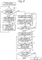
- Fig. 8 illustrates a process flow of the usual brake control performed at step S5 in Fig. 7 .
- step S5-1 it is determined at step S5-1 whether the brake pedal 3 is operated. Steps S5-2 and S5-3 are repeated until an operation of the brake pedal 3 is ended.
- a target rotational position of the electric motor 23 is set so as to generate a brake force (thrust force of the piston 16) according to a stroke of the brake pedal 3.
- a rotational position control is performed by supplying a controlling electric current so that the rotational position of the electric motor 23 matches the target rotational position.
- a relationship between the stroke of the brake pedal 3 and the target brake force at this time is determined based on the preset target brake force/pedal stroke characteristics, for example, as shown in Fig. 6 .
- the relationship between the rotational position of the electric motor 23 and the controlling electric current for generating a target brake force (target thrust force of the piston 16) is preset according to mechanical characteristics of the electric disk brake main body 2.
- the mechanical characteristics of the electric disk brake main body 2 are determined by specifications of components such as the ball ramp mechanism and the differential speed reducing mechanism, frictions at various portions, rigidity, and other factors.
- Fig. 3 shows the mechanical characteristics in a case that mechanical efficiency of the components such as the ball ramp mechanism and the differential speed reducing mechanism is good.
- Fig. 3(B) the relationship between the rotational position of the electric motor 23 and the brake force at a time of decreasing a brake force is similar to that at a time of increasing a brake force.
- Fig. 3(A) the relationship between the electric current supplied to the electric motor 23 and the brake force at the time of decreasing the brake force is slightly different from that at the time of increasing the brake force.
- an electric current at the time of decreasing the brake force is slightly less than that at the time of increasing the brake force, since a slight hysteresis exists. In this case, since the hysteresis is slight, the brake force reaches approximately zero when a value of electric current is zero at the time of decreasing the brake force.
- Fig. 4 shows mechanical characteristics in a case that mechanical efficiency of the components such as the ball ramp mechanism and the differential speed reducing mechanism is not so good.
- Fig. 4(B) the relationship between the rotational position of the electric motor 23 and the brake force at the time of decreasing the brake force is similar to that at the time of increasing the brake force.
- Fig. 4(A) the relationship between the electric current supplied to the electric motor 23 and the brake force at the time of decreasing the brake force is different from that at the time of increasing the brake force.
- an electric current at the time of the decreasing brake force is less than that at the time of increasing the brake force, since a hysteresis exists.
- the brake force does not reach zero when a value of electric current is zero at the time of decreasing brake force.
- an electric current should be supplied such that the electric motor 23 is rotated in a reverse direction.
- Fig. 5 shows mechanical characteristics in the case that a return spring is disposed at the electric disk brake main body 2 having the mechanical characteristics shown in Fig. 3 , so as to constantly urge or bias backward the piston 16.
- Fig. 5(B) the relationship between the rotational position of the electric motor 23 and the brake force at the time of decreasing the brake force is similar to that at the time of increasing the brake force, as is the case shown in Fig. 3 .
- the relationship between the electric current supplied to the electric motor 23 and the brake force at the time of decreasing the brake force is slightly different from that at the time of increasing the brake force.
- an electric current at the time of decreasing the brake force is slightly less than that at the time of increasing the brake force, since a slight hysteresis exists. Since an urging or biasing force of the return spring constantly affects the brake pads 10A and 10B so that the pads are displaced backward, and therefore a larger electric current should be supplied to the electric motor 23 to rotate the electric motor 23 for increasing the brake force against the urging force.
- the electric current at the time of decreasing the brake force is also larger than that shown in Fig. 3 . Therefore, it is certain that a value of the brake force becomes zero when a value of the electric current is zero. However, an electric current larger than zero should be applied in order to secure certain clearances between the brake pads 10A and 10B, and the disk rotor 8.
- the brake pedal 3 is pressed at time T0.
- a large controlling electric current is applied to quickly increase a brake force.
- the rotational position of the electric motor 23 is controlled so as to generate a brake force according to the pedal stroke.
- the rotational position of the electric motor 23 is maintained constant. Since this is an operation for increasing the brake force, the brake force can be maintained constant by continuously applying the controlling electric current of time T1.
- the rotational position of the electric motor 23 is controlled so as to weaken the brake force according to the pedal stroke. Since this is an operation for decreasing brake force, the applied controlling current is reduced by an amount corresponding to a mechanical hysteresis of the electric disk brake main body 2, as described before referring to Figs. 3 to 5 . As the brake stroke becomes constant from time T3, the rotational position of the electric motor 23 is maintained constant. Since this is an operation for decreasing brake force, the applied controlling electric current is increased by an amount corresponding to the mechanical hysteresis of the electric disk brake main body 2 so that the brake force is maintained constant. When the brake pedal is further released at time T4, the rotational position of the electric motor 23 is controlled so as to weaken the brake force according to the pedal stroke.
- the rotational position of the electric motor 23 is adjusted to the pad contact position such that the brake pads 10A and 10B contact the disk rotor 8.
- the pad clearance control is performed at time T6. That is, the rotational position of the electric motor 23 is controlled such that certain clearances are secured between the brake pads 10A and 10B, and the disk rotor 8.
- certain clearances are achieved at time T7, the electric motor 23 is stopped, and the rotational position at that time is kept.
- a controlling electric current applied to the electric motor 23 is monitored at step S3-1. Until the controlling electric current reaches a predetermined value, steps S3-2 and S3-3 are repeated so as to advance the brake pads 10A and 10B. Once the controlling electric current applied to the electric motor 23 reaches the predetermined value, the controlling electric current is set to zero at step S3-4, and the electric current application to the electric motor 23 is stopped at step S3-5. Then, the rotational position (stop position) of the electric motor 23 is monitored at step S3-6. When the rotation of the electric motor 23 is stopped, a reference position is set to the current position of the electric motor 23 at step S3-7. Then, steps S3-8 and S3-9 are performed so as to retract the brake pads 10A and 10A by a certain distance, and the position at this time is determined as the pad contact position, while the rotational position of the electric motor 23 is monitored at step S3-10.
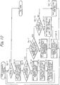
- Fig. 12 shows timing diagrams illustrating how the electric disk brake acts when the above-described pad-contact-position detection is carried out.
- an operation for the pad-contact-position detection is started at time T0, and the controlling electric current is supplied to the electric motor 23 so as to advance the brake pads 10A and 10B. Since the brake pads 10A and 10B start to contact the disk rotor 8 at time T1, load to the electric motor 23 (piston thrust force) is increased, and therefore the controlling electric current is increased (it should be noted that it is difficult to directly detect this start of increase in the controlling current).
- the controlling electric current reaches a predetermined electric current CS at time T2
- application of the controlling electric current is stopped. Because the controlling electric current application is stopped, the force of the piston pressing the brake pads 10A and 10B is weakened.
- the piston thrust force is decreased from Ft to Ff, and accordingly, the brake pads 10A and 10B are retracted by reactive forces of the brake pads 10A and 10B themselves generated by the contact of the pads to the disk rotor 8. Then, the pads reach respective release positions (fail open) at time T3 (it should be noted that it is difficult to directly detect this). At the release positions, the brake pads 10A and 10B still contact the disk rotor 8, and therefore the piston still holds the piston thrust force Ff.
- a reference position Xf is set to the position of the electric motor 23 at this time.
- the electric motor 23 is rotated in a reverse direction by a certain amount by a pad-retracting-control electric current Cc at time T4, and then the electric current application is stopped, whereby the piston thrust force becomes F0.
- the position at this time is determined as the pad contact position (time T5). If the brake pedal is not operated after that, the electric motor 23 is again rotated at time T6 such that the brake pads 10A and 10B are retracted by a certain amount, thereby obtaining certain pad clearances (time T7).
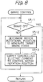
- a brake operation is monitored at step S4-1. If the brake is in operation, the flow returns to the main routine. If the brake is not in operation, then the current pad clearance is calculated at step S4-2. It is determined at step S4-3 whether the current pad clearance reaches a predetermined value. If the current pad clearance does not reach the predetermined value, then steps S4-4, S4-5 and S4-6 are repeated until the pad clearance reaches the predetermined value so that the electric motor 23 is rotated in a reverse direction to retract the brake pads 10A and 10B. By these steps, a predetermined pad clearance can be achieved.
- step S4-7 it is determined whether the pad retracting control is required. If the vehicle, for example, is running on a rough road or is turning to left or right, large acceleration affects the electric disk brake main body 2, and may cause the brake pads 10A, 10B and the piston 16 to be displaced. Therefore, in this case, the pad retracting control is not performed (NO), and at steps S4-8 and S4-9, the controlling electric current is supplied to the electric motor 23 to control the positions of the pads so that the brake pads 10A and 10B each are positioned with a constant distance, i.e., pad clearance (for example, approximately 0.3 mm) from the disk rotor 8.
- a constant distance i.e., pad clearance (for example, approximately 0.3 mm) from the disk rotor 8.
- step S4-10 If the vehicle is running in a normal condition (YES), the flow proceeds to step S4-10.
- the pad clearance is monitored at step S 4-10, and if the pad clearance reaches a limit value (for example, approximately 0.4 mm) (YES), then a target value of the pad clearance is set to the limit value at step S4-11.
- the pad clearance is adjusted to the limit value.
- the pad retracting control is performed at step S4-12.
- the pad retracting control of the brake pads 10A and 10B each having a pad clearance adjusted to a predetermined distance is performed by supplying to the electric motor 23 a pad-retracting-control electric current that is a lowest current for retracting the piston 16 but not sufficient for actually causing retracting of the piston 16.
- the pad-retracting-control electric current is small to such an extent that the current position of the piston 16 is maintained.
- This lowest electric current has a value around an electric current value when a brake force is zero. In the case of the electric disk brake having good mechanical efficiency as shown in Fig.
- the lowest electric current has a value around zero (designated by "a” in Fig. 3(A) ).
- the lowest electric current has a value around an electric current value (designated by "a” in Fig. 4(A) ) for rotating the electric motor 23 in a reverse direction.
- the lowest electric current has a value around an electric current value (designated by "b" in Fig.
- the piston 16 Since the lowest electric current is used as the pad-retracting-control electric current in this way, the piston 16 is maintained in the predetermined position when the brake is not in operation, so as to be displaced by application of an external force and stop at a position at that time upon removal of the external force. Therefore, when runout of the disk rotor 8 occurs and the disk rotor 8 contacts the brake pads 10A and 10B, the piston 16 is pushed backward through the brake pads 10A and 10B. At this time, the contact of the disk rotor 8 to the brake pads 10A and 10B triggers smooth retracting of not only the brake pads 10A and 10B but also the piston which is pressing the brake pad 10B or one of the pad pair.
- the brake pads 10A and 10B are usually maintained in respective positions such that they each have the predetermined pad clearance, but when runout occurs due to, for example, thermal deformation caused by a braking operation, and the disk rotor 8 contacts the brake pads 10A and 10B, the contact generates an external force to be applied to the piston 16.
- the piston 16, which usually restrains retracting of the brake pads 10A and 10B, can be smoothly retracted by receiving the external force, and can be maintained at the retracted position. Consequently, uneven abrasion of the brake pads 10A and 10B is suppressed, and thereby occurrence of brake judder due to uneven abrasion can be prevented.
- Fig. 13 shows timing diagrams illustrating how the electric disk brake main body 2 acts when the pad retracting control is preformed.
- the brake pedal is not operated, and the vehicle speed is changed only by an accelerator pedal.
- the pad retracting control is started.
- a pad-retracting-control electric current Cc is supplied to the electric motor 23 so that the piston 16 becomes ready to be displaced upon receiving an external force while keeping the pad clearance. Therefore, while the supply of the pad-retracting-control electric current Cc continues, the electric motor 23 is merely urged or biased but not actually rotated, and a rotational position Xc of the electric motor 23 is maintained.
- the piston 16 is also maintained in the position, and therefore the piston 16 does not generates a pressing force and the piston thrust force is maintained at F0.
- the pad retracting control is ended and the pad-retracting-control electric current Cc is returned to a usual electric current, and the usual pad clearance control (control of the positions of the brake pads 10A and 10B) is performed.
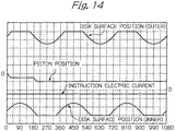
- the pad-retracting-control electric current (i.e., instruction electric current in Fig. 14 ) is supplied to the electric motor 23, whereby the piston 16 is ready to be displaced backward (downward as viewed in Fig. 14 ).
- an inner side surface of the disk rotor 8 contacts the brake pad 10B at 0° to 45°, whereby an external force is applied to the piston 16 from the brake pad 10B, and then the piston 16 is retracted.
- an outer side surface of the disk rotor 8 contacts the brake pad 10A at approximately 180°, whereby an external force is applied to the piston 16 from the brake pad 10A through the caliper main body 11, and then the position 16 is further retracted. After that, the disk rotor 8 does not contact the brake pads 10A and 10B, and therefore the piston 16 is maintained in the position to which the piston 16 has been retracted.
- the piston retracted due to contact of the disk rotor 8 is maintained in that position.
- displacement of the piston 16 at this time may be monitored, and when retracting of the brake pads 10A and 10B (piston 16) is triggered by contact of the disk rotor 8 due to, for example, runout of the disk rotor 8, the pad-retracting-control electric current may be increased, thereby further retracting the piston 16 by a constant distance from the position to which the piston 16 has been retracted.
- the pad-retracting-control electric current may be increased, thereby further retracting the piston 16 by a constant distance from the position to which the piston 16 has been retracted.
- a constant electric current is supplied as the pad-retracting-control electric current Cc.
- an electric current varying according to a predetermined pattern, or an electric current on which a dither current is superimposed may be used as the pad-retracting-control electric current Cc.
- the pad pressing member in a case where the brake is not in operation, when the disk rotor contacts the brake pads due 15 to, for example, runout of the disk rotor, the pad pressing member can be easily retracted, whereby it is possible to prevent uneven abrasion of the disk rotor, and therefore prevent brake judder or the like due to uneven abrasion of the disk rotor.
Landscapes
- Engineering & Computer Science (AREA)
- General Engineering & Computer Science (AREA)
- Mechanical Engineering (AREA)
- Transportation (AREA)
- Braking Arrangements (AREA)
- Braking Systems And Boosters (AREA)
Applications Claiming Priority (1)
| Application Number | Priority Date | Filing Date | Title |
|---|---|---|---|
| JP2007199537A JP4973994B2 (ja) | 2007-07-31 | 2007-07-31 | 電動ディスクブレーキ |
Publications (3)
| Publication Number | Publication Date |
|---|---|
| EP2030854A2 EP2030854A2 (en) | 2009-03-04 |
| EP2030854A3 EP2030854A3 (en) | 2015-01-14 |
| EP2030854B1 true EP2030854B1 (en) | 2020-03-25 |
Family
ID=40257002
Family Applications (1)
| Application Number | Title | Priority Date | Filing Date |
|---|---|---|---|
| EP08013347.3A Active EP2030854B1 (en) | 2007-07-31 | 2008-07-24 | Electric disk brake |
Country Status (3)
| Country | Link |
|---|---|
| US (1) | US8235474B2 (enExample) |
| EP (1) | EP2030854B1 (enExample) |
| JP (1) | JP4973994B2 (enExample) |
Families Citing this family (12)
| Publication number | Priority date | Publication date | Assignee | Title |
|---|---|---|---|---|
| US8220594B2 (en) * | 2007-08-30 | 2012-07-17 | Nippon Soken, Inc | Electric brake device |
| JP5333114B2 (ja) * | 2009-09-18 | 2013-11-06 | 株式会社アドヴィックス | 駐車ブレーキ制御装置 |
| JP5436191B2 (ja) * | 2009-12-21 | 2014-03-05 | Ntn株式会社 | インホイール型モータ内蔵センサ付き車輪用軸受装置 |
| JP5737500B2 (ja) * | 2011-01-31 | 2015-06-17 | 日立オートモティブシステムズ株式会社 | 電動ブレーキ装置 |
| JP5637067B2 (ja) * | 2011-05-24 | 2014-12-10 | 株式会社アドヴィックス | 電動ブレーキ装置および電動ブレーキ装置の制御方法 |
| JP6338902B2 (ja) * | 2014-03-24 | 2018-06-06 | Ntn株式会社 | 電動ブレーキ装置および電動ブレーキ装置システム |
| DE102015001152A1 (de) * | 2015-02-02 | 2016-08-04 | Wabco Europe Bvba | Verfahren zur Überwachung einer Bremse für Kraftfahrzeuge, Bremssystem zur Durchführung des Verfahrens sowie Kraftfahrzeug mit einem solchen |
| DE102015211359A1 (de) | 2015-06-19 | 2017-01-05 | Volkswagen Aktiengesellschaft | Vorbereitung eines Bremsvorganges in einem Kraftfahrzeug |
| KR102500083B1 (ko) * | 2018-03-08 | 2023-02-15 | 에이치엘만도 주식회사 | 전자식 브레이크 시스템 및 그 제어방법 |
| US12097833B2 (en) * | 2018-09-26 | 2024-09-24 | Hitachi Astemo, Ltd. | Electric brake, and control device |
| JP7169839B2 (ja) * | 2018-10-11 | 2022-11-11 | 日立Astemo株式会社 | ブレーキ制御装置及びブレーキシステム |
| KR20230036826A (ko) * | 2021-09-08 | 2023-03-15 | 현대모비스 주식회사 | 전동식 브레이크 |
Family Cites Families (17)
| Publication number | Priority date | Publication date | Assignee | Title |
|---|---|---|---|---|
| DE59804088D1 (de) * | 1997-11-22 | 2002-06-13 | Continental Teves Ag & Co Ohg | Verfahren und system zur ansteuerung einer elektromechanisch betätigbaren feststellbremse für kraftfahrzeuge |
| JP4000675B2 (ja) * | 1998-07-02 | 2007-10-31 | 住友電気工業株式会社 | 車両用ブレーキ装置 |
| US6250436B1 (en) * | 1998-07-31 | 2001-06-26 | Tokico Ltd. | Motor-driven brake apparatus |
| JP3695171B2 (ja) * | 1998-09-18 | 2005-09-14 | トヨタ自動車株式会社 | 車両用電動ブレーキ装置 |
| JP2001032868A (ja) * | 1999-07-21 | 2001-02-06 | Nissan Motor Co Ltd | 電動ブレーキ装置 |
| US6969126B2 (en) * | 2000-02-28 | 2005-11-29 | Hitachi, Ltd. | Braking apparatus and method of controlling the same |
| JP4248729B2 (ja) * | 2000-05-31 | 2009-04-02 | 株式会社日立製作所 | 電動ブレーキ装置 |
| US6626269B2 (en) * | 2000-08-08 | 2003-09-30 | Delphi Technologies, Inc. | Zero drag disc brake with anti-knock-back device |
| JP3740007B2 (ja) * | 2000-09-28 | 2006-01-25 | トヨタ自動車株式会社 | 車両用ブレーキの制御装置 |
| JP2002213507A (ja) * | 2001-01-17 | 2002-07-31 | Nissan Motor Co Ltd | 電動ブレーキ装置 |
| JP3936210B2 (ja) | 2001-10-22 | 2007-06-27 | 株式会社日立製作所 | 電動ディスクブレーキおよびその制御プログラム |
| DE10152423C2 (de) * | 2001-10-24 | 2003-08-21 | Lucas Automotive Gmbh | Scheibenbremse |
| US7481301B2 (en) * | 2003-11-17 | 2009-01-27 | Arvinmeritor Technology, Llc | Force sensor for vehicle brake application |
| US7467692B2 (en) * | 2005-03-17 | 2008-12-23 | Honeywell International Inc. | Method of and system for reducing power required for an electric brake to maintain a static force |
| JP2007199537A (ja) | 2006-01-27 | 2007-08-09 | Murata Mach Ltd | 画像形成装置 |
| US8544966B2 (en) * | 2008-01-17 | 2013-10-01 | Advics Co., Ltd. | Brake controller for vehicle and brake control method for vehicle |
| JP2009173082A (ja) * | 2008-01-22 | 2009-08-06 | Hitachi Ltd | ブレーキ装置 |
-
2007
- 2007-07-31 JP JP2007199537A patent/JP4973994B2/ja not_active Expired - Fee Related
-
2008
- 2008-07-22 US US12/219,423 patent/US8235474B2/en active Active
- 2008-07-24 EP EP08013347.3A patent/EP2030854B1/en active Active
Non-Patent Citations (1)
| Title |
|---|
| None * |
Also Published As
| Publication number | Publication date |
|---|---|
| EP2030854A2 (en) | 2009-03-04 |
| US8235474B2 (en) | 2012-08-07 |
| JP4973994B2 (ja) | 2012-07-11 |
| JP2009035069A (ja) | 2009-02-19 |
| US20090032342A1 (en) | 2009-02-05 |
| EP2030854A3 (en) | 2015-01-14 |
Similar Documents
| Publication | Publication Date | Title |
|---|---|---|
| EP2030854B1 (en) | Electric disk brake | |
| JP2009173082A (ja) | ブレーキ装置 | |
| JP5206952B2 (ja) | ディスクブレーキ装置 | |
| EP3858688B1 (en) | Electric brake, and control device | |
| WO2019163595A1 (ja) | 電動ブレーキおよび制御装置 | |
| JP2000055093A (ja) | 電動ディスクブレーキ装置 | |
| JP4546976B2 (ja) | ブレーキ装置 | |
| US10507810B2 (en) | Electric brake device | |
| JP4556153B2 (ja) | 電動ディスクブレーキ | |
| JP2000046082A (ja) | 電動ブレーキ装置 | |
| JP5556861B2 (ja) | ブレーキ装置 | |
| JP4191871B2 (ja) | ブレーキ装置 | |
| JP4941830B2 (ja) | 電動ディスクブレーキ | |
| JPH11257382A (ja) | 電動ディスクブレーキ | |
| JP2003104195A (ja) | 電動ブレーキ装置 | |
| JP4283077B2 (ja) | ブレーキ装置 | |
| JP5387830B2 (ja) | 電動ディスクブレーキ | |
| JP7153579B2 (ja) | ブレーキ装置 | |
| JP2008133922A (ja) | 電動ディスクブレーキ装置 | |
| JP5085108B2 (ja) | 電動ディスクブレーキ装置 | |
| JP2010006165A (ja) | 電動ディスクブレーキ | |
| JP2004239324A (ja) | 電気式ディスクブレーキのパッドクリアランス調整方法 | |
| JP4623316B2 (ja) | 電動ディスクブレーキ | |
| JP2020026240A (ja) | 車両用ブレーキシステム | |
| KR101714261B1 (ko) | 브레이크 녹 백 보상 시스템 및 방법 |
Legal Events
| Date | Code | Title | Description |
|---|---|---|---|
| PUAI | Public reference made under article 153(3) epc to a published international application that has entered the european phase |
Free format text: ORIGINAL CODE: 0009012 |
|
| AK | Designated contracting states |
Kind code of ref document: A2 Designated state(s): AT BE BG CH CY CZ DE DK EE ES FI FR GB GR HR HU IE IS IT LI LT LU LV MC MT NL NO PL PT RO SE SI SK TR |
|
| AX | Request for extension of the european patent |
Extension state: AL BA MK RS |
|
| PUAL | Search report despatched |
Free format text: ORIGINAL CODE: 0009013 |
|
| AK | Designated contracting states |
Kind code of ref document: A3 Designated state(s): AT BE BG CH CY CZ DE DK EE ES FI FR GB GR HR HU IE IS IT LI LT LU LV MC MT NL NO PL PT RO SE SI SK TR |
|
| AX | Request for extension of the european patent |
Extension state: AL BA MK RS |
|
| RIC1 | Information provided on ipc code assigned before grant |
Ipc: F16D 65/14 20060101ALI20141208BHEP Ipc: B60T 13/74 20060101AFI20141208BHEP |
|
| 17P | Request for examination filed |
Effective date: 20150701 |
|
| RBV | Designated contracting states (corrected) |
Designated state(s): AT BE BG CH CY CZ DE DK EE ES FI FR GB GR HR HU IE IS IT LI LT LU LV MC MT NL NO PL PT RO SE SI SK TR |
|
| AKX | Designation fees paid |
Designated state(s): DE |
|
| AXX | Extension fees paid |
Extension state: RS Extension state: BA Extension state: AL Extension state: MK |
|
| GRAP | Despatch of communication of intention to grant a patent |
Free format text: ORIGINAL CODE: EPIDOSNIGR1 |
|
| INTG | Intention to grant announced |
Effective date: 20191127 |
|
| RIN1 | Information on inventor provided before grant (corrected) |
Inventor name: YAMAGUCHI, TOHMA |
|
| GRAS | Grant fee paid |
Free format text: ORIGINAL CODE: EPIDOSNIGR3 |
|
| GRAA | (expected) grant |
Free format text: ORIGINAL CODE: 0009210 |
|
| STAA | Information on the status of an ep patent application or granted ep patent |
Free format text: STATUS: THE PATENT HAS BEEN GRANTED |
|
| AK | Designated contracting states |
Kind code of ref document: B1 Designated state(s): DE |
|
| RIN1 | Information on inventor provided before grant (corrected) |
Inventor name: YAMAGUCHI, TOHMA |
|
| REG | Reference to a national code |
Ref country code: DE Ref legal event code: R096 Ref document number: 602008062372 Country of ref document: DE |
|
| REG | Reference to a national code |
Ref country code: DE Ref legal event code: R097 Ref document number: 602008062372 Country of ref document: DE |
|
| PLBE | No opposition filed within time limit |
Free format text: ORIGINAL CODE: 0009261 |
|
| STAA | Information on the status of an ep patent application or granted ep patent |
Free format text: STATUS: NO OPPOSITION FILED WITHIN TIME LIMIT |
|
| 26N | No opposition filed |
Effective date: 20210112 |
|
| REG | Reference to a national code |
Ref country code: DE Ref legal event code: R081 Ref document number: 602008062372 Country of ref document: DE Owner name: HITACHI ASTEMO, LTD., HITACHINAKA-SHI, JP Free format text: FORMER OWNER: HITACHI, LTD., TOKYO, JP |
|
| PGFP | Annual fee paid to national office [announced via postgrant information from national office to epo] |
Ref country code: DE Payment date: 20250728 Year of fee payment: 18 |