EP2030786A2 - Method for pressing a surface coating of at least one layer onto a wood board - Google Patents
Method for pressing a surface coating of at least one layer onto a wood board Download PDFInfo
- Publication number
- EP2030786A2 EP2030786A2 EP08015107A EP08015107A EP2030786A2 EP 2030786 A2 EP2030786 A2 EP 2030786A2 EP 08015107 A EP08015107 A EP 08015107A EP 08015107 A EP08015107 A EP 08015107A EP 2030786 A2 EP2030786 A2 EP 2030786A2
- Authority
- EP
- European Patent Office
- Prior art keywords
- conveyor belt
- press
- wood
- short
- pressing
- Prior art date
- Legal status (The legal status is an assumption and is not a legal conclusion. Google has not performed a legal analysis and makes no representation as to the accuracy of the status listed.)
- Granted
Links
Images

Classifications
-
- B—PERFORMING OPERATIONS; TRANSPORTING
- B27—WORKING OR PRESERVING WOOD OR SIMILAR MATERIAL; NAILING OR STAPLING MACHINES IN GENERAL
- B27N—MANUFACTURE BY DRY PROCESSES OF ARTICLES, WITH OR WITHOUT ORGANIC BINDING AGENTS, MADE FROM PARTICLES OR FIBRES CONSISTING OF WOOD OR OTHER LIGNOCELLULOSIC OR LIKE ORGANIC MATERIAL
- B27N3/00—Manufacture of substantially flat articles, e.g. boards, from particles or fibres
- B27N3/08—Moulding or pressing
- B27N3/20—Moulding or pressing characterised by using platen-presses
- B27N3/22—Charging or discharging
-
- B—PERFORMING OPERATIONS; TRANSPORTING
- B27—WORKING OR PRESERVING WOOD OR SIMILAR MATERIAL; NAILING OR STAPLING MACHINES IN GENERAL
- B27N—MANUFACTURE BY DRY PROCESSES OF ARTICLES, WITH OR WITHOUT ORGANIC BINDING AGENTS, MADE FROM PARTICLES OR FIBRES CONSISTING OF WOOD OR OTHER LIGNOCELLULOSIC OR LIKE ORGANIC MATERIAL
- B27N3/00—Manufacture of substantially flat articles, e.g. boards, from particles or fibres
- B27N3/08—Moulding or pressing
- B27N3/20—Moulding or pressing characterised by using platen-presses
-
- B—PERFORMING OPERATIONS; TRANSPORTING
- B27—WORKING OR PRESERVING WOOD OR SIMILAR MATERIAL; NAILING OR STAPLING MACHINES IN GENERAL
- B27N—MANUFACTURE BY DRY PROCESSES OF ARTICLES, WITH OR WITHOUT ORGANIC BINDING AGENTS, MADE FROM PARTICLES OR FIBRES CONSISTING OF WOOD OR OTHER LIGNOCELLULOSIC OR LIKE ORGANIC MATERIAL
- B27N7/00—After-treatment, e.g. reducing swelling or shrinkage, surfacing; Protecting the edges of boards against access of humidity
- B27N7/005—Coating boards, e.g. with a finishing or decorating layer
-
- B—PERFORMING OPERATIONS; TRANSPORTING
- B30—PRESSES
- B30B—PRESSES IN GENERAL
- B30B15/00—Details of, or accessories for, presses; Auxiliary measures in connection with pressing
- B30B15/30—Feeding material to presses
-
- B—PERFORMING OPERATIONS; TRANSPORTING
- B32—LAYERED PRODUCTS
- B32B—LAYERED PRODUCTS, i.e. PRODUCTS BUILT-UP OF STRATA OF FLAT OR NON-FLAT, e.g. CELLULAR OR HONEYCOMB, FORM
- B32B38/00—Ancillary operations in connection with laminating processes
- B32B38/18—Handling of layers or the laminate
-
- B—PERFORMING OPERATIONS; TRANSPORTING
- B44—DECORATIVE ARTS
- B44C—PRODUCING DECORATIVE EFFECTS; MOSAICS; TARSIA WORK; PAPERHANGING
- B44C5/00—Processes for producing special ornamental bodies
- B44C5/04—Ornamental plaques, e.g. decorative panels, decorative veneers
- B44C5/043—Ornamental plaques, e.g. decorative panels, decorative veneers containing wooden elements
-
- B—PERFORMING OPERATIONS; TRANSPORTING
- B32—LAYERED PRODUCTS
- B32B—LAYERED PRODUCTS, i.e. PRODUCTS BUILT-UP OF STRATA OF FLAT OR NON-FLAT, e.g. CELLULAR OR HONEYCOMB, FORM
- B32B2317/00—Animal or vegetable based
- B32B2317/16—Wood, e.g. woodboard, fibreboard, woodchips
Definitions
- the invention relates to a method for pressing a at least single-layer surface coating on a wood-based panel, wherein the wood-based panel has a bottom applied, dried, non-cured, thermosetting resin layer, in a short-cycle press comprising an upper and a lower heatable press plate and a feeder. Furthermore, the invention relates to a feeder for a short-cycle press and a short-cycle press.
- Wood-based panels include all materials that are made of wood or predominantly of wood and that are in plate form in processed form. Wood-based panels can be made of veneer of different thickness, as well as strips, wood fibers or a combination thereof.
- Wood-based panels are coated for various applications. This is done to give the surface a certain look and / or to make the surface less sensitive to certain loads.
- the plate is provided with a decor which is either painted on, sprayed on, printed or applied in the form of a printed paper.
- the decorative layer must be protected by an additional coating usually. This can be done through an overlay, a soaked with thermosetting resin, transparent paper.
- the thermosetting resins used in the cured state have a good resistance to wear, which, if necessary, by additives such. B. corundum particles, can still be increased.
- Thermosetting synthetic resins such as phenolic resins, melamine and / or urea resins, can processed liquid and pre-dried, but cure only with the simultaneous action of pressure (about 20-40 bar) and heat (eg., 180 ° C). In industrial production, this is done in a heated press, which presses the overlay (and the decor) with the wood-based panel.
- These synthetic resins have the undesirable property of undergoing shrinkage during curing, resulting in stresses when pressed against the surface of the plate which deform the plate and thus render it useless.
- a counter-pull typically in the form of a resin impregnated paper, similar to the overlay applied to the opposite side of the plate. This ensures that compensate for the stresses on the top and bottom of each other.
- the package is secured by means of a loading device which hangs up the layers of the package on longitudinally arranged strips, optionally clamped on these strips and then transported the frame with the packages in the press.
- the strips must be removed and returned before the actual pressing process.
- the high cost of handling the feeder leads to long cycle times and reduces the cost of the process.
- thermosetting resin For pressing the package typically short-cycle presses are used, which are characterized by comparatively short pressing times (about 10 seconds).
- Such a press for pressing coatings containing thermosetting resin requires as functional parts, two press plates, which are heatable, and which can be pressed against each other with high pressure.
- charging time here and hereinafter refers to the time which elapses between the end of a pressing operation, characterized by the lifting off of the pressing plates from the wood-based panel, and the beginning of the next pressing operation, characterized by the placement of the pressing plates. This period includes the process of press plates, the discharge of the compressed wood-based panel and the retraction of the next wood-based panel.
- the object is achieved by a method according to claim 1.
- a method for pressing an at least single-layer surface coating on a wood-based panel in a short-cycle press comprising an upper and a lower heatable press plate and a feeder, at least one layer of a coating material by means of the feeder the top of the wood-based panel having a bottom applied, dried, uncured thermosetting resin layer, positioned and held in a defined position. Then the wood-based panel is placed in the space between the press plates and then the surface coating is pressed with the wood-based panel. Finally, the coated wood-based panel is discharged.
- a loading device for a short-cycle press according to claim 9.
- This comprises a conveyor belt according to the invention, which passes through a short-cycle press, wherein in the operating state a wood-based panel and at least one layer of coating material rest on the conveyor belt and secured there by means for securing position position position changes are.
- the press plates of the short-cycle press used can basically be arranged differently.
- an arrangement of the plates is one above the other, wherein the lower plate remains stationary during the pressing while the upper plate is lowered.
- the press plates are hereinafter referred to as "lower” and “upper” plate, whereby other embodiments of the invention, however, should not be excluded.
- the liquid countermix is melamine, a phenolic resin and / or a urea resin, since these resins are distinguished by numerous advantageous material properties and low material costs.
- the liquid backing is applied to the underside of the wood-based panel and dried, but not cured. As a result, the wood-based panel can be easily manipulated without a separate counter-pull is to handle. Slipping of the plate on the return is excluded.
- the surface coating in accordance with the structure of the surface coating known from conventional methods, preferably consists of two or more layers. This allows a more flexible design of the surface. So you can, for example Combine the attractive appearance of one or more decorative layers with the robustness of an overlying layer of abrasion resistant paint or resin.
- a stopper that can be integrated in a conveyor belt that leads into the press is sufficient here.
- a stop any type of device is referred to in this context, which secures the pressed material in at least one direction against horizontal position change.
- a respective stop is formed by strips, which are aligned transversely to the direction of the conveyor belt.
- the conveyor belt has several stops.
- means for securing the position of a wood-based panel are arranged on or in the short-cycle press. This offers the great advantage that even with a non-exact positioning of the conveyor belt, the wood-based panel is correctly positioned with respect to the short-cycle press. It may be in this embodiment z. B. act on slidable strips that serve as a stop when aligning the wood-based panel and the surface coating, but which are moved when conveying the plate or when moving the press.
- the conveyor belt runs over the lower press plate, so that by means of the belt, the pressed material can be introduced between the two press plates, and runs back below the press plate. Since the conveyor belt is located between the lower heatable plate and the pressed material during pressing, it must be resistant to the typically occurring temperatures, ie at least 200 ° C., preferably at least 250 ° C., more preferably at least 280 ° C, on the other hand, it should have a sufficiently high thermal conductivity, so as not to delay the heating of the pressed material.
- the thermal conductivity should be above 5 JK -1 m -1 s -1 , which is fulfilled, for example, for all metallic materials. Preference is given to a thermal conductivity of more than 20 JK -1 m -1 s -1 , more preferably more than 150 JK -1 m -1 s -1 .
- the conveyor belt is made of aramid and is coated with polytetrafluoroethylene.
- the necessary power consumption of the feeder is drastically reduced. It is in a further development of the invention below 40 kW, preferably below 30 kW, more preferably below 20 kW.
- the loading device comprises a device for removing the compressed materials.
- This can, for. B. manipulate the plates by means of suction lifters, but other mechanisms are possible.
- the transport of the pressed material or the coated plates between acceptance and removal can be done by means of one or more conveyor belts. Different variants are conceivable.
- the loading device comprises a conveyor belt which passes into a loading station, the short-cycle press and a removal station.
- This design ensures a safe positioning of the plates during loading, pressing and removal. Furthermore, you only need a drive, resulting in low operating and maintenance costs.
- the loading device comprises a first conveyor belt which passes through the loading station and the short-cycle press, and a second conveyor belt, which is subsequently arranged on the first conveyor belt and passes through the removal station.
- a different material can be selected for the second conveyor belt than for the first, since the second belt is not exposed to the high temperatures of the pressing operation.
- the loading device comprises a first conveyor belt which passes through the loading station and a second conveyor belt which is subsequently arranged on the first conveyor belt and which passes through the short-cycle press and the removal station.
- the first conveyor belt may be made of a material having no particular temperature resistance or thermal conductivity because it is not involved in the pressing operation. This allows the choice of a material that z. B. is inexpensive and / or easy.
- the loading device comprises a first conveyor belt which passes through the loading station and a second conveyor belt which is subsequently arranged on the first conveyor belt and passes through the short-cycle press and a third conveyor belt which is subsequently arranged on the second conveyor belt and passes through the removal station.
- the charging time in the present invention is less than 8 seconds, preferably less than 7 seconds. Charging times of 5-6 seconds are possible. This value is below the state of the art typical of about 8-12 seconds.
- the pressing time can be shortened because of the simplified loading process, the critical time, ie the time from the beginning of the introduction of the package in the press is reduced to the pressing.
- the critical time also affects the pressing time, since an unwanted premature curing of the thermosetting resin can take place during the lying time. Such a prematurely cured resin layer is unusable. Since the curing is faster, the higher the temperature, the temperature must be kept below a certain value during the critical time, which is essentially the temperature for the pressing process is given, as a change within the short cycle times is practically impossible. Thus, however, the pressing time is limited down.
- the critical lying time can be significantly reduced, on the one hand eliminates the removal of the frame, on the other hand by the absence of the same introduced into the press package is lower and thus the stroke of the upper press plate between the open and closed position smaller. Therefore, the closing can be done faster. Thanks to the shorter lay time, the temperature of the press plates in the present process is at least 180 ° C, preferably at least 220 ° C, more preferably at least 250 ° C, whereby the pressing time to less than 10 seconds, preferably less than 8 seconds, more preferably less than 7 seconds , lower.
- the charging time is not greater than the pressing time.
- the advantages of the present invention are on the one hand in the shorter cycle time, due to the shorter loading and pressing time. As a result, a higher productivity of the system is achieved. Since the heavy loaders and emptying omitted, the system can be operated with less power. Also, the cost of purchase, maintenance and repair of the strips to secure the Preßgutwovene be saved. Since the feeder only has to move small loads, it is subject to less wear. The return process for the strips is eliminated, thus saving energy, costs and space.
- the conveyor belt is divided into a feed conveyor belt 1, a press conveyor belt 2 and a pickup conveyor belt 3, which are arranged adjacent to each other in said sequence.
- the feed conveyor belt 1 passes through a loading station 20 for assembling the pressed material
- the press conveyor belt 2 passes through a short-cycle press 10, in which the pressed material is pressed
- the removal conveyor belt 3 passes through a removal station 30 for the finished pressed product.
- BOPET polyethylene terephthalate-polyester film
- the wood-based panel 41 is deposited on the feed conveyor belt 1 and on this again the decorative paper 42 and then the overlay 43 are stored and combined to form a Preßgutp 40.
- Beschickanelle 4 which are arranged on the feed conveyor belt 1, the pressed material 40, consisting of wood-based panel 41, decorative paper 42 and overlay 43, there secured against changes in position.
- the pressed material 40 with an area of 207 x 560 cm, which has a thickness of about 2 cm in the unpressed state, is moved by means of the feed conveyor belt 1 in the direction of the press conveyor belt 2.
- the press conveyor belt 2 is made of aramid for higher temperature resistance and coated with polytetrafluoroethylene. If the pressed material 40 comes into contact with the press conveyor belt 2, this runs at a speed which corresponds approximately to that of the feed conveyor belt 1, so that acceleration forces on the pressed material 40 are avoided. Subsequently, the pressed material 40 is moved by means of the press conveyor belt 2 in the short-cycle press 10. This comprises a lower press plate 12 and an upper press plate 11, the can be moved vertically by lifting means 13. Both press plates 11, 12 are made of steel and indirectly heated by means of oil. The surface of the press plates 11, 12 is 220 x 570 cm.
- the charging device according to the invention does not require separate means for fixing the pressed material from above. It is therefore designed very flat compared to systems of the prior art. Since only the thickness of the product to be pressed 40 is taken into account, the stroke of the upper press plate 11 is only 6 cm, based on the surface of the press conveyor belt 2.
- the press conveyor belt 2 has no stops for securing the pressed material.
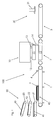
- the short-cycle press comprises means for position assurance, which are formed in the form of a strip-shaped press stop 14 which is pivotally mounted on the short-cycle press 10. If pressed material 40 is to be received, the press stop 14 is pivoted downwards and the upper press plate 11 is moved upwards. This condition is in Fig. 1 shown.
- the pressed material 40 is moved by means of the press conveyor belt 2 within 4 seconds in the space between the press plates 11,12. Then the press conveyor belt 2 stops and the pressed material 40 is secured by the stop 14 against displacement. Thereafter, the press stop 14 pivots upward while the upper press plate 11 is lowered within 0.5 seconds. This condition is in Fig. 2 shown. Under the influence of a pressure of 40 bar and a temperature of 220 ° C, the overlay and the liquid counter-pull with the wood-based panel 41 are pressed. The duration of the pressing process is 7 seconds. Subsequently, the upper press plate 11 is raised within 0.5 seconds and the pressed material 40 is discharged by means of the press conveyor belt 2 within 4 seconds from the press, while new pressed material is entered into the short-cycle press 10.
- the press conveyor belt 2 moves the pressed material 40 to the removal conveyor belt 3 made of BOPET, which moves the pressed material 40 to a removal station 30.
- the pressed material 40 is lifted by means of a siphon 31 from the removal conveyor belt 3.
- the total charging time is 6 seconds.
- the charging time is so short because, in contrast to prior art systems in which the pressed material is discharged into the press and lifted out again after pressing, in the present invention loading, pressing and discharging occur in one plane. Furthermore, eliminates the handling of the feeders before pressing. Finally, is reduced by the fact that the retracted into the press package only the height of the pressed material, the stroke of the upper press plate, and thus the time for the process of the press plate.
Landscapes
- Life Sciences & Earth Sciences (AREA)
- Engineering & Computer Science (AREA)
- Wood Science & Technology (AREA)
- Manufacturing & Machinery (AREA)
- Forests & Forestry (AREA)
- Mechanical Engineering (AREA)
- Dry Formation Of Fiberboard And The Like (AREA)
- Veneer Processing And Manufacture Of Plywood (AREA)
- Chemical And Physical Treatments For Wood And The Like (AREA)
Abstract
Description
Die Erfindung betrifft ein Verfahren zum Aufpressen einer mindestens einlagigen Oberflächenbeschichtung auf eine Holzwerkstoffplatte, wobei die Holzwerkstoffplatte eine unterseitig aufgetragenen, getrocknete, nicht-ausgehärtete, duroplastische Kunstharzschicht aufweist, in einer Kurztaktpresse, die eine obere und eine untere beheizbare Preßplatte sowie eine Beschickvorrichtung umfaßt. Weiterhin betrifft die Erfindung eine Beschickvorrichtung für eine Kurztaktpresse sowie eine Kurztaktpresse.The invention relates to a method for pressing a at least single-layer surface coating on a wood-based panel, wherein the wood-based panel has a bottom applied, dried, non-cured, thermosetting resin layer, in a short-cycle press comprising an upper and a lower heatable press plate and a feeder. Furthermore, the invention relates to a feeder for a short-cycle press and a short-cycle press.
Holzwerkstoffplatten umfassen alle Werkstoffe, die aus Holz oder überwiegend aus Holz bestehen und die in verarbeiteter Form plattenförmig vorliegen. Holzwerkstoffplatten können aus Furnier unterschiedlicher Stärke, sowie aus Leisten, Holzfasern oder einer Kombination hieraus hergestellt sein.Wood-based panels include all materials that are made of wood or predominantly of wood and that are in plate form in processed form. Wood-based panels can be made of veneer of different thickness, as well as strips, wood fibers or a combination thereof.
Holzwerkstoffplatten werden für verschiedene Anwendungen beschichtet. Dies geschieht um der Oberfläche ein bestimmtes Aussehen zu geben und/oder um die Oberfläche unempfindlicher gegen bestimmte Belastungen zu machen.Wood-based panels are coated for various applications. This is done to give the surface a certain look and / or to make the surface less sensitive to certain loads.
Im Sinne der erstgenannten Anforderung wird die Platte mit einem Dekor versehen, das entweder aufgestrichen, aufgesprüht, aufgedruckt oder in Form eines bedruckten Papiers aufgebracht wird. Die Dekorschicht muß in der Regel durch eine zusätzliche Beschichtung geschützt werden. Dies kann durch ein Overlay geschehen, ein mit duroplastischem Kunstharz getränktes, durchsichtiges Papier. Die verwendeten duroplastischen Kunstharze weisen in ausgehärtetem Zustand eine gute Verschleißfestigkeit auf, die bei Bedarf durch Zusätze, wie z. B. Korund-Partikel, noch erhöht werden kann.For the purpose of the first-mentioned requirement, the plate is provided with a decor which is either painted on, sprayed on, printed or applied in the form of a printed paper. The decorative layer must be protected by an additional coating usually. This can be done through an overlay, a soaked with thermosetting resin, transparent paper. The thermosetting resins used in the cured state have a good resistance to wear, which, if necessary, by additives such. B. corundum particles, can still be increased.
Duroplastische Kunstharze, wie Phenolharze, Melamin und/oder Harnstoffharze, können flüssig verarbeitet und vorgetrocknet werden, härten jedoch nur beim gleichzeitigen Einwirken von Druck (ca. 20-40 bar) und Hitze (z. B. 180°C) aus. In der industriellen Fertigung geschieht dies in einer beheizten Presse, die das Overlay (und das Dekor) mit der Holzwerkstoffplatte verpresst. Diese Kunstharze haben die unerwünschte Eigenschaft, daß sie während des Aushärtens einer Schrumpfung unterliegen, was beim Verpressen mit der Oberfläche der Platte zu Spannungen führt, die die Platte verformen und somit unbrauchbar machen.Thermosetting synthetic resins, such as phenolic resins, melamine and / or urea resins, can processed liquid and pre-dried, but cure only with the simultaneous action of pressure (about 20-40 bar) and heat (eg., 180 ° C). In industrial production, this is done in a heated press, which presses the overlay (and the decor) with the wood-based panel. These synthetic resins have the undesirable property of undergoing shrinkage during curing, resulting in stresses when pressed against the surface of the plate which deform the plate and thus render it useless.
Um diesem Effekt entgegenzuwirken, verwendet man einen Gegenzug, typischerweise in Form eines in Kunstharz getränkten Papiers, ähnlich dem Overlay, das auf die gegenüberliegende Seite der Platte aufgebracht wird. Hierdurch wird erreicht, daß sich die Spannungen auf Ober- und Unterseite gegenseitig ausgleichen.To counteract this effect, one uses a counter-pull, typically in the form of a resin impregnated paper, similar to the overlay applied to the opposite side of the plate. This ensures that compensate for the stresses on the top and bottom of each other.
Um ebene, beschichtete Paletten herzustellen, müssen also nach dem Stand der Technik, z.B.
Nach dem Stand der Technik wird das Paket mittels einer Beschickvorrichtung gesichert, die die Schichten des Pakets aufeinander auf längsseitig angeordnete Leisten auflegt, gegebenenfalls auf diese Leisten klemmt und die Rahmen mit den Paketen anschließend in die Presse transportiert. Die Leisten müssen vor dem eigentlichen Preßvorgang entfernt und zurückgeführt werden. Der hohe Aufwand bei der Handhabung der Beschickvorrichtung führt zu langen Taktzeiten und setzt die Wirtschaftlichkeit des Verfahrens herab.According to the prior art, the package is secured by means of a loading device which hangs up the layers of the package on longitudinally arranged strips, optionally clamped on these strips and then transported the frame with the packages in the press. The strips must be removed and returned before the actual pressing process. The high cost of handling the feeder leads to long cycle times and reduces the cost of the process.
Zum Verpressen des Pakets werden typischerweise Kurztaktpressen verwendet, die sich durch vergleichsweise kurze Presszeiten (ca. 10 Sekunden) auszeichnen. Eine solche Presse zum Aufpressen von Beschichtungen, die duroplastisches Kunstharz enthalten, benötigt als funktionelle Teile zwei Preßplatten, die beheizbar sind, und die mit hohem Druck gegeneinander gepreßt werden können.For pressing the package typically short-cycle presses are used, which are characterized by comparatively short pressing times (about 10 seconds). Such a press for pressing coatings containing thermosetting resin requires as functional parts, two press plates, which are heatable, and which can be pressed against each other with high pressure.
Beim derzeitigen Stand der Technik kann der Zeitaufwand für das Beschicken und Entleeren der Pressen mit den zur Verfügung stehenden technischen Mitteln nicht mehr wesentlich verkürzt werden. Somit ist es Aufgabe der vorliegenden Erfindung, die Chargierzeit zu verkürzen. Als Chargierzeit wird hier und im Folgenden die Zeit bezeichnet, die zwischen dem Ende eines Pressvorgangs, gekennzeichnet durch das Abheben der Preßplatten von der Holzwerkstoffplatte, und dem Beginn des nächsten Preßvorgangs, gekennzeichnet durch das Aufsetzen der Preßplatten, vergeht. Dieser Zeitraum umfaßt das Verfahren der Preßplatten, das Austragen der verpressten Holzwerkstoffplatte sowie das Einfahren der nächsten Holzwerkstoffplatte.In the current state of the art, the time required for loading and unloading the presses can no longer be significantly reduced with the available technical means. Thus, it is an object of the present invention to shorten the charging time. The term "charging time" here and hereinafter refers to the time which elapses between the end of a pressing operation, characterized by the lifting off of the pressing plates from the wood-based panel, and the beginning of the next pressing operation, characterized by the placement of the pressing plates. This period includes the process of press plates, the discharge of the compressed wood-based panel and the retraction of the next wood-based panel.
Die Aufgabe wird gelöst durch ein Verfahren nach Anspruch 1. Bei diesem Verfahren zum Aufpressen einer mindestens einlagigen Oberflächenbeschichtung auf eine Holzwerkstoffplatte in einer Kurztaktpresse, die eine obere und eine untere beheizbare Preßplatte sowie eine Beschickvorrichtung umfaßt, wird mittels der Beschickvorrichtung wenigstens eine Lage eines Beschichtungsmaterials auf der Oberseite der Holzwerkstoffplatte, die eine unterseitig aufgetragene, getrocknete, nicht-ausgehärtete, duroplastische Kunstharzschicht aufweist, positioniert und in einer definierten Position gehalten. Dann wird die Holzwerkstoffplatte in den Raum zwischen den Preßplatten eingebracht und anschließend wird die Oberflächenbeschichtung mit der Holzwerkstoffplatte verpresst. Abschließend wird die beschichtete Holzwerkstoffplatte ausgetragen.The object is achieved by a method according to
Die Aufgabe wird weiter gelöst durch eine Beschickvorrichtung für eine Kurztaktpresse nach Anspruch 9. Diese umfaßt erfindungsgemäß ein Förderband, das eine Kurztaktpresse durchläuft, wobei im Betriebszustand eine Holzwerkstoffplatte und wenigstens eine Lage eines Beschichtungsmaterials auf dem Förderband aufliegen und dort durch Mittel zur Positionssicherung gegen Positionsveränderungen gesichert sind.The object is further achieved by a loading device for a short-cycle press according to claim 9. This comprises a conveyor belt according to the invention, which passes through a short-cycle press, wherein in the operating state a wood-based panel and at least one layer of coating material rest on the conveyor belt and secured there by means for securing position position position changes are.
Schließlich wird die Aufgabe gelöst durch eine Kurztaktpresse nach Anspruch 22, die dadurch gekennzeichnet ist, daß diese eine Beschickvorrichtung gemäß einem der Ansprüche 9 bis 21 umfaßt.Finally, the object is achieved by a short-cycle press according to
Die Preßplatten der verwendeten Kurztaktpresse können grundsätzlich verschieden angeordnet sein. Bevorzugt ist bei der vorliegenden Erfindung eine Anordnung der Platten übereinander, wobei die untere Platte während des Pressens stationär bleibt, während die obere Platte abgesenkt wird. Vereinfachend werden die Preßplatten im Folgenden als "untere" und "obere" Platte bezeichnet, wodurch andere Ausführungsformen der Erfindung jedoch nicht ausgeschlossen werden sollen.The press plates of the short-cycle press used can basically be arranged differently. Preferably, in the present invention, an arrangement of the plates is one above the other, wherein the lower plate remains stationary during the pressing while the upper plate is lowered. For simplicity, the press plates are hereinafter referred to as "lower" and "upper" plate, whereby other embodiments of the invention, however, should not be excluded.
In einer bevorzugten Ausführung des Verfahrens besteht der flüssige Gegenzug aus Melamin, einem Phenolharz und/oder einem Harnstoffharz, da sich diese Harze durch zahlreiche vorteilhaften Materialeigenschaften und niedrige Materialkosten auszeichnen. Der flüssige Gegenzug wird auf der Unterseite der Holzwerkstoffplatte aufgetragen und getrocknet, aber nicht ausgehärtet. Dadurch kann die Holzwerkstoffplatte problemlos manipuliert werden, ohne daß ein separater Gegenzug zu handhaben ist. Ein Verrutschen der Platte auf dem Gegenzug ist ausgeschlossen.In a preferred embodiment of the method, the liquid countermix is melamine, a phenolic resin and / or a urea resin, since these resins are distinguished by numerous advantageous material properties and low material costs. The liquid backing is applied to the underside of the wood-based panel and dried, but not cured. As a result, the wood-based panel can be easily manipulated without a separate counter-pull is to handle. Slipping of the plate on the return is excluded.
In Übereinstimmung mit dem Aufbau der Oberflächenbeschichtung, der aus herkömmlichen Verfahren bekannt ist, besteht beim erfindungsgemäßen Verfahren die Oberflächenbeschichtung bevorzugt aus zwei oder mehr Lagen. Dies ermöglicht eine flexiblere Gestaltung der Oberfläche. So kann man z.B. das attraktive Aussehen einer oder mehrerer Dekorschichten mit der Robustheit einer darüber angeordneten Schicht aus abriebfestem Lack oder Harz kombinieren.In accordance with the structure of the surface coating known from conventional methods, in the method according to the invention, the surface coating preferably consists of two or more layers. This allows a more flexible design of the surface. So you can, for example Combine the attractive appearance of one or more decorative layers with the robustness of an overlying layer of abrasion resistant paint or resin.
Bei Verwendung einer mit einem flüssigen aufgetragenen, getrockneten, aber nicht ausgehärtetem Gegenzug beschichteten Holzwerkstoffplatte kann auf einen aufwendigen Fixiermechanismus verzichtet werden, da die Fixierung eines separaten unterseitigen Gegenzugs an der Holzwerkstoffplatte entfällt. Die Platte, die die stabilste Schicht des Preßgutpakets darstellt, bildet nunmehr die unterste Lage, was erheblich zur Vereinfachung des Fixiervorgangs beiträgt. Somit müssen die einzelnen Pakete nicht mehr mit einer aufwendigen Beschickvorrichtung und Entleervorrichtung in die Presse und aus der Presse transportiert werden. Erfindungsgemäß genügt hier ein Anschlag, der in ein Förderband integriert werden kann, das in die Presse führt. Als Anschlag wird in diesem Zusammenhang jede Art von Vorrichtung bezeichnet, die das Preßgut in wenigstens einer Richtung gegen horizontale Positionsveränderung sichert. In einer besonderen Ausführungsform der Erfindung wird jeweils ein Anschlag durch Leisten gebildet, die quer zur Laufrichtung des Förderbandes ausgerichtet sind. In einer Weiterbildung der Erfindung weist das Förderband mehrere Anschläge auf.When using a coated with a liquid, dried, but not cured counter-coated wood-based panel can be dispensed with a complex fixing mechanism, since the fixation of a separate underside counter-contact on the wood-based panel deleted. The plate, which represents the most stable layer of Preßgutpakets, now forms the bottom layer, which significantly contributes to the simplification of the fixing process. Thus, the individual packages no longer have to an elaborate feeder and emptying in the press and transported from the press. According to the invention, a stopper that can be integrated in a conveyor belt that leads into the press is sufficient here. As a stop, any type of device is referred to in this context, which secures the pressed material in at least one direction against horizontal position change. In a particular embodiment of the invention, a respective stop is formed by strips, which are aligned transversely to the direction of the conveyor belt. In a development of the invention, the conveyor belt has several stops.
In einer weiteren Ausführungsform der Erfindung sind Mittel zur Positionssicherung einer Holzwerkstoffplatte an oder in der Kurztaktpresse angeordnet. Dies bietet den großen Vorteil, daß auch bei einer nicht exakten Positionierung des Förderbandes die Holzwerkstoffplatte in Bezug auf die Kurztaktpresse richtig positioniert wird. Es kann sich bei dieser Ausführung z. B. um verschiebliche Leisten handeln, die beim Ausrichten der Holzwerkstoffplatte und der Oberflächenbeschichtung als Anschlag dienen, die aber beim Fördern der Platte oder beim Zusammenfahren der Presse verschoben werden.In a further embodiment of the invention, means for securing the position of a wood-based panel are arranged on or in the short-cycle press. This offers the great advantage that even with a non-exact positioning of the conveyor belt, the wood-based panel is correctly positioned with respect to the short-cycle press. It may be in this embodiment z. B. act on slidable strips that serve as a stop when aligning the wood-based panel and the surface coating, but which are moved when conveying the plate or when moving the press.
Das Förderband läuft über die untere Preßplatte, so daß mittels des Bandes das Preßgut zwischen die beiden Preßplatten eingebracht werden kann, und läuft unterhalb der Preßplatte zurück. Da das Förderband sich während des Pressens zwischen der unteren beheizbaren Platte und dem Preßgut befindet, muß dieses zum einen beständig gegenüber den hierbei typischerweise auftretenden Temperaturen sein, also wenigstens bis 200°C, bevorzugt bis wenigstens 250°C, besonders bevorzugt bis wenigstens 280°C, zum anderen sollte es eine hinreichend hohe Wärmeleitfähigkeit aufweisen, um nicht das Aufheizen des Preßguts zu verzögern. Die Wärmeleitfähigkeit sollte über 5 JK-1m-1s-1 liegen, was z.B. für sämtliche metallischen Werkstoffe erfüllt ist. Bevorzugt ist eine Wärmeleitfähigkeit von über 20 JK-1m-1s-1, weiter bevorzugt über 150 JK-1m-1s-1.The conveyor belt runs over the lower press plate, so that by means of the belt, the pressed material can be introduced between the two press plates, and runs back below the press plate. Since the conveyor belt is located between the lower heatable plate and the pressed material during pressing, it must be resistant to the typically occurring temperatures, ie at least 200 ° C., preferably at least 250 ° C., more preferably at least 280 ° C, on the other hand, it should have a sufficiently high thermal conductivity, so as not to delay the heating of the pressed material. The thermal conductivity should be above 5 JK -1 m -1 s -1 , which is fulfilled, for example, for all metallic materials. Preference is given to a thermal conductivity of more than 20 JK -1 m -1 s -1 , more preferably more than 150 JK -1 m -1 s -1 .
Eine weitere Anforderung an das Förderband ist, daß keinerlei Rückstände von unausgehärtetem oder ausgehärtetem Kunstharz daran haften. Um dieser Anforderung sowie der nach Hitzebeständigkeit und allgemeiner Robustheit nachzukommen, besteht in einer bevorzugten Ausführungsform der Erfindung das Förderband aus Aramid und ist mit Polytetrafluoroethylen beschichtet.Another requirement of the conveyor belt is that no residue of uncured or cured synthetic resin adhere thereto. In order to meet this requirement as well as for heat resistance and general robustness, in a preferred embodiment of the invention, the conveyor belt is made of aramid and is coated with polytetrafluoroethylene.
Da beim erfindungsgemäßen Verfahren auf aufwendige Fixiervorrichtungen, die nach dem Stand der Technik einige Tonnen wiegen, verzichtet werden kann, ist die notwendige Leistungsaufnahme der Beschickvorrichtung drastisch reduziert. Sie beträgt in einer Weiterbildung der Erfindung unter 40 kW, bevorzugt unter 30 kW, besonders bevorzugt unter 20 kW.Since in the method according to the invention can be dispensed with complex fixing devices that weigh several tons in the prior art, the necessary power consumption of the feeder is drastically reduced. It is in a further development of the invention below 40 kW, preferably below 30 kW, more preferably below 20 kW.
Nach dem Verpressen und Austragen der Platten aus der Presse ist es notwendig, diese zur Weiterverarbeitung, Verpackung, Lagerung etc. vom Förderband zu entfernen. Zu diesem Zweck umfaßt in einer bevorzugten Ausführungsform der Erfindung die Beschickvorrichtung eine Vorrichtung zur Abnahme der verpressten Materialien. Diese kann z. B. die Platten mittels Saughebern manipulieren, es sind aber auch andere Mechanismen möglich.After pressing and discharging the plates from the press, it is necessary to remove them from the conveyor belt for further processing, packaging, storage etc. For this purpose, in a preferred embodiment of the invention, the loading device comprises a device for removing the compressed materials. This can, for. B. manipulate the plates by means of suction lifters, but other mechanisms are possible.
Der Transport des Preßguts bzw. der beschichteten Platten zwischen Auf- und Abnahme kann mittels eines oder mehrerer Förderbänder erfolgen. Verschiedene Varianten sind denkbar.The transport of the pressed material or the coated plates between acceptance and removal can be done by means of one or more conveyor belts. Different variants are conceivable.
In einer Ausführungsform der Erfindung umfaßt die Beschickvorrichtung ein Förderband, das in eine Beschickstation, die Kurztaktpresse sowie eine Abnahmestation durchläuft. Diese Ausführung gewährleistet eine sichere Positionierung der Platten beim Beschicken, Pressen und Abnehmen. Des weiteren benötigt man nur einen Antrieb, wodurch sich geringe Betriebs- und Wartungskosten ergeben.In one embodiment of the invention, the loading device comprises a conveyor belt which passes into a loading station, the short-cycle press and a removal station. This design ensures a safe positioning of the plates during loading, pressing and removal. Furthermore, you only need a drive, resulting in low operating and maintenance costs.
In einer alternativen Ausführungsform der Erfindung umfaßt die Beschickvorrichtung ein erstes Förderband, das die Beschickstation und die Kurztaktpresse durchläuft, sowie ein zweites Förderband, das an das erste Förderband anschließend angeordnet ist und die Abnahmestation durchläuft. Hierbei kann für das zweite Förderband ein anderes Material gewählt werden als für das erste, da das zweite Band nicht den hohen Temperaturen des Preßvorgangs ausgesetzt ist. Gegebenenfalls kann beim zweiten Band auch auf Mittel zur Positionssicherung verzichtet werden und es kann mit höheren Beschleunigungen arbeiten, da hier die exakte Positionierung der Platten nicht kritisch ist. Somit können Zeit und Kosten eingespart werden.In an alternative embodiment of the invention, the loading device comprises a first conveyor belt which passes through the loading station and the short-cycle press, and a second conveyor belt, which is subsequently arranged on the first conveyor belt and passes through the removal station. In this case, a different material can be selected for the second conveyor belt than for the first, since the second belt is not exposed to the high temperatures of the pressing operation. Optionally, can be dispensed with means for position assurance in the second band and it can work with higher accelerations, since the exact positioning of the plates is not critical. Thus, time and can Cost savings.
In einer weiteren Ausführungsform der Erfindung umfaßt die Beschickvorrichtung ein erstes Förderband, das die Beschickstation durchläuft, sowie ein zweites Förderband, das an das erste Förderband anschließend angeordnet ist und das die Kurztaktpresse sowie die Abnahmestation durchläuft. Bei dieser Ausführung kann das erste Förderband aus einem Material bestehen, das keine besondere Temperaturbeständigkeit oder Wärmeleitfähigkeit aufweist, da es am Preßvorgang nicht beteiligt ist. Dies ermöglicht die Wahl eines Materials, das z. B. preiswert und/oder leicht ist.In a further embodiment of the invention, the loading device comprises a first conveyor belt which passes through the loading station and a second conveyor belt which is subsequently arranged on the first conveyor belt and which passes through the short-cycle press and the removal station. In this embodiment, the first conveyor belt may be made of a material having no particular temperature resistance or thermal conductivity because it is not involved in the pressing operation. This allows the choice of a material that z. B. is inexpensive and / or easy.
In einer weiteren Ausführungsform der Erfindung umfaßt die Beschickvorrichtung ein erstes Förderband, das die Beschickstation durchläuft, sowie ein zweites Förderband, das an das erste Förderband anschließend angeordnet ist und die Kurztaktpresse durchläuft, sowie ein drittes Förderband, das an das zweite Förderband anschließend angeordnet ist und die Abnahmestation durchläuft. In dieser Ausführung können Vorteile bereits beschriebener Ausführungen kombiniert werden. So kann z. B. für das erste Förderband ein preiswertes Material gewählt werden, während man beim dritten Band auf Mittel zur Positionssicherung verzichten kann.In a further embodiment of the invention, the loading device comprises a first conveyor belt which passes through the loading station and a second conveyor belt which is subsequently arranged on the first conveyor belt and passes through the short-cycle press and a third conveyor belt which is subsequently arranged on the second conveyor belt and passes through the removal station. In this embodiment, advantages of already described embodiments can be combined. So z. B. for the first conveyor an inexpensive material can be selected, while you can do without the third band on means for position assurance.
Durch das vereinfachte Beschickverfahren liegt bei der vorliegenden Erfindung die Chargierzeit unter 8 Sekunden, bevorzugt unter 7 Sekunden. Chargierzeiten von 5-6 Sekunden sind möglich. Dieser Wert liegt unter den nach dem Stand der Technik typischen von ca. 8-12 Sekunden.Due to the simplified feed method, the charging time in the present invention is less than 8 seconds, preferably less than 7 seconds. Charging times of 5-6 seconds are possible. This value is below the state of the art typical of about 8-12 seconds.
Auch die Preßzeit läßt sich verkürzen, da wegen des vereinfachten Beschickvorgangs die kritische Liegezeit, also die Zeit vom Beginn des Einbringens des Paketes in die Presse bis zum Verpressen verkürzt wird. Bei Vorrichtungen nach dem Stand der Technik beeinflußt die kritische Liegezeit auch die Preßzeit, da innerhalb der Liegezeit ein unerwünschtes vorzeitiges Aushärten des duroplastischen Kunstharzes erfolgen kann. Eine solche vorzeitig ausgehärtete Harzschicht ist unbrauchbar. Da das Aushärten um so schneller erfolgt, je höher die Temperatur ist, muß die Temperatur während der kritischen Liegezeit unter einem bestimmten Wert gehalten werden, womit im Wesentlichen auch die Temperatur für den Preßvorgang vorgegeben ist, da eine Veränderung innerhalb der kurzen Taktzeiten praktisch nicht möglich ist. Somit ist aber auch die Preßzeit nach unten begrenzt. Beim erfindungsgemäßen Verfahren kann die kritische Liegezeit deutlich reduziert werden, da zum einen das Entfernen der Rahmen entfällt, zum anderen durch das Fehlen derselben das in die Presse einzubringende Paket niedriger ist und somit der Hubweg der oberen Preßplatte zwischen geöffneter und geschlossener Position kleiner. Daher kann auch das Schließen schneller erfolgen. Dank der kürzeren Liegezeit liegt die Temperatur der Preßplatten beim vorliegenden Verfahren bei mindestens 180°C, bevorzugt mindestens 220°C, weiter bevorzugt mindestens 250°C, wodurch sich die Preßzeit auf unter 10 Sekunden, bevorzugt unter 8 Sekunden, besonders bevorzugt unter 7 Sekunden, senken läßt.Also, the pressing time can be shortened because of the simplified loading process, the critical time, ie the time from the beginning of the introduction of the package in the press is reduced to the pressing. In devices according to the prior art, the critical time also affects the pressing time, since an unwanted premature curing of the thermosetting resin can take place during the lying time. Such a prematurely cured resin layer is unusable. Since the curing is faster, the higher the temperature, the temperature must be kept below a certain value during the critical time, which is essentially the temperature for the pressing process is given, as a change within the short cycle times is practically impossible. Thus, however, the pressing time is limited down. In the method according to the invention, the critical lying time can be significantly reduced, on the one hand eliminates the removal of the frame, on the other hand by the absence of the same introduced into the press package is lower and thus the stroke of the upper press plate between the open and closed position smaller. Therefore, the closing can be done faster. Thanks to the shorter lay time, the temperature of the press plates in the present process is at least 180 ° C, preferably at least 220 ° C, more preferably at least 250 ° C, whereby the pressing time to less than 10 seconds, preferably less than 8 seconds, more preferably less than 7 seconds , lower.
In einer bevorzugten Ausführung des Verfahrens ist die Chargierzeit nicht größer als die Preßzeit. Dies stellt gegenüber Verfahren nach dem Stand der Technik einen wichtigen Fortschritt dar, da bei diesen das Chargieren, das nur der Vorbereitung der eigentlichen Verarbeitung dient, den Hauptteil der Taktzeit einnimmt und somit die Presse als teuerster Anlagenteil überwiegend im Leerlauf arbeitet. Somit wird die Wirtschaftlichkeit durch das neue Verfahren deutlich erhöht.In a preferred embodiment of the method, the charging time is not greater than the pressing time. This represents an important advance over prior art methods, since in them the charging, which only serves to prepare the actual processing, occupies the major part of the cycle time and thus the press operates as the most expensive part of the system predominantly idling. Thus, the efficiency is significantly increased by the new process.
Die Vorteile der vorliegenden Erfindung liegen zum einen in der kürzeren Taktzeit, bedingt durch die kürzere Beschick- sowie Preßzeit. Hierdurch wird eine höhere Produktivität der Anlage erreicht. Da die schweren Beschickvorrichtungen und Entleervorrichtungen entfallen, kann die Anlage mit weniger Leistung betrieben werden. Auch werden die Kosten für Anschaffung, Wartung und Instandsetzung der Leisten zum Sichern der Preßgutpakete eingespart. Da die Beschickvorrichtung nur noch geringe Lasten bewegen muß, unterliegt sie weniger Verschleiß. Der Rückführungsprozeß für die Leisten entfällt, womit Energie, Kosten und Platz eingespart werden.The advantages of the present invention are on the one hand in the shorter cycle time, due to the shorter loading and pressing time. As a result, a higher productivity of the system is achieved. Since the heavy loaders and emptying omitted, the system can be operated with less power. Also, the cost of purchase, maintenance and repair of the strips to secure the Preßgutpakete be saved. Since the feeder only has to move small loads, it is subject to less wear. The return process for the strips is eliminated, thus saving energy, costs and space.
Im Folgenden wird die Funktion der Erfindung anhand von Abbildungen erläutert. Hierbei zeigt
- Fig. 1:
- Eine Seitenansicht einer Schnittzeichnung einer Ausführungsform der Beschickvorrichtung für eine Kurztaktpresse vor dem Preßvorgang
- Fig. 2:
- Eine Seitenansicht einer Schnittzeichnung der Ausführungsform der Beschickvorrichtung für eine Kurztaktpresse aus
Fig.1 während des Preßvorgangs - Fig. 3:
- Eine Seitenansicht einer Schnittzeichnung der Ausführungsform der Beschickvorrichtung für eine Kurztaktpresse aus
Fig.1 nach dem Preßvorgang
- Fig. 1:
- A side view of a sectional drawing of an embodiment of the charging device for a short-cycle press before the pressing process
- Fig. 2:
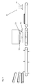
- A side view of a sectional drawing of the embodiment of the charging device for a short-cycle press
Fig.1 during the pressing process - 3:
- A side view of a sectional drawing of the embodiment of the charging device for a short-cycle press
Fig.1 after the pressing process
Bei der in
Im Betrieb werden in einer Beschickstation 20 mittels eines ersten, zweiten und dritten Zuführförderbandes 21, 22, 23 eine Holzwerkstoffplatte 41 mit unterseitig angebrachtem flüssigen Gegenzug, ein Dekorpapier 42 und ein Overlay 43 auf dem aus Polyethylenterephthalat-Polyesterfolie (BOPET) gefertigten Beschickförderband 1 platziert. Die Holzwerkstoffplatte 41 wird auf dem Beschickförderband 1 abgelegt und auf dieser werden wiederum das Dekorpapier 42 und anschließend das Overlay 43 abgelegt und so zu einem Preßgutpaket 40 zusammengefaßt. Durch eine Reihe von Beschickanschlägen 4, die auf dem Beschickförderband 1 angeordnet sind, wird das Preßgut 40, bestehend aus Holzwerkstoffplatte 41, Dekorpapier 42 und Overlay 43, dort gegen Positionsveränderungen gesichert.In operation, in a
Das Preßgut 40 mit einer Fläche von 207 x 560 cm, das in unverpresstem Zustand eine Dicke von etwa 2 cm aufweist, wird mittels des Beschickförderbands 1 in Richtung des Pressenförderbandes 2 verfahren. Das Pressenförderband 2 ist zur höheren Temperaturbeständigkeit aus Aramid gefertigt und mit Polytetrafluoroethylen beschichtet. Wenn das Preßgut 40 mit dem Pressenförderband 2 in Berührung kommt, läuft dieses mit einer Geschwindigkeit, die in etwa derjenigen des Beschickförderbands 1 entspricht, so daß Beschleunigungskräfte auf das Preßgut 40 vermieden werden. Anschließend wird das Preßgut 40 mittels des Pressenförderbandes 2 in die Kurztaktpresse 10 verfahren. Diese umfaßt eine untere Preßplatte 12 und eine obere Preßplatte 11, die durch Hubmittel 13 vertikal verfahren werden kann. Beide Preßplatten 11, 12 sind aus Stahl gefertigt und mittels Öl indirekt beheizbar. Die Fläche der Preßplatten 11, 12 beträgt 220 x 570 cm.The pressed
Die erfindungsgemäße Beschickvorrichtung erfordert keine separaten Mittel zum Fixieren des Preßguts von oben. Sie ist daher gegenüber Anlagen nach dem Stand der Technik sehr flach ausgelegt. Da allein die Dicke des zu Preßguts 40 zu berücksichtigen ist, beträgt der Hubweg der oberen Preßplatte 11 lediglich 6 cm, bezogen auf die Oberfläche des Pressenförderbandes 2. Das Pressenförderband 2 weist keine Anschläge zur Sicherung des Preßguts auf. Dafür umfaßt die Kurztaktpresse Mittel zur Positionssicherung, die in Form eines leistenförmigen Pressenanschlags 14 ausgebildet sind, der schwenkbar an der Kurztaktpresse 10 angeordnet ist. Soll Preßgut 40 aufgenommen werden, ist der Pressenanschlag 14 nach unten geschwenkt und die obere Preßplatte 11 ist nach oben verfahren. Dieser Zustand ist in
Das Preßgut 40 wird mittels des Pressenförderbandes 2 innerhalb von 4 Sekunden in den Raum zwischen den Preßplatten 11,12 verfahren. Dann stoppt das Pressenförderband 2 und das Preßgut 40 wird durch den Anschlag 14 gegen Verschiebungen gesichert. Danach schwenkt der Pressenanschlag 14 nach oben während die obere Preßplatte 11 innerhalb von 0.5 Sekunden abgesenkt wird. Dieser Zustand ist in
Das Pressenförderband 2 verfährt das Preßgut 40 zu dem aus BOPET gefertigten Abnahmeförderband 3, das das Preßgut 40 zu einer Abnahmestation 30 verfährt. Dies ist in
Da das Ein- und Austragen teilweise parallel verlaufen, beträgt die gesamte Chargierzeit 6 Sekunden. Die Chargierzeit ist deshalb so kurz, weil im Gegensatz zu Anlagen nach dem Stand der Technik, bei denen das Preßgut in die Presse abgelassen und nach dem Verpressen wieder herausgehoben wird, bei der vorliegenden Erfindung Beschicken, Verpressen und Austragen in einer Ebene ablaufen. Weiterhin entfällt die Handhabung der Beschickvorrichtungen vor dem Pressen. Schließlich ist durch die Tatsache, daß das in die Presse eingefahrene Paket nur noch die Höhe des Preßguts aufweist, der Hubweg der oberen Preßplatte verkürzt, und somit auch die Zeit für das Verfahren der Preßplatte. Since the feed and discharge are partially parallel, the total charging time is 6 seconds. The charging time is so short because, in contrast to prior art systems in which the pressed material is discharged into the press and lifted out again after pressing, in the present invention loading, pressing and discharging occur in one plane. Furthermore, eliminates the handling of the feeders before pressing. Finally, is reduced by the fact that the retracted into the press package only the height of the pressed material, the stroke of the upper press plate, and thus the time for the process of the press plate.
Claims (22)
Priority Applications (1)
| Application Number | Priority Date | Filing Date | Title |
|---|---|---|---|
| PL08015107T PL2030786T3 (en) | 2007-08-28 | 2008-08-27 | Method for pressing a surface coating of at least one layer onto a wood board and feeding device for a short cycle press |
Applications Claiming Priority (1)
| Application Number | Priority Date | Filing Date | Title |
|---|---|---|---|
| DE102007040805A DE102007040805B4 (en) | 2007-08-28 | 2007-08-28 | Process for pressing on at least one single-layer surface coating on a wood-based panel |
Publications (3)
| Publication Number | Publication Date |
|---|---|
| EP2030786A2 true EP2030786A2 (en) | 2009-03-04 |
| EP2030786A3 EP2030786A3 (en) | 2010-07-28 |
| EP2030786B1 EP2030786B1 (en) | 2012-12-12 |
Family
ID=40032677
Family Applications (1)
| Application Number | Title | Priority Date | Filing Date |
|---|---|---|---|
| EP08015107A Active EP2030786B1 (en) | 2007-08-28 | 2008-08-27 | Method for pressing a surface coating of at least one layer onto a wood board and feeding device for a short cycle press |
Country Status (5)
| Country | Link |
|---|---|
| EP (1) | EP2030786B1 (en) |
| DE (1) | DE102007040805B4 (en) |
| ES (1) | ES2400395T3 (en) |
| PL (1) | PL2030786T3 (en) |
| PT (1) | PT2030786E (en) |
Cited By (7)
| Publication number | Priority date | Publication date | Assignee | Title |
|---|---|---|---|---|
| BE1018632A3 (en) * | 2009-01-26 | 2011-05-03 | Flooring Ind Ltd Sarl | FLOOR PANEL, METHODS FOR MANUFACTURING LAMINATE PANELS AND METHOD FOR TREATING MATERIAL SHEETS USED HEREIN. |
| CN104227821A (en) * | 2014-09-28 | 2014-12-24 | 浙江瑞澄木业有限公司 | Feeding mechanism of reinforced floor board hot pressing device |
| EP3034259A1 (en) * | 2014-12-18 | 2016-06-22 | Flooring Technologies Ltd. | Method for manufacturing a wooden work surface with decorative panel, in particular a wood-plastic compound material with decorative panel |
| EP3290173A1 (en) * | 2016-09-02 | 2018-03-07 | SWISS KRONO Tec AG | Method for structuring the surface of a wooden panel and a surface-structured wooden panel prepared by means of this process |
| CN108547184A (en) * | 2018-05-07 | 2018-09-18 | 王月芳 | A kind of waste plant fiber production composite board device |
| US10369721B2 (en) | 2014-11-06 | 2019-08-06 | Flooring Technologies Ltd. | Wooden material panel, in particular in the form of a wood-plastic composite material, and a method for producing the same |
| CN115229934A (en) * | 2022-08-26 | 2022-10-25 | 豪德机械(上海)有限公司 | Automatic feeding device of edge bonding machine |
Citations (4)
| Publication number | Priority date | Publication date | Assignee | Title |
|---|---|---|---|---|
| DE2448356A1 (en) | 1974-10-10 | 1976-04-22 | Wemhoener Kg Heinrich | Flat workpieces laminating press - infeed conveyor in line with press conveyor and both controlled by clutches ensure continuous transport |
| DE2928231A1 (en) | 1979-07-12 | 1981-01-29 | Dieffenbacher Gmbh Maschf | Laminated material press system - lifts finished article by members inserted from sides and sets down on transporters |
| DE19718866A1 (en) | 1997-05-03 | 1998-11-05 | Dieffenbacher Gmbh Maschf | Method of feeding and removal of coated panels to and from short cycle coating press and process plant |
| DE10360187A1 (en) | 2003-12-20 | 2005-07-14 | Theodor Hymmen Holding Gmbh | Manufacture of coated wooden board for furniture, by printing colors onto board, coating with synthetic resin and embossing |
Family Cites Families (2)
| Publication number | Priority date | Publication date | Assignee | Title |
|---|---|---|---|---|
| AT333492B (en) * | 1973-12-21 | 1976-11-25 | Siempelkamp Gmbh & Co | METHOD OF LOADING PLATE PRESSES |
| DE19938568A1 (en) * | 1998-08-21 | 2000-03-23 | Ed Heckewerth Nachf Gmbh & Co | Squaring-up process for edges of coated boards etc., involving passing board in straight line through squaring-up point where milling cutters act on two edges |
-
2007
- 2007-08-28 DE DE102007040805A patent/DE102007040805B4/en not_active Expired - Fee Related
-
2008
- 2008-08-27 PL PL08015107T patent/PL2030786T3/en unknown
- 2008-08-27 EP EP08015107A patent/EP2030786B1/en active Active
- 2008-08-27 ES ES08015107T patent/ES2400395T3/en active Active
- 2008-08-27 PT PT80151079T patent/PT2030786E/en unknown
Patent Citations (4)
| Publication number | Priority date | Publication date | Assignee | Title |
|---|---|---|---|---|
| DE2448356A1 (en) | 1974-10-10 | 1976-04-22 | Wemhoener Kg Heinrich | Flat workpieces laminating press - infeed conveyor in line with press conveyor and both controlled by clutches ensure continuous transport |
| DE2928231A1 (en) | 1979-07-12 | 1981-01-29 | Dieffenbacher Gmbh Maschf | Laminated material press system - lifts finished article by members inserted from sides and sets down on transporters |
| DE19718866A1 (en) | 1997-05-03 | 1998-11-05 | Dieffenbacher Gmbh Maschf | Method of feeding and removal of coated panels to and from short cycle coating press and process plant |
| DE10360187A1 (en) | 2003-12-20 | 2005-07-14 | Theodor Hymmen Holding Gmbh | Manufacture of coated wooden board for furniture, by printing colors onto board, coating with synthetic resin and embossing |
Cited By (11)
| Publication number | Priority date | Publication date | Assignee | Title |
|---|---|---|---|---|
| BE1018632A3 (en) * | 2009-01-26 | 2011-05-03 | Flooring Ind Ltd Sarl | FLOOR PANEL, METHODS FOR MANUFACTURING LAMINATE PANELS AND METHOD FOR TREATING MATERIAL SHEETS USED HEREIN. |
| US9366034B2 (en) | 2009-01-26 | 2016-06-14 | Flooring Industries Limited, Sarl | Floor panel, methods for manufacturing laminate panels and method for treating material sheets applied herewith |
| US10000040B2 (en) | 2009-01-26 | 2018-06-19 | Flooring Industries Limited, Sarl | Floor panel, methods for manufacturing laminate panels and method for treating material sheets applied herewith |
| CN104227821A (en) * | 2014-09-28 | 2014-12-24 | 浙江瑞澄木业有限公司 | Feeding mechanism of reinforced floor board hot pressing device |
| CN104227821B (en) * | 2014-09-28 | 2016-02-17 | 浙江瑞澄木业有限公司 | A kind of feeding mechanism of consolidated floor hot-press arrangement |
| US10369721B2 (en) | 2014-11-06 | 2019-08-06 | Flooring Technologies Ltd. | Wooden material panel, in particular in the form of a wood-plastic composite material, and a method for producing the same |
| US11072087B2 (en) | 2014-11-06 | 2021-07-27 | Flooring Technologies Ltd. | Wooden material panel, in particular in the form of a wood-plastic composite material, and a method for producing the same |
| EP3034259A1 (en) * | 2014-12-18 | 2016-06-22 | Flooring Technologies Ltd. | Method for manufacturing a wooden work surface with decorative panel, in particular a wood-plastic compound material with decorative panel |
| EP3290173A1 (en) * | 2016-09-02 | 2018-03-07 | SWISS KRONO Tec AG | Method for structuring the surface of a wooden panel and a surface-structured wooden panel prepared by means of this process |
| CN108547184A (en) * | 2018-05-07 | 2018-09-18 | 王月芳 | A kind of waste plant fiber production composite board device |
| CN115229934A (en) * | 2022-08-26 | 2022-10-25 | 豪德机械(上海)有限公司 | Automatic feeding device of edge bonding machine |
Also Published As
| Publication number | Publication date |
|---|---|
| EP2030786B1 (en) | 2012-12-12 |
| DE102007040805A1 (en) | 2009-03-05 |
| PL2030786T3 (en) | 2013-05-31 |
| DE102007040805B4 (en) | 2013-10-31 |
| ES2400395T3 (en) | 2013-04-09 |
| PT2030786E (en) | 2013-03-05 |
| EP2030786A3 (en) | 2010-07-28 |
Similar Documents
| Publication | Publication Date | Title |
|---|---|---|
| EP2030786B1 (en) | Method for pressing a surface coating of at least one layer onto a wood board and feeding device for a short cycle press | |
| DE2217396C3 (en) | Device for loading and unloading plate presses | |
| DE2329267A1 (en) | METHOD AND DEVICE FOR FITTING FILMS AND CARRIER PLATES TO A PRESS UNIT | |
| DE3139581C2 (en) | ||
| AT511305A1 (en) | METAL COLLECTION STATION | |
| DE2852456C2 (en) | Device for on and off panels in the manufacture of laminated panels | |
| DE1484255A1 (en) | Method and device for the production of rough panels | |
| DE2605172A1 (en) | LAYING DEVICE FOR PRESS PACKAGES | |
| DE2928231A1 (en) | Laminated material press system - lifts finished article by members inserted from sides and sets down on transporters | |
| DE69023011T2 (en) | APPARATUS FOR COATING A SURFACE AND THE SIDE EDGES OF A WOODEN PANEL OR SIMILAR MATERIAL WITH A THERMOFORMABLE FILM. | |
| DE4216691A1 (en) | Equipment for surfacing e.g. chipboard with e.g. impregnated papers etc. - takes papers from vertically moved stacks above and below board, and holds them by suction bars inside rollers which press them against boards | |
| DE2226897C3 (en) | Forming and pressing line for the manufacture of chipboard | |
| DE102008024799B4 (en) | Pressing device and method for removing deposits on a pressing tool | |
| DE3703344C2 (en) | Device for changing the press plate in a hot press | |
| DE19914357C2 (en) | Foil laying system for at least covering the top of carrier plates with foils | |
| DE102005018087B4 (en) | Casting mold pallet and plant for the production of cast concrete | |
| DE2262052C3 (en) | Device for short-cycle presses for depositing pressed material | |
| DE2323227A1 (en) | DEVICE FOR INDEPENDENT LOADING OF MACHINE TOOLS | |
| DE102021004249A1 (en) | Device and method for discontinuously producing a laminate from a plurality of substrates | |
| DE102015103523A1 (en) | Method and installation for stacking veneers and / or destacking a stack of veneer packages | |
| DE2434934A1 (en) | Belt loading double daylight press for curing coated panels - to minimise cycle times and platen temp. fluctuations | |
| DE19812478C1 (en) | press for plywood floor tiles | |
| EP3383633B1 (en) | Method and device for producing a conveyor belt | |
| DE2334957C3 (en) | Process and system for the production of tempered wood-based panels | |
| DE2225165A1 (en) | PLANT FOR THE PRODUCTION OF LAMINATE PANELS |
Legal Events
| Date | Code | Title | Description |
|---|---|---|---|
| PUAI | Public reference made under article 153(3) epc to a published international application that has entered the european phase |
Free format text: ORIGINAL CODE: 0009012 |
|
| AK | Designated contracting states |
Kind code of ref document: A2 Designated state(s): AT BE BG CH CY CZ DE DK EE ES FI FR GB GR HR HU IE IS IT LI LT LU LV MC MT NL NO PL PT RO SE SI SK TR |
|
| AX | Request for extension of the european patent |
Extension state: AL BA MK RS |
|
| PUAL | Search report despatched |
Free format text: ORIGINAL CODE: 0009013 |
|
| AK | Designated contracting states |
Kind code of ref document: A3 Designated state(s): AT BE BG CH CY CZ DE DK EE ES FI FR GB GR HR HU IE IS IT LI LT LU LV MC MT NL NO PL PT RO SE SI SK TR |
|
| AX | Request for extension of the european patent |
Extension state: AL BA MK RS |
|
| 17P | Request for examination filed |
Effective date: 20101220 |
|
| AKX | Designation fees paid |
Designated state(s): AT BE BG CH CY CZ DE DK EE ES FI FR GB GR HR HU IE IS IT LI LT LU LV MC MT NL NO PL PT RO SE SI SK TR |
|
| GRAP | Despatch of communication of intention to grant a patent |
Free format text: ORIGINAL CODE: EPIDOSNIGR1 |
|
| RAP1 | Party data changed (applicant data changed or rights of an application transferred) |
Owner name: FLOORING TECHNOLOGIES LTD. |
|
| GRAS | Grant fee paid |
Free format text: ORIGINAL CODE: EPIDOSNIGR3 |
|
| GRAA | (expected) grant |
Free format text: ORIGINAL CODE: 0009210 |
|
| AK | Designated contracting states |
Kind code of ref document: B1 Designated state(s): AT BE BG CH CY CZ DE DK EE ES FI FR GB GR HR HU IE IS IT LI LT LU LV MC MT NL NO PL PT RO SE SI SK TR |
|
| REG | Reference to a national code |
Ref country code: GB Ref legal event code: FG4D Free format text: NOT ENGLISH |
|
| REG | Reference to a national code |
Ref country code: CH Ref legal event code: EP |
|
| REG | Reference to a national code |
Ref country code: AT Ref legal event code: REF Ref document number: 588126 Country of ref document: AT Kind code of ref document: T Effective date: 20121215 |
|
| REG | Reference to a national code |
Ref country code: IE Ref legal event code: FG4D Free format text: LANGUAGE OF EP DOCUMENT: GERMAN |
|
| REG | Reference to a national code |
Ref country code: DE Ref legal event code: R096 Ref document number: 502008008853 Country of ref document: DE Effective date: 20130207 |
|
| REG | Reference to a national code |
Ref country code: SE Ref legal event code: TRGR |
|
| REG | Reference to a national code |
Ref country code: PT Ref legal event code: SC4A Free format text: AVAILABILITY OF NATIONAL TRANSLATION Effective date: 20130225 |
|
| REG | Reference to a national code |
Ref country code: ES Ref legal event code: FG2A Ref document number: 2400395 Country of ref document: ES Kind code of ref document: T3 Effective date: 20130409 |
|
| REG | Reference to a national code |
Ref country code: NL Ref legal event code: T3 |
|
| PG25 | Lapsed in a contracting state [announced via postgrant information from national office to epo] |
Ref country code: NO Free format text: LAPSE BECAUSE OF FAILURE TO SUBMIT A TRANSLATION OF THE DESCRIPTION OR TO PAY THE FEE WITHIN THE PRESCRIBED TIME-LIMIT Effective date: 20130312 Ref country code: FI Free format text: LAPSE BECAUSE OF FAILURE TO SUBMIT A TRANSLATION OF THE DESCRIPTION OR TO PAY THE FEE WITHIN THE PRESCRIBED TIME-LIMIT Effective date: 20121212 Ref country code: LT Free format text: LAPSE BECAUSE OF FAILURE TO SUBMIT A TRANSLATION OF THE DESCRIPTION OR TO PAY THE FEE WITHIN THE PRESCRIBED TIME-LIMIT Effective date: 20121212 |
|
| REG | Reference to a national code |
Ref country code: SK Ref legal event code: T3 Ref document number: E 13559 Country of ref document: SK |
|
| REG | Reference to a national code |
Ref country code: LT Ref legal event code: MG4D |
|
| PG25 | Lapsed in a contracting state [announced via postgrant information from national office to epo] |
Ref country code: SI Free format text: LAPSE BECAUSE OF FAILURE TO SUBMIT A TRANSLATION OF THE DESCRIPTION OR TO PAY THE FEE WITHIN THE PRESCRIBED TIME-LIMIT Effective date: 20121212 Ref country code: LV Free format text: LAPSE BECAUSE OF FAILURE TO SUBMIT A TRANSLATION OF THE DESCRIPTION OR TO PAY THE FEE WITHIN THE PRESCRIBED TIME-LIMIT Effective date: 20121212 |
|
| REG | Reference to a national code |
Ref country code: PL Ref legal event code: T3 |
|
| PG25 | Lapsed in a contracting state [announced via postgrant information from national office to epo] |
Ref country code: BG Free format text: LAPSE BECAUSE OF FAILURE TO SUBMIT A TRANSLATION OF THE DESCRIPTION OR TO PAY THE FEE WITHIN THE PRESCRIBED TIME-LIMIT Effective date: 20130312 Ref country code: CZ Free format text: LAPSE BECAUSE OF FAILURE TO SUBMIT A TRANSLATION OF THE DESCRIPTION OR TO PAY THE FEE WITHIN THE PRESCRIBED TIME-LIMIT Effective date: 20121212 Ref country code: IS Free format text: LAPSE BECAUSE OF FAILURE TO SUBMIT A TRANSLATION OF THE DESCRIPTION OR TO PAY THE FEE WITHIN THE PRESCRIBED TIME-LIMIT Effective date: 20130412 Ref country code: EE Free format text: LAPSE BECAUSE OF FAILURE TO SUBMIT A TRANSLATION OF THE DESCRIPTION OR TO PAY THE FEE WITHIN THE PRESCRIBED TIME-LIMIT Effective date: 20121212 |
|
| PG25 | Lapsed in a contracting state [announced via postgrant information from national office to epo] |
Ref country code: RO Free format text: LAPSE BECAUSE OF FAILURE TO SUBMIT A TRANSLATION OF THE DESCRIPTION OR TO PAY THE FEE WITHIN THE PRESCRIBED TIME-LIMIT Effective date: 20121212 |
|
| PLBE | No opposition filed within time limit |
Free format text: ORIGINAL CODE: 0009261 |
|
| STAA | Information on the status of an ep patent application or granted ep patent |
Free format text: STATUS: NO OPPOSITION FILED WITHIN TIME LIMIT |
|
| PG25 | Lapsed in a contracting state [announced via postgrant information from national office to epo] |
Ref country code: DK Free format text: LAPSE BECAUSE OF FAILURE TO SUBMIT A TRANSLATION OF THE DESCRIPTION OR TO PAY THE FEE WITHIN THE PRESCRIBED TIME-LIMIT Effective date: 20121212 |
|
| 26N | No opposition filed |
Effective date: 20130913 |
|
| PG25 | Lapsed in a contracting state [announced via postgrant information from national office to epo] |
Ref country code: CY Free format text: LAPSE BECAUSE OF FAILURE TO SUBMIT A TRANSLATION OF THE DESCRIPTION OR TO PAY THE FEE WITHIN THE PRESCRIBED TIME-LIMIT Effective date: 20121212 Ref country code: HR Free format text: LAPSE BECAUSE OF FAILURE TO SUBMIT A TRANSLATION OF THE DESCRIPTION OR TO PAY THE FEE WITHIN THE PRESCRIBED TIME-LIMIT Effective date: 20121212 |
|
| REG | Reference to a national code |
Ref country code: DE Ref legal event code: R097 Ref document number: 502008008853 Country of ref document: DE Effective date: 20130913 |
|
| PG25 | Lapsed in a contracting state [announced via postgrant information from national office to epo] |
Ref country code: MC Free format text: LAPSE BECAUSE OF FAILURE TO SUBMIT A TRANSLATION OF THE DESCRIPTION OR TO PAY THE FEE WITHIN THE PRESCRIBED TIME-LIMIT Effective date: 20121212 |
|
| REG | Reference to a national code |
Ref country code: IE Ref legal event code: MM4A |
|
| PG25 | Lapsed in a contracting state [announced via postgrant information from national office to epo] |
Ref country code: IE Free format text: LAPSE BECAUSE OF NON-PAYMENT OF DUE FEES Effective date: 20130827 |
|
| PG25 | Lapsed in a contracting state [announced via postgrant information from national office to epo] |
Ref country code: MT Free format text: LAPSE BECAUSE OF FAILURE TO SUBMIT A TRANSLATION OF THE DESCRIPTION OR TO PAY THE FEE WITHIN THE PRESCRIBED TIME-LIMIT Effective date: 20121212 |
|
| PG25 | Lapsed in a contracting state [announced via postgrant information from national office to epo] |
Ref country code: LU Free format text: LAPSE BECAUSE OF NON-PAYMENT OF DUE FEES Effective date: 20130827 Ref country code: HU Free format text: LAPSE BECAUSE OF FAILURE TO SUBMIT A TRANSLATION OF THE DESCRIPTION OR TO PAY THE FEE WITHIN THE PRESCRIBED TIME-LIMIT; INVALID AB INITIO Effective date: 20080827 |
|
| PG25 | Lapsed in a contracting state [announced via postgrant information from national office to epo] |
Ref country code: GR Free format text: LAPSE BECAUSE OF NON-PAYMENT OF DUE FEES Effective date: 20121212 |
|
| REG | Reference to a national code |
Ref country code: FR Ref legal event code: PLFP Year of fee payment: 9 |
|
| REG | Reference to a national code |
Ref country code: CH Ref legal event code: PCOW Free format text: NEW ADDRESS: SMARTCITY MALTA SCM01 OFFICE 406 RICASOLI, KALKARA SCM1001 (MT) |
|
| REG | Reference to a national code |
Ref country code: DE Ref legal event code: R082 Ref document number: 502008008853 Country of ref document: DE Representative=s name: KALKOFF & PARTNER PATENTANWAELTE MBB, DE Ref country code: DE Ref legal event code: R082 Ref document number: 502008008853 Country of ref document: DE Representative=s name: KALKOFF & PARTNER PATENTANWAELTE, DE Ref country code: DE Ref legal event code: R081 Ref document number: 502008008853 Country of ref document: DE Owner name: FLOORING TECHNOLOGIES LTD., MT Free format text: FORMER OWNER: FLOORING TECHNOLOGIES LTD., PIETA, MT |
|
| REG | Reference to a national code |
Ref country code: SK Ref legal event code: TE4A Ref document number: E 13559 Country of ref document: SK Owner name: FLOORING TECHNOLOGIES LTD., KALKARA SCM 1001, MT Effective date: 20170710 |
|
| REG | Reference to a national code |
Ref country code: FR Ref legal event code: PLFP Year of fee payment: 10 |
|
| REG | Reference to a national code |
Ref country code: FR Ref legal event code: CA Effective date: 20171013 |
|
| REG | Reference to a national code |
Ref country code: FR Ref legal event code: PLFP Year of fee payment: 11 |
|
| PGFP | Annual fee paid to national office [announced via postgrant information from national office to epo] |
Ref country code: NL Payment date: 20210823 Year of fee payment: 14 |
|
| PGFP | Annual fee paid to national office [announced via postgrant information from national office to epo] |
Ref country code: IT Payment date: 20210831 Year of fee payment: 14 Ref country code: AT Payment date: 20210818 Year of fee payment: 14 |
|
| PGFP | Annual fee paid to national office [announced via postgrant information from national office to epo] |
Ref country code: CH Payment date: 20210824 Year of fee payment: 14 Ref country code: TR Payment date: 20210820 Year of fee payment: 14 Ref country code: SE Payment date: 20210823 Year of fee payment: 14 Ref country code: SK Payment date: 20210819 Year of fee payment: 14 Ref country code: ES Payment date: 20210917 Year of fee payment: 14 |
|
| PGFP | Annual fee paid to national office [announced via postgrant information from national office to epo] |
Ref country code: PT Payment date: 20210818 Year of fee payment: 14 |
|
| REG | Reference to a national code |
Ref country code: SE Ref legal event code: EUG |
|
| REG | Reference to a national code |
Ref country code: CH Ref legal event code: PL |
|
| REG | Reference to a national code |
Ref country code: NL Ref legal event code: MM Effective date: 20220901 |
|
| REG | Reference to a national code |
Ref country code: SK Ref legal event code: MM4A Ref document number: E 13559 Country of ref document: SK Effective date: 20220827 |
|
| REG | Reference to a national code |
Ref country code: AT Ref legal event code: MM01 Ref document number: 588126 Country of ref document: AT Kind code of ref document: T Effective date: 20220827 |
|
| PG25 | Lapsed in a contracting state [announced via postgrant information from national office to epo] |
Ref country code: SE Free format text: LAPSE BECAUSE OF NON-PAYMENT OF DUE FEES Effective date: 20220828 Ref country code: PT Free format text: LAPSE BECAUSE OF NON-PAYMENT OF DUE FEES Effective date: 20230227 Ref country code: LI Free format text: LAPSE BECAUSE OF NON-PAYMENT OF DUE FEES Effective date: 20220831 Ref country code: CH Free format text: LAPSE BECAUSE OF NON-PAYMENT OF DUE FEES Effective date: 20220831 Ref country code: AT Free format text: LAPSE BECAUSE OF NON-PAYMENT OF DUE FEES Effective date: 20220827 |
|
| PG25 | Lapsed in a contracting state [announced via postgrant information from national office to epo] |
Ref country code: SK Free format text: LAPSE BECAUSE OF NON-PAYMENT OF DUE FEES Effective date: 20220827 |
|
| PG25 | Lapsed in a contracting state [announced via postgrant information from national office to epo] |
Ref country code: NL Free format text: LAPSE BECAUSE OF NON-PAYMENT OF DUE FEES Effective date: 20220901 |
|
| PG25 | Lapsed in a contracting state [announced via postgrant information from national office to epo] |
Ref country code: IT Free format text: LAPSE BECAUSE OF NON-PAYMENT OF DUE FEES Effective date: 20220827 |
|
| REG | Reference to a national code |
Ref country code: ES Ref legal event code: FD2A Effective date: 20231002 |
|
| PG25 | Lapsed in a contracting state [announced via postgrant information from national office to epo] |
Ref country code: ES Free format text: LAPSE BECAUSE OF NON-PAYMENT OF DUE FEES Effective date: 20220828 |
|
| PGFP | Annual fee paid to national office [announced via postgrant information from national office to epo] |
Ref country code: PL Payment date: 20230726 Year of fee payment: 16 |
|
| PG25 | Lapsed in a contracting state [announced via postgrant information from national office to epo] |
Ref country code: TR Free format text: LAPSE BECAUSE OF NON-PAYMENT OF DUE FEES Effective date: 20220827 |
|
| PGFP | Annual fee paid to national office [announced via postgrant information from national office to epo] |
Ref country code: DE Payment date: 20240823 Year of fee payment: 17 |
|
| PGFP | Annual fee paid to national office [announced via postgrant information from national office to epo] |
Ref country code: GB Payment date: 20240822 Year of fee payment: 17 |
|
| PGFP | Annual fee paid to national office [announced via postgrant information from national office to epo] |
Ref country code: BE Payment date: 20240820 Year of fee payment: 17 |
|
| PGFP | Annual fee paid to national office [announced via postgrant information from national office to epo] |
Ref country code: FR Payment date: 20240823 Year of fee payment: 17 |
|
| PG25 | Lapsed in a contracting state [announced via postgrant information from national office to epo] |
Ref country code: PL Free format text: LAPSE BECAUSE OF NON-PAYMENT OF DUE FEES Effective date: 20240827 |