EP2030686A2 - Mikrofluidische Vorrichtung und mikrofluidisches System damit - Google Patents
Mikrofluidische Vorrichtung und mikrofluidisches System damit Download PDFInfo
- Publication number
- EP2030686A2 EP2030686A2 EP08155480A EP08155480A EP2030686A2 EP 2030686 A2 EP2030686 A2 EP 2030686A2 EP 08155480 A EP08155480 A EP 08155480A EP 08155480 A EP08155480 A EP 08155480A EP 2030686 A2 EP2030686 A2 EP 2030686A2
- Authority
- EP
- European Patent Office
- Prior art keywords
- valve
- channel
- microfluidic device
- lens
- energy
- Prior art date
- Legal status (The legal status is an assumption and is not a legal conclusion. Google has not performed a legal analysis and makes no representation as to the accuracy of the status listed.)
- Granted
Links
Images


Classifications
-
- G—PHYSICS
- G01—MEASURING; TESTING
- G01N—INVESTIGATING OR ANALYSING MATERIALS BY DETERMINING THEIR CHEMICAL OR PHYSICAL PROPERTIES
- G01N35/00—Automatic analysis not limited to methods or materials provided for in any single one of groups G01N1/00 - G01N33/00; Handling materials therefor
- G01N35/00029—Automatic analysis not limited to methods or materials provided for in any single one of groups G01N1/00 - G01N33/00; Handling materials therefor provided with flat sample substrates, e.g. slides
- G01N35/00069—Automatic analysis not limited to methods or materials provided for in any single one of groups G01N1/00 - G01N33/00; Handling materials therefor provided with flat sample substrates, e.g. slides whereby the sample substrate is of the bio-disk type, i.e. having the format of an optical disk
-
- B—PERFORMING OPERATIONS; TRANSPORTING
- B01—PHYSICAL OR CHEMICAL PROCESSES OR APPARATUS IN GENERAL
- B01L—CHEMICAL OR PHYSICAL LABORATORY APPARATUS FOR GENERAL USE
- B01L3/00—Containers or dishes for laboratory use, e.g. laboratory glassware; Droppers
- B01L3/50—Containers for the purpose of retaining a material to be analysed, e.g. test tubes
- B01L3/502—Containers for the purpose of retaining a material to be analysed, e.g. test tubes with fluid transport, e.g. in multi-compartment structures
- B01L3/5027—Containers for the purpose of retaining a material to be analysed, e.g. test tubes with fluid transport, e.g. in multi-compartment structures by integrated microfluidic structures, i.e. dimensions of channels and chambers are such that surface tension forces are important, e.g. lab-on-a-chip
- B01L3/502707—Containers for the purpose of retaining a material to be analysed, e.g. test tubes with fluid transport, e.g. in multi-compartment structures by integrated microfluidic structures, i.e. dimensions of channels and chambers are such that surface tension forces are important, e.g. lab-on-a-chip characterised by the manufacture of the container or its components
-
- B—PERFORMING OPERATIONS; TRANSPORTING
- B01—PHYSICAL OR CHEMICAL PROCESSES OR APPARATUS IN GENERAL
- B01L—CHEMICAL OR PHYSICAL LABORATORY APPARATUS FOR GENERAL USE
- B01L3/00—Containers or dishes for laboratory use, e.g. laboratory glassware; Droppers
- B01L3/50—Containers for the purpose of retaining a material to be analysed, e.g. test tubes
- B01L3/502—Containers for the purpose of retaining a material to be analysed, e.g. test tubes with fluid transport, e.g. in multi-compartment structures
- B01L3/5027—Containers for the purpose of retaining a material to be analysed, e.g. test tubes with fluid transport, e.g. in multi-compartment structures by integrated microfluidic structures, i.e. dimensions of channels and chambers are such that surface tension forces are important, e.g. lab-on-a-chip
- B01L3/502738—Containers for the purpose of retaining a material to be analysed, e.g. test tubes with fluid transport, e.g. in multi-compartment structures by integrated microfluidic structures, i.e. dimensions of channels and chambers are such that surface tension forces are important, e.g. lab-on-a-chip characterised by integrated valves
-
- F—MECHANICAL ENGINEERING; LIGHTING; HEATING; WEAPONS; BLASTING
- F16—ENGINEERING ELEMENTS AND UNITS; GENERAL MEASURES FOR PRODUCING AND MAINTAINING EFFECTIVE FUNCTIONING OF MACHINES OR INSTALLATIONS; THERMAL INSULATION IN GENERAL
- F16K—VALVES; TAPS; COCKS; ACTUATING-FLOATS; DEVICES FOR VENTING OR AERATING
- F16K99/00—Subject matter not provided for in other groups of this subclass
- F16K99/0001—Microvalves
- F16K99/0003—Constructional types of microvalves; Details of the cutting-off member
- F16K99/0032—Constructional types of microvalves; Details of the cutting-off member using phase transition or influencing viscosity
-
- F—MECHANICAL ENGINEERING; LIGHTING; HEATING; WEAPONS; BLASTING
- F16—ENGINEERING ELEMENTS AND UNITS; GENERAL MEASURES FOR PRODUCING AND MAINTAINING EFFECTIVE FUNCTIONING OF MACHINES OR INSTALLATIONS; THERMAL INSULATION IN GENERAL
- F16K—VALVES; TAPS; COCKS; ACTUATING-FLOATS; DEVICES FOR VENTING OR AERATING
- F16K99/00—Subject matter not provided for in other groups of this subclass
- F16K99/0001—Microvalves
- F16K99/0034—Operating means specially adapted for microvalves
- F16K99/0036—Operating means specially adapted for microvalves operated by temperature variations
- F16K99/004—Operating means specially adapted for microvalves operated by temperature variations using radiation
-
- B—PERFORMING OPERATIONS; TRANSPORTING
- B01—PHYSICAL OR CHEMICAL PROCESSES OR APPARATUS IN GENERAL
- B01L—CHEMICAL OR PHYSICAL LABORATORY APPARATUS FOR GENERAL USE
- B01L2300/00—Additional constructional details
- B01L2300/06—Auxiliary integrated devices, integrated components
- B01L2300/0627—Sensor or part of a sensor is integrated
- B01L2300/0654—Lenses; Optical fibres
-
- B—PERFORMING OPERATIONS; TRANSPORTING
- B01—PHYSICAL OR CHEMICAL PROCESSES OR APPARATUS IN GENERAL
- B01L—CHEMICAL OR PHYSICAL LABORATORY APPARATUS FOR GENERAL USE
- B01L2300/00—Additional constructional details
- B01L2300/08—Geometry, shape and general structure
- B01L2300/0803—Disc shape
- B01L2300/0806—Standardised forms, e.g. compact disc [CD] format
-
- B—PERFORMING OPERATIONS; TRANSPORTING
- B01—PHYSICAL OR CHEMICAL PROCESSES OR APPARATUS IN GENERAL
- B01L—CHEMICAL OR PHYSICAL LABORATORY APPARATUS FOR GENERAL USE
- B01L2300/00—Additional constructional details
- B01L2300/12—Specific details about materials
-
- B—PERFORMING OPERATIONS; TRANSPORTING
- B01—PHYSICAL OR CHEMICAL PROCESSES OR APPARATUS IN GENERAL
- B01L—CHEMICAL OR PHYSICAL LABORATORY APPARATUS FOR GENERAL USE
- B01L2400/00—Moving or stopping fluids
- B01L2400/04—Moving fluids with specific forces or mechanical means
- B01L2400/0403—Moving fluids with specific forces or mechanical means specific forces
- B01L2400/0409—Moving fluids with specific forces or mechanical means specific forces centrifugal forces
-
- B—PERFORMING OPERATIONS; TRANSPORTING
- B01—PHYSICAL OR CHEMICAL PROCESSES OR APPARATUS IN GENERAL
- B01L—CHEMICAL OR PHYSICAL LABORATORY APPARATUS FOR GENERAL USE
- B01L2400/00—Moving or stopping fluids
- B01L2400/06—Valves, specific forms thereof
- B01L2400/0677—Valves, specific forms thereof phase change valves; Meltable, freezing, dissolvable plugs; Destructible barriers
-
- F—MECHANICAL ENGINEERING; LIGHTING; HEATING; WEAPONS; BLASTING
- F16—ENGINEERING ELEMENTS AND UNITS; GENERAL MEASURES FOR PRODUCING AND MAINTAINING EFFECTIVE FUNCTIONING OF MACHINES OR INSTALLATIONS; THERMAL INSULATION IN GENERAL
- F16K—VALVES; TAPS; COCKS; ACTUATING-FLOATS; DEVICES FOR VENTING OR AERATING
- F16K99/00—Subject matter not provided for in other groups of this subclass
- F16K2099/0073—Fabrication methods specifically adapted for microvalves
- F16K2099/0078—Fabrication methods specifically adapted for microvalves using moulding or stamping
-
- F—MECHANICAL ENGINEERING; LIGHTING; HEATING; WEAPONS; BLASTING
- F16—ENGINEERING ELEMENTS AND UNITS; GENERAL MEASURES FOR PRODUCING AND MAINTAINING EFFECTIVE FUNCTIONING OF MACHINES OR INSTALLATIONS; THERMAL INSULATION IN GENERAL
- F16K—VALVES; TAPS; COCKS; ACTUATING-FLOATS; DEVICES FOR VENTING OR AERATING
- F16K99/00—Subject matter not provided for in other groups of this subclass
- F16K2099/0073—Fabrication methods specifically adapted for microvalves
- F16K2099/008—Multi-layer fabrications
Definitions
- the present invention relates to microfluidics, and more particularly, to a microfluidic device and microfluidic system including the microfluidic device.
- a microfluidic device has structures such as a chamber storing a minute amount of fluid, a channel through which the fluid flows, a valve for controlling flow of the fluid, and various functional units receiving the fluid to perform predetermined functions thereon.
- a biochip is obtained by arranging the structures on a chip-type substrate and is used to analyse the performance of various assays including biologic reactions.
- a device that is designed to perform multiple step processes and manipulations in a single chip is referred to as a lab-on-a chip.
- a driving pressure is generally required to transfer the fluid within a microfluidic device.
- Capillary pressure or a pressure generated by a specifically prepared pump is used as the driving pressure.
- a lab compact disk (CD) or a lab-on a disk is a recently-suggested microfluidic device obtained by arranging microfluidic structures on a compact disk-shaped platform and uses centrifugal force. This is referred to as a lab CD or a lab-on a disk.
- Each of microfluidic devices for biochemistry reactions which are disclosed in pages 1824-1831 and 3740-3748, Anal. Chem. Vol. 76 published on 2004 , includes a valve formed of only paraffin wax, and a heater for melting the paraffin wax.
- a valve formed of only paraffin wax and a heater for melting the paraffin wax.
- a heater having large capacity is required for melting the quite large amount of paraffin wax.
- a microfluidic device including: a substrate; a channel formed in the substrate and in which a fluid can move; a valve which controls flow of a fluid flowing along the channel and comprising a phase transition material which is in a non-fluidic phase at an ambient temperature and changes into a fluid phase upon application of energy; and a lens which is disposed on the substrate and adjusts a beam of the energy applied from an energy source to the valve.
- the valve may be located in the channel to close the channel, and, may be melted to open the channel when energy, such as electromagnetic wave is applied to the valve.
- the device may further include a chamber for housing the valve, and the valve may be disposed in the chamber, wherein the valve may be melted to flow into the channel, when energy is applied to the valve and may be hardened in the channel to close the channel.
- the lens may be detachably attached to a surface of the substrate or may be integrally formed on the substrate.
- the lens may be disposed between the energy source and the valve closing the channel, and the lens concentrates the energy applied to the valve.
- the lens may be disposed between the energy source and the valve contained in the chamber, and the lens diverges the energy applied to the valve.
- the device may have a first lens and a second lens, wherein the first lens is disposed between the energy source and the valve closing the channel, and wherein the first lens concentrates the energy applied from the energy source to the valve closing the channel, and wherein the second lens is disposed between the energy source and the valve contained in the chamber, and the second lens diverges the energy applied from the energy source to the valve contained in the chamber.
- the valve may include a plurality of minute heating particles that are diffused in the phase transition material and each absorb electromagnetic wave energy to emit heat.
- the minute heating particles may be are mixed with the phase transition material in a state in which the minute heating particles are diffused in water-repellant carrier oil.
- Each of the minute heating particles may be a minute metal oxide particle.
- the minute metal oxide particle may include at least one selected from the group consisting of Al 2 O 3 , TiO 2 , Ta 2 O 3 , Fe 2 O 3 , Fe 3 O 4 and HfO 2 .
- Each of the minute heating particles may be a polymer particle, a quantum dot or a magnetic bead.
- the phase transition material may be wax, gel or thermoplastic resin.
- the wax may be at least one selected from the group consisting of paraffin wax, microcrystalline wax, synthetic wax and natural wax.
- the gel may be at least one selected from the group consisting of polyacrylamide, polyacrylates, polymethacrylates and polyvinylamides.
- the thermoplastic resin may be at least one selected from the group consisting of COC (cyclic olefin copolymer), PMMA (polymethylmethacrylate), PC (polycarbonate), PS (polystyrene), POM (polyoxymethylene), PFA (perfluoralkoxy), PVC (polyvinylchloride), PP (polypropylene), PET (polyethylene terephthalate), PEEK (polyetheretherketone), PA (polyamide), PSU (polysulfone) and PVDF (polyvinylidene fluoride).
- COC cyclic olefin copolymer
- PMMA polymethylmethacrylate
- PC polycarbonate
- PS polystyrene
- POM polyoxymethylene
- PFA perfluoralkoxy
- PVC polyvinylchloride
- PP polypropylene
- PET polyethylene terephthalate
- PEEK polyetheretherketone
- PA polyamide
- the microfluidic device may further include a chamber formed in the substrate and housing a fluid.
- a microfluidic system comprising the microfluidic device and an energy source formed with a distance from the substrate and irradiating energy (e.g., electromagnetic waves) to the valve.
- energy e.g., electromagnetic waves
- the energy source may include a laser light source emitting laser light.
- the microfluidic system may further include a motor rotating the substrate in order to apply a fluid driving pressure based on a centrifugal force to the substrate.
- FIG. 1 is a perspective view of a microfluidic system according to an embodiment of the present invention
- FIG. 2 is a partially enlarged perspective view of the microfluidic system of FIG. 1 ;
- FIG. 3 is a longitudinal cross-sectional view of the microfluidic system taken along a line III-III' of FIG. 2 ;
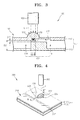
- FIG. 4 is a partially perspective view of a microfluidic system according to another embodiment of the present invention.
- FIG. 5 is a longitudinal cross-sectional view of the microfluidic system taken along a line V-V of FIG. 4 .
- FIG. 1 is a perspective view of a microfluidic system 100 according to an embodiment of the present invention.
- FIG. 2 is a partially enlarged perspective view of the microfluidic system 100 of FIG. 1 .
- FIG. 3 is a longitudinal cross-sectional view of the microfluidic system 100 taken along a line III-III' of FIG. 2 .
- the microfluidic system 100 includes a microfluidic device 110 including a rotatable disk-type substrate 111, a spindle motor 102 for supporting and rotating the microfluidic device 110, and an energy source 105.
- the energy source 105 is a laser light source 105 and is located with distance from the substrate 111.
- the microfluidic device 110 includes a chamber 115 for housing a fluid in the substrate 110, a channel 117 for moving a fluid, and a valve 120 for controlling flows of fluid moving along the channel 117.
- the chamber 115, the channel 117 and the valve 120 are arranged according to intended functions of biochemical field (e.g., centrifugal separation of a fluid sample, an immunoassay, gene analysis or the like). That is, the microfluidic device 110 is not limited to the arrangement shape of the chamber 115, the channel 117 and the valve 120 that are illustrated in FIG. 1 . That is, the microfluidic device 110 can be designed to have various arrangements and/or shapes of the structure according to the desired use of the microfluidic device.
- the spindle motor 102 rotates the microfluidic device 110 in order to apply a driving pressure based on a centrifugal force to a fluid remaining in the chamber 115 or channel 117 of the microfluidic device 110.
- the fluid remaining in the microfluidic device 110 is pushed towards a circumference of the substrate 111 due to the rotation of the spindle motor 102.
- the laser light source 105 is an example of an energy source for emitting magnetic waves to the valve 120, and projects a laser light L, which is a kind of electromagnetic wave, towards the valve 120 of the microfluidic device 110 to provide energy to the valve 120.
- the laser light source 105 may include a laser diode (LD).
- the valve 120 absorbs electromagnetic wave energy, which is provided in the form of the laser light L, and changes into a fluidic phase (e.g., melted).
- the valve 120 is referred to as a 'normally closed valve' which closes the channel 117 so that a fluid may not flow before the valve 120 changes into a fluidic phase by, for example, absorbing electromagnetic wave energy.
- the valve 120 includes a phase transition material that is melted by electromagnetic wave energy, and a plurality of minute heating particles that are diffused in the phase transition material and absorb electromagnetic wave energy to emit heat.
- the phase transition material may be wax.
- the wax When the wax is heated, the wax is melted to change into a liquid state and volume expansion of the wax occurs.
- the wax may be paraffin wax, microcrystalline wax, synthetic wax or natural wax.
- the phase transition material may be gel or thermoplastic resin.
- the gel may be polyacrylamide, polyacrylates, polymethacrylates or polyvinylamides.
- the thermoplastic resin may be cyclic olefin copolymer (COC), polymethylmethacrylate (PMMA), polycarbonate (PC), polystyrene (PS), polyoxymethylene (POM), perfluoralkoxy (PFA), polyvinylchloride (PVC), polypropylene (PP), polyethylene terephthalate (PET), polyetheretherketone (PEEK), polyamide (PA), polysulfone (PSU), PVDF(polyvinylidene fluoride) or the like.
- COC cyclic olefin copolymer
- PMMA polymethylmethacrylate
- PC polycarbonate
- PS polystyrene
- POM polyoxymethylene
- PFA perfluoralkoxy
- PVC polyvinylchloride
- PP polypropylene
- Minute heating particles have a diameter in the range of 1 nm to 100 ⁇ m so as to freely pass through the minute channel 117, which usually have a depth of about 0.1 mm and a width of about 1 mm.
- the minute heating particles which may be employed in the present invention, are characterized that the temperature of minute heating particles is remarkably increased to emit heat when electromagnetic wave energy is provided using laser light L irradiation and the minute heating particles are evenly diffused in the phase transition material.
- the minute heating particle may include a core including a metal component and a hydrophobic surface structure.
- the minute heating particle may include a core formed of Fe, and a shell surrounding Fe core, the shell includes a plurality of surfactant components combined with Fe.
- the minute heating particles are kept in a state in which the minute heating particles are diffused in carrier oil.
- the carrier oil may also be hydrophobic so that the minute heating particle including the hydrophobic surface structure may be evenly or homogenously dispersed in the carrier oil.
- the minute heating particles are not limited to polymer particles, of which exemplary list is described above. That is, the minute heating particles may be a form of quantum dots or magnetic beads.
- the minute heating particles may be minute metal oxide particles such as Al 2 O 3 , TiO 2 , Ta 2 O 3 , Fe 2 O 3 , Fe 3 O 4 , or HfO 2 .
- the valve 120 may not necessarily include the minute heating particles. That is, the valve 120 may be formed of only the phase transition material without the minute heating particles.
- the substrate 111 includes an upper plate 112 and a lower plate 113 that are bonded each other.
- the upper plate 112 and the lower plate 113 can be bonded using supersonic fusion, or by interposing double-sided adhesive tape therebetween.
- the upper plate 112 and the lower plate 113 may be fabricated using injection molding of thermoplastic resin.
- the microfluidic system 100 includes the laser light source 105 disposed above the microfluidic device 110, the laser light L passes through the upper plate 112 to be incident to the valve 120. Accordingly, at least the upper plate 112 may be transparent such that electromagnetic waves may easily pass through the upper plate 112.
- the microfluidic device 110 includes a means 122 for concentrating the energy applied to the valve 120. For example, a convex lens 122 which focuses (or concentrates) the laser light L projected from the laser light source 105 towards the valve 120 may be used to enhance melting of the valve 120 and prevent incomplete melting of the valve 120.
- the convex lens 122 is formed on a portion of the substrate 111, which covers the location of the valve 120.
- the convex lens 122 may be integrally formed on the upper plate 112 using injection molding of thermoplastic resin. One or both of the surfaces of the lens 122 may convex.
- the present invention is not limited to the microfluidic device 110 including the upper plate 112 having the convex lens 122 integrally formed thereon. That is, a microfluidic device according to the present invention may include a lens detachably attached onto a substrate.
- the present invention may include a microfluidic system in which an energy source is disposed below a microfluidic device, and accordingly a lens is disposed on a lower plate.
- the channel 117 comprises a first area 118 of a first dimension D1 in a portion and a pair of second areas 119 adjacent to the first area 118.
- the second areas 119 are of a second dimension D2 which is greater than D1.
- the microfluidic device 110 includes a valve forming material housing unit 125 that is formed on a portion that is connected to the channel 117 and is not in the channel 117.
- the valve forming material housing unit 125 is formed on a lower surface of the upper plate 112 in the form of a groove. A melted valve forming material M is injected into the valve forming material housing unit 125 to be hardened.
- valve forming material When the valve forming material is melted by energy, such as heat, applied to the valve, the melted valve forming material flows and remains in the first area 118 due to capillary force. The valve forming material remaining in the first area 118 hardens into a solid state at room temperature, thereby closing the channel 117.
- the laser light L is irradiated to the valve 120 closing the channel 117 using the laser light source 105 for a period of time, the minute heating particles included in the valve 120 rapidly emit heat to rapidly heat the phase transition material.
- the valve 120 is rapidly melted.
- the channel 117 becomes open, and flow of a fluid along the channel 117 can occur. Referring to FIG.
- the convex lens 122 condenses the laser light L projected from the laser light source 105 to the valve 120 in the microfluidic system 100, operational errors due to imperfect meting of a part of the valve 120, in which the channel 117 is not completely opened, are prevented. Since the laser light L is condensed to the valve 120, although the laser light source 105 having relatively low output is used, reliable operation of the valve 120 can be ensured. Since a lens and a barrel are not necessary to be equipped in the laser light source 105, and the convex lens 122 is integrally formed on the upper plate 112 using injection molding, the manufacturing costs of the microfluidic system 100 can be reduced.
- FIG. 4 is a partially perspective view of a microfluidic system 200 according to another embodiment of the present invention.
- FIG. 5 is a longitudinal cross-sectional view of the microfluidic system 200 taken along a line V-V' of FIG. 4 .
- the microfluidic system 200 includes a microfluidic device 210, and a laser light source 205 spaced from the microfluidic device 210.
- the microfluidic device 210 includes a substrate 211, a channel 217 formed in the substrate 211, and a valve 220 for controlling flow of a fluid flowing along the channel 217.
- the valve 220 does not close the channel 217 before the valve 220 absorbs electromagnetic wave energy. However, when the valve 220 absorbs electromagnetic wave energy, the valve 220 closes the channel 217. Thus, the valve 220 is referred to as a 'normally opened valve.'
- the valve 220 includes a phase transition material, and a plurality of minute heating particles that are diffused in the phase transition material and absorb electromagnetic wave energy to emit heat.
- the valve 220 and a valve forming material for forming the valve 220 are respectively the same as the valve 120 and the valve forming material of the microfluidic system 100 of FIGS. 2 and 3 , described above, and thus their descriptions will be omitted.
- the substrate 211 is formed by bonding an upper plate 212 and a lower plate 213.
- the upper plate 212 and the lower plate 213 can be bonded using supersonic fusion, or by interposing double-sided adhesive tape therebetween.
- the upper plate 212 and the lower plate 213 can be fabricated using injection molding of thermoplastic resin.
- a valve chamber 225 and a connection unit 226 are disposed in the substrate 211, wherein the valve chamber 225 is disposed around the channel 217 and the connection unit 226 connects the valve chamber 225 to the channel 217.
- the valve chamber 225 houses the valve 220.
- the channel 217, the valve chamber 225 and the connection unit 226 are formed on the lower plate 213.
- the present invention is not limited to the structure shown in the drawings. That is, at least one of a channel, a valve chamber and a connection unit may be formed on an upper plate.
- the valve 220 occupies a relatively large area of the substrate 211 unlike the valve 120 illustrated in FIGS. 2 and 3 . Accordingly, when a cross sectional area of the light emitted by the laser light source 205 is smaller than the occupying area of the valve 220 (for example, the case where the laser light source 205 includes a laser diode), the valve 220 may be partially melted to cause operation errors of the valve 220.
- the microfluidic device 210 includes a means for diverging energy beam applied to the valve 220.
- concave lens 222 radiating a laser light L projected from the laser light source 205 may be used in order to prevent the operational errors of the valve 220.
- the concave lens 222 is formed on a portion of the substrate 211, which overlaps the valve 220.
- the concave lens 222 is integrally formed on the upper plate 212 using injection molding of thermoplastic resin.
- the present invention is not limited to the microfluidic device 210 including the upper plate 212 having the concave lens 222 integrally thereon. That is, a microfluidic device according to the present invention may include a lens detachably attached onto a substrate.
- the present invention may include a microfluidic system in which an energy source is disposed below a microfluidic device, and accordingly a lens is disposed on a lower plate.
- the minute heating particles included in the valve 220 rapidly emit heat to rapidly heat the phase transition material.
- the valve 220 is rapidly melted and expanded.
- the valve 220 flows into the channel 217 through the connection unit 226.
- the valve 220 is hardened in the channel 217 to close the channel 217.
- the concave lens 222 diverges the laser light L projected from the laser light source 205 such that the laser light L may be incident on an entire area of the valve 220 in the microfluidic system 200, operational errors due to imperfect melting of a part of the valve 220, in which the channel 217 is not completely opened, are prevented.
- the number of laser diodes required for configuring the laser light source 205 can be reduced. Since a lens and a barrel are not necessary to be equipped in the laser light source 205, and the concave lens 222 is integrally formed on the upper plate 212 using injection molding, the manufacturing costs of the microfluidic system 200 can be reduced.
- the microfluidic device 210 may have a convex lens and a concave lens, wherein the convex lens is disposed between the energy source and the valve contained in the channel, and wherein the lens concentrates the beam of the energy and wherein the concave lens is disposed between the energy source and the valve contained in the chamber, and wherein the lens diverges the beam of the energy
- the microfluidic device 210 is fabricated using a method including preparing the lower plate 213 having the channel 217, the connection unit 226 and the valve chamber 225, and the upper plate 212 having the concave lens 222, forming the valve 220 by injecting the valve forming material into the valve chamber 225 of the lower plate 213 to be hardened, and bonding the upper plate 212 and the lower plate 213 so that a lower surface of the upper plate 212 and an upper surface of the lower plate 213 may face each other.
- supersonic fusion or double-sided adhesive tape can be used.
- a valve included in the microfluidic system closes or opens a channel by irradiating electromagnetic waves, and thus the valve having short response time can be embodied.
- a lens is provided on a substrate, and thus errors of controlling flow of a fluid, which are generated when a valve is partially melted, can be prevented.
- a lens and a barrel are not required for an energy source emitting electromagnetic waves. Accordingly, the manufacturing costs can be reduced.
Landscapes
- Chemical & Material Sciences (AREA)
- Engineering & Computer Science (AREA)
- General Engineering & Computer Science (AREA)
- Dispersion Chemistry (AREA)
- Health & Medical Sciences (AREA)
- Mechanical Engineering (AREA)
- Analytical Chemistry (AREA)
- General Health & Medical Sciences (AREA)
- Chemical Kinetics & Catalysis (AREA)
- Clinical Laboratory Science (AREA)
- Hematology (AREA)
- Toxicology (AREA)
- General Physics & Mathematics (AREA)
- Life Sciences & Earth Sciences (AREA)
- Biochemistry (AREA)
- Physics & Mathematics (AREA)
- Immunology (AREA)
- Pathology (AREA)
- Micromachines (AREA)
- Physical Or Chemical Processes And Apparatus (AREA)
- Temperature-Responsive Valves (AREA)
- Electrically Driven Valve-Operating Means (AREA)
Applications Claiming Priority (1)
| Application Number | Priority Date | Filing Date | Title |
|---|---|---|---|
| KR1020070043026A KR101258434B1 (ko) | 2007-05-03 | 2007-05-03 | 미세유동 시스템 및,이의 제조방법 |
Publications (3)
| Publication Number | Publication Date |
|---|---|
| EP2030686A2 true EP2030686A2 (de) | 2009-03-04 |
| EP2030686A3 EP2030686A3 (de) | 2009-09-23 |
| EP2030686B1 EP2030686B1 (de) | 2011-10-26 |
Family
ID=39939657
Family Applications (1)
| Application Number | Title | Priority Date | Filing Date |
|---|---|---|---|
| EP08155480A Active EP2030686B1 (de) | 2007-05-03 | 2008-04-30 | Mikrofluidische Vorrichtung und mikrofluidisches System damit |
Country Status (3)
| Country | Link |
|---|---|
| US (2) | US7981385B2 (de) |
| EP (1) | EP2030686B1 (de) |
| KR (1) | KR101258434B1 (de) |
Cited By (3)
| Publication number | Priority date | Publication date | Assignee | Title |
|---|---|---|---|---|
| EP2119505A1 (de) * | 2008-05-14 | 2009-11-18 | Samsung Electronics Co., Ltd. | Ventileinheit, mikrofluidische Vorrichtung damit und Verfahren zur Herstellung der Ventileinheit |
| GB2468111A (en) * | 2009-02-23 | 2010-08-25 | Univ Dublin City | Multilayer Fluidic Device |
| US11478792B2 (en) | 2016-10-03 | 2022-10-25 | Terumo Bct, Inc. | Centrifugal fluid separation device |
Families Citing this family (20)
| Publication number | Priority date | Publication date | Assignee | Title |
|---|---|---|---|---|
| US8715446B2 (en) * | 2004-10-13 | 2014-05-06 | Rheonix, Inc. | Latent solvent-based microfluidic apparatus, methods, and applications |
| KR101258434B1 (ko) * | 2007-05-03 | 2013-05-02 | 삼성전자주식회사 | 미세유동 시스템 및,이의 제조방법 |
| KR100898022B1 (ko) * | 2007-12-21 | 2009-05-19 | 한국전기연구원 | 랩온어칩 |
| KR101130698B1 (ko) * | 2009-11-03 | 2012-04-02 | 삼성전자주식회사 | 밸브 유닛과 이를 구비한 미세유동장치 및 밸브 유닛의 구동방법 |
| KR20110056168A (ko) * | 2009-11-20 | 2011-05-26 | 삼성전자주식회사 | 미세유동장치, 광조사장치 및 이를 포함하는 미세유동시스템과 그 구동방법 |
| KR101422573B1 (ko) * | 2009-11-26 | 2014-07-25 | 삼성전자 주식회사 | 원심력기반의 미세유동장치 및 이를 이용한 면역혈청검사방법 |
| KR101306338B1 (ko) * | 2011-11-09 | 2013-09-06 | 삼성전자주식회사 | 미세유동장치 및 이를 포함하는 미세유동시스템 |
| TWI456196B (zh) | 2012-04-24 | 2014-10-11 | Ind Tech Res Inst | 檢體免疫分析檢測裝置 |
| KR101439483B1 (ko) | 2012-12-05 | 2014-09-15 | 매쓰파워 주식회사 | 유공 폐쇄막을 이용한 박막 밸브 장치 |
| TWI499779B (zh) | 2013-07-04 | 2015-09-11 | Ind Tech Res Inst | 檢測晶片及其使用方法 |
| KR102176587B1 (ko) | 2013-10-15 | 2020-11-10 | 삼성전자주식회사 | 시료분석장치, 시료분석방법, 및 밸브의 동적 작동 방법 |
| USD841186S1 (en) * | 2015-12-23 | 2019-02-19 | Tunghai University | Biochip |
| AU2017368267B2 (en) * | 2016-12-01 | 2022-12-15 | Berkeley Lights, Inc. | Apparatuses, systems and methods for imaging micro-objects |
| WO2019187294A1 (ja) * | 2018-03-30 | 2019-10-03 | 富士フイルム株式会社 | チップ、混合装置及び混合方法 |
| CN108591610B (zh) * | 2018-04-27 | 2024-04-23 | 湖南乐准智芯生物科技有限公司 | 一种微流控系统及微阀、控制方法 |
| CN108679301B (zh) * | 2018-09-06 | 2019-01-08 | 湖南乐准智芯生物科技有限公司 | 一种微阀与液体之间的隔离系统、控制方法及生物芯片 |
| CN111558402B (zh) * | 2020-03-10 | 2021-05-11 | 青岛英赛特生物科技有限公司 | 一种气压驱动的离心式微流控检测芯片 |
| CN111205966B (zh) * | 2020-04-18 | 2020-07-21 | 博奥生物集团有限公司 | 样本提取芯片和生物反应装置 |
| KR102559413B1 (ko) * | 2020-10-19 | 2023-07-26 | 한국과학기술원 | 미세유체칩용 왁스 밸브, 이를 포함하는 미세유체칩 및 미세유체칩을 이용한 시료 분석 방법 |
| CN115532330A (zh) * | 2022-10-10 | 2022-12-30 | 深圳大学 | 一种微流控芯片三维管道制作方法 |
Citations (1)
| Publication number | Priority date | Publication date | Assignee | Title |
|---|---|---|---|---|
| WO1999044217A1 (en) | 1998-02-24 | 1999-09-02 | Caliper Technologies Corporation | Microfluidic devices and systems incorporating integrated optical elements |
Family Cites Families (12)
| Publication number | Priority date | Publication date | Assignee | Title |
|---|---|---|---|---|
| JP3469585B2 (ja) * | 1997-05-23 | 2003-11-25 | ガメラ バイオサイエンス コーポレイション | ミクロ流体工学システムでの流動運動を駆動するために向心的加速を使用するための装置および方法 |
| US6375901B1 (en) | 1998-06-29 | 2002-04-23 | Agilent Technologies, Inc. | Chemico-mechanical microvalve and devices comprising the same |
| US6778724B2 (en) * | 2000-11-28 | 2004-08-17 | The Regents Of The University Of California | Optical switching and sorting of biological samples and microparticles transported in a micro-fluidic device, including integrated bio-chip devices |
| WO2002046721A2 (en) * | 2000-12-08 | 2002-06-13 | Burstein Technologies, Inc. | Optical discs for measuring analytes |
| JP3548858B2 (ja) | 2001-01-22 | 2004-07-28 | 独立行政法人産業技術総合研究所 | 流量の制御方法及びそれに用いるマイクロバルブ |
| EP1434685A1 (de) * | 2001-10-08 | 2004-07-07 | California Institute Of Technology | Mikrohergestellte linsen, verfahren zur deren herstellung, und anwendungen dafür |
| US20030156991A1 (en) * | 2001-10-23 | 2003-08-21 | William Marsh Rice University | Optomechanically-responsive materials for use as light-activated actuators and valves |
| US6679279B1 (en) * | 2002-07-10 | 2004-01-20 | Motorola, Inc. | Fluidic valve having a bi-phase valve element |
| CN101158695A (zh) * | 2002-12-04 | 2008-04-09 | 斯宾克斯公司 | 流体的可程控微量控制用方法 |
| US20070092409A1 (en) | 2005-10-21 | 2007-04-26 | Beatty Christopher C | Reconfigurable valve using optically active material |
| KR100851980B1 (ko) * | 2006-09-05 | 2008-08-12 | 삼성전자주식회사 | 열 활성 유닛을 구비한 원심력 기반의 미세유동 장치, 이를포함하는 미세유동 시스템 및 상기 미세유동 시스템의구동방법 |
| KR101258434B1 (ko) * | 2007-05-03 | 2013-05-02 | 삼성전자주식회사 | 미세유동 시스템 및,이의 제조방법 |
-
2007
- 2007-05-03 KR KR1020070043026A patent/KR101258434B1/ko active Active
-
2008
- 2008-04-30 EP EP08155480A patent/EP2030686B1/de active Active
- 2008-05-02 US US12/114,214 patent/US7981385B2/en active Active
-
2011
- 2011-06-10 US US13/157,816 patent/US8221704B2/en active Active
Patent Citations (1)
| Publication number | Priority date | Publication date | Assignee | Title |
|---|---|---|---|---|
| WO1999044217A1 (en) | 1998-02-24 | 1999-09-02 | Caliper Technologies Corporation | Microfluidic devices and systems incorporating integrated optical elements |
Non-Patent Citations (1)
| Title |
|---|
| J.-M. PARK ET AL.: "Multifunctional microvalves control by optical illumination on nanoheaters and its application in centrifugal microfluidic devices", LAB ON A CHIP, ROYAL SOCIETY OF CHEMISTRY, vol. 7, 2007, XP007902269, DOI: doi:10.1039/b616112j |
Cited By (5)
| Publication number | Priority date | Publication date | Assignee | Title |
|---|---|---|---|---|
| EP2119505A1 (de) * | 2008-05-14 | 2009-11-18 | Samsung Electronics Co., Ltd. | Ventileinheit, mikrofluidische Vorrichtung damit und Verfahren zur Herstellung der Ventileinheit |
| US8429821B2 (en) | 2008-05-14 | 2013-04-30 | Samsung Electronics Co., Ltd. | Method of fabricating valve unit in a microfluidic device |
| GB2468111A (en) * | 2009-02-23 | 2010-08-25 | Univ Dublin City | Multilayer Fluidic Device |
| US11478792B2 (en) | 2016-10-03 | 2022-10-25 | Terumo Bct, Inc. | Centrifugal fluid separation device |
| US12285757B2 (en) | 2016-10-03 | 2025-04-29 | Terumo Bct, Inc. | Centrifugal fluid separation device |
Also Published As
| Publication number | Publication date |
|---|---|
| KR20080097763A (ko) | 2008-11-06 |
| US20080274015A1 (en) | 2008-11-06 |
| KR101258434B1 (ko) | 2013-05-02 |
| EP2030686B1 (de) | 2011-10-26 |
| US8221704B2 (en) | 2012-07-17 |
| US7981385B2 (en) | 2011-07-19 |
| US20110262321A1 (en) | 2011-10-27 |
| EP2030686A3 (de) | 2009-09-23 |
Similar Documents
| Publication | Publication Date | Title |
|---|---|---|
| US7981385B2 (en) | Microfluidic device and microfluidic system with the same | |
| US7951332B2 (en) | Centrifugal force based microfluidic device for dilution and microfluidic system including the same | |
| EP1980322B1 (de) | Mikrofluidische Vorrichtung auf Zentrifugalkraftbasis und mikrofluidisches System | |
| EP1920843B1 (de) | Ventileinheit, Mikrofluidvorrichtung mit der Ventileinheit und mikrofluidisches Substrat | |
| US8235073B2 (en) | Microfluidic valve unit for controlling flow of fluid and method of fabricating the same | |
| EP2324924B1 (de) | Mikrofluidisches system | |
| KR101130698B1 (ko) | 밸브 유닛과 이를 구비한 미세유동장치 및 밸브 유닛의 구동방법 | |
| US8048387B2 (en) | Centrifugal microfluidic device having sample distribution structure and centrifugal microfluidic system including the centrifugal microfluidic device | |
| US8119079B2 (en) | Microfluidic apparatus having fluid container | |
| EP1994987A2 (de) | Mikrofluidische Vorrichtung mit einem mikrofluidischen Chip sowie mikrofluidische Vorrichtung mit einem biomolekularen Mikroarray-Chip | |
| EP2006588A2 (de) | Mikrofluidisches Ventil, Herstellungsverfahren dafür und mikrofluidische Vorrichtung mit dem mikrofluidischen Ventil | |
| US8105551B2 (en) | Microfluidic device and method of fabricating the same | |
| KR101391736B1 (ko) | 미세유동 밸브, 상기 미세유동 밸브의 제조 방법 및 상기미세유동 밸브를 포함하는 미세유동 장치 | |
| KR101473871B1 (ko) | 미세유체 제어용 밸브 유닛의 제조방법, 미세유체 제어용밸브 유닛 및, 상기 밸브 유닛을 구비한 미세유동 장치 | |
| EP2119505B1 (de) | Verfahren zur Herstellung einer Ventileinheit |
Legal Events
| Date | Code | Title | Description |
|---|---|---|---|
| PUAI | Public reference made under article 153(3) epc to a published international application that has entered the european phase |
Free format text: ORIGINAL CODE: 0009012 |
|
| AK | Designated contracting states |
Kind code of ref document: A2 Designated state(s): AT BE BG CH CY CZ DE DK EE ES FI FR GB GR HR HU IE IS IT LI LT LU LV MC MT NL NO PL PT RO SE SI SK TR |
|
| AX | Request for extension of the european patent |
Extension state: AL BA MK RS |
|
| PUAL | Search report despatched |
Free format text: ORIGINAL CODE: 0009013 |
|
| AK | Designated contracting states |
Kind code of ref document: A3 Designated state(s): AT BE BG CH CY CZ DE DK EE ES FI FR GB GR HR HU IE IS IT LI LT LU LV MC MT NL NO PL PT RO SE SI SK TR |
|
| AX | Request for extension of the european patent |
Extension state: AL BA MK RS |
|
| 17P | Request for examination filed |
Effective date: 20100309 |
|
| 17Q | First examination report despatched |
Effective date: 20100414 |
|
| AKX | Designation fees paid |
Designated state(s): DE FR GB SE |
|
| GRAP | Despatch of communication of intention to grant a patent |
Free format text: ORIGINAL CODE: EPIDOSNIGR1 |
|
| RIN1 | Information on inventor provided before grant (corrected) |
Inventor name: YOO, JUNG-SUK Inventor name: LEE, JEONG-GUN Inventor name: PARK, JONG-MYEON |
|
| GRAS | Grant fee paid |
Free format text: ORIGINAL CODE: EPIDOSNIGR3 |
|
| GRAA | (expected) grant |
Free format text: ORIGINAL CODE: 0009210 |
|
| AK | Designated contracting states |
Kind code of ref document: B1 Designated state(s): DE FR GB SE |
|
| REG | Reference to a national code |
Ref country code: GB Ref legal event code: FG4D |
|
| REG | Reference to a national code |
Ref country code: DE Ref legal event code: R096 Ref document number: 602008010759 Country of ref document: DE Effective date: 20111222 |
|
| PG25 | Lapsed in a contracting state [announced via postgrant information from national office to epo] |
Ref country code: SE Free format text: LAPSE BECAUSE OF FAILURE TO SUBMIT A TRANSLATION OF THE DESCRIPTION OR TO PAY THE FEE WITHIN THE PRESCRIBED TIME-LIMIT Effective date: 20111026 |
|
| PLBE | No opposition filed within time limit |
Free format text: ORIGINAL CODE: 0009261 |
|
| STAA | Information on the status of an ep patent application or granted ep patent |
Free format text: STATUS: NO OPPOSITION FILED WITHIN TIME LIMIT |
|
| RAP2 | Party data changed (patent owner data changed or rights of a patent transferred) |
Owner name: SAMSUNG ELECTRONICS CO., LTD. |
|
| 26N | No opposition filed |
Effective date: 20120727 |
|
| REG | Reference to a national code |
Ref country code: DE Ref legal event code: R097 Ref document number: 602008010759 Country of ref document: DE Effective date: 20120727 |
|
| REG | Reference to a national code |
Ref country code: FR Ref legal event code: PLFP Year of fee payment: 9 |
|
| REG | Reference to a national code |
Ref country code: FR Ref legal event code: PLFP Year of fee payment: 10 |
|
| REG | Reference to a national code |
Ref country code: FR Ref legal event code: PLFP Year of fee payment: 11 |
|
| REG | Reference to a national code |
Ref country code: DE Ref legal event code: R081 Ref document number: 602008010759 Country of ref document: DE Owner name: PRECISION BIOSENSOR INC., DAEJEON, KR Free format text: FORMER OWNER: SAMSUNG ELECTRONICS CO., LTD., SUWON-SI, GYEONGGI-DO, KR |
|
| REG | Reference to a national code |
Ref country code: GB Ref legal event code: 732E Free format text: REGISTERED BETWEEN 20220825 AND 20220831 |
|
| REG | Reference to a national code |
Ref country code: FR Ref legal event code: PLFP Year of fee payment: 16 |
|
| PGFP | Annual fee paid to national office [announced via postgrant information from national office to epo] |
Ref country code: FR Payment date: 20250321 Year of fee payment: 18 |
|
| PGFP | Annual fee paid to national office [announced via postgrant information from national office to epo] |
Ref country code: GB Payment date: 20250320 Year of fee payment: 18 |
|
| PGFP | Annual fee paid to national office [announced via postgrant information from national office to epo] |
Ref country code: DE Payment date: 20250325 Year of fee payment: 18 |