EP2028919A1 - A display apparatus having a grounding bracket - Google Patents
A display apparatus having a grounding bracket Download PDFInfo
- Publication number
- EP2028919A1 EP2028919A1 EP08162694A EP08162694A EP2028919A1 EP 2028919 A1 EP2028919 A1 EP 2028919A1 EP 08162694 A EP08162694 A EP 08162694A EP 08162694 A EP08162694 A EP 08162694A EP 2028919 A1 EP2028919 A1 EP 2028919A1
- Authority
- EP
- European Patent Office
- Prior art keywords
- wing portions
- wing
- wing portion
- chassis
- display panel
- Prior art date
- Legal status (The legal status is an assumption and is not a legal conclusion. Google has not performed a legal analysis and makes no representation as to the accuracy of the status listed.)
- Withdrawn
Links
Images




Classifications
-
- H—ELECTRICITY
- H05—ELECTRIC TECHNIQUES NOT OTHERWISE PROVIDED FOR
- H05K—PRINTED CIRCUITS; CASINGS OR CONSTRUCTIONAL DETAILS OF ELECTRIC APPARATUS; MANUFACTURE OF ASSEMBLAGES OF ELECTRICAL COMPONENTS
- H05K9/00—Screening of apparatus or components against electric or magnetic fields
- H05K9/0064—Earth or grounding circuit
-
- H—ELECTRICITY
- H01—ELECTRIC ELEMENTS
- H01J—ELECTRIC DISCHARGE TUBES OR DISCHARGE LAMPS
- H01J11/00—Gas-filled discharge tubes with alternating current induction of the discharge, e.g. alternating current plasma display panels [AC-PDP]; Gas-filled discharge tubes without any main electrode inside the vessel; Gas-filled discharge tubes with at least one main electrode outside the vessel
- H01J11/20—Constructional details
- H01J11/34—Vessels, containers or parts thereof, e.g. substrates
- H01J11/44—Optical arrangements or shielding arrangements, e.g. filters, black matrices, light reflecting means or electromagnetic shielding means
-
- H—ELECTRICITY
- H01—ELECTRIC ELEMENTS
- H01J—ELECTRIC DISCHARGE TUBES OR DISCHARGE LAMPS
- H01J11/00—Gas-filled discharge tubes with alternating current induction of the discharge, e.g. alternating current plasma display panels [AC-PDP]; Gas-filled discharge tubes without any main electrode inside the vessel; Gas-filled discharge tubes with at least one main electrode outside the vessel
- H01J11/10—AC-PDPs with at least one main electrode being out of contact with the plasma
-
- H—ELECTRICITY
- H05—ELECTRIC TECHNIQUES NOT OTHERWISE PROVIDED FOR
- H05K—PRINTED CIRCUITS; CASINGS OR CONSTRUCTIONAL DETAILS OF ELECTRIC APPARATUS; MANUFACTURE OF ASSEMBLAGES OF ELECTRICAL COMPONENTS
- H05K9/00—Screening of apparatus or components against electric or magnetic fields
- H05K9/0073—Shielding materials
- H05K9/0094—Shielding materials being light-transmitting, e.g. transparent, translucent
- H05K9/0096—Shielding materials being light-transmitting, e.g. transparent, translucent for television displays, e.g. plasma display panel
-
- H—ELECTRICITY
- H01—ELECTRIC ELEMENTS
- H01J—ELECTRIC DISCHARGE TUBES OR DISCHARGE LAMPS
- H01J2211/00—Plasma display panels with alternate current induction of the discharge, e.g. AC-PDPs
- H01J2211/20—Constructional details
- H01J2211/34—Vessels, containers or parts thereof, e.g. substrates
- H01J2211/44—Optical arrangements or shielding arrangements, e.g. filters or lenses
- H01J2211/446—Electromagnetic shielding means; Antistatic means
Definitions
- the present invention relates to a display apparatus, and more particularly, to a display apparatus which can improve electromagnetic shielding by enhancing grounding performance of a chassis and a filter, which are directly attached in front of the display panel.
- a conventional plasma display apparatus is a flat display apparatus which includes discharge electrodes on each of the facing surfaces of a front substrate and a rear substrate. Discharge gas is filled in a discharge space sealed between the front and rear substrates, and then predetermined power is applied to each discharge electrode so as to generate ultraviolet rays in the discharge space. Accordingly, the conventional plasma display apparatus creates an image by using light emitted by exciting a phosphor substance of a phosphor layer by using the ultraviolet rays.
- Such a plasma display apparatus is manufactured by combining a front panel and a rear panel after manufacturing the front and rear panels separately, combining a chassis base to the back of the panel assembly, attaching a driving circuit board, which can transmit an electric signal to the panel assembly, to the back of the chassis base, directly attaching a filter to a display panel or attaching a filter to the panel by using a filter holder, and then installing the result of the manufacturing process described above in a case.
- the filter is installed in order to intercept an electromagnetic wave generated from the display panel, infrared rays, neon radiation, or external light reflection.
- it is important to tightly ground the filter and the chassis base in order to be shielded from an electromagnetic wave and intercept infrared rays, neon radiation, or external light reflection.
- the present invention provides a display apparatus, which enables a ground bracket, which grounds a chassis and a directly attached filter that is attached to the front surface of a display panel, to be stably electrically connected to each of the directly attached filter and the chassis.
- a grounding bracket for a display apparatus having a display panel to display an image, a filter having an electromagnetic shielding layer attached to a first surface of the display panel, and a chassis disposed on a second surface of the display panel, said ground bracket comprising first and second facing wing portions configured to receive an edge of a display panel therebetween so that the first wing portion makes electrical contact with the electromagnetic shielding layer of the filter and the second wing portion makes electrical contact with the chassis, the bracket including means to press the first and second wing portions in a direction towards each other to improve the contact of the first and second wing portions with the electromagnetic shielding layer and the chassis, respectively.
- the means for pressing the first and second wing portions towards each other comprises a pressing device.
- the pressing device may be a screw, the first and second wing portions having aligned holes therein to receive the screw so as to squeeze the first and second wing portions in a direction towards each other.
- the screw has a head and the hole in the second wing portion is threaded, the screw being inserted through the aligned holes in the first wing portion and threadingly engaged with the threaded hole in the second wing portion with the head engaging the first wing portion.
- the pressing device is a rivet and the first and second wing portions having aligned holes therein to receive the rivet so as to squeeze the first and second wing portions in a direction towards each other.
- the pressing device is a bolt and nut, the first and second wing portions having aligned holes therein to receive the bolt, the nut being threadable to the end of the bolt to squeeze the first and second wing portions in a direction towards each other as the nut is tightened.
- the nut has a head and is inserted through the aligned holes in the first and second wing portions with the head against the first wing portion, the nut threadingly coupling the bolt and engaging against the second wing portion.
- a conductive pad is placed between the first wing portion and the filter.
- the means for pressing the first and second wing portions together comprises forming the first and second wing portions from a resiliently flexible material configured such that the distance between the first and second wing portions is less than the distance between the first and second wing portions when the first and second wing portions have been elastically deformed to receive a display apparatus therebetween, so as to bias the first and second wing portions against the filter and the chassis, respectively.
- a display apparatus having a grounding bracket comprising a display panel which displays an image; a filter which includes an electromagnetic shielding layer and is directly attached to a first surface in which the image of the display panel is formed; a chassis, which is disposed on the side of a second surface, which is an opposite surface of the first surface, of the display panel and supports the display panel; the first wing portion of the grounding bracket being electrically connected to the electromagnetic shielding layer of the filter and the second wing portion being electrically connected to the chassis, the first and second wing portions being pressed towards each other by said means.
- the pressing means By using the pressing means, the first and second wing portions of the ground bracket are tightened toward each other, the first wing portion of the ground bracket is adhered closely to the chassis, and the second wing portion of the ground bracket is adhered closely to the filter, and thus a grounding performance between the electromagnetic shielding layer and the chassis improves. As a result, an electromagnetic shielding performance of the filter increases, and accordingly, the quality of the display apparatus improves.
- a display apparatus including a display panel, which displays an image; a filter, which includes an electromagnetic shielding layer and is directly attached to a first surface in which the image of the display panel is formed; a chassis, which is disposed on the side of a second surface, which is an opposite surface of the first surface, of the display panel and supports the display panel; and a ground bracket, which includes a conductive material, in which a first wing portion is electrically connected to the electromagnetic shielding layer of the filter, a second wing portion is electrically connected to the chassis, and the first and second wing portions substantially face each other under an elastic force.
- the first and second wing portions of the ground bracket are respectively closely adhered to the electromagnetic shielding layer of the filter and the chassis by using the ground bracket which has an elastic force. Accordingly, the first wing portion can be stably electrically connected to the chassis in a larger area, and the second wing portion can be stably electrically connected to the electromagnetic shielding layer of the filter in a larger area.
- An electromagnetic shielding performance of the filter is improved since the electromagnetic shielding layer is stably grounded to the chassis.
- FIG. 1 is an exploded perspective view illustrating a display apparatus 1 according to an embodiment of the present invention
- FIG. 2 is an enlarged cross-sectional view illustrating an area A illustrated in FIG. 1 according to an embodiment of the present invention.
- the display apparatus 1 includes a display panel 20, which displays an image, a chassis 30, which supports the display panel 20, and a front case 11 and a rear case 12, which accommodate and protect the display panel 20.
- the display panel 20 includes a front panel 21 and a rear panel 22.
- the front panel 21 includes a front substrate, X and Y electrodes formed in a predetermined pattern on the front substrate, a front dielectric layer in which the X and Y electrodes are embedded, and a protective layer coated on the surface of the front dielectric layer.
- the rear panel 22 includes a rear substrate, an address electrode formed crossing the X and Y electrodes, a rear dielectric layer in which the address electrode is embedded, barrier ribs disposed between the front and rear substrates and restricting discharge spaces, and phosphor layers applied in the inner sides of the barrier ribs.
- the chassis 30 is attached to the rear of the display panel 20.
- the heat dissipation member 24 quickly and smoothly eliminates heat generated in the display panel 20.
- the display panel 20 and the chassis 30 are attached using double sided tape 23.
- a driving circuit board (not shown) and other circuit boards are disposed on the rear surface of the chassis 30.
- the driving circuit board provides an electric signal that drives the display panel 20. Accordingly, the driving circuit board and the display panel 20 are electrically connected using signal transmission means (not shown), such as a tape carrier package (TCP) or tape automated bonding (TAB).
- signal transmission means such as a tape carrier package (TCP) or tape automated bonding (TAB).
- the chassis 30 supports such circuit boards and the display panel 20. Accordingly, the chassis 30 is formed of a material having rigidity so as to sufficiently support the circuit boards and the display panel 20. Also, the chassis 30 acts as an electrical ground to circuits in the circuit boards. Accordingly, the chassis 30 includes a conductive material. Moreover, the chassis 30 smoothly eliminates heat generated in the circuit boards and the display panel 20. Accordingly, the chassis 30 may include a material having high heat conductance. In other words, the chassis 30 is generally formed of aluminum, but the material forming the chassis 30 is not limited thereto. For example, the chassis 30 may be formed of plastic including a conductive material in some portion.
- a filter 15 is directly attached to the front surface of the display panel 20.
- the filter 15 is also called a directly attached filter, since the filter 15 is directly attached to the front surface of the display panel 20 that projects an image.
- the directly attached filter 15 is installed in order to intercept an electromagnetic wave generated from the display panel 20, infrared rays, neon radiation, and external light reflection.
- the directly attached filter 15 includes an electromagnetic shielding layer (not shown), wherein minute metal lines are disposed in a thin reticulatedmanner.
- the directly attached filter 15 may include an infrared rays interception layer, a neon radiation interception layer, and an external light reflection interception layer.
- the electromagnetic shielding layer should be grounded. Accordingly, a ground bracket 145 is provided.
- the ground bracket 145 includes a first wing portion 145a and a second wing portion 145b that face each other, and the ground bracket 145 has a " ⁇ "-shaped section.
- the shape of the ground bracket 145 is not limited thereto, as long as the first and second wing portions 145a and 145b face each other, and thus the ground bracket 145 may have a " ⁇ "-shaped section.
- the surface of the first wing portion 145a is electrically connected to the rear surface of the chassis 30, and the surface of the second wing portion 145b is electrically connected to the electromagnetic shielding layer included in the directly attached filter 15.
- the surface of the second wing portion 145b is electrically connected to a peripheral portion 15a.
- the rear surface of the chassis 30, which contacts the surface of the first wing portion 145a is formed of a material having high electric conductivity.
- the ground bracket may be formed of a material having high conductivity, such as aluminum or steel, or may include a material having high conductivity. Accordingly, the electromagnetic shielding layer can intercept the generation of the electromagnetic wave by being grounded to the chassis 30.
- the ground between the chassis 30 and the electromagnetic shielding layer may be unstable.
- the ground is unstable, an electromagnetic shielding performance remarkably decreases, and the ground between the chassis 30 and the directly attached filter 15 should be stable.
- the embodiments of the present invention include a pressing means, pressing mechanism or pressing device.
- the pressing means, pressing mechanism or pressing device may be a screw 140.
- the screw 140 is formed of a main body 140b, a head 140a, and a thread.
- the head 140a is connected to one end of the main body 140b, and the head 140a and the main body 140b are in one body.
- the diameter of the head 140a is larger than the diameter of the main body 140b.
- the thread is formed in a partial area of the main body 140b. In more detail, the thread is formed in an end portion of the main body 140b far from the head 140a.
- the main body 140b is inserted into the second wing portion 145b by penetrating the first wing portion 145a until the head 140a touches the first wing portion 145a.
- a thread (not shown), corresponding to the thread of the main body 140b, is formed in the second wing portion 145b. Accordingly, the main body 140b of the screw 140 is combined with the second wing portion 145b of the ground bracket 145.
- the head 140a presses the first wing portion 145a against the second wing portion 145b, and thus the first and second wing portions 145a and 145b are tightened in the facing direction. Accordingly, the first wing portion 145a is closely adhered to the chassis 30 and the second wing portion 145b is closely adhered to the directly attached filter 15, and thus a grounding performance between the electromagnetic shielding layer of the directly attached filter 15 and the chassis 30 improves. As a result, an electromagnetic shielding performance of the directly attached filter 15 improves, and accordingly, the quality of the display apparatus 1 improves.
- a washer may be disposed between the head 140a and the first wing portion 145a.
- the washer provides pre-tension between the head 140a and the first wing portion 145a in order to make sure that the screw 140 and the ground bracket 145 are tightened.
- FIG. 3 is a cross-sectional view illustrating an alternative example of the embodiment illustrated in FIG. 2.
- FIG. 3 is different from FIG. 2 , in that the proceeding direction of the screw 140 is opposite to that of the screw 140 of FIG. 2 .
- the screw 140 is tightened to the ground bracket 145 while proceeding from the second wing portion 145b to the first wing portion 145a.
- the remaining description of FIG.3 is the same as that of FIG. 2 .
- FIG. 4 is an enlarged cross-sectional view illustrating an area A illustrated in FIG. 1 according to another embodiment of the present invention.
- the pressing means, pressing mechanism or pressing device 240 is a bolt 241 and a nut 242.
- the bolt 241 is formed of a main body 241b, a head 241 a, and a thread.
- the head 241a is connected to one end of the main body 241b as one body and the diameter of the head 241a is smaller than the diameter of the main body 241b.
- a thread is formed in a partial portion of the main body 241b. In more detail, the thread is formed in one end of the main body 241b far from the head 241a.
- the main body 241b is inserted into a second wing portion 145b of a ground bracket 145 after penetrating a first wing portion 145a of the ground bracket 145 until the head 241a touches the first wing portion 145a. Then, the nut 242 is tightened to the thread of the main body 241b. By rotating the bolt 241 or the nut 242 in the tightening direction of the nut 242, the head 241a presses the first wing portion 145a against the second wing portion 145b, and thus the first and second wing portions 145a and 145b are tightened in the facing direction.
- the first wing portion 145a adheres closely to a chassis 30 and the second wing portion 145b adheres closely to a directly attached filter 15, and thus a grounding performance between an electromagnetic shielding layer of the directly attached filter 15 and the chassis 30 improves. Consequently, an electromagnetic shielding performance of the directly attached filter 15 improves, and thus the quality of the display apparatus 1 increases.
- the display apparatus 1 may further include a washer between the head 241a and the first wing portion 145a.
- the washer provides pre-tension between the head 241a and the first wing portion 145a in order to make sure that the bolt 241 and the ground bracket 145 are tightened.
- FIG. 5 is a cross-sectional view illustrating an alternative example of the embodiment illustrated in FIG. 4.
- FIG. 5 is different from FIG. 4 , in that the proceeding direction of the bolt 241 is opposite to that of the bolt 241 of FIG. 4 .
- the bolt 241 is tightened to the nut 242 while proceeding from the second wing portion 145b to the first wing portion 145a.
- the remaining description of FIG. 5 is the same as the description of FIG. 4 .
- FIG. 6 is an enlarged cross-sectional view illustrating an area A illustrated in FIG. 1 according to another embodiment of the present invention.
- the pressing means, pressing mechanism or pressing device is a rivet 340.
- the rivet 340 before being tightened to a ground bracket 345, may include a main body 340b, which penetrates a first wing portion 345a and a second wing portion 345b of the ground bracket 345, and a head 340a, which touches the second wing portion 345b and presses the second wing portion 345b against the first wing portion 345a.
- the head 340a is connected to one end of the main body 340b as one body, and the diameter of the head 340a is larger than the diameter of the main body 340b.
- the main body 340b is inserted into the second wing portion 345b after penetrating the second wing portion 345b until the head 340a touches the second wing portion 345b, and then the rivet 340 is tightened against the ground bracket 345 by enlarging the diameter of an end portion 340c of the main body 340b far from the head 340a.
- the first wing portion 345a and the second wing portion 345b are tightened in the facing direction. Accordingly, the first wing portion 345a is adhered closely to a chassis 30, and the second wing portion 345b is adhered closely to a directly attached filter 15, and thus a grounding performance between an electromagnetic shielding layer of the directly attached filter 15 and the chassis 30 improves. Consequently, an electromagnetic shielding performance of the directly attached filter 15 improves, and thus the quality of the display apparatus 1 improves.
- FIG. 6 illustrates the embodiment that the head 340a is disposed on the second wing portion 345b, but the location of the head 340a is not limited thereto, and the head 340a can be tightened against the ground bracket 345 while being disposed on the first wing portion 345a.
- FIG. 7 is a cross-sectional view illustrating another alternative example of the embodiment illustrated in FIG. 2 .
- a conductive pad 17 is disposed between the peripheral portion 15a of the electromagnetic shielding layer of the directly attached filter 15 and the second wing portion 145b of the ground bracket 145.
- the conductive pad 17 is a conductive member, which has both sides and are flat.
- the ground brackets 145, 245, and 345 are each disposed on the top and bottom of the display panel 20, but the locations of the ground brackets 145, 245, and 345 are not limited thereto.
- the ground brackets 145, 245, and 345 may be disposed on the left end and/or right end of the display panel 20.
- the ground brackets 145, 245, and 345 on one side extend in one direction, and thus the number of each of the ground brackets 145, 245, and 345 is one, but the number is not limited thereto. That is, the number of each of the ground brackets 145, 245, and 345 on one side may be 2, 3, 4, or more.
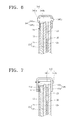
- FIG. 8 is an enlarged cross-sectional view illustrating a part of a display apparatus according to another embodiment of the present invention.
- the display apparatus 1 does not separately include the pressing means, pressing mechanism or pressing device, such as the screw.
- an elastic force is provided so that each end portion of a first wing portion 445a and a second wing portion 445b of a ground bracket 445 face each other.
- a sectional form of the ground bracket 445 is ' ⁇ ' or ' ⁇ ', and an elastic force is provided to the ground bracket 445 so that the distance between an end portion of the first wing portion 445a and an end portion of the second wing portion 445a when in position on the display apparatus is greater than the distance between the end portion of the first wing portion 445a and the end portion of the second wing portion 445b at a free state.
- the space between the first and second wing portions 445a and 445b are widened, and then the display panel 20 is disposed between the first wing portion 445a and the second wing portion 445b.
- the first and second wing portions 445a and 445b are released to their original state, the first wing portion 445a adheres closely to the chassis 30 and the second wing portion 445b adheres closely to the directly attached filter 15 according to the elastic force between the first and second wing portions 445a and 445b. Accordingly, a grounding performance between an electromagnetic shielding layer of the directly attached filter 15 and the chassis 30 improves. Consequently, an electromagnetic shielding performance of the directly attached filter 15 improves, and thus the quality of the display apparatus 1 improves.
- FIG. 9A is a graph illustrating the amount of electromagnetic radiation in a conventional plasma display apparatus including the directly attached filter 15 and FIG. 9B is a graph illustrating the amount of electromagnetic radiation in a plasma display apparatus according to an embodiment of the present invention.
- An experiment for measuring the amount of electromagnetic radiation is performed in a chamber, in which the distance between the display panel 20 and a measurement antenna is 3 m.
- a permissible standard of the amount of electromagnetic radiation is based on Class B (for home use) according to the Federal Communications Commission (FCC) standard of the USA.
- FCC Federal Communications Commission
- the amount of electromagnetic radiation should be below or equal to 40 dB ⁇ V in a section between 30 MHz to 230 MHz, and the amount of electromagnetic radiation should be below or equal to 47 dB ⁇ V in a section between 230 MHz to 1 GHz.
- thick solid lines L1 and L2 denote a standard value of the amount of electromagnetic radiation.
- FIG. 9A three peak values of the amount of electromagnetic radiation exceeds 40 dB ⁇ V (L1), which is the standard value in the section ranging between 30 MHz to 230 MHz, and thus the conventional plasma display apparatus is determined to be inferior for home use in a quality test.
- the amount of electromagnetic radiation does not exceed 40dB ⁇ V (L1) in any section, and thus the plasma display apparatus according to the current embodiment has superior electromagnetic shielding.
Landscapes
- Engineering & Computer Science (AREA)
- Physics & Mathematics (AREA)
- Plasma & Fusion (AREA)
- Microelectronics & Electronic Packaging (AREA)
- Electromagnetism (AREA)
- Devices For Indicating Variable Information By Combining Individual Elements (AREA)
- Shielding Devices Or Components To Electric Or Magnetic Fields (AREA)
Abstract
Description
- The present invention relates to a display apparatus, and more particularly, to a display apparatus which can improve electromagnetic shielding by enhancing grounding performance of a chassis and a filter, which are directly attached in front of the display panel.
- A conventional plasma display apparatus, as an example of a display apparatus, is a flat display apparatus which includes discharge electrodes on each of the facing surfaces of a front substrate and a rear substrate. Discharge gas is filled in a discharge space sealed between the front and rear substrates, and then predetermined power is applied to each discharge electrode so as to generate ultraviolet rays in the discharge space. Accordingly, the conventional plasma display apparatus creates an image by using light emitted by exciting a phosphor substance of a phosphor layer by using the ultraviolet rays.
- Such a plasma display apparatus is manufactured by combining a front panel and a rear panel after manufacturing the front and rear panels separately, combining a chassis base to the back of the panel assembly, attaching a driving circuit board, which can transmit an electric signal to the panel assembly, to the back of the chassis base, directly attaching a filter to a display panel or attaching a filter to the panel by using a filter holder, and then installing the result of the manufacturing process described above in a case.
- Here, the filter is installed in order to intercept an electromagnetic wave generated from the display panel, infrared rays, neon radiation, or external light reflection. In other words, it is important to tightly ground the filter and the chassis base in order to be shielded from an electromagnetic wave and intercept infrared rays, neon radiation, or external light reflection.
- The present invention provides a display apparatus, which enables a ground bracket, which grounds a chassis and a directly attached filter that is attached to the front surface of a display panel, to be stably electrically connected to each of the directly attached filter and the chassis.
- According to an aspect of the present invention, there is provided a grounding bracket for a display apparatus having a display panel to display an image, a filter having an electromagnetic shielding layer attached to a first surface of the display panel, and a chassis disposed on a second surface of the display panel, said ground bracket comprising first and second facing wing portions configured to receive an edge of a display panel therebetween so that the first wing portion makes electrical contact with the electromagnetic shielding layer of the filter and the second wing portion makes electrical contact with the chassis, the bracket including means to press the first and second wing portions in a direction towards each other to improve the contact of the first and second wing portions with the electromagnetic shielding layer and the chassis, respectively.
- In one embodiment, the means for pressing the first and second wing portions towards each other comprises a pressing device.
- The pressing device may be a screw, the first and second wing portions having aligned holes therein to receive the screw so as to squeeze the first and second wing portions in a direction towards each other.
- Preferably, the screw has a head and the hole in the second wing portion is threaded, the screw being inserted through the aligned holes in the first wing portion and threadingly engaged with the threaded hole in the second wing portion with the head engaging the first wing portion.
- In an alternative embodiment, the pressing device is a rivet and the first and second wing portions having aligned holes therein to receive the rivet so as to squeeze the first and second wing portions in a direction towards each other.
- In another alternative embodiment, the pressing device is a bolt and nut, the first and second wing portions having aligned holes therein to receive the bolt, the nut being threadable to the end of the bolt to squeeze the first and second wing portions in a direction towards each other as the nut is tightened.
- Preferably, the nut has a head and is inserted through the aligned holes in the first and second wing portions with the head against the first wing portion, the nut threadingly coupling the bolt and engaging against the second wing portion.
- In any embodiment, a conductive pad is placed between the first wing portion and the filter.
- In another embodiment, the means for pressing the first and second wing portions together comprises forming the first and second wing portions from a resiliently flexible material configured such that the distance between the first and second wing portions is less than the distance between the first and second wing portions when the first and second wing portions have been elastically deformed to receive a display apparatus therebetween, so as to bias the first and second wing portions against the filter and the chassis, respectively.
- According to the invention, there is also provided a display apparatus having a grounding bracket according to the invention, the display apparatus comprising a display panel which displays an image; a filter which includes an electromagnetic shielding layer and is directly attached to a first surface in which the image of the display panel is formed; a chassis, which is disposed on the side of a second surface, which is an opposite surface of the first surface, of the display panel and supports the display panel; the first wing portion of the grounding bracket being electrically connected to the electromagnetic shielding layer of the filter and the second wing portion being electrically connected to the chassis, the first and second wing portions being pressed towards each other by said means.
- By using the pressing means, the first and second wing portions of the ground bracket are tightened toward each other, the first wing portion of the ground bracket is adhered closely to the chassis, and the second wing portion of the ground bracket is adhered closely to the filter, and thus a grounding performance between the electromagnetic shielding layer and the chassis improves. As a result, an electromagnetic shielding performance of the filter increases, and accordingly, the quality of the display apparatus improves.
- According to another aspect of the present invention, there is provided a display apparatus including a display panel, which displays an image; a filter, which includes an electromagnetic shielding layer and is directly attached to a first surface in which the image of the display panel is formed; a chassis, which is disposed on the side of a second surface, which is an opposite surface of the first surface, of the display panel and supports the display panel; and a ground bracket, which includes a conductive material, in which a first wing portion is electrically connected to the electromagnetic shielding layer of the filter, a second wing portion is electrically connected to the chassis, and the first and second wing portions substantially face each other under an elastic force.
- The first and second wing portions of the ground bracket are respectively closely adhered to the electromagnetic shielding layer of the filter and the chassis by using the ground bracket which has an elastic force. Accordingly, the first wing portion can be stably electrically connected to the chassis in a larger area, and the second wing portion can be stably electrically connected to the electromagnetic shielding layer of the filter in a larger area. An electromagnetic shielding performance of the filter is improved since the electromagnetic shielding layer is stably grounded to the chassis.
- The above and other features and advantages of the present invention will become more apparent by describing in detail exemplary embodiments thereof with reference to the attached drawings in which:
-
FIG. 1 is an exploded perspective view illustrating a display apparatus according to an embodiment of the present invention; -
FIG. 2 is an enlarged cross-sectional view illustrating an area A illustrated inFIG. 1 according to an embodiment of the present invention; -
FIG. 3 is a cross-sectional view illustrating an alternative example of the embodiment illustrated inFIG. 2 ; -
FIG. 4 is an enlarged cross-sectional view illustrating an area A illustrated inFIG. 1 according to another embodiment of the present invention; -
FIG. 5 is a cross-sectional view illustrating an alternative example of the embodiment illustrated inFIG. 4 ; -
FIG. 6 is an enlarged cross-sectional view illustrating an area A illustrated inFIG. 1 according to another embodiment of the present invention; -
FIG. 7 is a cross-sectional view illustrating another alternative example of the embodiment illustrated inFIG. 2 ; -
FIG. 8 is an enlarged cross-sectional view illustrating a part of a display apparatus according to another embodiment of the present invention; -
FIG. 9A is a graph illustrating the amount of electromagnetic radiation in a conventional plasma display apparatus including a directly attached filter; and -
FIG. 9B is a graph illustrating the amount of electromagnetic radiation in a plasma display apparatus according to an embodiment of the present invention. - Hereinafter, the present invention will be described more fully with reference to the accompanying drawings, in which exemplary embodiments of the invention are shown.
-
FIG. 1 is an exploded perspective view illustrating adisplay apparatus 1 according to an embodiment of the present invention, andFIG. 2 is an enlarged cross-sectional view illustrating an area A illustrated inFIG. 1 according to an embodiment of the present invention. - Referring to
FIG. 1 , thedisplay apparatus 1 includes adisplay panel 20, which displays an image, achassis 30, which supports thedisplay panel 20, and afront case 11 and arear case 12, which accommodate and protect thedisplay panel 20. Thedisplay panel 20 includes afront panel 21 and arear panel 22. Thefront panel 21 includes a front substrate, X and Y electrodes formed in a predetermined pattern on the front substrate, a front dielectric layer in which the X and Y electrodes are embedded, and a protective layer coated on the surface of the front dielectric layer. Therear panel 22 includes a rear substrate, an address electrode formed crossing the X and Y electrodes, a rear dielectric layer in which the address electrode is embedded, barrier ribs disposed between the front and rear substrates and restricting discharge spaces, and phosphor layers applied in the inner sides of the barrier ribs. - The
chassis 30 is attached to the rear of thedisplay panel 20. Aheat dissipation member 24, consisting of at least one sheet of the heat dissipation member, is adhered to the surface of thedisplay panel 20 between thedisplay panel 20 and thechassis 30. Theheat dissipation member 24 quickly and smoothly eliminates heat generated in thedisplay panel 20. Thedisplay panel 20 and thechassis 30 are attached using doublesided tape 23. - A driving circuit board (not shown) and other circuit boards are disposed on the rear surface of the
chassis 30. The driving circuit board provides an electric signal that drives thedisplay panel 20. Accordingly, the driving circuit board and thedisplay panel 20 are electrically connected using signal transmission means (not shown), such as a tape carrier package (TCP) or tape automated bonding (TAB). - The
chassis 30 supports such circuit boards and thedisplay panel 20. Accordingly, thechassis 30 is formed of a material having rigidity so as to sufficiently support the circuit boards and thedisplay panel 20. Also, thechassis 30 acts as an electrical ground to circuits in the circuit boards. Accordingly, thechassis 30 includes a conductive material. Moreover, thechassis 30 smoothly eliminates heat generated in the circuit boards and thedisplay panel 20. Accordingly, thechassis 30 may include a material having high heat conductance. In other words, thechassis 30 is generally formed of aluminum, but the material forming thechassis 30 is not limited thereto. For example, thechassis 30 may be formed of plastic including a conductive material in some portion. - A
filter 15 is directly attached to the front surface of thedisplay panel 20. Here, thefilter 15 is also called a directly attached filter, since thefilter 15 is directly attached to the front surface of thedisplay panel 20 that projects an image. The directly attachedfilter 15 is installed in order to intercept an electromagnetic wave generated from thedisplay panel 20, infrared rays, neon radiation, and external light reflection. - Specifically, it is important to intercept the electromagnetic wave, and thus the directly attached
filter 15 includes an electromagnetic shielding layer (not shown), wherein minute metal lines are disposed in a thin reticulatedmanner. Moreover, the directly attachedfilter 15 may include an infrared rays interception layer, a neon radiation interception layer, and an external light reflection interception layer. In order to intercept the electromagnetic wave, the electromagnetic shielding layer should be grounded. Accordingly, aground bracket 145 is provided. - Referring to
FIG. 2 , theground bracket 145 includes afirst wing portion 145a and asecond wing portion 145b that face each other, and theground bracket 145 has a "⊏"-shaped section. However, the shape of theground bracket 145 is not limited thereto, as long as the first andsecond wing portions ground bracket 145 may have a "⊂"-shaped section. The surface of thefirst wing portion 145a is electrically connected to the rear surface of thechassis 30, and the surface of thesecond wing portion 145b is electrically connected to the electromagnetic shielding layer included in the directly attachedfilter 15. In more detail, the surface of thesecond wing portion 145b is electrically connected to aperipheral portion 15a. Here, the rear surface of thechassis 30, which contacts the surface of thefirst wing portion 145a, is formed of a material having high electric conductivity. Also, the ground bracket may be formed of a material having high conductivity, such as aluminum or steel, or may include a material having high conductivity. Accordingly, the electromagnetic shielding layer can intercept the generation of the electromagnetic wave by being grounded to thechassis 30. - However at this time, the ground between the
chassis 30 and the electromagnetic shielding layer may be unstable. When the ground is unstable, an electromagnetic shielding performance remarkably decreases, and the ground between thechassis 30 and the directly attachedfilter 15 should be stable. Accordingly, the embodiments of the present invention include a pressing means, pressing mechanism or pressing device. - In the embodiment of
FIG. 2 , the pressing means, pressing mechanism or pressing device may be ascrew 140. Thescrew 140 is formed of amain body 140b, ahead 140a, and a thread. Thehead 140a is connected to one end of themain body 140b, and thehead 140a and themain body 140b are in one body. The diameter of thehead 140a is larger than the diameter of themain body 140b. The thread is formed in a partial area of themain body 140b. In more detail, the thread is formed in an end portion of themain body 140b far from thehead 140a. Themain body 140b is inserted into thesecond wing portion 145b by penetrating thefirst wing portion 145a until thehead 140a touches thefirst wing portion 145a. A thread (not shown), corresponding to the thread of themain body 140b, is formed in thesecond wing portion 145b. Accordingly, themain body 140b of thescrew 140 is combined with thesecond wing portion 145b of theground bracket 145. By rotating thescrew 140 in the combining direction, thehead 140a presses thefirst wing portion 145a against thesecond wing portion 145b, and thus the first andsecond wing portions first wing portion 145a is closely adhered to thechassis 30 and thesecond wing portion 145b is closely adhered to the directly attachedfilter 15, and thus a grounding performance between the electromagnetic shielding layer of the directly attachedfilter 15 and thechassis 30 improves. As a result, an electromagnetic shielding performance of the directly attachedfilter 15 improves, and accordingly, the quality of thedisplay apparatus 1 improves. - Meanwhile, although not illustrated in
FIG. 2 , a washer may be disposed between thehead 140a and thefirst wing portion 145a. The washer provides pre-tension between thehead 140a and thefirst wing portion 145a in order to make sure that thescrew 140 and theground bracket 145 are tightened. -
FIG. 3 is a cross-sectional view illustrating an alternative example of the embodiment illustrated inFIG. 2. FIG. 3 is different fromFIG. 2 , in that the proceeding direction of thescrew 140 is opposite to that of thescrew 140 ofFIG. 2 . In other words, inFIG. 3 , thescrew 140 is tightened to theground bracket 145 while proceeding from thesecond wing portion 145b to thefirst wing portion 145a. The remaining description ofFIG.3 is the same as that ofFIG. 2 . -
FIG. 4 is an enlarged cross-sectional view illustrating an area A illustrated inFIG. 1 according to another embodiment of the present invention. In the current embodiment, the pressing means, pressing mechanism orpressing device 240 is abolt 241 and anut 242. Thebolt 241 is formed of amain body 241b, ahead 241 a, and a thread. Thehead 241a is connected to one end of themain body 241b as one body and the diameter of thehead 241a is smaller than the diameter of themain body 241b. A thread is formed in a partial portion of themain body 241b. In more detail, the thread is formed in one end of themain body 241b far from thehead 241a. Themain body 241b is inserted into asecond wing portion 145b of aground bracket 145 after penetrating afirst wing portion 145a of theground bracket 145 until thehead 241a touches thefirst wing portion 145a. Then, thenut 242 is tightened to the thread of themain body 241b. By rotating thebolt 241 or thenut 242 in the tightening direction of thenut 242, thehead 241a presses thefirst wing portion 145a against thesecond wing portion 145b, and thus the first andsecond wing portions first wing portion 145a adheres closely to achassis 30 and thesecond wing portion 145b adheres closely to a directly attachedfilter 15, and thus a grounding performance between an electromagnetic shielding layer of the directly attachedfilter 15 and thechassis 30 improves. Consequently, an electromagnetic shielding performance of the directly attachedfilter 15 improves, and thus the quality of thedisplay apparatus 1 increases. - Meanwhile, although not illustrated in
FIG. 4 , thedisplay apparatus 1 may further include a washer between thehead 241a and thefirst wing portion 145a. The washer provides pre-tension between thehead 241a and thefirst wing portion 145a in order to make sure that thebolt 241 and theground bracket 145 are tightened. -
FIG. 5 is a cross-sectional view illustrating an alternative example of the embodiment illustrated inFIG. 4. FIG. 5 is different fromFIG. 4 , in that the proceeding direction of thebolt 241 is opposite to that of thebolt 241 ofFIG. 4 . In other words, inFIG. 5 , thebolt 241 is tightened to thenut 242 while proceeding from thesecond wing portion 145b to thefirst wing portion 145a. The remaining description ofFIG. 5 is the same as the description ofFIG. 4 . -
FIG. 6 is an enlarged cross-sectional view illustrating an area A illustrated inFIG. 1 according to another embodiment of the present invention. In the current embodiment, the pressing means, pressing mechanism or pressing device is arivet 340. Therivet 340, before being tightened to aground bracket 345, may include amain body 340b, which penetrates afirst wing portion 345a and asecond wing portion 345b of theground bracket 345, and ahead 340a, which touches thesecond wing portion 345b and presses thesecond wing portion 345b against thefirst wing portion 345a. Thehead 340a is connected to one end of themain body 340b as one body, and the diameter of thehead 340a is larger than the diameter of themain body 340b. Themain body 340b is inserted into thesecond wing portion 345b after penetrating thesecond wing portion 345b until thehead 340a touches thesecond wing portion 345b, and then therivet 340 is tightened against theground bracket 345 by enlarging the diameter of anend portion 340c of themain body 340b far from thehead 340a. - Since the diameter of the
end portion 340c is enlarged while thefirst wing portion 345a and thesecond wing portion 345b face each other under an elastic force, thefirst wing portion 345a and thesecond wing portion 345b are tightened in the facing direction. Accordingly, thefirst wing portion 345a is adhered closely to achassis 30, and thesecond wing portion 345b is adhered closely to a directly attachedfilter 15, and thus a grounding performance between an electromagnetic shielding layer of the directly attachedfilter 15 and thechassis 30 improves. Consequently, an electromagnetic shielding performance of the directly attachedfilter 15 improves, and thus the quality of thedisplay apparatus 1 improves. -
FIG. 6 illustrates the embodiment that thehead 340a is disposed on thesecond wing portion 345b, but the location of thehead 340a is not limited thereto, and thehead 340a can be tightened against theground bracket 345 while being disposed on thefirst wing portion 345a. -
FIG. 7 is a cross-sectional view illustrating another alternative example of the embodiment illustrated inFIG. 2 . The difference between the embodiment ofFIG. 2 and the embodiment ofFIG. 7 is that inFIG. 7 , aconductive pad 17 is disposed between theperipheral portion 15a of the electromagnetic shielding layer of the directly attachedfilter 15 and thesecond wing portion 145b of theground bracket 145. Here, theconductive pad 17 is a conductive member, which has both sides and are flat. By disposing theconductive pad 17, buffering between theground bracket 345 and the directly attachedfilter 15 is improved, and thus damage that may occur when theground bracket 345 directly touches the electromagnetic shielding layer can be prevented. - In the above embodiments, the
ground brackets display panel 20, but the locations of theground brackets ground brackets display panel 20. Also, theground brackets ground brackets ground brackets -
FIG. 8 is an enlarged cross-sectional view illustrating a part of a display apparatus according to another embodiment of the present invention. The difference betweenFIG. 1 andFIG. 8 is that thedisplay apparatus 1 does not separately include the pressing means, pressing mechanism or pressing device, such as the screw. Alternatively in the current embodiment, an elastic force is provided so that each end portion of afirst wing portion 445a and asecond wing portion 445b of aground bracket 445 face each other. In detail, a sectional form of theground bracket 445 is '⊏' or '⊂', and an elastic force is provided to theground bracket 445 so that the distance between an end portion of thefirst wing portion 445a and an end portion of thesecond wing portion 445a when in position on the display apparatus is greater than the distance between the end portion of thefirst wing portion 445a and the end portion of thesecond wing portion 445b at a free state. - In order to install the
ground bracket 445 on a directly attachedfilter 15 of adisplay panel 20 and achassis 30, the space between the first andsecond wing portions display panel 20 is disposed between thefirst wing portion 445a and thesecond wing portion 445b. When the first andsecond wing portions first wing portion 445a adheres closely to thechassis 30 and thesecond wing portion 445b adheres closely to the directly attachedfilter 15 according to the elastic force between the first andsecond wing portions filter 15 and thechassis 30 improves. Consequently, an electromagnetic shielding performance of the directly attachedfilter 15 improves, and thus the quality of thedisplay apparatus 1 improves. -
FIG. 9A is a graph illustrating the amount of electromagnetic radiation in a conventional plasma display apparatus including the directly attachedfilter 15 andFIG. 9B is a graph illustrating the amount of electromagnetic radiation in a plasma display apparatus according to an embodiment of the present invention. An experiment for measuring the amount of electromagnetic radiation is performed in a chamber, in which the distance between thedisplay panel 20 and a measurement antenna is 3 m. A permissible standard of the amount of electromagnetic radiation is based on Class B (for home use) according to the Federal Communications Commission (FCC) standard of the USA. According to Class B, the amount of electromagnetic radiation should be below or equal to 40 dBµV in a section between 30 MHz to 230 MHz, and the amount of electromagnetic radiation should be below or equal to 47 dBµV in a section between 230 MHz to 1 GHz. In each section, thick solid lines L1 and L2 denote a standard value of the amount of electromagnetic radiation. - Referring to
FIG. 9A , three peak values of the amount of electromagnetic radiation exceeds 40 dBµV (L1), which is the standard value in the section ranging between 30 MHz to 230 MHz, and thus the conventional plasma display apparatus is determined to be inferior for home use in a quality test. However inFIG. 9B , the amount of electromagnetic radiation does not exceed 40dBµV (L1) in any section, and thus the plasma display apparatus according to the current embodiment has superior electromagnetic shielding. - While the present invention has been particularly shown and described with reference to exemplary embodiments thereof, it will be understood by those of ordinary skill in the art that various changes in form and details may be made therein without departing from the scope of the present invention as defined by the following claims.
Claims (12)
- A grounding bracket for a display apparatus having a display panel to display an image, a filter having an electromagnetic shielding layer attached to a first surface of the display panel, and a chassis disposed on a second surface of the display panel, said ground bracket comprising first and second facing wing portions configured to receive an edge of a display panel therebetween so that the first wing portion makes electrical contact with the electromagnetic shielding layer of the filter and the second wing portion makes electrical contact with the chassis, the bracket including means for pressing the first and second wing portions in a direction towards each other to improve the contact of the first and second wing portions with the electromagnetic shielding layer and the chassis, respectively.
- The ground bracket recited in claim 1, wherein the means for pressing the first and second wing portions towards each other comprises a pressing device.
- The ground bracket recited in claim 2, wherein the pressing device is a screw, the first and second wing portions having aligned holes therein to receive the screw so as to squeeze the first and second wing portions in a direction towards each other.
- The ground bracket according to claim 3, wherein the screw has a head and the hole in the second wing portion is threaded, the screw being inserted through the aligned holes in the first wing portion and threadingly engaged with the threaded hole in the second wing portion with the head engaging the first wing portion.
- The ground bracket recited in claim 2, wherein the pressing device is a rivet, the first and second wing portions having aligned holes therein to receive the rivet so as to squeeze the first and second wing portions in a direction towards each other.
- The ground bracket recited in claim 2, wherein the pressing device is a bolt and nut, the first and second wing portions having aligned holes therein to receive the bolt, the nut being threadable to the end of the bolt to squeeze the first and second wing portions in a direction towards each other as the nut is tightened.
- The ground bracket recited in claim 6, wherein the nut has a head and is inserted through the aligned holes in the first and second wing portions with the head against the first wing portion, the nut threadingly coupling the bolt and engaging against the second wing portion.
- The ground bracket recited in any preceding claim, further comprising a conductive pad placed between the first wing portion and the filter.
- The grounding bracket according to claim 1, wherein the means for pressing the first and second wing portions together comprises forming the first and second wing portions from a resiliently flexible material configured such that the distance between the first and second wing portions is less than the distance between the first and second wing portions when the first and second wing portions have been elastically deformed to receive a display apparatus therebetween, so as to bias the first and second wing portions against the filter and the chassis, respectively.
- The grounding bracket of any preceding claim , wherein the ground bracket is formed of a material that includes a conductive material.
- A display apparatus having a grounding bracket according to any preceding claim, the display apparatus comprising:a display panel which displays an image;a filter which includes an electromagnetic shielding layer and is directly attached to a first surface in which the image of the display panel is formed;a chassis, which is disposed on the side of a second surface, which is an opposite surface of the first surface, of the display panel and supports the display panel;the first wing portion of the grounding bracket being electrically connected to the electromagnetic shielding layer of the filter and the second wing portion being electrically connected to the chassis, the first and second wing portions being pressed towards each other by said means.
- The display apparatus of claim 1, wherein the chassis includes a conductive material.
Applications Claiming Priority (1)
| Application Number | Priority Date | Filing Date | Title |
|---|---|---|---|
| KR1020070084500A KR100863912B1 (en) | 2007-08-22 | 2007-08-22 | Display device |
Publications (1)
| Publication Number | Publication Date |
|---|---|
| EP2028919A1 true EP2028919A1 (en) | 2009-02-25 |
Family
ID=40010828
Family Applications (1)
| Application Number | Title | Priority Date | Filing Date |
|---|---|---|---|
| EP08162694A Withdrawn EP2028919A1 (en) | 2007-08-22 | 2008-08-20 | A display apparatus having a grounding bracket |
Country Status (5)
| Country | Link |
|---|---|
| US (1) | US20090050765A1 (en) |
| EP (1) | EP2028919A1 (en) |
| JP (1) | JP2009048198A (en) |
| KR (1) | KR100863912B1 (en) |
| CN (1) | CN101373569A (en) |
Families Citing this family (2)
| Publication number | Priority date | Publication date | Assignee | Title |
|---|---|---|---|---|
| JP6473579B2 (en) * | 2014-06-24 | 2019-02-20 | シャープ株式会社 | Housing, display device, and bathroom |
| EP4206802A4 (en) * | 2021-05-31 | 2024-01-10 | BOE Technology Group Co., Ltd. | DISPLAY DEVICE AND DISPLAY MODULE AND PRODUCTION METHOD THEREOF |
Citations (2)
| Publication number | Priority date | Publication date | Assignee | Title |
|---|---|---|---|---|
| US6490091B1 (en) * | 1999-01-21 | 2002-12-03 | Viratec Thin Films, Inc. | Display panel filter and method of making the same |
| EP1429366A1 (en) | 2002-12-10 | 2004-06-16 | Pioneer Corporation | Flat display apparatus |
Family Cites Families (4)
| Publication number | Priority date | Publication date | Assignee | Title |
|---|---|---|---|---|
| KR20060065379A (en) * | 2004-12-10 | 2006-06-14 | 엘지전자 주식회사 | Flat panel display |
| KR100667947B1 (en) * | 2005-02-01 | 2007-01-11 | 삼성에스디아이 주식회사 | Plasma display device |
| KR20070098271A (en) * | 2006-03-31 | 2007-10-05 | 삼성에스디아이 주식회사 | Plasma display device |
| KR20080001115A (en) * | 2006-06-29 | 2008-01-03 | 삼성에스디아이 주식회사 | Plasma display apparatus |
-
2007
- 2007-08-22 KR KR1020070084500A patent/KR100863912B1/en not_active Expired - Fee Related
-
2008
- 2008-07-11 US US12/216,899 patent/US20090050765A1/en not_active Abandoned
- 2008-08-20 EP EP08162694A patent/EP2028919A1/en not_active Withdrawn
- 2008-08-21 JP JP2008213111A patent/JP2009048198A/en active Pending
- 2008-08-22 CN CNA2008101445774A patent/CN101373569A/en active Pending
Patent Citations (2)
| Publication number | Priority date | Publication date | Assignee | Title |
|---|---|---|---|---|
| US6490091B1 (en) * | 1999-01-21 | 2002-12-03 | Viratec Thin Films, Inc. | Display panel filter and method of making the same |
| EP1429366A1 (en) | 2002-12-10 | 2004-06-16 | Pioneer Corporation | Flat display apparatus |
Also Published As
| Publication number | Publication date |
|---|---|
| CN101373569A (en) | 2009-02-25 |
| US20090050765A1 (en) | 2009-02-26 |
| KR100863912B1 (en) | 2008-10-16 |
| JP2009048198A (en) | 2009-03-05 |
Similar Documents
| Publication | Publication Date | Title |
|---|---|---|
| KR100911007B1 (en) | Chassis base assembly and display device including the same | |
| JP3946216B2 (en) | Plasma display device with improved circuit board coupling structure and grounding structure | |
| US7357645B2 (en) | Plasma display device with grounding module | |
| KR100696517B1 (en) | Integrated circuit chip heat dissipation structure of plasma display module and plasma display module having same | |
| US8013529B2 (en) | Plasma display device | |
| JP2006251791A (en) | Chassis base assembly and flat panel display using the same | |
| US7545632B2 (en) | Plasma display apparatus | |
| US7282842B2 (en) | Plasma display apparatus | |
| US20060132946A1 (en) | Plasma display panel (PDP) assembly | |
| JP4402638B2 (en) | Plasma display device assembly | |
| US20090050765A1 (en) | Display apparatus having a grounding bracket | |
| US20050077835A1 (en) | Thermal conductive medium for display device, method of fabricating the same, and plasma display panel assembly using the same | |
| KR20050036267A (en) | Plasma display device having structures for coupling and grounding of circuit board | |
| US20060146505A1 (en) | Plasma display device | |
| US7535700B2 (en) | Plasma display device | |
| KR100592243B1 (en) | Display device | |
| KR100573117B1 (en) | Filter holder and display device having same | |
| KR100603385B1 (en) | Plasma display module | |
| KR20060125225A (en) | Heat dissipation structure of circuit elements of plasma display panel | |
| KR100696493B1 (en) | Plasma display device | |
| KR20050041068A (en) | Plasma display device | |
| KR20080038573A (en) | Plasma display device | |
| KR20070093546A (en) | Chassis Base and Plasma Display | |
| KR20060125228A (en) | Mounting method and driving structure of driving circuit element of plasma display panel | |
| US20090040185A1 (en) | Antenna module for a display device that incorporates an electromagnetic digitizing tablet function |
Legal Events
| Date | Code | Title | Description |
|---|---|---|---|
| PUAI | Public reference made under article 153(3) epc to a published international application that has entered the european phase |
Free format text: ORIGINAL CODE: 0009012 |
|
| 17P | Request for examination filed |
Effective date: 20080820 |
|
| AK | Designated contracting states |
Kind code of ref document: A1 Designated state(s): AT BE BG CH CY CZ DE DK EE ES FI FR GB GR HR HU IE IS IT LI LT LU LV MC MT NL NO PL PT RO SE SI SK TR |
|
| AX | Request for extension of the european patent |
Extension state: AL BA MK RS |
|
| RAP1 | Party data changed (applicant data changed or rights of an application transferred) |
Owner name: SAMSUNG SDI CO., LTD. |
|
| AKX | Designation fees paid |
Designated state(s): DE FR GB |
|
| STAA | Information on the status of an ep patent application or granted ep patent |
Free format text: STATUS: THE APPLICATION HAS BEEN WITHDRAWN |
|
| 18W | Application withdrawn |
Effective date: 20100629 |