EP2028709A1 - Système de pile à combustible - Google Patents
Système de pile à combustible Download PDFInfo
- Publication number
- EP2028709A1 EP2028709A1 EP08162157A EP08162157A EP2028709A1 EP 2028709 A1 EP2028709 A1 EP 2028709A1 EP 08162157 A EP08162157 A EP 08162157A EP 08162157 A EP08162157 A EP 08162157A EP 2028709 A1 EP2028709 A1 EP 2028709A1
- Authority
- EP
- European Patent Office
- Prior art keywords
- gas
- fuel cell
- reformer
- interior
- cathode
- Prior art date
- Legal status (The legal status is an assumption and is not a legal conclusion. Google has not performed a legal analysis and makes no representation as to the accuracy of the status listed.)
- Granted
Links
- 239000000446 fuel Substances 0.000 title claims abstract description 133
- 239000007789 gas Substances 0.000 claims abstract description 193
- UFHFLCQGNIYNRP-UHFFFAOYSA-N Hydrogen Chemical compound [H][H] UFHFLCQGNIYNRP-UHFFFAOYSA-N 0.000 claims abstract description 12
- MYMOFIZGZYHOMD-UHFFFAOYSA-N Dioxygen Chemical compound O=O MYMOFIZGZYHOMD-UHFFFAOYSA-N 0.000 claims abstract description 8
- 229910001882 dioxygen Inorganic materials 0.000 claims abstract description 8
- 239000000284 extract Substances 0.000 claims abstract description 4
- 239000007800 oxidant agent Substances 0.000 claims description 55
- 238000009413 insulation Methods 0.000 claims description 21
- 230000001590 oxidative effect Effects 0.000 claims description 19
- 239000001257 hydrogen Substances 0.000 claims description 3
- 229910052739 hydrogen Inorganic materials 0.000 claims description 3
- QVGXLLKOCUKJST-UHFFFAOYSA-N atomic oxygen Chemical compound [O] QVGXLLKOCUKJST-UHFFFAOYSA-N 0.000 claims description 2
- 239000001301 oxygen Substances 0.000 claims description 2
- 229910052760 oxygen Inorganic materials 0.000 claims description 2
- 230000008878 coupling Effects 0.000 claims 1
- 238000010168 coupling process Methods 0.000 claims 1
- 238000005859 coupling reaction Methods 0.000 claims 1
- 239000002912 waste gas Substances 0.000 claims 1
- 238000002485 combustion reaction Methods 0.000 description 6
- 239000002737 fuel gas Substances 0.000 description 6
- 239000000112 cooling gas Substances 0.000 description 5
- 238000009434 installation Methods 0.000 description 4
- 238000001816 cooling Methods 0.000 description 3
- 239000003792 electrolyte Substances 0.000 description 3
- 230000001419 dependent effect Effects 0.000 description 2
- 239000002360 explosive Substances 0.000 description 2
- 238000010438 heat treatment Methods 0.000 description 2
- 239000012528 membrane Substances 0.000 description 2
- VNWKTOKETHGBQD-UHFFFAOYSA-N methane Chemical compound C VNWKTOKETHGBQD-UHFFFAOYSA-N 0.000 description 2
- 238000000034 method Methods 0.000 description 2
- 239000000203 mixture Substances 0.000 description 2
- 239000004215 Carbon black (E152) Substances 0.000 description 1
- YZCKVEUIGOORGS-UHFFFAOYSA-N Hydrogen atom Chemical compound [H] YZCKVEUIGOORGS-UHFFFAOYSA-N 0.000 description 1
- 239000003225 biodiesel Substances 0.000 description 1
- 230000015572 biosynthetic process Effects 0.000 description 1
- 239000003054 catalyst Substances 0.000 description 1
- 238000007084 catalytic combustion reaction Methods 0.000 description 1
- 238000006243 chemical reaction Methods 0.000 description 1
- 239000002826 coolant Substances 0.000 description 1
- 238000010586 diagram Methods 0.000 description 1
- -1 diesel Substances 0.000 description 1
- 230000005611 electricity Effects 0.000 description 1
- 238000011010 flushing procedure Methods 0.000 description 1
- 239000003502 gasoline Substances 0.000 description 1
- 229930195733 hydrocarbon Natural products 0.000 description 1
- 150000002430 hydrocarbons Chemical class 0.000 description 1
- 239000011810 insulating material Substances 0.000 description 1
- 239000012774 insulation material Substances 0.000 description 1
- 238000002955 isolation Methods 0.000 description 1
- 239000002184 metal Substances 0.000 description 1
- 239000003345 natural gas Substances 0.000 description 1
- 230000003647 oxidation Effects 0.000 description 1
- 238000007254 oxidation reaction Methods 0.000 description 1
- 239000005518 polymer electrolyte Substances 0.000 description 1
- 238000002407 reforming Methods 0.000 description 1
- 239000004449 solid propellant Substances 0.000 description 1
- 238000011144 upstream manufacturing Methods 0.000 description 1
- 238000010792 warming Methods 0.000 description 1
- 239000002918 waste heat Substances 0.000 description 1
Images

Classifications
-
- H—ELECTRICITY
- H01—ELECTRIC ELEMENTS
- H01M—PROCESSES OR MEANS, e.g. BATTERIES, FOR THE DIRECT CONVERSION OF CHEMICAL ENERGY INTO ELECTRICAL ENERGY
- H01M8/00—Fuel cells; Manufacture thereof
- H01M8/24—Grouping of fuel cells, e.g. stacking of fuel cells
- H01M8/2465—Details of groupings of fuel cells
- H01M8/247—Arrangements for tightening a stack, for accommodation of a stack in a tank or for assembling different tanks
-
- H—ELECTRICITY
- H01—ELECTRIC ELEMENTS
- H01M—PROCESSES OR MEANS, e.g. BATTERIES, FOR THE DIRECT CONVERSION OF CHEMICAL ENERGY INTO ELECTRICAL ENERGY
- H01M8/00—Fuel cells; Manufacture thereof
- H01M8/04—Auxiliary arrangements, e.g. for control of pressure or for circulation of fluids
- H01M8/04007—Auxiliary arrangements, e.g. for control of pressure or for circulation of fluids related to heat exchange
- H01M8/04014—Heat exchange using gaseous fluids; Heat exchange by combustion of reactants
-
- H—ELECTRICITY
- H01—ELECTRIC ELEMENTS
- H01M—PROCESSES OR MEANS, e.g. BATTERIES, FOR THE DIRECT CONVERSION OF CHEMICAL ENERGY INTO ELECTRICAL ENERGY
- H01M8/00—Fuel cells; Manufacture thereof
- H01M8/04—Auxiliary arrangements, e.g. for control of pressure or for circulation of fluids
- H01M8/04223—Auxiliary arrangements, e.g. for control of pressure or for circulation of fluids during start-up or shut-down; Depolarisation or activation, e.g. purging; Means for short-circuiting defective fuel cells
- H01M8/04268—Heating of fuel cells during the start-up of the fuel cells
-
- H—ELECTRICITY
- H01—ELECTRIC ELEMENTS
- H01M—PROCESSES OR MEANS, e.g. BATTERIES, FOR THE DIRECT CONVERSION OF CHEMICAL ENERGY INTO ELECTRICAL ENERGY
- H01M8/00—Fuel cells; Manufacture thereof
- H01M8/06—Combination of fuel cells with means for production of reactants or for treatment of residues
- H01M8/0606—Combination of fuel cells with means for production of reactants or for treatment of residues with means for production of gaseous reactants
- H01M8/0612—Combination of fuel cells with means for production of reactants or for treatment of residues with means for production of gaseous reactants from carbon-containing material
- H01M8/0625—Combination of fuel cells with means for production of reactants or for treatment of residues with means for production of gaseous reactants from carbon-containing material in a modular combined reactor/fuel cell structure
-
- H—ELECTRICITY
- H01—ELECTRIC ELEMENTS
- H01M—PROCESSES OR MEANS, e.g. BATTERIES, FOR THE DIRECT CONVERSION OF CHEMICAL ENERGY INTO ELECTRICAL ENERGY
- H01M8/00—Fuel cells; Manufacture thereof
- H01M8/24—Grouping of fuel cells, e.g. stacking of fuel cells
- H01M8/2465—Details of groupings of fuel cells
- H01M8/247—Arrangements for tightening a stack, for accommodation of a stack in a tank or for assembling different tanks
- H01M8/2475—Enclosures, casings or containers of fuel cell stacks
-
- H—ELECTRICITY
- H01—ELECTRIC ELEMENTS
- H01M—PROCESSES OR MEANS, e.g. BATTERIES, FOR THE DIRECT CONVERSION OF CHEMICAL ENERGY INTO ELECTRICAL ENERGY
- H01M2250/00—Fuel cells for particular applications; Specific features of fuel cell system
- H01M2250/20—Fuel cells in motive systems, e.g. vehicle, ship, plane
-
- Y—GENERAL TAGGING OF NEW TECHNOLOGICAL DEVELOPMENTS; GENERAL TAGGING OF CROSS-SECTIONAL TECHNOLOGIES SPANNING OVER SEVERAL SECTIONS OF THE IPC; TECHNICAL SUBJECTS COVERED BY FORMER USPC CROSS-REFERENCE ART COLLECTIONS [XRACs] AND DIGESTS
- Y02—TECHNOLOGIES OR APPLICATIONS FOR MITIGATION OR ADAPTATION AGAINST CLIMATE CHANGE
- Y02E—REDUCTION OF GREENHOUSE GAS [GHG] EMISSIONS, RELATED TO ENERGY GENERATION, TRANSMISSION OR DISTRIBUTION
- Y02E60/00—Enabling technologies; Technologies with a potential or indirect contribution to GHG emissions mitigation
- Y02E60/30—Hydrogen technology
- Y02E60/50—Fuel cells
-
- Y—GENERAL TAGGING OF NEW TECHNOLOGICAL DEVELOPMENTS; GENERAL TAGGING OF CROSS-SECTIONAL TECHNOLOGIES SPANNING OVER SEVERAL SECTIONS OF THE IPC; TECHNICAL SUBJECTS COVERED BY FORMER USPC CROSS-REFERENCE ART COLLECTIONS [XRACs] AND DIGESTS
- Y02—TECHNOLOGIES OR APPLICATIONS FOR MITIGATION OR ADAPTATION AGAINST CLIMATE CHANGE
- Y02T—CLIMATE CHANGE MITIGATION TECHNOLOGIES RELATED TO TRANSPORTATION
- Y02T90/00—Enabling technologies or technologies with a potential or indirect contribution to GHG emissions mitigation
- Y02T90/40—Application of hydrogen technology to transportation, e.g. using fuel cells
Definitions
- the present invention relates to a fuel cell system, in particular in a motor vehicle.
- a fuel cell system includes at least one fuel cell for generating electric power from hydrogen gas-containing anode gas and oxygen gas-containing cathode gas.
- a fuel cell system may include a reformer for generating hydrogen gas-containing anode gas of hydrogen-containing fuel and oxygen-containing oxidizer gas.
- a thermally insulating insulating sheath which encloses an interior in which at least the fuel cell is arranged.
- the reformer can also be arranged in this interior.
- a fuel cell system in which the fuel cell is arranged in an installation space, is sucked from the cathode gas to supply the fuel cell. This can cause the formation of a explosive mixture can be reduced in this installation space or in the respective environment of the fuel cell system. Such an explosive mixture can be caused by leaks, passes through the fuel gas in the environment of the fuel cell system or in the installation space.
- the present invention addresses the problem of providing a fuel cell system of the type mentioned an improved embodiment, which is characterized in particular by increased efficiency.
- the invention is based on the general idea to integrate the enclosed by the insulating sheath interior in the gas path for supplying the fuel cell with cathode gas or in the gas path for supplying the reformer with oxidizing gas and to design such that the cathode gas and the oxidant gas of the fuel cell and / withdrawing heat from the reformer before it enters the fuels or the reformer.
- a cooling of the fuel cell or of the reformer can be achieved
- a preheating of the cathode gas or of the oxidizer gas is achieved, which favors the fuel cell process or the reforming process.
- This preheating of the respective gas is particularly particular in a restart or warm start of the fuel cell system of particular Interest in bringing the system up to operating temperature as quickly as possible. This shortened warm start can increase the efficiency of the system.
- the fuel cell system may be equipped with a residual gas burner, in which a combustion of hydrogen gas-containing anode exhaust gas with oxygen gas containing cathode exhaust gas can be realized.
- a combustion of hydrogen gas-containing anode exhaust gas with oxygen gas containing cathode exhaust gas can be realized.
- the gas path in the interior of the insulation sheath can be deliberately guided so that at least the cathode gas and / or the oxidizer gas extracts heat from this residual gas burner before it reaches the fuel cell or the reformer.
- this design supports a restart or cold start of the fuel cell system, in which all components essentially have ambient temperature.
- the heat transfer from the residual gas burner or from the fuel cell or from the reformer to the respective gas can be realized, for example, by virtue of the fact that the cathode gas or the oxidizing gas flows against the respective component and / or flows around, whereby the heat transfer is promoted to the flowing gas.
- the gas path in the interior is controllable, in such a way that at least the cathode gas or the oxidizing gas during a cold start operation preferably or exclusively applied to the residual gas burner or a residual gas burner downstream heat exchanger and during a warm start operation or During normal operation, preferably or exclusively, the fuel cell or the reformer is applied to absorb heat.
- the fuel cell or the reformer is applied to absorb heat.
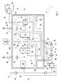
- Fig. 1 to 3 comprises a fuel cell system 1, which may preferably be arranged in a motor vehicle, at least one fuel cell 2 and a (first) Oxidatorboards worn 3.
- the fuel cell 2 is used in a conventional manner for generating electricity from a hydrogen gas-containing fuel gas and an oxygen gas-containing oxidant gas.
- the fuel gas is supplied to an anode side 4 of the fuel cell 2, while the oxidizer gas, which is expediently air, a cathode side 5 of the fuel cell 2 is supplied.
- an electrolyte 6 separates the anode side 4 from the cathode side 5.
- the fuel cell 2 usually consists of a stack of several fuel cell elements, in each of which the anode side 4 is separated from the cathode side 5 by an electrolyte 6.
- the fuel cell 2 to a high-temperature fuel cell, which may be configured in particular as a solid fuel cell or as an SOFC fuel cell.
- a low-temperature fuel cell which may be in particular a PEM fuel cell, which operates with a proton transport membrane or with a polymer electrolyte membrane as the electrolyte 6.
- the present invention is of particular importance for a high temperature fuel cell.
- the fuel cell 2 On the input side, the fuel cell 2 receives an anode gas formed by the fuel gas via an anode gas line 7 connected to the anode side 4. An anode exhaust gas containing hydrogen gas leaves the fuel cell 2 on the output side via an anode exhaust gas line 8, which is likewise connected to the anode side 4. Furthermore, the fuel cell 2 receives on the input side via a cathode gas line 9 connected to the cathode side 5 a cathode gas formed by the oxidizing gas. A cathode exhaust gas containing oxygen gas leaves the fuel cell 2 on the output side via a cathode exhaust gas line 10, which is connected to the cathode side 5 for this purpose.
- the first oxidizer supply device 3 is designed for supplying oxidizer gas, that is to say in particular of air, to the fuel cell 2.
- the first oxidizer supply device 3 has a (first) supply line 11, in which a suitable (first) conveying device 12, for example a pump or blower, for driving the oxidizing gas is arranged is.
- the first supply line 11 forms the cathode gas line 9 and thus leads the fuel cell 2 directly to the cathode gas.
- the fuel cell system 1 is also provided with a reformer 16 which serves to generate the fuel gas from a fuel and an oxidizer gas, preferably air.
- the reformer 16 is connected on the input side to a fuel line 17 and to an oxidizer line 18.
- a conveyor 19 for driving the fuel is arranged, e.g. a pump.
- the fuel is an atomic hydrogen-containing fuel, preferably a hydrocarbon.
- the oxidizer line 18 supplies the oxidizer gas to the reformer 16.
- a (second) oxidizer supply device 13 which contains a (second) supply device, eg a pump or a blower, in a (second) supply line 14.
- the second supply line 14 is branched off, namely into a first supply line branch 40 and a second supply line branch 41.
- the first supply line branch 40 here forms the oxidizer line 18 for supplying the reformer 16 Oxidizer.
- a valve device 42 may be provided which is specifically actuated via a corresponding controller 43 so that the respective required Oxidatorgasmenge through the respective supply line branch 40, 41 is eligible.
- the controller 43 is connected via appropriate control lines 44 with the controllable components of the fuel cell system 1 in a suitable manner.
- the fuel cell system 1 may further include a residual gas burner 20 configured to combust anode exhaust gas with cathode exhaust gas.
- the residual gas burner 20 is connected on the input side to the anode exhaust gas line 8 and to the cathode exhaust gas line 10.
- the residual gas burner 20 is equipped with a combustion chamber 21, in which a combustion reaction proceeds with an open flame.
- a residual gas burner 20 is also conceivable, which has an oxidation catalyst and works with catalytic combustion.
- an exhaust gas line 22 is connected to the residual gas burner 20, via which a burner exhaust gas formed by the combustion reaction is removed from the residual gas burner 20.
- a cooling gas line 23 may be connected to the residual gas burner 20, in particular on the cathode side. If necessary, a cooling gas, preferably air, can be fed to the residual gas burner 20 via the cooling gas line 23.
- a cooling gas preferably air
- the first Oxidatorboards concerned 3 supplies only the fuel cell 2 with oxidizer gas or cathode gas
- the second Oxidatormakerss couples 13 supplies the reformer 16 and the residual gas burner 20 with oxidizing gas or with cooling gas.
- a common Oxidatorsavings might be provided with oxidant gas, for example, the cathode gas line 9 may be formed by a third supply line branch, which also via the valve device 42 is controllable.
- the fuel cell system 1 may further comprise at least one heat exchanger.
- three heat exchangers are provided, namely a main heat exchanger 24, an additional heat exchanger 25 and a Rezirkulationskorübertrager 26.
- the main heat exchanger 24 is on the one hand in the exhaust pipe 22 and on the other hand integrated into the cathode gas line 9.
- the main heat exchanger 24 serves to transfer heat from the burner exhaust gas to the cathode gas.
- the additional heat exchanger 25 is on the one hand in the exhaust pipe 22 and on the other hand integrated into a conduit 27, which can lead to a basically any heat consumer.
- the additional heat exchanger 25 be integrated via line 27 into a cooling circuit of an internal combustion engine of the vehicle equipped with the fuel cell system 1 or in a heating circuit for warming up a vehicle interior of the equipped with the fuel cell system 1 vehicle.
- the additional heat exchanger 25 is arranged in the exhaust pipe 22 downstream of the main heat exchanger 24 and can extract additional heat from the burner exhaust gas.
- the recirculation heat exchanger 26 is bound on the one hand into the oxidizer gas line 18 or into the first supply line branch 40 and on the other hand into a recirculation line 28.
- the Rezirkulations Secureford trager 26 and the recirculation line 28 with the cathode gas line 9, in particular upstream of the Hauptnzoübertragers 24, couple heat transfer.
- the recirculation line 28 branches off at 29 from the anode exhaust gas line 8 and is connected to the input side of the reformer 16. It contains downstream of the recirculation heat 26 a conveyor 30 for driving the recirculated anode exhaust, which may be, for example, a pump, a blower or a compressor. Depending on the operating state of the fuel cell 2, the anode exhaust gas can contain a relatively high proportion of hydrogen gas and can thus be utilized by the return to the reformer 16 to increase the efficiency.
- Fuel cell 2 residual gas burner 20, main heat exchanger 24, additional heat exchanger 25 and Rezirkulationskorübertrager 26 form each separate in the examples shown Components. In principle, however, it is possible to structurally integrate at least two of these components into one unit.
- the residual gas burner 20 can be integrated into an output side of the fuel cell 2.
- the main heat exchanger 24 can be integrated into the outlet side of the residual gas burner 20. It is also possible to integrate two or three of these heat exchangers 24, 25, 26 into a structural unit.
- the fuel cell system 1 is also equipped with a thermally insulating insulating jacket 31, which preferably comprises a thermally insulating material.
- a thermally insulating jacket 31 which preferably comprises a thermally insulating material.
- it may be a sheet metal box, which is provided inside and / or outside with the insulation material.
- the enclosed or enveloped by the insulation sheath 31 volume forms an interior 32, which is used here for components of the fuel cell system 1 as an installation space.
- at least the fuel cell 2 and optionally at least one of the components reformer 16, residual gas burner 20, main heat exchanger 24, Rezirkulationstagetechniktrager 26, conveyor 30 are arranged in the interior 32.
- the reformer 16, the fuel cell 2, the residual gas burner 20 and the main heat exchanger 24 are arranged inside the insulation sheath 31, that is, in the interior space 32.
- the insulation sheath 31 consists of several partial sheaths.
- the interior 32 then consists of a plurality of part-internal spaces, which in particular communicate with each other.
- a such partial shell enclose at least the reformer 16, while another partial shell encloses at least the fuel cell 2 and the residual gas burner 20.
- the additional heat exchanger 25 and the recirculation heat exchanger 26 and the conveyors 12, 15, 19, 30 are arranged outside of the insulation sheath 31;
- the controller 43 is also expediently outside the insulation sheath 31st
- the insulation sheath 31 includes a plurality of through holes 33 through which the fuel pipe 17, the exhaust pipe 22, the recirculation pipe 28, the cooling gas pipe 23, and the cathode gas pipe 9 are passed through the insulation sheath 31.
- This implementation of said lines are carried out expedient so that the desired thermal insulation is ensured.
- a desired gas tightness and - if required - a desired pressure tightness can be achieved in the bushings.
- the associated passage opening 33 is designed such that at least the fuel line 17 can be connected directly to the reformer 16 without the fuel line 17 extending inside the interior 32.
- a portion of the reformer input side forms part of the insulation sheath 31.
- parts of the fuel cell system 1 run or lie outside of the insulation sheath 31, Such as sections of the supply lines 11, 14 and the recirculation line 28 and the Rezirkulationskorübertrager 26. Also conceivable is an embodiment in which said parts are arranged completely or at least substantially within the insulation sheath 31.
- the insulation sheath 31 also has two inlet openings, namely a first inlet opening 34 and a second inlet opening 35, through which oxidizing gas, ie preferably air, from an environment 36 of the fuel cell system 1 enters the interior 32 of the insulation sheath 31.
- the two inlet openings 34, 35 are each switchable by means of a valve 37 and 38, respectively.
- the valves 37, 38 are connected to the controller 43 in a suitable manner.
- Fig. 3 shows Fig. 3 another embodiment in which the insulating sheath 31 has at least one inlet opening 46, which may be associated with a non-return valve 47, which opens toward the interior 32 towards.
- the insulation sheath 31 has at least one outlet opening 39, to which, for example, the second supply line 14 is connected. Accordingly, the second oxidizer supply device 13 can suck the oxidizer gas through the outlet port 39 from the inner space 32. This will ensures a certain flushing of the interior 32, which prevents that within the interior 32, a critical concentration of fuel gas can arise, which can get into the interior 32 due to leaks.
- the outlet opening 39 may be associated with a non-return valve 45, which blocks towards the interior 32 and which may be arranged, for example, in the second supply line 14.
- the interior 32 forms part of a gas path, via which the reformer 16 is supplied with oxidizer gas.
- This can basically be used to preheat the oxidizer gas.
- the gas path in the interior 32 is specifically guided so that the oxidizer gas depending on the operating state of the fuel cell system 1 on the one hand the residual gas burner 20 and / or the main heat exchanger 24 and on the other hand the fuel cell 2 and / or the reformer 16 heat can escape when it flows through the interior 32.
- the temperature level of the oxidizer gas can be increased, which favors the operation of the fuel cell system 1.
- FIG. 1 shows Fig. 1
- the individual components of the fuel cell system 1 are cooled and have substantially the same temperature, namely preferably ambient temperature.
- the controller 43 actuates the valves 37, 38 associated with the intake ports 34, 35 so that the first intake port 34 is opened while the second intake port 35 is locked.
- the oxidizer gas is thus sucked into the inner space 32 exclusively via the first inlet opening 34.
- flow guide elements 48 are arranged, which guide the gas path in the interior 32 so that the residual gas burner 22 and here the main heat exchanger 24 is flowed by the sucked oxidizer gas or flows around before it leaves the interior 32 again via the outlet opening 39.
- a corresponding flow situation is in Fig.
- the residual gas burner 20 heats up much faster than the fuel cell 2 and the reformer 16. Accordingly, can be withdrawn by the application of the residual gas burner 20 with oxidant gas to the residual gas burner 20 heat that can be used to preheat the oxidizer gas. Since the main heat exchanger 24 directly adjoins the residual gas burner 20, and the main heat exchanger 24 is heated comparatively quickly, so that the flow around the main heat exchanger 24 can be used to increase the temperature of the oxidizing gas.
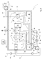
- Fig. 2 now shows a normal operating state or a warm start operating state of the fuel cell system 1.
- the controller 23 actuates the valves 37, 38 so that the first inlet opening 34 is blocked is while the second inlet port 35 is opened.
- This switching position can also be realized for the normal operating state of the fuel cell system 1. In this switching position, the oxidant gas is thus sucked exclusively through the second inlet opening 35, whereby, in particular in conjunction with the flow guide elements 48, a targeted flow and flow around the fuel cell 2 and here also the reformer 16 can form.
- the oxidizer gas can absorb heat from the reformer 16 and from the fuel cell 2, which raises the temperature level of the oxidizer gas.
- the time until reaching the operating temperature of the fuel cell 2 can thereby be shortened.
- the fuel cell 2 can be cooled by this flow guide, as well as the reformer 16th
- Fig. 3 an embodiment in which the location for the inlet of the oxidizer gas or the guidance of the oxidizer gas within the insulation sheath 31 is not controllable.
- the gas path in the interior space 31 is specifically designed such that the oxidizing gas flowing in via the at least one inlet opening 46 both is coupled to the fuel cell 2 and the residual gas burner 20 to transmit heat.
- the inflowing oxidizer gas is additionally coupled in a heat-transmitting manner to the reformer 16 and / or to the main heat exchanger 24.
- Such a flow or flow around the said components can also be realized by means of flow guide elements 48.
- This embodiment is characterized in that during the cold start operation, the arrival or flow around the residual gas burner 20 and possibly the Haupttownauertragers 24 can significantly increase the temperature level of the oxidizer gas.
- a temperature increase in the oxidant gas or a cooling for the reformer 16 and the fuel cell 2 can also be achieved during the warm start operation or during normal operation by the arrival or flow around the fuel cell 2 and optionally the reformer 16.
- the embodiment shown operates less efficiently than that in FIGS Fig. 1 and 2 shown embodiment, but is feasible with a reduced effort.
- the first oxidizer supply device 3 can directly suck in the oxidizer gas or the cathode gas from the environment 36.
- the first oxidizer supply device 3 sucks the cathode gas out of the interior 32 of the insulation sheath 31.
- the first supply line 11 is then connected on the input side to the outlet opening 39.
- an embodiment is conceivable in which only the first supply line 11 is connected to the outlet opening 39 and in which the second oxidizer supply device 13 directly sucks the oxidizer gas from the environment 36.
Applications Claiming Priority (1)
| Application Number | Priority Date | Filing Date | Title |
|---|---|---|---|
| DE102007039017A DE102007039017A1 (de) | 2007-08-17 | 2007-08-17 | Brennstoffzellensystem |
Publications (2)
| Publication Number | Publication Date |
|---|---|
| EP2028709A1 true EP2028709A1 (fr) | 2009-02-25 |
| EP2028709B1 EP2028709B1 (fr) | 2011-10-19 |
Family
ID=39930814
Family Applications (1)
| Application Number | Title | Priority Date | Filing Date |
|---|---|---|---|
| EP08162157A Active EP2028709B1 (fr) | 2007-08-17 | 2008-08-11 | Système de pile à combustible |
Country Status (3)
| Country | Link |
|---|---|
| EP (1) | EP2028709B1 (fr) |
| AT (1) | ATE529912T1 (fr) |
| DE (1) | DE102007039017A1 (fr) |
Cited By (1)
| Publication number | Priority date | Publication date | Assignee | Title |
|---|---|---|---|---|
| EP2963725A1 (fr) * | 2014-06-30 | 2016-01-06 | Aisin Seiki Kabushiki Kaisha | Système de pile à combustible |
Families Citing this family (3)
| Publication number | Priority date | Publication date | Assignee | Title |
|---|---|---|---|---|
| CN102035002B (zh) * | 2010-11-30 | 2013-01-30 | 新源动力股份有限公司 | 一种具有水热管理能力的燃料电池模块 |
| AT523668B1 (de) * | 2020-03-30 | 2021-12-15 | Avl List Gmbh | Brennstoffzellensystem und Verfahren zum Betreiben eines Brennstoffzellensystems |
| DE102021214812A1 (de) | 2021-12-21 | 2023-06-22 | Robert Bosch Gesellschaft mit beschränkter Haftung | Brennstoffzellenvorrichtung |
Citations (6)
| Publication number | Priority date | Publication date | Assignee | Title |
|---|---|---|---|---|
| EP0374636A1 (fr) * | 1988-12-20 | 1990-06-27 | Asea Brown Boveri Ag | Procédé de conversion de l'énergie disponible dans un matériau sous forme de potentiel chimique en énergie électrique par un procédé électrochimique à haute température |
| EP0654838A1 (fr) * | 1993-11-24 | 1995-05-24 | Sulzer Innotec Ag | Dispositif comportant des piles à combustible fonctionnant à haute température et méthode de son démarrage |
| DE4446841A1 (de) * | 1994-12-27 | 1996-07-04 | Mtu Friedrichshafen Gmbh | Brennstoffzellenmodul |
| DE19910695C1 (de) * | 1999-03-10 | 2000-08-10 | Siemens Ag | Verfahren zum Betreiben einer Brennstoffzellenanlage und Brennstoffzellenanlage |
| EP1347529A2 (fr) * | 2002-03-19 | 2003-09-24 | Sulzer Hexis AG | Batterie de cellules à combustible avec un échangeur de chaleur intégré |
| EP1624516A1 (fr) | 2004-08-02 | 2006-02-08 | Siemens Aktiengesellschaft | Méthode de fonctionnement d'une pile a combustible placée dans un logement et dispositif pour mettre en oeuvre le procédé |
Family Cites Families (2)
| Publication number | Priority date | Publication date | Assignee | Title |
|---|---|---|---|---|
| AT407590B (de) * | 1998-10-08 | 2001-04-25 | Vaillant Gmbh | Blockheizkraftwerk |
| DE102006031866A1 (de) * | 2006-07-10 | 2008-01-17 | Webasto Ag | Brennstoffzellensystem und Verfahren zum Beeinflussen des Wärmehaushaltes eines Brennstoffzellensystems |
-
2007
- 2007-08-17 DE DE102007039017A patent/DE102007039017A1/de not_active Withdrawn
-
2008
- 2008-08-11 AT AT08162157T patent/ATE529912T1/de active
- 2008-08-11 EP EP08162157A patent/EP2028709B1/fr active Active
Patent Citations (6)
| Publication number | Priority date | Publication date | Assignee | Title |
|---|---|---|---|---|
| EP0374636A1 (fr) * | 1988-12-20 | 1990-06-27 | Asea Brown Boveri Ag | Procédé de conversion de l'énergie disponible dans un matériau sous forme de potentiel chimique en énergie électrique par un procédé électrochimique à haute température |
| EP0654838A1 (fr) * | 1993-11-24 | 1995-05-24 | Sulzer Innotec Ag | Dispositif comportant des piles à combustible fonctionnant à haute température et méthode de son démarrage |
| DE4446841A1 (de) * | 1994-12-27 | 1996-07-04 | Mtu Friedrichshafen Gmbh | Brennstoffzellenmodul |
| DE19910695C1 (de) * | 1999-03-10 | 2000-08-10 | Siemens Ag | Verfahren zum Betreiben einer Brennstoffzellenanlage und Brennstoffzellenanlage |
| EP1347529A2 (fr) * | 2002-03-19 | 2003-09-24 | Sulzer Hexis AG | Batterie de cellules à combustible avec un échangeur de chaleur intégré |
| EP1624516A1 (fr) | 2004-08-02 | 2006-02-08 | Siemens Aktiengesellschaft | Méthode de fonctionnement d'une pile a combustible placée dans un logement et dispositif pour mettre en oeuvre le procédé |
Cited By (2)
| Publication number | Priority date | Publication date | Assignee | Title |
|---|---|---|---|---|
| EP2963725A1 (fr) * | 2014-06-30 | 2016-01-06 | Aisin Seiki Kabushiki Kaisha | Système de pile à combustible |
| JP2016012531A (ja) * | 2014-06-30 | 2016-01-21 | アイシン精機株式会社 | 燃料電池システム |
Also Published As
| Publication number | Publication date |
|---|---|
| EP2028709B1 (fr) | 2011-10-19 |
| ATE529912T1 (de) | 2011-11-15 |
| DE102007039017A1 (de) | 2009-02-19 |
Similar Documents
| Publication | Publication Date | Title |
|---|---|---|
| EP1616361B1 (fr) | Dispositif de conversion de l'energie avec installation de reformage et installation de pile a combustible associees | |
| EP1679757B1 (fr) | Système de pile à combustible | |
| DE19931061A1 (de) | Anordnung zum Beheizen/Kühlen einer Brennstoffzelle und Brennstoffzellensystem | |
| DE102011088563B4 (de) | Anordnung mit Brennstoffzellensystem | |
| DE102008018152B4 (de) | Brennstoffzellensystem und zugehöriges Betriebsverfahren | |
| EP2028709B1 (fr) | Système de pile à combustible | |
| EP1947723B1 (fr) | Système d'approvisionnement d'énergie | |
| EP1986263B1 (fr) | Système de cellules combustibles et procédé de démarrage correspondant | |
| EP2058885B1 (fr) | Système de cellules combustibles | |
| DE19931062B4 (de) | Anordnung zum Beheizen/Kühlen einer Brennstoffzelle und Brennstoffzellensystem und deren Verwendung | |
| EP2033251A1 (fr) | Système à pile à combustible | |
| DE102012220082B4 (de) | Fahrzeugbrennstoffzellensystem und zugehöriges Betriebsverfahren | |
| DE102008008907B4 (de) | Brennstoffzellensystem | |
| DE102006017615A1 (de) | Brennstoffzellensytem | |
| DE202006008898U1 (de) | Brennstoffzellensystem für ein Fahrzeug | |
| DE102005030474A1 (de) | Brennstoffzellensystem für ein Fahrzeug | |
| EP1968150B1 (fr) | Système de piles à combustibles | |
| EP1845577B1 (fr) | Système de pile à combustible | |
| DE102014115096A1 (de) | System zur versorgung eines fahrzeugs mit elektrischer energie | |
| DE102021126708B3 (de) | Verfahren zum Starten einer Festoxidbrennstoffzellenvorrichtung sowie Brennstoffzellenfahrzeug | |
| DE102007054768A1 (de) | Reformer, Brennstoffzelle und zugehörige Betriebsverfahren | |
| EP2075225B1 (fr) | Dispositif de reformage, système de piles à combustibles et procédé d'opération du système | |
| DE112019005805T5 (de) | Kompakte Brenner/Reformer-Einheit für ein Brennstoffzellensystem sowie deren Verwendung und Funktionsweise | |
| DE102007040192A1 (de) | Reformer und Brennstoffzellensystem |
Legal Events
| Date | Code | Title | Description |
|---|---|---|---|
| PUAI | Public reference made under article 153(3) epc to a published international application that has entered the european phase |
Free format text: ORIGINAL CODE: 0009012 |
|
| AK | Designated contracting states |
Kind code of ref document: A1 Designated state(s): AT BE BG CH CY CZ DE DK EE ES FI FR GB GR HR HU IE IS IT LI LT LU LV MC MT NL NO PL PT RO SE SI SK TR |
|
| AX | Request for extension of the european patent |
Extension state: AL BA MK RS |
|
| AKX | Designation fees paid |
Designated state(s): AT BE BG CH CY CZ DE DK EE ES FI FR GB GR HR HU IE IS IT LI LT LU LV MC MT NL NO PL PT RO SE SI SK TR |
|
| 17P | Request for examination filed |
Effective date: 20090825 |
|
| 17Q | First examination report despatched |
Effective date: 20100312 |
|
| GRAP | Despatch of communication of intention to grant a patent |
Free format text: ORIGINAL CODE: EPIDOSNIGR1 |
|
| GRAS | Grant fee paid |
Free format text: ORIGINAL CODE: EPIDOSNIGR3 |
|
| GRAA | (expected) grant |
Free format text: ORIGINAL CODE: 0009210 |
|
| AK | Designated contracting states |
Kind code of ref document: B1 Designated state(s): AT BE BG CH CY CZ DE DK EE ES FI FR GB GR HR HU IE IS IT LI LT LU LV MC MT NL NO PL PT RO SE SI SK TR |
|
| REG | Reference to a national code |
Ref country code: GB Ref legal event code: FG4D Free format text: NOT ENGLISH |
|
| REG | Reference to a national code |
Ref country code: CH Ref legal event code: EP |
|
| REG | Reference to a national code |
Ref country code: IE Ref legal event code: FG4D |
|
| REG | Reference to a national code |
Ref country code: DE Ref legal event code: R096 Ref document number: 502008005242 Country of ref document: DE Effective date: 20120126 |
|
| REG | Reference to a national code |
Ref country code: NL Ref legal event code: VDEP Effective date: 20111019 |
|
| LTIE | Lt: invalidation of european patent or patent extension |
Effective date: 20111019 |
|
| PG25 | Lapsed in a contracting state [announced via postgrant information from national office to epo] |
Ref country code: NO Free format text: LAPSE BECAUSE OF FAILURE TO SUBMIT A TRANSLATION OF THE DESCRIPTION OR TO PAY THE FEE WITHIN THE PRESCRIBED TIME-LIMIT Effective date: 20120119 Ref country code: IS Free format text: LAPSE BECAUSE OF FAILURE TO SUBMIT A TRANSLATION OF THE DESCRIPTION OR TO PAY THE FEE WITHIN THE PRESCRIBED TIME-LIMIT Effective date: 20120219 Ref country code: LT Free format text: LAPSE BECAUSE OF FAILURE TO SUBMIT A TRANSLATION OF THE DESCRIPTION OR TO PAY THE FEE WITHIN THE PRESCRIBED TIME-LIMIT Effective date: 20111019 |
|
| REG | Reference to a national code |
Ref country code: IE Ref legal event code: FD4D |
|
| PG25 | Lapsed in a contracting state [announced via postgrant information from national office to epo] |
Ref country code: NL Free format text: LAPSE BECAUSE OF FAILURE TO SUBMIT A TRANSLATION OF THE DESCRIPTION OR TO PAY THE FEE WITHIN THE PRESCRIBED TIME-LIMIT Effective date: 20111019 Ref country code: GR Free format text: LAPSE BECAUSE OF FAILURE TO SUBMIT A TRANSLATION OF THE DESCRIPTION OR TO PAY THE FEE WITHIN THE PRESCRIBED TIME-LIMIT Effective date: 20120120 Ref country code: PT Free format text: LAPSE BECAUSE OF FAILURE TO SUBMIT A TRANSLATION OF THE DESCRIPTION OR TO PAY THE FEE WITHIN THE PRESCRIBED TIME-LIMIT Effective date: 20120220 Ref country code: SE Free format text: LAPSE BECAUSE OF FAILURE TO SUBMIT A TRANSLATION OF THE DESCRIPTION OR TO PAY THE FEE WITHIN THE PRESCRIBED TIME-LIMIT Effective date: 20111019 Ref country code: LV Free format text: LAPSE BECAUSE OF FAILURE TO SUBMIT A TRANSLATION OF THE DESCRIPTION OR TO PAY THE FEE WITHIN THE PRESCRIBED TIME-LIMIT Effective date: 20111019 Ref country code: HR Free format text: LAPSE BECAUSE OF FAILURE TO SUBMIT A TRANSLATION OF THE DESCRIPTION OR TO PAY THE FEE WITHIN THE PRESCRIBED TIME-LIMIT Effective date: 20111019 Ref country code: SI Free format text: LAPSE BECAUSE OF FAILURE TO SUBMIT A TRANSLATION OF THE DESCRIPTION OR TO PAY THE FEE WITHIN THE PRESCRIBED TIME-LIMIT Effective date: 20111019 |
|
| PG25 | Lapsed in a contracting state [announced via postgrant information from national office to epo] |
Ref country code: CY Free format text: LAPSE BECAUSE OF FAILURE TO SUBMIT A TRANSLATION OF THE DESCRIPTION OR TO PAY THE FEE WITHIN THE PRESCRIBED TIME-LIMIT Effective date: 20111019 |
|
| PG25 | Lapsed in a contracting state [announced via postgrant information from national office to epo] |
Ref country code: CZ Free format text: LAPSE BECAUSE OF FAILURE TO SUBMIT A TRANSLATION OF THE DESCRIPTION OR TO PAY THE FEE WITHIN THE PRESCRIBED TIME-LIMIT Effective date: 20111019 Ref country code: EE Free format text: LAPSE BECAUSE OF FAILURE TO SUBMIT A TRANSLATION OF THE DESCRIPTION OR TO PAY THE FEE WITHIN THE PRESCRIBED TIME-LIMIT Effective date: 20111019 Ref country code: DK Free format text: LAPSE BECAUSE OF FAILURE TO SUBMIT A TRANSLATION OF THE DESCRIPTION OR TO PAY THE FEE WITHIN THE PRESCRIBED TIME-LIMIT Effective date: 20111019 Ref country code: SK Free format text: LAPSE BECAUSE OF FAILURE TO SUBMIT A TRANSLATION OF THE DESCRIPTION OR TO PAY THE FEE WITHIN THE PRESCRIBED TIME-LIMIT Effective date: 20111019 Ref country code: BG Free format text: LAPSE BECAUSE OF FAILURE TO SUBMIT A TRANSLATION OF THE DESCRIPTION OR TO PAY THE FEE WITHIN THE PRESCRIBED TIME-LIMIT Effective date: 20120119 Ref country code: IE Free format text: LAPSE BECAUSE OF FAILURE TO SUBMIT A TRANSLATION OF THE DESCRIPTION OR TO PAY THE FEE WITHIN THE PRESCRIBED TIME-LIMIT Effective date: 20111019 |
|
| PLBE | No opposition filed within time limit |
Free format text: ORIGINAL CODE: 0009261 |
|
| STAA | Information on the status of an ep patent application or granted ep patent |
Free format text: STATUS: NO OPPOSITION FILED WITHIN TIME LIMIT |
|
| PG25 | Lapsed in a contracting state [announced via postgrant information from national office to epo] |
Ref country code: RO Free format text: LAPSE BECAUSE OF FAILURE TO SUBMIT A TRANSLATION OF THE DESCRIPTION OR TO PAY THE FEE WITHIN THE PRESCRIBED TIME-LIMIT Effective date: 20111019 Ref country code: PL Free format text: LAPSE BECAUSE OF FAILURE TO SUBMIT A TRANSLATION OF THE DESCRIPTION OR TO PAY THE FEE WITHIN THE PRESCRIBED TIME-LIMIT Effective date: 20111019 Ref country code: IT Free format text: LAPSE BECAUSE OF FAILURE TO SUBMIT A TRANSLATION OF THE DESCRIPTION OR TO PAY THE FEE WITHIN THE PRESCRIBED TIME-LIMIT Effective date: 20111019 |
|
| 26N | No opposition filed |
Effective date: 20120720 |
|
| REG | Reference to a national code |
Ref country code: DE Ref legal event code: R097 Ref document number: 502008005242 Country of ref document: DE Effective date: 20120720 |
|
| BERE | Be: lapsed |
Owner name: J. EBERSPACHER G.M.B.H. & CO. KG Effective date: 20120831 |
|
| REG | Reference to a national code |
Ref country code: CH Ref legal event code: PL |
|
| PG25 | Lapsed in a contracting state [announced via postgrant information from national office to epo] |
Ref country code: MC Free format text: LAPSE BECAUSE OF NON-PAYMENT OF DUE FEES Effective date: 20120831 |
|
| PG25 | Lapsed in a contracting state [announced via postgrant information from national office to epo] |
Ref country code: CH Free format text: LAPSE BECAUSE OF NON-PAYMENT OF DUE FEES Effective date: 20120831 Ref country code: LI Free format text: LAPSE BECAUSE OF NON-PAYMENT OF DUE FEES Effective date: 20120831 Ref country code: ES Free format text: LAPSE BECAUSE OF FAILURE TO SUBMIT A TRANSLATION OF THE DESCRIPTION OR TO PAY THE FEE WITHIN THE PRESCRIBED TIME-LIMIT Effective date: 20120130 |
|
| PG25 | Lapsed in a contracting state [announced via postgrant information from national office to epo] |
Ref country code: BE Free format text: LAPSE BECAUSE OF NON-PAYMENT OF DUE FEES Effective date: 20120831 |
|
| PG25 | Lapsed in a contracting state [announced via postgrant information from national office to epo] |
Ref country code: FI Free format text: LAPSE BECAUSE OF FAILURE TO SUBMIT A TRANSLATION OF THE DESCRIPTION OR TO PAY THE FEE WITHIN THE PRESCRIBED TIME-LIMIT Effective date: 20111019 |
|
| PG25 | Lapsed in a contracting state [announced via postgrant information from national office to epo] |
Ref country code: MT Free format text: LAPSE BECAUSE OF FAILURE TO SUBMIT A TRANSLATION OF THE DESCRIPTION OR TO PAY THE FEE WITHIN THE PRESCRIBED TIME-LIMIT Effective date: 20111019 |
|
| REG | Reference to a national code |
Ref country code: FR Ref legal event code: CD Owner name: EBERSPACHER CLIMATE CONTROL SYSTEMS GMBH & CO. KG Effective date: 20131129 |
|
| REG | Reference to a national code |
Ref country code: DE Ref legal event code: R082 Ref document number: 502008005242 Country of ref document: DE Representative=s name: BRP RENAUD UND PARTNER MBB, DE Effective date: 20131212 Ref country code: DE Ref legal event code: R082 Ref document number: 502008005242 Country of ref document: DE Representative=s name: BRP RENAUD UND PARTNER MBB RECHTSANWAELTE PATE, DE Effective date: 20131212 Ref country code: DE Ref legal event code: R082 Ref document number: 502008005242 Country of ref document: DE Representative=s name: BRP RENAUD & PARTNER, DE Effective date: 20131212 Ref country code: DE Ref legal event code: R081 Ref document number: 502008005242 Country of ref document: DE Owner name: EBERSPAECHER CLIMATE CONTROL SYSTEMS GMBH & CO, DE Free format text: FORMER OWNER: J. EBERSPAECHER GMBH & CO. KG, 73730 ESSLINGEN, DE Effective date: 20131212 |
|
| REG | Reference to a national code |
Ref country code: FR Ref legal event code: TP Owner name: EBERSPACHER EXHAUST TECHNOLOGY GMBH & CO. KG, DE Effective date: 20140204 |
|
| PG25 | Lapsed in a contracting state [announced via postgrant information from national office to epo] |
Ref country code: TR Free format text: LAPSE BECAUSE OF FAILURE TO SUBMIT A TRANSLATION OF THE DESCRIPTION OR TO PAY THE FEE WITHIN THE PRESCRIBED TIME-LIMIT Effective date: 20111019 |
|
| PG25 | Lapsed in a contracting state [announced via postgrant information from national office to epo] |
Ref country code: LU Free format text: LAPSE BECAUSE OF NON-PAYMENT OF DUE FEES Effective date: 20120811 |
|
| PG25 | Lapsed in a contracting state [announced via postgrant information from national office to epo] |
Ref country code: HU Free format text: LAPSE BECAUSE OF FAILURE TO SUBMIT A TRANSLATION OF THE DESCRIPTION OR TO PAY THE FEE WITHIN THE PRESCRIBED TIME-LIMIT Effective date: 20080811 |
|
| REG | Reference to a national code |
Ref country code: AT Ref legal event code: MM01 Ref document number: 529912 Country of ref document: AT Kind code of ref document: T Effective date: 20130811 |
|
| PG25 | Lapsed in a contracting state [announced via postgrant information from national office to epo] |
Ref country code: AT Free format text: LAPSE BECAUSE OF NON-PAYMENT OF DUE FEES Effective date: 20130811 |
|
| REG | Reference to a national code |
Ref country code: FR Ref legal event code: TP Owner name: EBERSPACHER CLIMATE CONTROL SYSTEMS GMBH & CO., DE Effective date: 20150416 |
|
| REG | Reference to a national code |
Ref country code: FR Ref legal event code: PLFP Year of fee payment: 9 |
|
| REG | Reference to a national code |
Ref country code: FR Ref legal event code: PLFP Year of fee payment: 10 |
|
| REG | Reference to a national code |
Ref country code: FR Ref legal event code: PLFP Year of fee payment: 11 |
|
| PGFP | Annual fee paid to national office [announced via postgrant information from national office to epo] |
Ref country code: GB Payment date: 20220824 Year of fee payment: 15 |
|
| PGFP | Annual fee paid to national office [announced via postgrant information from national office to epo] |
Ref country code: FR Payment date: 20220822 Year of fee payment: 15 |
|
| PGFP | Annual fee paid to national office [announced via postgrant information from national office to epo] |
Ref country code: DE Payment date: 20230822 Year of fee payment: 16 |
|
| GBPC | Gb: european patent ceased through non-payment of renewal fee |
Effective date: 20230811 |