EP2028653A1 - Masque de phase pour stockage de données holographiques - Google Patents
Masque de phase pour stockage de données holographiques Download PDFInfo
- Publication number
- EP2028653A1 EP2028653A1 EP07114691A EP07114691A EP2028653A1 EP 2028653 A1 EP2028653 A1 EP 2028653A1 EP 07114691 A EP07114691 A EP 07114691A EP 07114691 A EP07114691 A EP 07114691A EP 2028653 A1 EP2028653 A1 EP 2028653A1
- Authority
- EP
- European Patent Office
- Prior art keywords
- phase
- phase mask
- mask
- cells
- size
- Prior art date
- Legal status (The legal status is an assumption and is not a legal conclusion. Google has not performed a legal analysis and makes no representation as to the accuracy of the status listed.)
- Withdrawn
Links
- 238000013500 data storage Methods 0.000 title claims abstract description 11
- 238000000034 method Methods 0.000 claims abstract description 3
- 230000010363 phase shift Effects 0.000 claims description 20
- 230000003287 optical effect Effects 0.000 claims description 12
- 238000005286 illumination Methods 0.000 description 3
- 230000001427 coherent effect Effects 0.000 description 2
- 238000003384 imaging method Methods 0.000 description 1
- 239000011159 matrix material Substances 0.000 description 1
- 238000012986 modification Methods 0.000 description 1
- 230000004048 modification Effects 0.000 description 1
- 238000001228 spectrum Methods 0.000 description 1
- 239000011232 storage material Substances 0.000 description 1
Images


Classifications
-
- G—PHYSICS
- G03—PHOTOGRAPHY; CINEMATOGRAPHY; ANALOGOUS TECHNIQUES USING WAVES OTHER THAN OPTICAL WAVES; ELECTROGRAPHY; HOLOGRAPHY
- G03H—HOLOGRAPHIC PROCESSES OR APPARATUS
- G03H1/00—Holographic processes or apparatus using light, infrared or ultraviolet waves for obtaining holograms or for obtaining an image from them; Details peculiar thereto
- G03H1/04—Processes or apparatus for producing holograms
- G03H1/16—Processes or apparatus for producing holograms using Fourier transform
-
- G—PHYSICS
- G11—INFORMATION STORAGE
- G11B—INFORMATION STORAGE BASED ON RELATIVE MOVEMENT BETWEEN RECORD CARRIER AND TRANSDUCER
- G11B7/00—Recording or reproducing by optical means, e.g. recording using a thermal beam of optical radiation by modifying optical properties or the physical structure, reproducing using an optical beam at lower power by sensing optical properties; Record carriers therefor
- G11B7/004—Recording, reproducing or erasing methods; Read, write or erase circuits therefor
- G11B7/0065—Recording, reproducing or erasing by using optical interference patterns, e.g. holograms
-
- G—PHYSICS
- G03—PHOTOGRAPHY; CINEMATOGRAPHY; ANALOGOUS TECHNIQUES USING WAVES OTHER THAN OPTICAL WAVES; ELECTROGRAPHY; HOLOGRAPHY
- G03H—HOLOGRAPHIC PROCESSES OR APPARATUS
- G03H1/00—Holographic processes or apparatus using light, infrared or ultraviolet waves for obtaining holograms or for obtaining an image from them; Details peculiar thereto
- G03H1/04—Processes or apparatus for producing holograms
- G03H1/18—Particular processing of hologram record carriers, e.g. for obtaining blazed holograms
-
- G—PHYSICS
- G03—PHOTOGRAPHY; CINEMATOGRAPHY; ANALOGOUS TECHNIQUES USING WAVES OTHER THAN OPTICAL WAVES; ELECTROGRAPHY; HOLOGRAPHY
- G03H—HOLOGRAPHIC PROCESSES OR APPARATUS
- G03H1/00—Holographic processes or apparatus using light, infrared or ultraviolet waves for obtaining holograms or for obtaining an image from them; Details peculiar thereto
- G03H1/22—Processes or apparatus for obtaining an optical image from holograms
-
- G—PHYSICS
- G11—INFORMATION STORAGE
- G11B—INFORMATION STORAGE BASED ON RELATIVE MOVEMENT BETWEEN RECORD CARRIER AND TRANSDUCER
- G11B7/00—Recording or reproducing by optical means, e.g. recording using a thermal beam of optical radiation by modifying optical properties or the physical structure, reproducing using an optical beam at lower power by sensing optical properties; Record carriers therefor
- G11B7/12—Heads, e.g. forming of the optical beam spot or modulation of the optical beam
- G11B7/125—Optical beam sources therefor, e.g. laser control circuitry specially adapted for optical storage devices; Modulators, e.g. means for controlling the size or intensity of optical spots or optical traces
- G11B7/128—Modulators
-
- G—PHYSICS
- G11—INFORMATION STORAGE
- G11B—INFORMATION STORAGE BASED ON RELATIVE MOVEMENT BETWEEN RECORD CARRIER AND TRANSDUCER
- G11B7/00—Recording or reproducing by optical means, e.g. recording using a thermal beam of optical radiation by modifying optical properties or the physical structure, reproducing using an optical beam at lower power by sensing optical properties; Record carriers therefor
- G11B7/24—Record carriers characterised by shape, structure or physical properties, or by the selection of the material
- G11B7/26—Apparatus or processes specially adapted for the manufacture of record carriers
-
- G—PHYSICS
- G11—INFORMATION STORAGE
- G11C—STATIC STORES
- G11C13/00—Digital stores characterised by the use of storage elements not covered by groups G11C11/00, G11C23/00, or G11C25/00
- G11C13/04—Digital stores characterised by the use of storage elements not covered by groups G11C11/00, G11C23/00, or G11C25/00 using optical elements ; using other beam accessed elements, e.g. electron or ion beam
- G11C13/042—Digital stores characterised by the use of storage elements not covered by groups G11C11/00, G11C23/00, or G11C25/00 using optical elements ; using other beam accessed elements, e.g. electron or ion beam using information stored in the form of interference pattern
Definitions
- the present invention relates to a phase mask for holographic data storage, and to a method and an apparatus for reading from and/or writing to holographic storage media using such a phase mask.
- holographic data storage digital data are stored by recording the interference pattern produced by the superposition of two coherent laser beams, where one beam, the so-called 'object beam', is modulated by a spatial light modulator (SLM) and carries the information to be recorded.
- the second beam serves as a reference beam.
- the interference pattern leads to modifications of specific properties of the storage material, which depend on the local intensity of the interference pattern. Reading of a recorded hologram is performed by illuminating the hologram with the reference beam using the same conditions as during recording. This results in the reconstruction of the recorded object beam.
- holographic data storage is an increased data capacity. Contrary to conventional optical storage media, the volume of the holographic storage medium is used for storing information, not just a few layers.
- One further advantage of holographic data storage is the possibility to store multiple data in the same volume, e.g. by changing the angle between the two beams or by using shift multiplexing, etc.
- data are stored as data pages.
- a data page consists of a matrix of light-dark-patterns, i.e. a two dimensional binary array or an array of grey values, which code multiple bits. This allows to achieve increased data rates in addition to the increased storage density.
- the data page is imprinted onto the object beam by the spatial light modulator and detected with an array detector.
- a pixelated spatial light modulator is used for modulating the object beam intensity with information.
- This intensity distribution is usually Fourier transformed by an objective lens.
- the Fourier transform i.e. the spectrum of a pixelated data pattern has a high central intensity peak, hereafter referred to as DC-peak.
- the actual information is distributed around this peak on a much lower level, typically -60dB.
- the DC-peak of the object beam can cause an undesired saturation of the photosensitive medium.
- the envelope of the surrounding intensity distribution can be described by a 2-dimensional sinc-function (sin(x)/x ), which results from the usual square-like shape of the pixels.
- the full information about the SLM pixel pattern is located below the so-called Nyquist limit which lies at half the distance to the first zero of the sinc-function.
- phase modulation in addition to the intensity modulation.
- M. J. O'Callaghan "Sorting through the lore of phase mask options - performance measures and practical commercial designs", Proc. SPIE Vol. 5362 (2004), pp. 150-159 .
- a binary phase mask is used for this purpose, which introduces a phase shift of 0 or ⁇ with respect to the laser wavelength.
- the phase cells i.e. the areas with constant phase, have a size of one or more pixels of the SLM.
- the spatial distribution of 0 and ⁇ cells is random or pseudo random, the total number of 0 and ⁇ cells is essentially the same.
- a phase mask with a cell size of one SLM pixel suppresses the DC-peak quite well. However, a large fraction of intensity is still located above the Nyquist limit. This fraction is redundant and does not contain necessary data information. Furthermore, because of the sinc-like envelope, the intensity distribution is not flat within the central region of the Fourier plane or in the holographic medium, respectively.
- phase mask having a phase modulation with a lower spatial resolution than the SLM.
- phase mask lead to a narrower intensity distribution in the Fourier plane. Therefore, it reduces the unnecessary intensity above the Nyquist limit, whereas the important intensity below the Nyquist limit is increased.
- phase mask for holographic data storage having a plurality of phase cells, wherein the phase cells have a phase variation on sub-cell scale.
- the invention proposes to apply a special phase distribution within each phase cell. If the cell size is the same as the SLM pixel size, this means a phase variation on a sub-pixel scale.
- the special phase distribution on sub-cell scale affects the intensity distribution in the Fourier plane in such way that its envelope becomes flatter. As a consequence the illumination of the holographic storage medium is more balanced and a possible saturation is avoided. This allows to achieve stronger holograms with a better signal-to-noise ratio (SNR) or a larger number of multiplexed holograms, i.e. an increased capacity.
- SNR signal-to-noise ratio
- the size of the phase cells is equal to an integer multiple of the size of the pixels of the SLM.
- the size of the phase cells is increased to an integer multiple of the SLM pixel size, for example if one phase cell is associated to four SLM pixels, the intensity above the Nyquist limit is reduced, whereas the intensity below the Nyquist limit is increased. This further improves the illumination of the holographic storage medium.
- the size of the phase cells is preferably identical in perpendicular directions within the plane of the phase mask, e.g. each phase cell is associated to 2 ⁇ 2, 3 ⁇ 3, etc. SLM pixels. Of course, it is likewise possible to use different sizes in both directions, e.g. 1 ⁇ 2, 2 ⁇ 3, etc. SLM pixels.
- a special pattern of the phase variation is at least one of a circular, rectangular, ring-like, polygon-like, or pixelated pattern, or a combination of these patterns.
- Such patterns offer the advantage that they can be relatively easy manufactured.
- different phase cells can have different phase variations, i.e. different patterns.
- the phase variation is inverse for half the number of phase cells. This solution automatically ensures a balanced occurrence of ⁇ and 0 phase shifts. It is likewise feasible that the inverse pattern differs from the regular pattern.
- the phase mask introduces a binary or a multi level phase shift.
- the spatial distribution of 0 and ⁇ cells is random or pseudo random.
- the spatial distribution of phase cells with different patterns is random or pseudo random.
- the phase mask is a transparent optical element with a varying surface height or a varying refractive index. This allows to generate the necessary phase shifts very easily.
- the phase mask is a reflective optical element with a varying surface height. This is especially useful when a reflective element is needed in the optical path anyway.
- the phase mask has a switchable phase distribution or switchable phase shifts.
- the phase mask can be adapted to different types of holographic storage media, or to different operating conditions.
- an apparatus for reading from and/or writing to holographic storage media includes a phase mask according to the invention in an optical path of an object beam.
- Such an apparatus modifies the phase distribution of the object beam upon writing to the holographic storage medium. This leads to an improved, more homogeneous illumination of the holographic storage medium. This allows to achieve stronger holograms with a better signal-to-noise ratio (SNR) or a larger number of multiplexed holograms, i.e. an increased capacity.
- SNR signal-to-noise ratio
- a further phase mask is included in an optical path of a reference beam.
- the further phase mask may have the same phase variation as or a different phase variation than the phase mask included in the optical path of the object beam
- the phase mask is an integral part of the SLM.
- the SLM generates both the data page and the modified phase distribution, so that no additional component is necessary.
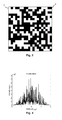
- Fig. 1 shows an SLM 1 with a data pattern consisting of a plurality of pixels 2.
- "off-pixels” are symbolized by black pixels, whereas "on-pixels” are symbolized by white pixels.
- For page oriented data storage usually a 2-dimensional modulation scheme is applied.
- a common approach is to divide each data page 1 into a set of sub pages or blocks consisting, for example, of 4 ⁇ 4 or 5 ⁇ 5 pixels 2.
- the user data is transformed into a set of blocks.
- a known modulation uses three on-pixels in each 4 ⁇ 4 SLM block (4 ⁇ 4-3 modulation).
- the number of combinations of three on-pixels in a 4 ⁇ 4 SLM pixel block is equal to the selection of 3 out of 16, i.e. the number of combinations equals 560. This corresponds to a capacity of ⁇ 9.1 bits of user data per pixel block.
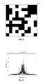
- Fig. 2 shows the intensity distribution in the Fourier plane resulting from the distribution of pixels 2 of the data page 1 of Fig. 1 . Illustrated is a cut through the 2-dimensional distribution in logarithmic scale. As can be seen, the Fourier transform has a high central intensity peak. This DC-peak of the object beam is likely to cause an undesired saturation of the photosensitive medium.
- a phase mask 3 having a plurality of phase cells 4, which introduce a phase shift of 0 or ⁇ for each pixel 2.
- the spatial distribution of the phase shift of 0 or ⁇ is random.
- the size of the phase cells 4 of the phase mask 3 is the same as the size of the pixels 2 of the SLM 1.
- the size of the phase cells 4 is adapted accordingly. In other words, a single phase cell 4 is assigned to each pixel 2.
- Fig. 4 illustrates the intensity distribution in the Fourier plane resulting from the distribution of pixels 2 of the data page 1 of Fig. 1 modulated with the phase mask 3 of Fig 3 . Shown is a cut through the 2-dimensional distribution in linear scale. The phase mask with a cell size of one SLM pixel suppresses the DC-peak quite well. However, a large fraction of intensity is still located above the Nyquist limit. In addition, the intensity distribution within the central region of the Fourier plane is not flat.
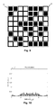
- Fig. 5 shows a phase mask 3 having a cell size two times larger than the SLM pixel size. This means that a single phase cell 4 is assigned to four pixels 2 of the SLM 1. Again, the phase cells 4 introduce a phase shift of 0 or ⁇ for each pixel. The spatial distribution of the phase shift of 0 or ⁇ is random.
- Fig. 6 depicts the intensity distribution in the Fourier plane resulting from the distribution of pixels 2 of the data page 1 of Fig. 1 modulated with the phase mask 3 of Fig 5 . Shown is a cut through the 2-dimensional distribution in linear scale.
- the phase mask 3 reduces the intensity above the Nyquist limit, i.e. outside the interval [-1, 1], whereas the intensity below the Nyquist limit is increased.
- phase mask 3 A first embodiment of a phase mask 3 according to the invention is illustrated in Fig. 7 .
- Each phase cell causes a phase shift of 0 or ⁇ , i.e. the phase mask 3 is binary. However, the phase shift varies within each phase cell 4. Inside a circular area of each phase cell 4 the phase shift is different from the phase shift in the surrounding area. If the phase shift within the circular area is ⁇ , the phase shift in the surrounding area is 0, and vice versa.
- the phase mask 3 is still binary.
- the invention can likewise be realized with a multilevel phase mask.
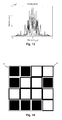
- Fig. 8 depicts the intensity distribution in the Fourier plane resulting from the distribution of pixels 2 of the data page 1 of Fig. 1 modulated with the phase mask 3 of Fig 7 . Shown is a cut through the 2-dimensional distribution in linear scale. As can be seen, the resulting intensity distribution has a flatter envelope.
- FIG. 9 A second embodiment of a phase mask 3 according to the invention is illustrated in Fig. 9 .
- a square-shaped pattern is used instead of the circular pattern of Fig. 7 .
- Fig. 10 The intensity distribution in the Fourier plane resulting from the distribution of pixels 2 of the data page 1 of Fig. 1 modulated with the phase mask 3 of Fig 9 is depicted in Fig. 10 . Shown is a cut through the 2-dimensional distribution in linear scale. The resulting intensity distribution has an even flatter envelope.
- FIG. 11 A third embodiment of a phase mask 3 according to the invention is illustrated in Fig. 11 .
- the sub-cell phase variation of Fig. 7 using a circular-shaped pattern is combined with the low-resolution phase mask 3 depicted in Fig. 5 .
- Fig. 12 The intensity distribution in the Fourier plane resulting from the distribution of pixels 2 of the data page 1 of Fig. 1 modulated with the phase mask 3 of Fig 11 is depicted in Fig. 12 . Shown is a cut through the 2-dimensional distribution in linear scale. The intensity distribution is concentrated below the Nyquist limit and at the same time has a flat envelope.
- FIG. 13 depicts the corresponding intensity distribution in the Fourier plane without the sub-cell phase variation.
- the intensity distribution is still concentrated below the Nyquist limit, but the envelope is no longer flat.
- Fig. 14 shows a fourth embodiment of a phase mask 3 according to the invention.
- the sub-cell phase variation of Fig. 9 using a square-shaped pattern is combined with the low-resolution phase mask 3 depicted in Fig. 5 .
- Fig. 15 The intensity distribution in the Fourier plane resulting from the distribution of pixels 2 of the data page 1 of Fig. 1 modulated with the phase mask 3 of Fig 14 is depicted in Fig. 15 . Shown is a cut through the 2-dimensional distribution in linear scale. Again the intensity distribution is concentrated below the Nyquist limit. At the same time the envelope is even flatter.
- FIG. 16 an apparatus 7 for reading from and/or writing to a holographic storage medium 16 is shown schematically.
- a source of coherent light e.g. a laser diode 8 emits a light beam 9, which is collimated by a collimating lens 10.
- the light beam 9 is then divided into two separate light beams 13, 14, i.e. the object beam 13 and the reference beam 14.
- the division of the light beam 9 is achieved using a first beam splitter 11.
- a spatial light modulator (SLM) 1 modulates the object beam 13 to imprint a 2-dimensional data pattern.
- a phase mask 3 Located behind the SLM 1 is a phase mask 3, which adds a sub-cell scale phase variation to the data pixels of the data pattern.
- phase mask (not shown) can likewise be included in the reference beam path.
- Both the object beam 13 and the reference beam 14 are focused into a holographic storage medium 16, e.g. a holographic disk or card, by an objective lens 15. At the intersection of the object beam 13 and the reference beam 14 an interference pattern appears, which is recorded in a photo-sensitive layer of the holographic storage medium 16.
- the stored data are retrieved from the holographic storage medium 16 by illuminating a recorded hologram with the reference beam 14 only.
- the reference beam 14 is diffracted by the hologram structure and produces a copy of the original object beam 13, the reconstructed object beam 17.
- This reconstructed object beam 17 is collimated by the objective lens 9 and directed onto a 2-dimensional array detector 19, e.g. a CCD-array, by a second beam splitter 18.
- the array detector 19 allows to reconstruct the recorded data.
Priority Applications (7)
| Application Number | Priority Date | Filing Date | Title |
|---|---|---|---|
| EP07114691A EP2028653A1 (fr) | 2007-08-21 | 2007-08-21 | Masque de phase pour stockage de données holographiques |
| US12/218,002 US7990594B2 (en) | 2007-08-21 | 2008-07-10 | Phase mask for holographic data storage |
| KR1020080071126A KR20090019687A (ko) | 2007-08-21 | 2008-07-22 | 홀로그래픽 데이터 스토리지를 위한 위상 마스크 |
| EP08305445A EP2028655B1 (fr) | 2007-08-21 | 2008-08-04 | Appareil et procédé de stockage de données holographiques avec masque de phase |
| DE602008006314T DE602008006314D1 (de) | 2007-08-21 | 2008-08-04 | Vorrichtung und Verfahren zur holographischen Datenspeicherung mit einer Phasenmaske |
| CN200810214211XA CN101373371B (zh) | 2007-08-21 | 2008-08-21 | 全息数据存储的相位掩模 |
| JP2008213176A JP5085467B2 (ja) | 2007-08-21 | 2008-08-21 | ホログラフィデータ記憶用の位相マスク |
Applications Claiming Priority (1)
| Application Number | Priority Date | Filing Date | Title |
|---|---|---|---|
| EP07114691A EP2028653A1 (fr) | 2007-08-21 | 2007-08-21 | Masque de phase pour stockage de données holographiques |
Publications (1)
| Publication Number | Publication Date |
|---|---|
| EP2028653A1 true EP2028653A1 (fr) | 2009-02-25 |
Family
ID=38779737
Family Applications (2)
| Application Number | Title | Priority Date | Filing Date |
|---|---|---|---|
| EP07114691A Withdrawn EP2028653A1 (fr) | 2007-08-21 | 2007-08-21 | Masque de phase pour stockage de données holographiques |
| EP08305445A Expired - Fee Related EP2028655B1 (fr) | 2007-08-21 | 2008-08-04 | Appareil et procédé de stockage de données holographiques avec masque de phase |
Family Applications After (1)
| Application Number | Title | Priority Date | Filing Date |
|---|---|---|---|
| EP08305445A Expired - Fee Related EP2028655B1 (fr) | 2007-08-21 | 2008-08-04 | Appareil et procédé de stockage de données holographiques avec masque de phase |
Country Status (6)
| Country | Link |
|---|---|
| US (1) | US7990594B2 (fr) |
| EP (2) | EP2028653A1 (fr) |
| JP (1) | JP5085467B2 (fr) |
| KR (1) | KR20090019687A (fr) |
| CN (1) | CN101373371B (fr) |
| DE (1) | DE602008006314D1 (fr) |
Cited By (3)
| Publication number | Priority date | Publication date | Assignee | Title |
|---|---|---|---|---|
| EP2267703A1 (fr) | 2009-06-11 | 2010-12-29 | Thomson Licensing | Masque de phase pour système de stockage holographique |
| WO2011018360A1 (fr) | 2009-08-14 | 2011-02-17 | Thomson Licensing | Compensation d'inclinaison pour un système de stockage holographique |
| WO2011018359A1 (fr) | 2009-08-14 | 2011-02-17 | Thomson Licensing | Calibrage de position d'un support de stockage holographique |
Families Citing this family (10)
| Publication number | Priority date | Publication date | Assignee | Title |
|---|---|---|---|---|
| EP2028653A1 (fr) * | 2007-08-21 | 2009-02-25 | Deutsche Thomson OHG | Masque de phase pour stockage de données holographiques |
| TW201006247A (en) * | 2008-07-17 | 2010-02-01 | Ind Tech Res Inst | Holographic data storing method and storing device |
| JP2012220690A (ja) * | 2011-04-07 | 2012-11-12 | Tdk Corp | ホログラフィック記録媒体の記録露光量決定方法及び記録方法 |
| JP6143052B2 (ja) * | 2012-10-22 | 2017-06-07 | 国立研究開発法人産業技術総合研究所 | フーリエ変換ホログラム用ランダム位相マスク |
| KR102026738B1 (ko) | 2013-02-15 | 2019-09-30 | 삼성전자주식회사 | 광변조기 및 이를 이용한 광의 각도 조절 방법 |
| US20160284374A1 (en) * | 2013-11-08 | 2016-09-29 | Hitachi, Ltd. | Holographic storage device |
| CN110060707B (zh) * | 2018-01-18 | 2020-09-01 | 青岛泰谷光电工程技术有限公司 | 一种光学讯号的编码方法和存取方法以及全像储存装置 |
| CN110501892B (zh) * | 2019-07-23 | 2020-08-25 | 中国科学技术大学 | 手性多瓣微结构的制备方法和装置 |
| CN111883185B (zh) * | 2020-06-02 | 2021-06-25 | 华中科技大学 | 一种投影式超分辨光学数据的写入/读出方法及装置 |
| CN112865317A (zh) * | 2021-01-28 | 2021-05-28 | 深圳供电局有限公司 | 智慧电站远程虚拟控制方法、装置及系统 |
Citations (5)
| Publication number | Priority date | Publication date | Assignee | Title |
|---|---|---|---|---|
| US3829193A (en) * | 1972-09-18 | 1974-08-13 | Hitachi Ltd | Improved random phase plate for fourier transform holography |
| US5317435A (en) * | 1990-04-06 | 1994-05-31 | Matsushita Electric Industrial Co., Ltd. | Holographic recording apparatus having a liquid crystal modulator including a diffuser with plural phase shift regions |
| WO1997032243A1 (fr) * | 1996-02-28 | 1997-09-04 | Hagberg, Mats | Dispositif optique pour le traitement d'une onde optique |
| US6281993B1 (en) * | 1998-03-30 | 2001-08-28 | International Business Machines Corporation | Phase shifting element for optical information processing storing systems |
| US20070133113A1 (en) * | 2005-12-12 | 2007-06-14 | Fuji Xerox Co., Ltd. | Hologram recording method and hologram recording device |
Family Cites Families (8)
| Publication number | Priority date | Publication date | Assignee | Title |
|---|---|---|---|---|
| JPS5175452A (ja) * | 1974-12-25 | 1976-06-30 | Tokyo Shibaura Electric Co | Randamuisoban |
| JPS5485737A (en) * | 1977-12-20 | 1979-07-07 | Matsushita Electric Ind Co Ltd | Diffusion plate device |
| JP2000098862A (ja) * | 1998-09-25 | 2000-04-07 | Fuji Xerox Co Ltd | 光記録方法および光記録装置 |
| US7088482B2 (en) * | 2004-02-10 | 2006-08-08 | Imation Corp. | Holographic recording techniques using first and second portions of a spatial light modulator |
| JP2006276373A (ja) * | 2005-03-29 | 2006-10-12 | Sony Corp | ホログラム記録装置及び位相マスク |
| TW200801865A (en) * | 2006-03-29 | 2008-01-01 | Koninkl Philips Electronics Nv | Setup for storing data in a holographic storage medium and phase plate |
| KR100727780B1 (ko) * | 2006-04-06 | 2007-06-14 | 주식회사 대우일렉트로닉스 | 위상 마스크를 구비하는 광 정보 처리 장치 |
| EP2028653A1 (fr) * | 2007-08-21 | 2009-02-25 | Deutsche Thomson OHG | Masque de phase pour stockage de données holographiques |
-
2007
- 2007-08-21 EP EP07114691A patent/EP2028653A1/fr not_active Withdrawn
-
2008
- 2008-07-10 US US12/218,002 patent/US7990594B2/en not_active Expired - Fee Related
- 2008-07-22 KR KR1020080071126A patent/KR20090019687A/ko not_active Application Discontinuation
- 2008-08-04 DE DE602008006314T patent/DE602008006314D1/de active Active
- 2008-08-04 EP EP08305445A patent/EP2028655B1/fr not_active Expired - Fee Related
- 2008-08-21 CN CN200810214211XA patent/CN101373371B/zh not_active Expired - Fee Related
- 2008-08-21 JP JP2008213176A patent/JP5085467B2/ja not_active Expired - Fee Related
Patent Citations (5)
| Publication number | Priority date | Publication date | Assignee | Title |
|---|---|---|---|---|
| US3829193A (en) * | 1972-09-18 | 1974-08-13 | Hitachi Ltd | Improved random phase plate for fourier transform holography |
| US5317435A (en) * | 1990-04-06 | 1994-05-31 | Matsushita Electric Industrial Co., Ltd. | Holographic recording apparatus having a liquid crystal modulator including a diffuser with plural phase shift regions |
| WO1997032243A1 (fr) * | 1996-02-28 | 1997-09-04 | Hagberg, Mats | Dispositif optique pour le traitement d'une onde optique |
| US6281993B1 (en) * | 1998-03-30 | 2001-08-28 | International Business Machines Corporation | Phase shifting element for optical information processing storing systems |
| US20070133113A1 (en) * | 2005-12-12 | 2007-06-14 | Fuji Xerox Co., Ltd. | Hologram recording method and hologram recording device |
Non-Patent Citations (2)
| Title |
|---|
| APPLIED OPTICS USA, vol. 19, no. 2, 15 January 1980 (1980-01-15), pages 215 - 221, ISSN: 0003-6935 * |
| DATABASE INSPEC [online] THE INSTITUTION OF ELECTRICAL ENGINEERS, STEVENAGE, GB; 15 January 1980 (1980-01-15), IWAMOTO A: "Artificial diffuser for Fourier transform hologram recording", XP002461933, Database accession no. 1511793 * |
Cited By (4)
| Publication number | Priority date | Publication date | Assignee | Title |
|---|---|---|---|---|
| EP2267703A1 (fr) | 2009-06-11 | 2010-12-29 | Thomson Licensing | Masque de phase pour système de stockage holographique |
| WO2011018360A1 (fr) | 2009-08-14 | 2011-02-17 | Thomson Licensing | Compensation d'inclinaison pour un système de stockage holographique |
| WO2011018359A1 (fr) | 2009-08-14 | 2011-02-17 | Thomson Licensing | Calibrage de position d'un support de stockage holographique |
| EP2290474A1 (fr) * | 2009-08-14 | 2011-03-02 | Thomson Licensing | Compensation d'inclinaison pour système de stockage holographique |
Also Published As
| Publication number | Publication date |
|---|---|
| KR20090019687A (ko) | 2009-02-25 |
| CN101373371A (zh) | 2009-02-25 |
| EP2028655B1 (fr) | 2011-04-20 |
| DE602008006314D1 (de) | 2011-06-01 |
| US20090051990A1 (en) | 2009-02-26 |
| CN101373371B (zh) | 2013-06-12 |
| JP2009048761A (ja) | 2009-03-05 |
| US7990594B2 (en) | 2011-08-02 |
| EP2028655A1 (fr) | 2009-02-25 |
| JP5085467B2 (ja) | 2012-11-28 |
Similar Documents
| Publication | Publication Date | Title |
|---|---|---|
| US7990594B2 (en) | Phase mask for holographic data storage | |
| US8179767B2 (en) | Data page for use in a holographic data storage system | |
| JP5190980B2 (ja) | コモンパス干渉計に基づくホログラフィック・ストレージ・システム | |
| US8284469B2 (en) | Apparatus for reading from and/or writing to holographic storage media | |
| US7965430B2 (en) | Pre-exposure and curing of photo-sensitive material for optical data storage | |
| EP1775723A1 (fr) | Support de stockage de données holographiques | |
| US8116185B2 (en) | Holographic storage medium with integrated phase mask | |
| EP1837871B1 (fr) | Système et méthode de stockage de données holographique | |
| EP1933311B1 (fr) | Pré-exposition et séchage de matériau photosensible pour stockage de données optiques | |
| EP1873766B1 (fr) | Système de stockage holographique basé sur l'interférométrie de chemin commun | |
| CN101727931A (zh) | 具有改善的数据分页质量的全息存储系统 |
Legal Events
| Date | Code | Title | Description |
|---|---|---|---|
| PUAI | Public reference made under article 153(3) epc to a published international application that has entered the european phase |
Free format text: ORIGINAL CODE: 0009012 |
|
| AK | Designated contracting states |
Kind code of ref document: A1 Designated state(s): AT BE BG CH CY CZ DE DK EE ES FI FR GB GR HU IE IS IT LI LT LU LV MC MT NL PL PT RO SE SI SK TR |
|
| AX | Request for extension of the european patent |
Extension state: AL BA HR MK RS |
|
| AKX | Designation fees paid | ||
| STAA | Information on the status of an ep patent application or granted ep patent |
Free format text: STATUS: THE APPLICATION IS DEEMED TO BE WITHDRAWN |
|
| 18D | Application deemed to be withdrawn |
Effective date: 20090826 |
|
| REG | Reference to a national code |
Ref country code: DE Ref legal event code: 8566 |