EP2028421A1 - Surveillance de la présence d'une flamme et de la température de la flamme - Google Patents
Surveillance de la présence d'une flamme et de la température de la flamme Download PDFInfo
- Publication number
- EP2028421A1 EP2028421A1 EP07016386A EP07016386A EP2028421A1 EP 2028421 A1 EP2028421 A1 EP 2028421A1 EP 07016386 A EP07016386 A EP 07016386A EP 07016386 A EP07016386 A EP 07016386A EP 2028421 A1 EP2028421 A1 EP 2028421A1
- Authority
- EP
- European Patent Office
- Prior art keywords
- sensor
- burner
- flame
- radiation
- outer side
- Prior art date
- Legal status (The legal status is an assumption and is not a legal conclusion. Google has not performed a legal analysis and makes no representation as to the accuracy of the status listed.)
- Withdrawn
Links
- 238000012544 monitoring process Methods 0.000 title claims abstract description 13
- 238000002485 combustion reaction Methods 0.000 claims abstract description 73
- 230000005855 radiation Effects 0.000 claims abstract description 36
- 238000000034 method Methods 0.000 claims abstract description 13
- 239000007789 gas Substances 0.000 claims description 20
- 230000003287 optical effect Effects 0.000 claims description 9
- 239000011261 inert gas Substances 0.000 claims description 6
- 239000000203 mixture Substances 0.000 description 8
- 239000000446 fuel Substances 0.000 description 7
- 239000000463 material Substances 0.000 description 6
- 238000005259 measurement Methods 0.000 description 6
- 238000012546 transfer Methods 0.000 description 6
- IJGRMHOSHXDMSA-UHFFFAOYSA-N Atomic nitrogen Chemical compound N#N IJGRMHOSHXDMSA-UHFFFAOYSA-N 0.000 description 3
- 230000005670 electromagnetic radiation Effects 0.000 description 3
- 230000035945 sensitivity Effects 0.000 description 3
- 230000005457 Black-body radiation Effects 0.000 description 2
- 238000006243 chemical reaction Methods 0.000 description 2
- 230000001419 dependent effect Effects 0.000 description 2
- 238000013461 design Methods 0.000 description 2
- 230000003647 oxidation Effects 0.000 description 2
- 238000007254 oxidation reaction Methods 0.000 description 2
- 230000007704 transition Effects 0.000 description 2
- 238000009529 body temperature measurement Methods 0.000 description 1
- 230000001010 compromised effect Effects 0.000 description 1
- 238000001514 detection method Methods 0.000 description 1
- 238000011161 development Methods 0.000 description 1
- 230000018109 developmental process Effects 0.000 description 1
- 229910001873 dinitrogen Inorganic materials 0.000 description 1
- 239000007788 liquid Substances 0.000 description 1
- 229910052757 nitrogen Inorganic materials 0.000 description 1
- 238000005476 soldering Methods 0.000 description 1
- 238000005406 washing Methods 0.000 description 1
- XLYOFNOQVPJJNP-UHFFFAOYSA-N water Substances O XLYOFNOQVPJJNP-UHFFFAOYSA-N 0.000 description 1
- 238000003466 welding Methods 0.000 description 1
Images


Classifications
-
- F—MECHANICAL ENGINEERING; LIGHTING; HEATING; WEAPONS; BLASTING
- F23—COMBUSTION APPARATUS; COMBUSTION PROCESSES
- F23N—REGULATING OR CONTROLLING COMBUSTION
- F23N5/00—Systems for controlling combustion
- F23N5/02—Systems for controlling combustion using devices responsive to thermal changes or to thermal expansion of a medium
- F23N5/08—Systems for controlling combustion using devices responsive to thermal changes or to thermal expansion of a medium using light-sensitive elements
- F23N5/082—Systems for controlling combustion using devices responsive to thermal changes or to thermal expansion of a medium using light-sensitive elements using electronic means
-
- F—MECHANICAL ENGINEERING; LIGHTING; HEATING; WEAPONS; BLASTING
- F02—COMBUSTION ENGINES; HOT-GAS OR COMBUSTION-PRODUCT ENGINE PLANTS
- F02B—INTERNAL-COMBUSTION PISTON ENGINES; COMBUSTION ENGINES IN GENERAL
- F02B77/00—Component parts, details or accessories, not otherwise provided for
- F02B77/08—Safety, indicating, or supervising devices
- F02B77/085—Safety, indicating, or supervising devices with sensors measuring combustion processes, e.g. knocking, pressure, ionization, combustion flame
-
- F—MECHANICAL ENGINEERING; LIGHTING; HEATING; WEAPONS; BLASTING
- F02—COMBUSTION ENGINES; HOT-GAS OR COMBUSTION-PRODUCT ENGINE PLANTS
- F02B—INTERNAL-COMBUSTION PISTON ENGINES; COMBUSTION ENGINES IN GENERAL
- F02B77/00—Component parts, details or accessories, not otherwise provided for
- F02B77/08—Safety, indicating, or supervising devices
- F02B77/089—Safety, indicating, or supervising devices relating to engine temperature
-
- F—MECHANICAL ENGINEERING; LIGHTING; HEATING; WEAPONS; BLASTING
- F02—COMBUSTION ENGINES; HOT-GAS OR COMBUSTION-PRODUCT ENGINE PLANTS
- F02D—CONTROLLING COMBUSTION ENGINES
- F02D35/00—Controlling engines, dependent on conditions exterior or interior to engines, not otherwise provided for
- F02D35/02—Controlling engines, dependent on conditions exterior or interior to engines, not otherwise provided for on interior conditions
- F02D35/022—Controlling engines, dependent on conditions exterior or interior to engines, not otherwise provided for on interior conditions using an optical sensor, e.g. in-cylinder light probe
-
- F—MECHANICAL ENGINEERING; LIGHTING; HEATING; WEAPONS; BLASTING
- F23—COMBUSTION APPARATUS; COMBUSTION PROCESSES
- F23D—BURNERS
- F23D2208/00—Control devices associated with burners
- F23D2208/10—Sensing devices
-
- F—MECHANICAL ENGINEERING; LIGHTING; HEATING; WEAPONS; BLASTING
- F23—COMBUSTION APPARATUS; COMBUSTION PROCESSES
- F23N—REGULATING OR CONTROLLING COMBUSTION
- F23N2229/00—Flame sensors
-
- F—MECHANICAL ENGINEERING; LIGHTING; HEATING; WEAPONS; BLASTING
- F23—COMBUSTION APPARATUS; COMBUSTION PROCESSES
- F23N—REGULATING OR CONTROLLING COMBUSTION
- F23N2900/00—Special features of, or arrangements for controlling combustion
- F23N2900/05005—Mounting arrangements for sensing, detecting or measuring devices
Definitions
- the present invention relates to a device and a method for monitoring a flame in a combustion chamber. Especially, it relates to a temperature measurement arrangement for use in a burner of a gas turbine engine.
- a gas turbine engine usually comprises a compressor, a combustion chamber and a turbine.
- the compressor delivers compressed air for use in the combustion chamber.
- a mixture of air and fuel is combusted by means of a burner in order to produce a hot gas stream which drives the turbine.
- a burner typically one or more burners are used.
- the heat release rate is an indication of the intensity of the chemical reaction and the stability of the flame.
- the first objective is solved by a method for monitoring a flame in a combustion chamber as claimed in claim 1.
- the second objective is solved by a burner as claimed in claim 6 and the third objective is solved by a gas turbine as claimed in claim 14.
- the still further objective is solved by an internal combustion engine as claimed in claim 15.
- the depending claims define further developments of the invention.
- the inventive method for monitoring a flame relates to a combustion chamber which comprises a wall with an inner side and an outer side. While the inner side shows towards the flame in the interior of the combustion chamber, the outer side shows away from the interior and the flame.
- the method is characterised in that the radiation which is emitted from a part of the outer side of the wall is optically detected by a sensor.
- the wall of the combustion chamber is heated up depending on the existence and the temperature of a flame inside the combustion chamber. Due to the increased temperature the wall, or especially a particular part of the wall, emits radiation which generally can be detected optically.
- This is used by the inventive method, wherein the black body radiation from the surface of the combustion chamber is detected based on an optical measurement.
- This method has the advantage that it is unaffected by rapid changes in temperature. Comparable devices using thermocouples would be likely to fail due to their fragility.
- the heat release rate and/or the temperature of the part of the outer side of the wall can be determined by means of the detected radiation.
- the temperature of the wall provides information regarding the existence and the intensity of the heat release rate from the flame inside the combustion chamber.
- the heat release rate is an indication of the intensity of the chemical reaction and the stability of the flame.
- the mentioned wall of the combustion chamber may be the actual wall of the combustion chamber. However, it may as well be a wall section of a device attached to the combustion chamber such as, for example, a wall section of a burner. In this case the outer side of a wall section of the burner is to be regarded as a part of the outer side of the combustion chamber in the context of this invention.
- the used sensor may, for instance, be a photodiode.
- the detected radiation can be focussed on the sensor.
- the detected radiation may be focussed by means of an optical lens. A focussing of the emitted radiation reduces the influence of radiation which is not emitted from the desired part of the outer side of the wall of the combustion chamber. This further increases the accuracy of the measurement.
- the emitted radiation can be detected from the part of the outer side of the wall which is situated opposite a part of the inner side of the wall which is exposed to the flame.
- the flame directly heats up the inner side of the wall and the heat is transported through the wall to the outer side of the wall by thermal conduction.
- the temperature of the outer side of the wall is directly related to the characteristics of the flame inside the combustion chamber.
- the black body radiation from the outer side of the wall due to the increased temperature can be detected and can be used to determine the temperature of the outer side of the wall. Hence, also temperature of the flame inside the combustion chamber can be determined.
- the emitted radiation can be detected from the bottom of a hole in the wall which extends from the outer side of the wall towards the inner side of the wall.
- the thickness of the wall which is the distance between the inner and the outer side of the wall, is smaller than at other parts of the wall. This provides very effective and fast heat conduction between the inner and the other side of the wall.
- the inventive burner which is suitable for monitoring the flame in the combustion zone of a combustion chamber, comprises a wall section with an inner side which shows towards a combustion zone, and an outer side which shows away from the combustion zone. It further comprises a sensor for optically detecting the radiation emitted from the outer side of said wall section.
- a sensor for optically detecting the radiation emitted from the outer side of said wall section.
- the used sensor is a photodiode.
- the burner may further comprise an element to focus the emitted radiation to the sensor. This element may be, for instance, an optical lens. A focussing of the emitted radiation increases the accuracy and sensitivity of the measurement. Furthermore, it reduces the influence of radiation which is not emitted from the outer side of said wall section of the burner.
- said wall section forms the bottom of a hole extending from the outer side towards the inner side.
- the sensor can then be positioned such that it detects the radiation emitted from the bottom of said hole.
- the sensor may be located at a distance of the bottom of the hole.
- the hole can be evacuated or filled with an inert gas. For instance nitrogen gas may be used.
- An evacuated or inert gas filled hole protects the sensor, especially the surface of the sensor. Furthermore, it reduces the oxidation of the surface of the bottom of the hole.
- the senor can be positioned in the burner such that it can detect the radiation emitted from the outer side of a part of the wall, the corresponding inner side of which is exposed to the flame.
- the detected radiation provides nearly direct information about the temperature of the flame itself.
- the hole and the sensor can especially be positioned in the burner such that it detects the radiation emitted from the outer side of a part of the wall, the corresponding inner side of which is located near the base of the flame.
- the base of the flame is defined by the location of the attachment of a low pressure region generated by a swirling mix of air and fuel. The detection of the radiation emitted from a region located near the base of the flame provides information about the characteristics of the flame.
- the burner may further comprise a light emitting diode to determine the state of the sensor.
- a light emitting diode to determine the state of the sensor.
- the state of the photodiode can be auto checked by fitting a light emitting diode to a part of the photodiode's surface.
- the photodiode's response to the light emitting diode determines the state of the sensor prior to the starting of the machine fitted with this sensor.
- the inventive gas turbine comprises an inventive burner, as previously described. It also has the mentioned advantages.
- an internal combustion engine comprising at least one cylinder with a wall section having an inner side which shows towards a combustion zone, and an outer side which shows away from the combustion zone.
- the internal combustion engine further comprises a sensor for optically detecting the radiation emitted from the outer side of said wall section.
- the design of said wall section and the sensor can be the same as in the inventive burner.
- the inventive internal combustion engine allows for monitoring the cylinder(s) over a period of time, thereby enabling the monitoring of the average flame temperature or average fuel/air mix etc. This is most suitable for diesel engines at fixed revolutions per minute for periods of time.
- Figure 1 schematically shows a part of a combustor of a gas turbine engine in a sectional view.
- the combustor comprises in flow series a burner with a swirler portion 3 and a burner-head portion 11 attached to the swirler portion 3, a transition piece being referred as combustion pre-chamber 5 and a main combustion chamber 9.
- the main combustion chamber 9 has a diameter being larger than the diameter of the pre-chamber 5.
- the main combustion chamber 9 is connected to the pre-chamber 5 via a dome portion 30.
- the transition piece 5 may be implemented as a one part continuation of the burner towards the main combustion chamber 9, as a one part continuation of the main combustion chamber 9 towards the burner, or as a separate part between the burner and the main combustion chamber 9.
- the burner comprises a radial swirler 3 and a head plate 11 to which the swirler 3 is fixed.
- the head plate 11 is fixed to an outer casing 10 of the combustor.
- the burner-head plate 11 comprises a removable assembly 13 which is situated in the middle of the burner-head plate 11, as indicated by the centre line 27.
- the radial swirler 3, the pre-chamber 5 and the main combustion chamber 9 show radial symmetry about a centre axis or centre line 27.
- a flow channel 28 for feeding compressor air into the burner is situated between the outer casing 10 and the radial swirler 3, the pre-chamber 5 and the main combustion chamber 9.
- Compressed air 24 flows in the direction of the arrows 1 through the flow channel 28 towards the burner-head plate 11.
- the compressed air 24 turns about 90° so as to enter the radial swirler 3, as indicated by arrows 2.
- the swirler 3 comprises a plurality of vanes which are arranged in a circle and flow slots being defined between adjacent vanes in the circle.
- the compressed air flows through the slots into the pre-chamber 5, as indicated by arrows 4.
- Fuel is introduced into the air flowing through the slots by fuel nozzles located in the vanes.
- the swirler 3 therefore provides a swirling mixture of air and fuel.
- the slots are inclined with respect to the combustor's radial direction so that a swirl is generated in the fuel-air-mixture 6 when entering the pre-chamber 5.
- the compressed air generally flows in the direction indicated by arrows 6, thereby forming the swirling air-fuel-mixture 6.
- the air-fuel-mixture 6 flows in the direction as indicated by arrows 8 through the pre-chamber 5 into the main combustion chamber 9 where it combusts.
- FIG 2 schematically shows the location of the flame in the described combustor in a sectional view.
- the burner-head plate 11 comprises a removable assembly 13.
- the combusting mixture of air and fuel forms a flame which follows the region of low pressure 12.
- the base of the low pressure region 12, which defines the base of the flame 23, is attached to the inner side 21 of the removable assembly 13.
- the removable assembly 13 is schematically shown in a sectional view.
- the removable assembly 13 comprises a plug 25 and a cover plate 26, which is connected to the plug 25.
- the plug 25 is an element which fits into a central hole in the burner-head plate 11 and the cover plate 26 is used to fix the removable assembly 13 to the burner-head plate 11.
- the removable assembly 13 further comprises a blind hole 18 which is located in the centre of the removable assembly 13 along the centre line 27.
- the blind hole 18 may be positioned in the removable assembly parallel to the centre line 27, but not in the centre of the removable assembly 13.
- the blind hole 18 extends through the cover plate 26 and through a major part of the plug 25.
- the bottom 17 of the blind hole 18 has a relatively small distance 22 to the inner surface 21 of the removable assembly 13. While the inner surface 21 shows towards the flame, i.e. towards the interior of the combustion chamber, the surface of the bottom 17 of the hole 18 shows away from the interior of the combustion chamber and can thus be regarded as an outer surface of the burner as seen from the interior of the combustion chamber.
- the bottom 17 of the hole 18 forms a wall section with inner side 21 which shows towards a combustion zone, and an outer side which shows away from the combustion zone.
- the removable assembly 13 comprises a pipe fitting 14, a tube extension piece 15 and an embedded photodiode 16.
- the pipe fitting 14 is connected to the cover plate 27.
- the pipe fitting 14 connects the removable assembly 13 to the tube extension piece 15 and the embedded photodiode 16.
- a bore 31 extends entirely though the pipe fitting 14 and the extension piece 15 and is aligned with the blind hole 18.
- the photodiode 16 is fixed to the end of the tube extension piece 15 and closes the bore 31.
- the hole 18 is concentric to the bore of the pipe fitting 14, such as a Swagelock fitting.
- the length of the blind hole 18, the pipe fitting 14 and the tube extension piece 15 are such as to provide a collimated viewing angle from the photodiode's sensor to the bottom of the blind hole 17.
- the blind hole 18 is formed in the removable assembly 13 with a flat bottom face 17.
- the hole 18 may be reamed flat to a distance 22 to the inner surface 21 of the removable assembly.
- the distance 22 is specified by the material properties of the assembly 13 in such a way as to provide an optimal heat transfer from the inner surface 21 of the removable assembly 13 to the bottom 17 of the hole 18.
- the inner surface 21 is exposed to the base of a flame 23. This increases the temperature of the inner surface 21 and, through thermal conduction, also the temperature at the surface of the bottom 17 of the blind hole 18 raises. When this occurs the surface of the bottom 17 radiates electromagnetic radiation which the photodiode 16 is sensitive to. Radiation from the surrounding walls of the hole do not interfere substantially with the photodiode 16 since the length of the hole 18, the pipe fitting 14 and the tube extension piece 15 collimates the viewing angle such that the electromagnetic radiation from the bottom of the hole 17 dominates the radiation seen by the photodiode 16.
- optical lens 19 or other focusing means, which may be mounted as indicated by lens 19 in Figure 4.
- Figure 4 schematically shows a respective variant of the removable assembly 13 of Figure 3 in a sectional view.
- the optical lens 19 is mounted inside the bore 31 between the pipe fitting 14 and the tube extension piece 15. In this configuration the lens 19 is located such that the focal point of the lens 19 is located on the surface of the bottom 17 of the blind hole 18.
- the use of a focussing lens increases the accuracy and the sensitivity of the measurement.
- the removable assembly 13 may be additionally equipped with a gas filling port 20, as it is shown in Figure 5.
- Figure 5 schematically shows a respective variant of the removable assembly 13 of Figure 3 in a sectional view.
- the hole 18 is connected to a filling port 20 which is, in the present embodiment, a gas filling port.
- a filling port 20 which is, in the present embodiment, a gas filling port.
- the gas filling port 20 is connected to the tube extension piece 15 since no lens is present. It comprises a flow channel which is connected to the bore 31 and may be used to evacuate the bore 31 and the blind hole 18 or to fill the bore 31 and the blind hole 18 with a gas.
- the filling gas may be an inert gas, for instance nitrogen. This reduces the oxidation of the surface of the bottom 17 of the blind hole 18.
- the blind hole 18 may also be filled with a suitable liquid.
- the flame inside the combustion chamber heats up the inner surface 21 of the removable assembly 13.
- the heat is transferred through the wall and heats up the bottom 17 of the blind hole 18. Due to its increased temperature the bottom 17 emits electromagnetic radiation. This radiation propagates through the hole 18 and is detected by the photodiode 16. The results of this measurement can be used to determine the temperature of the bottom of the hole 17.
- the distance 22 and the heat transfer coefficient of the material of the plug 25 also the temperature of the flame inside the combustion chamber and the heat release rate can be determined.
- the speed of response of the measurement to changes in the flame temperature at the inner surface 21 of the removable assembly 13 is dependent on the heat transfer coefficient of the assembly 13, in particular of the material of the plug 25, and the distance 22.
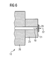
- the heat transfer coefficient and the distance 22 can be adjusted by using a separate bottom plate 29 as wall between the hole 118 and the inner side of the burner.
- the hole is not a blind hole but a through hole 118 which is closed to the interior of the combustion chamber by the bottom plate 29.
- Figure 6 shows a part of the removable assembly 13 in a sectional view. One can see the plug 25 and a part of the cover plate 26.
- the plug 25 and the cover plate 26 comprise the through hole 118.
- the hole 18 is closed by the bottom plate 29.
- the distance 22 is now determined by the thickness of the bottom plate 29.
- the bottom plate 29 is fixed to the plug 25, for instance by welding, soldering or a detachable connection.
- the heat transfer characteristics can be changed just by exchanging the bottom plate for another bottom plate with, for example, a different thickness and/or different material characteristics.
- the use of a separate bottom plate 29 made of a suitable material therefore allows for individual adjustment of the heat transfer coefficient and the distance 22 dependent on the requirements of the particular burner and the used sensor 16. The adjustment is independent of the characteristics of the material of the plug 25.
- an inventive removable assembly can comprise a bottom plate 29, a lens 19 and one or more gas filling ports 20.
- the sensor is a seal unit and as a result the optical system is not compromised by water washing of the machine's compressor.
- Figures 7 to 9 show a cylinder of an internal combustion engine with a removable assembly 213 which allows for monitoring the temperature inside the cylinder. While Figure 7 shows a top view onto the cylinder 200, Figures 8 and 9 show cuts through the cylinder taken in mutually perpendicular directions.
- Figure 8 shows a section through the cylinder 200 in which a cylinder wall 202, the inlet and outlet valves 204, 206, respectively, the spark plug 208 and a piston 210 are partly shown.
- Figure 9 shows a section through the cylinder 200 which is perpendicular to the section shown in Figure 8 . The relation between the two sections is shown in Figure 7 .
- the removable assembly 213 is located in the cylinder head 212 beside the spark plug 208.
- the arrangement of the spark plug 208, the valves 204, 206 and the removable assembly 213 can be best seen in Figure 7 .
- the design of the removable assembly can be the same as has been described with respect to Figures 3 to 6 in conjunction with the gas turbine burner.
- the invention provides the possibility to monitor a flame inside a combustion chamber or a cylinder by optical means.
Landscapes
- Engineering & Computer Science (AREA)
- Chemical & Material Sciences (AREA)
- Combustion & Propulsion (AREA)
- Mechanical Engineering (AREA)
- General Engineering & Computer Science (AREA)
- Control Of Combustion (AREA)
Priority Applications (2)
| Application Number | Priority Date | Filing Date | Title |
|---|---|---|---|
| EP07016386A EP2028421A1 (fr) | 2007-08-21 | 2007-08-21 | Surveillance de la présence d'une flamme et de la température de la flamme |
| US12/229,331 US7765856B2 (en) | 2007-08-21 | 2008-08-21 | Monitoring of a flame existence and a flame temperature |
Applications Claiming Priority (1)
| Application Number | Priority Date | Filing Date | Title |
|---|---|---|---|
| EP07016386A EP2028421A1 (fr) | 2007-08-21 | 2007-08-21 | Surveillance de la présence d'une flamme et de la température de la flamme |
Publications (1)
| Publication Number | Publication Date |
|---|---|
| EP2028421A1 true EP2028421A1 (fr) | 2009-02-25 |
Family
ID=38904631
Family Applications (1)
| Application Number | Title | Priority Date | Filing Date |
|---|---|---|---|
| EP07016386A Withdrawn EP2028421A1 (fr) | 2007-08-21 | 2007-08-21 | Surveillance de la présence d'une flamme et de la température de la flamme |
Country Status (2)
| Country | Link |
|---|---|
| US (1) | US7765856B2 (fr) |
| EP (1) | EP2028421A1 (fr) |
Cited By (1)
| Publication number | Priority date | Publication date | Assignee | Title |
|---|---|---|---|---|
| EP2385233A1 (fr) * | 2010-05-07 | 2011-11-09 | Alstom Technology Ltd | Procédé d'exploitation d'une unité de turbine à gaz basée sur la température de la chambre de combustion |
Families Citing this family (11)
| Publication number | Priority date | Publication date | Assignee | Title |
|---|---|---|---|---|
| US9354618B2 (en) | 2009-05-08 | 2016-05-31 | Gas Turbine Efficiency Sweden Ab | Automated tuning of multiple fuel gas turbine combustion systems |
| US8437941B2 (en) | 2009-05-08 | 2013-05-07 | Gas Turbine Efficiency Sweden Ab | Automated tuning of gas turbine combustion systems |
| US9267443B2 (en) | 2009-05-08 | 2016-02-23 | Gas Turbine Efficiency Sweden Ab | Automated tuning of gas turbine combustion systems |
| US9671797B2 (en) | 2009-05-08 | 2017-06-06 | Gas Turbine Efficiency Sweden Ab | Optimization of gas turbine combustion systems low load performance on simple cycle and heat recovery steam generator applications |
| US20130040254A1 (en) * | 2011-08-08 | 2013-02-14 | General Electric Company | System and method for monitoring a combustor |
| US10392959B2 (en) * | 2012-06-05 | 2019-08-27 | General Electric Company | High temperature flame sensor |
| US9435690B2 (en) * | 2012-06-05 | 2016-09-06 | General Electric Company | Ultra-violet flame detector with high temperature remote sensing element |
| US20140136085A1 (en) * | 2012-11-15 | 2014-05-15 | Ford Global Technologies, Llc | Laser ignition and misfire monitor |
| EP2762687A1 (fr) | 2013-02-01 | 2014-08-06 | Siemens Aktiengesellschaft | Procédé de démarrage d'un système de combustion |
| US9773584B2 (en) | 2014-11-24 | 2017-09-26 | General Electric Company | Triaxial mineral insulated cable in flame sensing applications |
| US10876426B2 (en) * | 2019-04-09 | 2020-12-29 | Pratt & Whitney Canada Corp. | Removable turbine gaspath sensor |
Citations (11)
| Publication number | Priority date | Publication date | Assignee | Title |
|---|---|---|---|---|
| GB1286651A (en) | 1968-09-12 | 1972-08-23 | Shell Int Research | Monitoring device for an internal combustion burner |
| US4422323A (en) | 1981-02-20 | 1983-12-27 | Robert Bosch Gmbh | Combustion process observation element construction |
| EP0448310A1 (fr) * | 1990-03-23 | 1991-09-25 | General Electric Company | Système de détection de flammes pour une turbine à gaz |
| EP0593413A1 (fr) * | 1992-10-16 | 1994-04-20 | AVL Gesellschaft für Verbrennungskraftmaschinen und Messtechnik mbH.Prof.Dr.Dr.h.c. Hans List | Arrangement de mesure optoélectronique |
| US5578828A (en) | 1994-11-15 | 1996-11-26 | General Electric Company | Flame sensor window coating compensation |
| WO1998011388A1 (fr) * | 1996-09-12 | 1998-03-19 | Unison Industries Limited Partnership | Procedes et dispositif de diagnostic pour circuits d'allumage par laser |
| US5777668A (en) * | 1994-08-25 | 1998-07-07 | Amano & Associates Incorporated | Furnace monitoring camera with pivoting zoom lens |
| US20030106536A1 (en) | 2001-11-08 | 2003-06-12 | Heiko Sass | Apparatus and method for indirectly determining a temperature at a predetermined location in an internal combustion engine |
| WO2006067389A1 (fr) | 2004-12-21 | 2006-06-29 | Rolls-Royce Plc | Systeme d’alarme incendie |
| DE102005020328A1 (de) * | 2005-04-30 | 2006-11-09 | Rag Aktiengesellschaft | Temperaturmessung in Verkokungsöfen |
| US20070059655A1 (en) | 2004-02-12 | 2007-03-15 | Alstom Technology Ltd | Premix burner with a swirl generator delimiting a conical swirl space and having sensor monitoring |
Family Cites Families (7)
| Publication number | Priority date | Publication date | Assignee | Title |
|---|---|---|---|---|
| US4995805A (en) * | 1989-02-24 | 1991-02-26 | Gas Research Institute | Method and apparatus for increasing radiant heat production of hydrocarbon fuel combustion systems |
| US5257496A (en) * | 1992-05-05 | 1993-11-02 | General Electric Company | Combustion control for producing low NOx emissions through use of flame spectroscopy |
| DE19628960B4 (de) * | 1996-07-18 | 2005-06-02 | Alstom Technology Ltd | Temperaturmeßvorrichtung |
| US5961314A (en) * | 1997-05-06 | 1999-10-05 | Rosemount Aerospace Inc. | Apparatus for detecting flame conditions in combustion systems |
| US7112796B2 (en) * | 1999-02-08 | 2006-09-26 | General Electric Company | System and method for optical monitoring of a combustion flame |
| US7484369B2 (en) * | 2004-05-07 | 2009-02-03 | Rosemount Aerospace Inc. | Apparatus for observing combustion conditions in a gas turbine engine |
| US7532810B2 (en) * | 2005-09-22 | 2009-05-12 | Sunbeam Products, Inc. | Portable electrical appliance with diagnostic system |
-
2007
- 2007-08-21 EP EP07016386A patent/EP2028421A1/fr not_active Withdrawn
-
2008
- 2008-08-21 US US12/229,331 patent/US7765856B2/en not_active Expired - Fee Related
Patent Citations (11)
| Publication number | Priority date | Publication date | Assignee | Title |
|---|---|---|---|---|
| GB1286651A (en) | 1968-09-12 | 1972-08-23 | Shell Int Research | Monitoring device for an internal combustion burner |
| US4422323A (en) | 1981-02-20 | 1983-12-27 | Robert Bosch Gmbh | Combustion process observation element construction |
| EP0448310A1 (fr) * | 1990-03-23 | 1991-09-25 | General Electric Company | Système de détection de flammes pour une turbine à gaz |
| EP0593413A1 (fr) * | 1992-10-16 | 1994-04-20 | AVL Gesellschaft für Verbrennungskraftmaschinen und Messtechnik mbH.Prof.Dr.Dr.h.c. Hans List | Arrangement de mesure optoélectronique |
| US5777668A (en) * | 1994-08-25 | 1998-07-07 | Amano & Associates Incorporated | Furnace monitoring camera with pivoting zoom lens |
| US5578828A (en) | 1994-11-15 | 1996-11-26 | General Electric Company | Flame sensor window coating compensation |
| WO1998011388A1 (fr) * | 1996-09-12 | 1998-03-19 | Unison Industries Limited Partnership | Procedes et dispositif de diagnostic pour circuits d'allumage par laser |
| US20030106536A1 (en) | 2001-11-08 | 2003-06-12 | Heiko Sass | Apparatus and method for indirectly determining a temperature at a predetermined location in an internal combustion engine |
| US20070059655A1 (en) | 2004-02-12 | 2007-03-15 | Alstom Technology Ltd | Premix burner with a swirl generator delimiting a conical swirl space and having sensor monitoring |
| WO2006067389A1 (fr) | 2004-12-21 | 2006-06-29 | Rolls-Royce Plc | Systeme d’alarme incendie |
| DE102005020328A1 (de) * | 2005-04-30 | 2006-11-09 | Rag Aktiengesellschaft | Temperaturmessung in Verkokungsöfen |
Cited By (1)
| Publication number | Priority date | Publication date | Assignee | Title |
|---|---|---|---|---|
| EP2385233A1 (fr) * | 2010-05-07 | 2011-11-09 | Alstom Technology Ltd | Procédé d'exploitation d'une unité de turbine à gaz basée sur la température de la chambre de combustion |
Also Published As
| Publication number | Publication date |
|---|---|
| US20090049894A1 (en) | 2009-02-26 |
| US7765856B2 (en) | 2010-08-03 |
Similar Documents
| Publication | Publication Date | Title |
|---|---|---|
| US7765856B2 (en) | Monitoring of a flame existence and a flame temperature | |
| JP4112043B2 (ja) | 温度測定装置 | |
| EP2508801B1 (fr) | Système pour observer les conditions de combustion dans une turbine à gaz | |
| EP1764554B1 (fr) | Dispositif pour observer les conditions de combustion dans une turbine à gaz | |
| US7966834B2 (en) | Apparatus for observing combustion conditions in a gas turbine engine | |
| US8371102B1 (en) | Combustor control based on fuel modulation and passive optical sensors | |
| EP2372246A2 (fr) | Microphones à fibres optiques pour un contrôle actif de la combustion | |
| CN209459789U (zh) | 包含热像温度传感器的系统和包含燃气涡轮机引擎的系统 | |
| US5180227A (en) | Optical temperature sensors | |
| EP4105556A1 (fr) | Brûleur doté d'un mécanisme d'allumage par torche et son procédé de fonctionnement | |
| JP2008151512A (ja) | 燃焼式熱量計 | |
| CN110121637B (zh) | 内燃机的发动机部件中的燃烧压力传感器及其组件 | |
| US7618254B2 (en) | Method for igniting a burner | |
| JP2008002279A (ja) | レーザ着火式内燃機関の燃焼制御装置 | |
| EP3674674B1 (fr) | Détecteur de flamme | |
| JP6216935B2 (ja) | ボア変形量測定装置 | |
| JP2008045496A (ja) | 光センサ内蔵レーザ着火装置 | |
| KR20210113241A (ko) | 레이저 유도 백열 원리를 사용하여 유동 유체에서 입자 또는 에어로졸을 검출하는 센서 장치 | |
| KR101505886B1 (ko) | 전자식 공연비 제어장치 | |
| CN107228017B (zh) | 设置有热声不稳定检测的燃气轮机设备和控制其的方法 | |
| JP6635778B2 (ja) | コンロ用バーナ、及びそれを備えたコンロ | |
| JP6317277B2 (ja) | 内燃機関の燃料ガス濃度測定装置 | |
| JPH07208734A (ja) | 火炎検出システム | |
| JP6260296B2 (ja) | バーナおよび熱源機 | |
| JP2006132492A (ja) | レーザ光透過プリズムを備えたレーザ着火式エンジン |
Legal Events
| Date | Code | Title | Description |
|---|---|---|---|
| PUAI | Public reference made under article 153(3) epc to a published international application that has entered the european phase |
Free format text: ORIGINAL CODE: 0009012 |
|
| 17P | Request for examination filed |
Effective date: 20080623 |
|
| AK | Designated contracting states |
Kind code of ref document: A1 Designated state(s): AT BE BG CH CY CZ DE DK EE ES FI FR GB GR HU IE IS IT LI LT LU LV MC MT NL PL PT RO SE SI SK TR |
|
| AX | Request for extension of the european patent |
Extension state: AL BA HR MK RS |
|
| AKX | Designation fees paid |
Designated state(s): DE FR GB IT |
|
| RAP1 | Party data changed (applicant data changed or rights of an application transferred) |
Owner name: SIEMENS AKTIENGESELLSCHAFT |
|
| STAA | Information on the status of an ep patent application or granted ep patent |
Free format text: STATUS: THE APPLICATION IS DEEMED TO BE WITHDRAWN |
|
| 18D | Application deemed to be withdrawn |
Effective date: 20140301 |