EP2028126A1 - Carrier with handle - Google Patents
Carrier with handle Download PDFInfo
- Publication number
- EP2028126A1 EP2028126A1 EP08013311A EP08013311A EP2028126A1 EP 2028126 A1 EP2028126 A1 EP 2028126A1 EP 08013311 A EP08013311 A EP 08013311A EP 08013311 A EP08013311 A EP 08013311A EP 2028126 A1 EP2028126 A1 EP 2028126A1
- Authority
- EP
- European Patent Office
- Prior art keywords
- carrying handle
- handle
- identification
- containers
- receiving
- Prior art date
- Legal status (The legal status is an assumption and is not a legal conclusion. Google has not performed a legal analysis and makes no representation as to the accuracy of the status listed.)
- Granted
Links
- 238000004806 packaging method and process Methods 0.000 claims description 35
- 239000000463 material Substances 0.000 claims description 14
- 239000004033 plastic Substances 0.000 claims description 11
- 229920003023 plastic Polymers 0.000 claims description 11
- 238000002347 injection Methods 0.000 claims description 3
- 239000007924 injection Substances 0.000 claims description 3
- 239000011049 pearl Substances 0.000 claims description 2
- 238000003780 insertion Methods 0.000 abstract description 2
- 230000037431 insertion Effects 0.000 abstract description 2
- 230000002787 reinforcement Effects 0.000 abstract 1
- 210000003739 neck Anatomy 0.000 description 24
- 230000003014 reinforcing effect Effects 0.000 description 10
- 235000013361 beverage Nutrition 0.000 description 7
- 210000003811 finger Anatomy 0.000 description 7
- 238000005452 bending Methods 0.000 description 4
- 210000003813 thumb Anatomy 0.000 description 4
- 229920001903 high density polyethylene Polymers 0.000 description 3
- 239000004700 high-density polyethylene Substances 0.000 description 3
- 239000002184 metal Substances 0.000 description 3
- 230000006978 adaptation Effects 0.000 description 2
- 239000000969 carrier Substances 0.000 description 2
- 238000001514 detection method Methods 0.000 description 2
- 239000011888 foil Substances 0.000 description 2
- 238000002372 labelling Methods 0.000 description 2
- 230000002093 peripheral effect Effects 0.000 description 2
- WYTGDNHDOZPMIW-RCBQFDQVSA-N alstonine Natural products C1=CC2=C3C=CC=CC3=NC2=C2N1C[C@H]1[C@H](C)OC=C(C(=O)OC)[C@H]1C2 WYTGDNHDOZPMIW-RCBQFDQVSA-N 0.000 description 1
- 238000013459 approach Methods 0.000 description 1
- 239000011324 bead Substances 0.000 description 1
- 235000013405 beer Nutrition 0.000 description 1
- 230000009286 beneficial effect Effects 0.000 description 1
- 230000008901 benefit Effects 0.000 description 1
- 210000000078 claw Anatomy 0.000 description 1
- 230000006835 compression Effects 0.000 description 1
- 238000007906 compression Methods 0.000 description 1
- 230000001419 dependent effect Effects 0.000 description 1
- 238000011161 development Methods 0.000 description 1
- 230000018109 developmental process Effects 0.000 description 1
- 230000000694 effects Effects 0.000 description 1
- 239000013013 elastic material Substances 0.000 description 1
- 238000000605 extraction Methods 0.000 description 1
- 210000005224 forefinger Anatomy 0.000 description 1
- 230000001771 impaired effect Effects 0.000 description 1
- 230000013011 mating Effects 0.000 description 1
- 230000007246 mechanism Effects 0.000 description 1
- 238000000034 method Methods 0.000 description 1
- 230000004048 modification Effects 0.000 description 1
- 238000012986 modification Methods 0.000 description 1
- 238000000465 moulding Methods 0.000 description 1
- 239000002985 plastic film Substances 0.000 description 1
- 230000009467 reduction Effects 0.000 description 1
- 239000012858 resilient material Substances 0.000 description 1
- 238000000926 separation method Methods 0.000 description 1
- 229920006300 shrink film Polymers 0.000 description 1
- 230000007480 spreading Effects 0.000 description 1
- 239000003381 stabilizer Substances 0.000 description 1
- 230000000087 stabilizing effect Effects 0.000 description 1
- 239000000725 suspension Substances 0.000 description 1
Images


Classifications
-
- B—PERFORMING OPERATIONS; TRANSPORTING
- B65—CONVEYING; PACKING; STORING; HANDLING THIN OR FILAMENTARY MATERIAL
- B65D—CONTAINERS FOR STORAGE OR TRANSPORT OF ARTICLES OR MATERIALS, e.g. BAGS, BARRELS, BOTTLES, BOXES, CANS, CARTONS, CRATES, DRUMS, JARS, TANKS, HOPPERS, FORWARDING CONTAINERS; ACCESSORIES, CLOSURES, OR FITTINGS THEREFOR; PACKAGING ELEMENTS; PACKAGES
- B65D71/00—Bundles of articles held together by packaging elements for convenience of storage or transport, e.g. portable segregating carrier for plural receptacles such as beer cans or pop bottles; Bales of material
- B65D71/50—Bundles of articles held together by packaging elements for convenience of storage or transport, e.g. portable segregating carrier for plural receptacles such as beer cans or pop bottles; Bales of material comprising a plurality of articles held together only partially by packaging elements formed otherwise than by folding a blank
-
- B—PERFORMING OPERATIONS; TRANSPORTING
- B65—CONVEYING; PACKING; STORING; HANDLING THIN OR FILAMENTARY MATERIAL
- B65D—CONTAINERS FOR STORAGE OR TRANSPORT OF ARTICLES OR MATERIALS, e.g. BAGS, BARRELS, BOTTLES, BOXES, CANS, CARTONS, CRATES, DRUMS, JARS, TANKS, HOPPERS, FORWARDING CONTAINERS; ACCESSORIES, CLOSURES, OR FITTINGS THEREFOR; PACKAGING ELEMENTS; PACKAGES
- B65D2203/00—Decoration means, markings, information elements, contents indicators
- B65D2203/06—Arrangements on packages concerning bar-codes
Definitions
- the invention relates to a carrying handle for one or more containers with at least one gripping element and at least one receiving element for receiving the at least one container, a packaging unit and a device for applying corresponding handles to containers.
- Such carrying handles are well known in the art.
- a carrying and holding device for containers of cylindrical cross-section, in particular cans, out consisting of an upright inner part, which is arranged between the adjacent containers, from at right angles thereto extending retaining tabs, overlap the bottom and lid of the stacked containers, and from a suspension.
- Inner part, retaining tabs and support means are integrally stamped from a thin metal sheet, wherein the retaining tabs have inwardly extending projections which engage with the bottom and top edge and the bottom and top surface of each container in engagement.
- a container package for holding and carrying a plurality of containers, bottles, and the like, and a method for assembling the same, and a package for a group of containers each having a neck portion.
- the juxtaposed containers each have a body portion and a neck portion projecting upwardly and inwardly therefrom, which is smaller than the body portion, the containers being arranged side by side in parallel with each other in a grape-shaped group.
- An elastic support is slipped onto the neck portions of the containers with a plurality of constricting recesses for receiving the neck portion of a respective container whose mutual center distances are smaller than the center distances between corresponding abutting containers, thereby receding the foot portions of the containers with respect to the group of containers are applied externally.
- an elastic endless belt is guided around, through which the foot portion of the Container resiliently acted upon in a laterally abutting position.
- the carrier and the endless belt are under a sufficiently high tension to hold the containers in the package.
- a bottle carrier for collectively detecting at least two bottles, which are in particular beverage bottles known.
- the bottleneck are provided below its bead partially embracing approaches.
- the bottle carrier is made of a resilient material, such as plastic.
- the DE 25 31 325 A1 discloses a container package having a plurality of containers disposed substantially adjacent to one another and divided into a plurality of groups, each comprising at least two containers.
- An upper support member includes and secures first end portions of each container, whereas a second sheet or foil support portion has interconnected portions.
- the container package includes and holds each container group.
- the interconnected parts of the second sheet or foil support member include band portions comprising two containers without extending between the two containers.
- the upper support member has two openings for engagement with the thumb and a finger to allow the container packaging to be carried.
- the DE 89 15 740 U1 discloses a container comprising containers and support frames, the support frame having a dimensionally stable plate with a plurality of recesses for holding the containers, and wherein the containers have means for holding them in the recesses at a distance from the container bottom. This prevents slippage of the container placed in the recesses from above. Furthermore, the container has a connected to the plate upwardly projecting central handle. The plate has a recess corresponding to the contour of the carrying handle, and the carrying handle itself is essentially U-shaped or V-shaped in the side view in order to achieve better stackability.
- the carrier itself comprises a structural frame carrying a plurality of collars, each of which can receive the neck of a container and engage with the projection located on the periphery of the container. Further, each collar has a resilient edge depending therefrom which cooperates with a portion of the outer surface of the respective container to prevent relative movement between the container and the carrier.
- the collars have a plurality of spaced apart resilient tabs or tabs which engage the projections of the containers. For wear, the wearer has two openings in which can be grasped with thumb and a finger to carry the container packaging or the carrier.
- the DE 699 05 308 T2 discloses a device for transporting bottles or similar containers, in which a plate-like element is provided with at least one slot, in which slot an outward-facing part of a portion of the bottles or containers of reduced diameter is received. Furthermore, a gripping element protrudes from the plate-like element, which is rigidly formed on the transport device. The gripping member projects upward from a central portion of the plate-like member.
- an elongated support body which has a support bracket above the support body and on its underside at least two hanging rail-like receptacles for receiving a plurality of bottles in a row.
- individual receptacles arranged at a distance in the longitudinal direction can also be provided for accommodating only one bottle at a time.
- the recordings are closed at one end or provided with a stop stop and at the other end for the bottle supply educated.
- a holding member for securing the respective bottle necks is also provided in the receptacle.
- a support device for at least one container in particular a bottle, known which comprises a base body made of a first plastic having an at least partially bounded by an edge opening, wherein in the worn state a collar of a container is supported on the edge.
- An edge region of the edge is formed from at least one further plastic which has a higher elasticity than the first plastic of the base body.
- the support device further comprises a handle, in particular the first plastic, wherein the base body and the handle are disclosed as being integrally formed.
- the handle is rigidly integrally formed on the base body.
- a container carrier which has a flexible platform.
- This includes a container engaging portion having an opening through the platform for receiving the neck of a container, a handle portion having a base extending transversely to a longitudinal axis of the platform, a pair of handle legs, the proximal ends of the handle legs integrally formed with the ends of the base member are.
- the distal ends of the handle leg are integral with the container engaging portion at opposite points on the container engaging portion and having a flange integral with the base member and extending inwardly from the base member over substantially the length of the base member.
- the inner periphery of the The container engaging portion and the handle portion provide an opening to allow the fingers of a user to engage.
- the flange has transverse fold lines formed in the surface of the platform. In this way, a bending of the handle portion to its gripping is possible.
- the DE 20 2005 005 970 U1 discloses a bottle feeder for PET returnable bottles, which consists of the same material as the returnable bottles themselves and has six punched holes for receiving the bottle necks or bottle heads.
- Thestationnbündler is U-shaped from a strong plastic sheet.
- the DE 20 2005 014 112 U1 discloses a carrying handle having a substantially plate-shaped support member, at the lateral peripheral edge of which a plurality of snap-in devices for snapping and holding objects are provided spaced therefrom. These snap-in devices are designed like a claw. Furthermore, the carrying handle has a rigid, upwardly projecting handle, which is formed integrally with the carrier element. As a common stabilizing agent, a band is provided in the lower region of the recorded objects.
- a similar carrier for bottles and the same container in which also a mounting bracket and a support body is provided with edge-shaped clip-like receptacles for the bottles.
- the mounting bracket is relatively wide and integrally connected by articulated joints with the support body and connected foldable.
- the US 2004/0256250 A1 further discloses a bottle carrier in which annular receiving elements are provided for receiving bottle necks. The bottle necks are held therein over resilient tab-like elements. A U-shaped handle is also attached at two locations on webs between the individual receiving elements for the bottle necks via a hinged hinge.
- a similar structure only for receiving a container discloses the US 6,394,517 B1 , This is the handle, however attached laterally to the receiving element for receiving the Falschenhalses and spent by bending in a vertical carrying position.
- the EP 1 710 171 A1 discloses a corresponding carrier for a plurality of bottles, in which, in contrast to the two abovementioned but still protruding tabs are arranged end to the carrier, which are to serve for facilitating the application and removal of rings on and from bottle necks.
- protruding elements are also in the US 5,306,060 disclosed, wherein in these straps another handle is provided for engaging. For carrying is attacked only at a bridge between two receiving elements for receiving bottlenecks.
- a modification to the structure mentioned in this document is in the US 5,735,562 disclosed. Here, three or four receiving elements are connected by webs crosswise.
- US 6,715,810 B2 is disclosed a corresponding structure with again outer side tabs according to the above prior art.
- a carrier for carrying two tube-like containers is in the US 2006/0254934 A1 disclosed.
- retaining lugs are externally formed on receiving rings, which hold on the lid of the container.
- the US 6,129,397 discloses a six-fold carrier having six receiving elements with inwardly projecting retaining tabs for receiving the bottle necks and between the individual receiving elements connecting webs. For carrying is attacked at the connecting webs or in particular at the central connecting web by engaging in two correspondingly provided openings.
- An alternative variant to this is in the US 2007/0039836 A1 disclosed.
- two handle tabs are arranged in the inner openings of the carrier, which can be grasped by the thumb and a finger of one hand. The two grip tabs are bent out of the plane of the carrier when grasped.
- the present invention is therefore based on the object to further develop a carrying handle according to the preamble of claim 1 that a very good stackability of several handles above each other is possible and at the same time a comfortable grip on the handle for carrying a plurality of containers, especially bottles, being straight at Carrying several bottles a compact well-to-carry packaging unit should be created.
- the object is achieved by a carrying handle according to the preamble of claim 1, characterized in that the handle element is arranged out of the plane of the handle out telescopically over at least two torsion points on the handle.
- the object is achieved in that the container surrounded by a ring element are.
- a carrying handle for one or more containers is provided with at least one gripping element and at least one receiving element for receiving the at least one container, wherein the gripping element is in the unused state of the carrying handle in the plane thereof and only for the use of the carrying handle, so the Attaching to the container, the handle element is pulled out of the plane of the carrying handle, wherein it is in contrast to the prior art
- the handle element thereby does not form U-shaped over the plane of the handle, but by telescoping or "Entwringen” a central portion of the handle element remains substantially straight and thus can be better attacked by the person wearing a U-shaped handle forming element which usually cuts into the forefinger and small finger of the hand of the wearer and thereby leads to a poor wearing comfort.
- the gripping element can be telescoped out of the plane of the carrying handle so far that the distance between the gripping element and the uppermost extent of at least one container received in the carrying handle permits the insertion of a hand of a carrying person.
- the carrying person can conveniently reach over the uppermost extent of the container received in the carrying handle under the gripping element and carry the packaging unit.
- the lying in the plane of the handle for the handle element proves to be very beneficial, especially with respect to the handles of the prior art, in which the gripping elements project rigidly over the plane of the carrying handle.
- the space required for such a grip element of the prior art is therefore much larger than in the invention, which does not lead to a larger footprint for the carrying handle. This proves to be extremely advantageous not only in pick and place machines, but of course also in warehousing.
- the grip element advantageously has at least one slightly curved section for centering when stacking a plurality of carrying handles on each other.
- Another stacking aid for facilitating centering of the carrying handles on each other can be provided that the receiving elements for receiving the container, that is, of the head portions, not completely flat, but have a slight inclination.
- the at least one receiving element for receiving the at least one container is advantageously formed like a collar with inwardly projecting retaining tabs or retaining lugs.
- both the inwardly projecting retaining tabs or retaining lugs may have a slight inclination and the circumferential collar of the receiving elements, whereby a self-centering can be achieved in this area of stacked carrying handles.
- multipacks can be produced, for example, four or six grouped containers, especially bottles or cans.
- a barrel can be provided with such a carrying handle, whereby this, for example, a 5 liter party beer keg, is recorded with its upper edge in a receiving element.
- the gripping element is formed on both sides, ie at opposite points on the receiving element via torsion or torsion, so that when attacking the handle element this "twisted" into its position, that is twisted at the torsion and thus does not buckle, but his desired maintains a manageable shape without forming an O-shape.
- two telescopically arranged on the carrying handle gripping elements may be provided, which can either be guided and locked to each other or latched or so out of the plane of the handle are
- the two handle elements are advantageous about the two torsion out of the plane of the carrying handle Tartched and each other so that they come together in the middle about the carrying handle for the cans, especially six cans, and centrally by a hand of wearing person and the packaging unit can be worn over example, six cans over it.
- the respective torsion points on the handle elements serve as Aufricht Anlagen.
- another device or another mechanism can be provided in order to achieve the same goal, namely a telescoping of the handle member in the region of its central handle bar approximately parallel to the plane of the handle, to a buckling of the handle member and thus an uncomfortable attitude when carrying the handle for the wearer to avoid.
- At least one ring element for surrounding on the outside is detachably fastened to the carrying handle.
- This ring element surrounds the receiving elements and arranged between them stiffening or connecting webs, that is arranged on the outside of this.
- the ring element is provided, so to speak, as an outer boundary of the carrying handle and can be separated from this.
- it is advantageously releasably connected by web elements with the at least one receiving element and / or the stiffening webs.
- a predetermined breaking point between the ring element and web elements is provided or between the web elements and the at least one receiving element and / or the stiffening webs.
- the ring member such a material that a stretching or spreading of the ring member when pushed down along the container walls after reaching the end position for the ring element, ie immediately eliminates the expansion force when the elastic force disappears, the ring element sets directly to the outer surfaces of this surrounded container.
- at least one closure device for fastening to the containers is advantageously provided on the ring element.
- the closure device can be detected by a device for closing the device for applying the carrying handles and can be closed after the ring element has been pushed down along the containers. This closing may be accomplished by a juxtaposed movement of parts of the means for closing the closure means.
- the means for closing the closure means may comprise sliding elements which engage two ends of the closure means and close them by movement towards each other. Instead of sliding elements, other means can be provided which allow a closure of the respective closure device.
- the closure device may comprise at least one barbed element and at least one mating element cooperating therewith.
- the barbed element is pressed against the counter-element cooperating therewith, so that both elements interlock with one another and lead to closure of the closure device and thus closure of the ring element.
- the closure device may advantageously comprise a latching device, in particular a housing part provided with shoulders and a closure part which can be inserted therein and is provided with at least one outside projection.
- the closure part provided with the at least one outer-side projection is used to close the ring element in the Housing part inserted and locked behind the heels of the housing part.
- Another way of closing the ring element around the containers is to provide the ring element with a section of barbs hooked into one another.
- the ring element is in this case formed closed and has the portion as an example V-shaped bent portion. The barbs can be hooked into each other upon further compression of the V-shaped portion, so that thereby a reduction in the length of the ring member and, correspondingly, a desired firm embrace of the container is made possible by the ring member.
- Another possibility, which can also be combined with the other variants, is to provide a closure device in the manner of a string of pearls with elements lined up in a row, in particular conical elements.
- conical elements for example, attack each other so that they hooked like barbs together and thereby allow a closure.
- the ring element for generating a support surface for engaging when pushed down along the container walls on an upper support surface is V-shaped.
- a support surface on the ring member in the region in which the means for pushing down attacks, for this a better application of force to the ring member for separating the remaining handle is possible.
- the ring element can for example also be formed in cross-section T-shaped, in turn, an upper Support surface can be created with as little additional material consumption.
- the outside stiffening webs may be formed in particular as secants between the individual receiving elements. As a result, further material savings is possible. Further, for the device acting on the ring element of the device for applying the carrying handles to the container, it becomes more easily possible to grip between the ring element and corresponding openings in the carrying handle in the region of the stiffening webs, when these are arranged approximately parallel to one another.
- a ring member is not required in all types of containers, but especially in larger-sized containers, which otherwise tend to move away from each other in the portion not received in the carrying handle. This is particularly the case with larger bottles of beverage, which is why it is particularly suitable here to use a carrying handle with such a ring element, wherein the ring element prevents the larger-sized beverage bottles sliding apart.
- a stacking of such packaging units, for example, six bottles of beverage is easily possible because the ring element is arranged so that no additional space is required, but rather in the usual way, a populating a pallet is possible.
- identification element in particular identification flag or identification band
- identification element is used to identify the packaging unit of carrying handle and one or more containers, so that, for example, detection in a retail security system or even at a scanner cash register is possible in a simple manner.
- the identification element may be formed, for example, in the form of a flag or as a band or band, which extends in particular over the entire length of the ring member.
- identification element is understood to mean the most varied forms of such an identification element for identifying the packaging unit.
- the identification element in particular identification flag or identification band, can be advantageously labeled, in particular can be printed. It can be provided in particular with an EAN code. This code contains all the data that is important for capturing the contents of the packaging unit and, in particular, the price that can be recorded by a scanner cash register. An additional labeling of the packaging unit is therefore no longer necessary when attaching such an identification element.
- RFID transponder instead of printing or inscribing the identification element, in particular identification flag or identification bands, this can be provided with an RFID transponder.
- RFID transponders With such RFID transponders, a contactless reading of a variety of information stored in the transponders is possible. Herein can not only the container contents and the number of containers of the packaging unit are stored, but of course their price and other possibly interesting information. Since such RFID transponders can be used in a carry handle or a packaging unit, especially in the cash register personschen shops, the provision of such RFID transponder proves just in such packaging units with multiple and possibly from packaging unit to packaging unit different numbers of containers which are offered in grocery stores, etc., as particularly advantageous.
- An identification element, in particular identification flag or identification band, with an RFID transponder advantageously has an RFID tag inserted between two or more layers of a plastic material.
- the layers or layers of plastic may consist of a sprayed plastic or the entire unit of the identification element, in particular Ken Vietnamesesfähnchens or identification bands, be prepared as an injection molded part.
- Can be advantageous Packaging units, in particular for the beverage industry, are provided with such identification elements, wherein an identification element, in particular identification flag or identification band, in particular in the range of or in a carrying handle of the packaging unit can be arranged.
- the identification element in particular identification flag or identification band, is advantageously fastened to the ring element.
- the identification element in particular identification flag or identification band, arranged for pivoting when attached to the containers via two torsion points on or surrounding the container ring element.
- the identification element in particular flag identification or identification band, positioned at an angle of about 65 ° to the horizontal, so that a good reading or scanning of the identification element is possible.
- it is irrelevant in principle in which angle the identification element is arranged, as long as a good readability is given in this case.
- the readability of the RFID transponder may be impaired, so that when using the identification element with RFID transponder it is advantageously ensured that the identification element does not come into contact with a metal container.
- the identification element in particular identification flag or identification band
- the identification element can advantageously be arranged within a receiving element for a can. It is fastened here in particular via connecting webs, which allow telescoping because of their shape. When inserting the can into this receiving element, the latter pushes the identification element out of the receiving element, so that the identification element is subsequently arranged above the can. An identification of the handle with the corresponding doses is therefore also possible.
- an identification element in particular identification flag
- the identification element in particular identification flag
- the identification element in particular the identification flag
- the identification element centrally between the receiving elements. If no further movement of the identification element, in particular identification flag or identification band, required at its mounting location, simple connecting webs may be sufficient for attaching the identification element, instead of twistable or telescopic connecting webs.
- the identification element in particular identification flags or identification bands, can either be provided with the appropriate information prior to the attachment of the carrying handle or after the application of the carrying handle on the containers, wherein, for example, printing can take place via an inkjet printer or another labeling of the identification element.
- the carrying handle is advantageously designed as an injection molded part.
- it consists of a recyclable plastic, including HDPE, ie a high density polyethylene produced under low pressure.
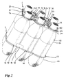
- FIG. 1 shows a plan view of a first embodiment of a handle 1 for six bottles 100, which in FIG. 2 are shown.
- the carrying handle 1 has six receiving elements 2a to 2f for receiving the bottle heads 102. Furthermore, the carrying handle has a gripping element 3, which extends between the receiving elements 2a to 2f. On the outside, the receiving elements are surrounded by a ring element 4. Between the individual receiving elements 2a to 2f 4 stiffening webs 5, 6, 7, 8, 9, 10 are provided with an edge approximately parallel to the ring member.
- the stiffening webs 5 to 9 have an approximately parallel to the ring member extending edge and extending with flat curved portions 50, 51, 60, 61, 70, 71, 80, 81, 90, 91 between the respective adjacent receiving elements.
- the stiffening web 10 is formed bent between the two receiving elements 2a and 2f.
- an identification flag 11 as an embodiment of an identification element for characterizing the later packaging unit of carrying handle and bottles is disposed on the ring member 4 and also extends into the space between the two receiving members 2a and 2f.
- an identification band or another form of identification element can be provided which is or is connected in a suitable manner to the carrying handle, in particular ring element.
- the identification flag 11 is arranged on a portion 40 of the ring element, which is connected via two torsion points 41, 42 to the rest of the ring element 4. About the two torsion points, it is possible to bend out the portion 40 with the identification flag 11 from the plane of the handle. As a result, a slight hiring of Ken Vietnamesesfähnchens in the later position of the ring member is possible, which is separated from the rest of the handle and along the bottles with respect to this pushed down to keep the bottles together also in the lower area. The final position of the flag 11 may be better FIG. 2 be removed.
- the identification flag 11 is here at an angle of about 65 ° relative to the horizontal. In such a position, an easy detection of the contents of the identification flag, eg the data of the packaging unit, including price data, eg by a scanner cash register, is possible.
- the grip element 3 surrounding, further connecting webs 12, 13, 14, 15, 16, 17 are provided. All connecting webs have a curved shape, wherein the connecting webs 12 to 16 are supported by further planar stiffening sections 120, 121, 130, 131, 140, 141, 150, 151, 160, 161 relative to the receiving elements 2a to 2f. Only the connecting web 17, which is arranged in the region of the identification flag 11, has no further stiffening sections. In principle, however, this could also have further stiffening sections, which are omitted for reasons of space here.
- the grip element 3 has a straight in the plan view middle holding portion 30 which is secured via four torsion bars 31, 32, 33, 34 to the connecting webs 13, 14, 16, 17.
- the attachment takes place via respective torsion points 35, 36, 37, 38.
- the middle holding portion 30 of the handle member 3 has a slightly curved shape in the side view, which better the FIG. 2 can be removed. By this slightly curved shape of the middle holding portion centering when stacking several carrying handles on each other for storage in a simple manner possible.
- the individual receiving elements can be designed accordingly to facilitate stacking.
- the receiving elements 2a to 2f each have retaining tabs 20 which engage on the underside of a protruding portion on the bottle head, which in FIG. 2 you can see.
- the retaining tabs 20 protrude inward from a circumferential retaining ring 21 and are, as well FIG. 2 can be better taken out of the plane of the handle out slightly inclined.
- retaining tabs 20 also other holding devices may be provided, such as retaining lugs or webs.
- retaining lugs or webs instead of the respective nine retaining tabs, a different number of retaining tabs can be provided, in particular when providing a different shape for this.
- the shape can also be chosen here arbitrarily, in particular, an adaptation to the respective bottle neck shape or bottle head shape is possible here.
- the surrounding the carrying handle ring member 4 is what the top view in FIG. 1 can not be removed, formed in cross-section approximately V-shaped to have a sufficient support surface 43 when pushing down the ring member along the bottles.
- the ring element is not rectangular in cross-section or square, so that can be saved by the V-shape over such a square or rectangular cross-sectional shape material.
- the ring member 4 is further secured via web members 44, 45, 46 to the remainder of the carrying handle, namely the stiffening webs 6, 7, 9.
- a respective predetermined breaking point 47, 48, 49 is provided between the web elements 44 to 46 and the stiffening webs 6, 7, 9.
- the ring element can be made of such an elastic material that after pushing down, thus stretching of the ring element in the area of the bulges 101 of the bottles 100, it springs back again into its original unstretched form. If the ring element does not have such an elasticity, a closure device 110 is provided for closing, that is, lashing the ring element around the bottles.
- a closure device 110 is in one embodiment in FIG. 1 also shown. This has a paragraph 111 provided with housing 111. Further, it has a closure part 113 which is formed arrow-shaped, wherein it has a tapered projection 114 at its front end. Furthermore, it has a further projection 115 along its longitudinal extension, which can engage in the housing 112 in a corresponding recess 116.
- the closure member 113 is inserted into the housing 112 and locked in the desired paragraph 111 with its front projection 114. Due to the latching an unintentional release is no longer possible here, so that the closure device ensures that the container or bottles 100 of the ring element 4 tightly enclosed.
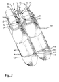
- This may also be the perspective view in FIG. 3 be removed. Here, the latched position of the closure device is shown. According to the embodiment in FIG. 3 can the case on its top open, so that the proper locking within the housing is visible from the outside. Likewise, the housing 112 may be formed closed.
- corresponding devices may be provided in automatic placement machines or the device for applying the carrying handles to the containers, via slide elements or corresponding other devices in the region of the housing 112 and in the region of the closure part 113 attacks and move them against each other until a close concern of the ring member 4 is done around the bottles around.
- FIG. 4 shows an alternative embodiment of a carrying handle 200 which is adapted to receive six cans.
- six receiving elements 2a to 2f are formed, but provide shorter retaining tabs 245, since usually the upper edge is less pronounced in doses as a circumferential projection in beverage bottles.
- each stiffening webs 205 to 210 are also provided.
- these are all formed uniformly, since a flag ID 211 is disposed within the receiving element 2d.
- the stiffening webs 205 to 210 are each formed as narrow, slightly curved webs between the individual receiving elements 2a to 2f.
- the individual receiving elements also arranged in the inner region of the handle connecting webs 212 to 217 are provided.
- each further connecting webs 218, 219, 220, 221 are provided between the respective stiffening webs and connecting webs on the outside and inside of the carrying handle. They are wider than the stiffening and connecting webs, so that over this a stiffening of the entire handle is possible.
- the two receiving elements 2c and 2f are also connected via a further connecting web 222 connected together to stiffen the middle portion of the handle.
- the carrying handle has two handle members 230, 231. Both are arranged within a respective receiving element, namely within the receiving elements 2c and 2f. Both gripping elements are mirror-symmetrical to each other and each have a central web 232, 233 and from this v-shaped mutually extending torsion bars 234, 235, 236, 237 on. These are fastened via respective torsion points 238 to the receiving elements 2c and 2f.
- the gripping elements 230, 231 Due to the V-shape of the torsion bars and the further bending relative to the respective central webs of the gripping elements 230, 231, these can in turn be telescoped out of the plane of the carrying handle when pulled out of the plane of the carrying handle, and in turn via the torsion points the torsion bars and thereby results in an approximately parallel extraction of the central webs 232, 233 from the plane of the carrying handle.
- the two gripping elements 230, 231 are brought together in the direction of the connecting web 222 between the two receiving elements 2c and 2f and can then be grasped by a hand of a carrying person and the packaging unit of carrying handle and six cans can be comfortably carried.
- the identification flag 211 or in the carrying handle according to Figure 1 to 3 the identification flag 11 is provided. On this a corresponding code can be printed or otherwise applied. Alternatively, it is also possible to introduce here an RFID transponder in the identification flag, which contains the desired data.
- the identification flag 211 is arranged via telescopic webs 240 to 243 within the receiving element 2d.
- the telescopic webs 240 are serpentine curved back and forth, so that pushing out of the identification flag 11 from the plane of Carrying handle is easily possible. This is done automatically when a can head is inserted into the receiving element 2d.
- it also proves to be advantageous to connect the four telescopic webs 240 to 243 via corresponding torsion points 244 on the receiving element 2d or its retaining tabs 245.
- FIG. 5 Another embodiment of a carrying handle 300 is shown in FIG. 5 for wearing a 5 liter drum, for example.
- a receiving element 302 is provided.
- This also has retaining tabs 320.
- an unillustrated receiving ring may be provided, from which protrude the retaining tabs in the interior of the receiving element.
- the retaining tabs are here, as well as in the embodiment of the handle for cans according to FIG. 4 , formed relatively short towards the interior of the receiving element, since the edge of a 5 liter drum is formed relatively narrow, so that these short retaining tabs for reaching under the edge of this sufficient.
- the carrying handle according FIG. 5 is also provided with a handle member 330. This is attached at two mutually approximately opposite points on the outside of the receiving element 302 via torsion points 331, 332. In the rest position, the gripping element 330 lies in the plane of the receiving element 302.
- the gripping element 330 has a slightly wider central holding section 333 and two webs 334, 335 extending therefrom to the two torsion points 331, 332.
- the middle holding web 333 can be held in a parallel plane above the plane of the receiving element 302.
- there is advantageously no deformation of the middle holding web 333 so that a comfortable carrying position can be achieved.
- Carrying handles serve for receiving six containers in the form of bottles or cans or other containers which fit into the receiving elements.
- embodiments may also be provided in which less or more containers than packaging unit to be packed.
- the provision of carrying handles for four cans or four bottles is possible.
- the identification flag 211 may be placed in a central inner opening of the carrying handle, so it need not be placed within a receiving element.
- the handle member may be disposed in the region of the central inner opening within the carrying handle, instead of the arrangement in two adjacent receiving elements, as in FIG. 4 shown. It can also be provided here only a handle element, since this is sufficient for a handle for four doses.
- All handles can be made of HDPE or of any other suitable material, in particular plastic material.
- each of the handle element is telescoped out of the plane of the handle, at least two torsion points on the handle or at least one ring element for surrounding the outside of the container , which are detachably attached to the carrying handle, or in which at least one identification element, such as a identification flag, identification band, etc., is arranged on the carrying handle or a packaging unit of a plurality of containers.
- at least one identification element such as a identification flag, identification band, etc.
- corresponding carrying handles for other packaging unit sizes can be formed, in which in each case likewise a ring element or identification element or a corresponding grip element fastened to the carrying handle via torsion points are provided. All mentioned in the foregoing and shown in the figures features can be combined with each other.
Landscapes
- Engineering & Computer Science (AREA)
- Mechanical Engineering (AREA)
- Details Of Rigid Or Semi-Rigid Containers (AREA)
Abstract
Description
Die Erfindung betrifft einen Tragegriff für einen oder mehrere Behälter mit zumindest einem Griffelement und zumindest einem Aufnahmeelement zur Aufnahme des zumindest einen Behälters, eine Verpackungseinheit sowie eine Vorrichtung zum Aufbringen von entsprechenden Tragegriffen auf Behälter.The invention relates to a carrying handle for one or more containers with at least one gripping element and at least one receiving element for receiving the at least one container, a packaging unit and a device for applying corresponding handles to containers.
Derartige Tragegriffe sind im Stand der Technik zahlreich bekannt. Beispielsweise geht aus der
Aus der
Aus der
Die
Die
Aus der
Die
Auch der in der
Auch der aus der
Aus der
Aus der
Die
Die
In der
Die
Ein Träger zum Tragen von zwei tubenartigen Behältern ist in der
Eine weitere Möglichkeit eines Trägers für Flaschen ist in der
Ein weiterer Träger zum Tragen mehrerer Flaschen ist in der
Die
All diejenigen Träger des Standes der Technik, die ein Eingreifen durch Daumen und einen Finger der Hand des Tragenden vorsehen, erweisen sich bei der Verwendung gerade für mehrere Flaschen aufgrund der einschneidenden Wirkung der Tragelaschen oder Öffnungen des Trägers in die Hand des Tragenden als nachteilig. Umgekehrt erweist sich das Vorsehen von starren Griffelementen oder Handgriffen beim Stapeln mehrerer Träger als nachteilig, da diese verhältnismäßig viel Platz einnehmen.All those prior art carriers that provide for intervention by the thumb and finger of the wearer's hand prove disadvantageous in use for just a few bottles due to the incising effect of the wearer's latches or openings in the wearer's hand. Conversely, the provision of rigid handle elements or handles when stacking multiple carriers proves to be disadvantageous because they occupy a relatively large amount of space.
Der vorliegenden Erfindung liegt daher die Aufgabe zugrunde, einen Tragegriff nach dem Oberbegriff des Anspruchs 1 dahingehend fortzubilden, dass eine sehr gute Stapelbarkeit mehrerer Tragegriffe übereinander möglich ist und zugleich ein komfortables Angreifen an dem Tragegriff zum Tragen auch mehrerer Behälter, insbesondere Flaschen, wobei gerade beim Tragen mehrerer Flaschen eine kompakte gut zu tragende Verpackungseinheit geschaffen sein soll.The present invention is therefore based on the object to further develop a carrying handle according to the preamble of
Die Aufgabe wird durch einen Tragegriff nach dem Oberbegriff des Anspruchs 1 dadurch gelöst, dass das Griffelement aus der Ebene des Tragegriffs heraus teleskopierbar über zumindest zwei Torsionsstellen am Tragegriff angeordnet ist. Für eine Verpackungseinheit nach dem Oberbegriff des Anspruchs 20 wird die Aufgabe dadurch gelöst, dass die Behälter von einem Ringelement umgeben sind. Weiterbildungen der Erfindungen sind in den abhängigen Ansprüchen definiert.The object is achieved by a carrying handle according to the preamble of
Dadurch wird ein Tragegriff für einen oder mehrere Behälter mit zumindest einem Griffelement und zumindest einem Aufnahmeelement zur Aufnahme des zumindest einen Behälters geschaffen, bei dem das Griffelement im unbenutzten Zustand des Tragegriffs in der Ebene von diesem liegt und erst für die Benutzung des Tragegriffs, also das Auffügen auf Behälter, das Griffelement aus der Ebene des Tragegriffs herausgezogen wird, wobei es im Unterschied zum Stand der Technik über zumindest zwei Torsionsstellen am Tragegriff herausteleskopiert wird. Der Vorteil besteht darin, dass das Griffelement dadurch sich nicht u-förmig über der Ebene des Tragegriffs ausformt, sondern durch das Teleskopieren oder "Entwringen" ein mittlerer Abschnitt des Griffelements weiterhin im Wesentlichen gerade bleibt und damit durch die tragende Person besser angegriffen werden kann als ein sich u-förmig ausbildendes Griffelement, das üblicherweise in Zeigefinger und kleinen Finger der Hand des Trägers einschneidet und dadurch zu einem schlechten Tragekomfort führt. Vorteilhaft kann das Griffelement so weit aus der Ebene des Tragegriffs heraus teleskopiert werden, dass der Abstand zwischen dem Griffelement und der obersten Erstreckung von zumindest einem in dem Tragegriff aufgenommenen Behälter das Einfügen einer Hand einer tragenden Person zulässt. Somit kann die tragende Person bequem über der obersten Erstreckung der in dem Tragegriff aufgenommenen Behälter unter das Griffelement greifen und die Verpackungseinheit tragen. Es wird also ein solcher Abstand zwischen Griffelement und Ebene des Tragegriffs vorgesehen, dass eine Hand eines Trägers bzw. einer tragenden Person bequem nach der Aufnahme von Behältern in dem Tragegriff das Griffelement untergreifen kann. Im Stand der Technik ist ein solch ausreichender Platz für das Angreifen an den dortigen Griffelementen nicht gegeben. Vielmehr liegen dort die in die Grifflaschen eingekrallten Finger der Hand einer tragenden Person bzw. eines Trägers stets unbequem zwischen Flaschenhälsen oder Behälterköpfen.As a result, a carrying handle for one or more containers is provided with at least one gripping element and at least one receiving element for receiving the at least one container, wherein the gripping element is in the unused state of the carrying handle in the plane thereof and only for the use of the carrying handle, so the Attaching to the container, the handle element is pulled out of the plane of the carrying handle, wherein it is in contrast to the prior art heraustelkoped at least two torsion points on the carrying handle. The advantage is that the handle element thereby does not form U-shaped over the plane of the handle, but by telescoping or "Entwringen" a central portion of the handle element remains substantially straight and thus can be better attacked by the person wearing a U-shaped handle forming element which usually cuts into the forefinger and small finger of the hand of the wearer and thereby leads to a poor wearing comfort. Advantageously, the gripping element can be telescoped out of the plane of the carrying handle so far that the distance between the gripping element and the uppermost extent of at least one container received in the carrying handle permits the insertion of a hand of a carrying person. Thus, the carrying person can conveniently reach over the uppermost extent of the container received in the carrying handle under the gripping element and carry the packaging unit. It is therefore provided such a distance between the handle element and the plane of the carrying handle that a hand of a wearer or a person wearing can comfortably grip the grip element after receiving containers in the carrying handle. In the prior art, such a sufficient space for attacking the local handle elements is not given. On the contrary, the fingers of the hand of a carrying person or of a wearer who are clasped in the grip bottles are always uncomfortable between bottle necks or container heads.
Für die Stapelfähigkeit der Tragegriffe vor dem Auffügen auf Behälter erweist sich das Liegen in der Ebene des Tragegriffs für das Griffelement als sehr vorteilhaft, insbesondere gegenüber den Tragegriffen des Standes der Technik, bei denen die Griffelemente starr über der Ebene des Tragegriffs vorstehen. Der Platzbedarf für ein solches Griffelement des Standes der Technik ist daher sehr viel größer als bei dem erfindungsgemäßen, das zu keinem größeren Platzbedarf für den Tragegriff führt. Dies erweist sich nicht nur in Bestückungsautomaten, sondern natürlich auch bei der Lagerhaltung als äußerst vorteilhaft.For the stackability of the handles before mounting on containers, the lying in the plane of the handle for the handle element proves to be very beneficial, especially with respect to the handles of the prior art, in which the gripping elements project rigidly over the plane of the carrying handle. The space required for such a grip element of the prior art is therefore much larger than in the invention, which does not lead to a larger footprint for the carrying handle. This proves to be extremely advantageous not only in pick and place machines, but of course also in warehousing.
Das Griffelement weist vorteilhaft zumindest einen leicht gekrümmten Abschnitt zum Zentrieren beim Stapeln von mehreren Tragegriffen aufeinander auf. Eine weitere Stapelhilfe zum Erleichtern eines Zentrierens der Tragegriffe aufeinander kann dadurch vorgesehen werden, dass die Aufnahmeelemente zur Aufnahme der Behälter, das heißt von deren Kopfabschnitten, nicht vollständig eben ausgebildet sind, sondern eine leichte Neigung aufweisen. Das zumindest eine Aufnahmeelement zur Aufnahme des zumindest einen Behälters ist vorteilhaft kragenförmig mit nach innen ragenden Haltelaschen oder Haltenasen ausgebildet. Somit können sowohl die nach innen ragenden Haltelaschen oder Haltenasen eine leichte Neigung aufweisen als auch der umlaufende Kragen der Aufnahmeelemente, wodurch eine Selbstzentrierung in diesem Bereich von aufeinander gestapelten Tragegriffen erreicht werden kann.The grip element advantageously has at least one slightly curved section for centering when stacking a plurality of carrying handles on each other. Another stacking aid for facilitating centering of the carrying handles on each other can be provided that the receiving elements for receiving the container, that is, of the head portions, not completely flat, but have a slight inclination. The at least one receiving element for receiving the at least one container is advantageously formed like a collar with inwardly projecting retaining tabs or retaining lugs. Thus, both the inwardly projecting retaining tabs or retaining lugs may have a slight inclination and the circumferential collar of the receiving elements, whereby a self-centering can be achieved in this area of stacked carrying handles.
Als weiter vorteilhaft erweist es sich, bei Vorsehen mehrerer Aufnahmeelemente diese durch bezüglich des Tragegriffs außenseitig angeordnete Versteifungsstege untereinander zu verbinden. Hierdurch wird eine besondere Stabilität des gesamten Tragegriffs erzielt, was ein seitliches Ausbrechen der in den Tragegriff eingefügten Behälter zumindest einschränken kann. Auch ein ungewolltes Verwinden des Tragegriffs kann hierdurch vermieden werden. Insbesondere sind nicht nur die bezüglich des Tragegriffs außenseitig angeordneten Versteifungsstege zwischen den einzelnen Aufnahmeelementen zur Aufnahme der Behälterhälse beziehungsweise -köpfe vorgesehen, sondern auch noch weitere Verbindungsstege zwischen den einzelnen Aufnahmeelementen im inneren Bereich des Tragegriffs. Das Griffelement kann daher an dem zumindest einen Aufnahmeelement und/oder den Verbindungsstegen und/oder den Versteifungsstegen befestigt sein. Die Befestigung erfolgt in jedem Falle über die bereits erwähnten Torsionsstellen, um das teleskopartige Anheben des Griffelements etwa parallel zur Ebene des Tragegriffs zu ermöglichen und ein Ausbeulen des Griffelements zu verhindern.It proves to be further advantageous, when several receiving elements are provided, to connect them to one another by means of stiffening webs arranged on the outside with respect to the carrying handle. As a result, a particular stability of the entire carrying handle is achieved, which can at least limit a lateral breaking out of the container inserted into the carrying handle. An unintentional twisting of the carrying handle can be avoided thereby. In particular, not only with respect to the carrying handle on the outside arranged stiffening webs between the individual receiving elements for receiving the container necks or heads are provided, but also further connecting webs between the individual receiving elements in the inner region of the carrying handle. The gripping element can therefore be attached to the at least one receiving element and / or the connecting webs and / or the stiffening webs. The attachment takes place in any case on the already mentioned torsion points to the telescopic lifting of the To allow grip element approximately parallel to the plane of the handle and to prevent buckling of the handle member.
Mit den Tragegriffen können sogenannte Multipacks erzeugt werden von beispielsweise vier oder sechs gruppierten Behältern, insbesondere Flaschen oder Dosen. Grundsätzlich lässt sich auch beispielsweise nur ein Fass mit einem solchen Tragegriff versehen, wobei auch dieses, beispielsweise ein 5 Liter Party-Bierfass, mit seinem oberen Rand in einem Aufnahmeelement aufgenommen wird. Das Griffelement wird beidseitig, also an einander gegenüberliegenden Stellen, an dem Aufnahmeelement angeformt über Torsionsstellen oder Torsionsknoten, so dass beim Angreifen an dem Griffelement dieses sich in seine Position "entwringt", also an den Torsionsstellen tordiert wird und damit nicht beult, sondern seine gewünschte gut handhabbare Form beibehält, ohne eine O-Form zu bilden.With the carrying handles so-called multipacks can be produced, for example, four or six grouped containers, especially bottles or cans. In principle, for example, only a barrel can be provided with such a carrying handle, whereby this, for example, a 5 liter party beer keg, is recorded with its upper edge in a receiving element. The gripping element is formed on both sides, ie at opposite points on the receiving element via torsion or torsion, so that when attacking the handle element this "twisted" into its position, that is twisted at the torsion and thus does not buckle, but his desired maintains a manageable shape without forming an O-shape.
Für die Aufnahme von Dosen können insbesondere zwei teleskopierbar an den Tragegriff angeordnete Griffelemente vorgesehen sein, die entweder zueinander geführt und aneinander befestigt bzw. verrastet werden können oder so aus der Ebene des Tragegriffs herausteleskopiert werden, dass ein komfortables Angreifen durch die Hand einer tragenden Person möglich ist. Beim Ergreifen beider Griffelemente durch eine Hand werden die beiden Griffelemente vorteilhaft über die jeweils zwei Torsionsstellen aus der Ebene des Tragegriffs herausteleskopiert und zueinander geführt, so dass sie etwa mittig über dem Tragegriff für die Dosen, insbesondere sechs Dosen, zusammenkommen und zentral durch eine Hand der tragenden Person ergriffen und die Verpackungseinheit aus beispielsweise sechs Dosen hierüber getragen werden kann.For receiving cans in particular two telescopically arranged on the carrying handle gripping elements may be provided, which can either be guided and locked to each other or latched or so out of the plane of the handle are herausteleskopkop that a comfortable attack by the hand of a person wearing possible is. When gripping both handle elements by a hand, the two handle elements are advantageous about the two torsion out of the plane of the carrying handle herausteleskopiert and each other so that they come together in the middle about the carrying handle for the cans, especially six cans, and centrally by a hand of wearing person and the packaging unit can be worn over example, six cans over it.
Die jeweiligen Torsionspunkte an den Griffelementen dienen als Aufrichthilfe. Grundsätzlich kann auch eine andere Einrichtung oder ein anderer Mechanismus vorgesehen werden, um dasselbe Ziel zu erreichen, nämlich ein Teleskopieren des Griffelements im Bereich seines mittleren Griffstegs etwa parallel zur Ebene des Tragegriffs, um ein Beulen des Griffelements und somit eine unkomfortable Haltung beim Tragen des Tragegriffs für den Träger zu vermeiden.The respective torsion points on the handle elements serve as Aufrichthilfe. In principle, another device or another mechanism can be provided in order to achieve the same goal, namely a telescoping of the handle member in the region of its central handle bar approximately parallel to the plane of the handle, to a buckling of the handle member and thus an uncomfortable attitude when carrying the handle for the wearer to avoid.
Als weiter vorteilhaft erweist es sich, wenn bei einem Tragegriff für einen oder mehrere Behälter mit zumindest einem Griffelement und zumindest einem Aufnahmeelement zur Aufnahme des zumindest einen Behälters, zumindest ein Ringelement zum außenseitigen Umgeben der Behälter lösbar an dem Tragegriff befestigt ist. Dieses Ringelement umgibt die Aufnahmeelemente und die zwischen diesen angeordneten Versteifungs- bzw. Verbindungsstege, ist also außenseitig von diesen angeordnet. Das Ringelement ist sozusagen als äußere Umgrenzung des Tragegriffs vorgesehen und kann von diesem abgetrennt werden. Hierzu ist es vorteilhaft durch Stegelemente mit dem zumindest einen Aufnahmeelement und/oder den Versteifungsstegen lösbar verbunden. Zum Erzeugen der Lösbarkeit ist vorzugsweise eine Sollbruchstelle zwischen Ringelement und Stegelementen vorgesehen bzw. zwischen den Stegelementen und dem zumindest einen Aufnahmeelement und/oder den Versteifungsstegen. Durch Durchbrechen der Sollbruchstellen kann das Ringelement von dem Rest des Tragegriffs abgetrennt und entlang den Behältern auf deren Außenseite so weit herunter geschoben werden, dass diese einen guten äußeren Halt gegen ein Ausbrechen aus dem Behälterverband nach außen erfahren. Das Ringelement wird somit anstelle von Banderolen oder Schrumpffolie zum Halten der Behälter aneinander vorgesehen. Da es beim Formen des Tragegriffs an diesem mit angeformt wird, ist kein zusätzliches Material für das Ringelement erforderlich. Vielmehr kann auf einfache Art und Weise mittels einer Vorrichtung zum Aufbringen der Tragegriffe auf Behälter, insbesondere einen Bestückungsautomaten, über eine Einrichtung zum Angreifen an dem Ringelement des Tragegriffs ein Herabschieben von diesem entlang den Behältern erfolgen. Der Tragegriff wird somit auf eine Gruppe von Behältern, die vorteilhafterweise bereits entsprechend positioniert sind, um mit ihren Behälterköpfen bzw. -hälsen in die Aufnahmeelemente zu passen, aufgefügt, so dass die Behälterköpfe durch die Aufnahmeelemente ragen. Beim Auffügen des Tragegriffs auf die Behälter ergreift die Einrichtung zum Angreifen an dem Ringelement dieses und reißt es beim weiteren Herabfahren von dem Rest des Tragegriffs ab, wobei die Sollbruchstellen zerbrechen. Beim Weiterbewegen schiebt sie das Ringelement so weit an den entlang Behältern herab, dass entweder eine vorgebbare Auflagestelle an den Behältern erreicht wird oder eine vordefinierte Position von dem Ringelement eingenommen wird.It proves to be further advantageous if, in the case of a carrying handle for one or more containers with at least one gripping element and at least one receiving element for receiving the at least one container, at least one ring element for surrounding on the outside is detachably fastened to the carrying handle. This ring element surrounds the receiving elements and arranged between them stiffening or connecting webs, that is arranged on the outside of this. The ring element is provided, so to speak, as an outer boundary of the carrying handle and can be separated from this. For this purpose, it is advantageously releasably connected by web elements with the at least one receiving element and / or the stiffening webs. To generate the solubility preferably a predetermined breaking point between the ring element and web elements is provided or between the web elements and the at least one receiving element and / or the stiffening webs. By breaking the predetermined breaking points, the ring element can be separated from the rest of the carrying handle and pushed down along the containers on the outside so far that they experience a good external grip against breaking out of the container structure to the outside. The ring member is thus provided instead of bands or shrink film for holding the containers together. Since it is molded with the molding of the handle on this, no additional material for the ring member is required. Rather, in a simple manner by means of a device for applying the carrying handles to containers, in particular a placement machine, via a device for engaging the ring member of the carrying handle a downshift of this carried along the containers. The carrying handle is thus placed on a group of containers, which are advantageously already positioned accordingly to fit with their container heads or necks into the receiving elements, so that the container heads protrude through the receiving elements. When attaching the carrying handle to the container engages the means for engaging the ring member this and tearing it from further down the rest of the handle from, breaking the predetermined breaking points. As it moves onward, it pushes the ring element down so far along the containers that either a predefinable contact point is reached on the containers or a predefined position is assumed by the ring element.
Ist für den Tragegriff und insbesondere das Ringelement ein solches Material gewählt, dass ein Dehnen oder Spreizen des Ringelements beim Herabschieben entlang den Behälterwänden nach dem Erreichen der Endposition für das Ringelement, also bei Wegfall der Dehnkraft sofort wieder zu einem Zusammenziehen führt, legt sich das Ringelement direkt an die äußeren Oberflächen von diesem umgebenen Behälter an. Weist das Material des Ringelements eine solche Eigenschaft jedoch nicht auf, wird am Ringelement vorteilhaft zumindest eine Verschlusseinrichtung zum Befestigen an den Behältern vorgesehen. Die Verschlusseinrichtung kann von einer Einrichtung zum Verschließen der Vorrichtung zum Aufbringen der Tragegriffe erfasst und nach dem Herabschieben des Ringelements entlang den Behältern verschlossen werden. Dieses Verschließen kann durch eine aufeinander zugerichtete Bewegung von Teilen der Einrichtung zum Verschließen der Verschlusseinrichtung durchgeführt werden. Zu diesem Zweck kann die Einrichtung zum Verschließen der Verschlusseinrichtung Schiebelemente umfassen, die an zwei Enden der Verschlusseinrichtung angreifen und diese durch aufeinander zu gerichtete Bewegung verschließen. Anstelle von Schiebeelementen können auch andere Einrichtungen vorgesehen werden, die ein Verschließen der jeweiligen Verschlusseinrichtung ermöglichen.Is selected for the carrying handle and in particular the ring member such a material that a stretching or spreading of the ring member when pushed down along the container walls after reaching the end position for the ring element, ie immediately eliminates the expansion force when the elastic force disappears, the ring element sets directly to the outer surfaces of this surrounded container. However, if the material of the ring element does not have such a property, at least one closure device for fastening to the containers is advantageously provided on the ring element. The closure device can be detected by a device for closing the device for applying the carrying handles and can be closed after the ring element has been pushed down along the containers. This closing may be accomplished by a juxtaposed movement of parts of the means for closing the closure means. For this purpose, the means for closing the closure means may comprise sliding elements which engage two ends of the closure means and close them by movement towards each other. Instead of sliding elements, other means can be provided which allow a closure of the respective closure device.
In einer Ausführungsform kann die Verschlusseinrichtung zumindest ein mit Widerhaken versehenes Element und zumindest ein damit zusammenwirkendes Gegenelement umfassen. Das mit Widerhaken versehene Element wird gegen das damit zusammenwirkende Gegenelement gedrückt, so dass sich beide Elemente ineinander verhaken und zum Verschließen der Verschlusseinrichtung und somit Schließen des Ringelements führen. Alternativ oder zusätzlich kann die Verschlusseinrichtung vorteilhaft eine Verrastungseinrichtung enthalten, insbesondere ein mit Absätzen versehenes Gehäuseteil und ein darin einschiebbares mit zumindest einer außenseitigen Auskragung versehenes Verschlussteil aufweist. Das mit der zumindest einen außenseitigen Auskragung versehene Verschlussteil wird zum Verschließen des Ringelements in das Gehäuseteil eingeschoben und verrastet darin hinter den Absätzen des Gehäuseteils. Hierdurch ist beispielsweise auch eine Anpassung an unterschiedliche Umfänge, die von dem Ringelement umschlossen werden sollen, möglich, da das mit der zumindest einen außenseitigen Auskragung versehene Verschlussteil hinter verschiedenen Absätzen des Gehäuseteils verrastet werden kann.In one embodiment, the closure device may comprise at least one barbed element and at least one mating element cooperating therewith. The barbed element is pressed against the counter-element cooperating therewith, so that both elements interlock with one another and lead to closure of the closure device and thus closure of the ring element. Alternatively or additionally, the closure device may advantageously comprise a latching device, in particular a housing part provided with shoulders and a closure part which can be inserted therein and is provided with at least one outside projection. The closure part provided with the at least one outer-side projection is used to close the ring element in the Housing part inserted and locked behind the heels of the housing part. As a result, for example, an adaptation to different circumferences that are to be enclosed by the ring element, possible because the provided with the at least one outer side projection locking part can be locked behind different paragraphs of the housing part.
Eine weitere Möglichkeit eines Verschließens des Ringelements um die Behälter herum besteht darin, das Ringelement mit einem Abschnitt mit ineinander hakbaren Widerhaken zu versehen. Das Ringelement ist hierbei geschlossen ausgebildet und weist den Abschnitt als beispielsweise v-förmig geknickten Abschnitt auf. Die Widerhaken können beim weiteren Zusammendrücken des v-förmigen Abschnitts ineinander verhakt werden, so dass hierdurch eine Reduzierung der Länge des Ringelements und entsprechend ein gewünschtes festes Umgreifen der Behälter durch das Ringelement ermöglicht wird.Another way of closing the ring element around the containers is to provide the ring element with a section of barbs hooked into one another. The ring element is in this case formed closed and has the portion as an example V-shaped bent portion. The barbs can be hooked into each other upon further compression of the V-shaped portion, so that thereby a reduction in the length of the ring member and, correspondingly, a desired firm embrace of the container is made possible by the ring member.
Eine weitere auch mit den anderen Varianten kombinierbare Möglichkeit besteht darin, eine Verschlusseinrichtung nach Art einer Perlenschnur mit aneinander gereihten Elementen, insbesondere konischen Elementen vorzusehen. Derartige konische Elemente können beispielsweise so aneinander angreifen, dass sie sich wie Widerhaken aneinander verhaken und hierdurch ein Verschließen ermöglichen.Another possibility, which can also be combined with the other variants, is to provide a closure device in the manner of a string of pearls with elements lined up in a row, in particular conical elements. Such conical elements, for example, attack each other so that they hooked like barbs together and thereby allow a closure.
Vorteilhaft weist das Ringelement zum Erzeugen einer Abstützungsfläche zum Angreifen beim Herabschieben entlang den Behälterwänden eine obere Abstützfläche auf, insbesondere ist das Ringelement im Querschnitt v-förmig. Durch das Vorsehen einer solchen Abstützungsfläche an dem Ringelement in dem Bereich, in dem die Einrichtung zum Herabschieben angreift, ist für diese eine bessere Kraftausübung auf das Ringelement zum Trennen von dem restlichen Tragegriff möglich. Durch das Ausbilden des Ringelements als im Querschnitt etwa v-förmiges Element wird einerseits eine solche Abstützungsfläche geschaffen, andererseits jedoch so wenig wie möglich an Material hierfür verbraucht. Alternativ kann das Ringelement beispielsweise auch im Querschnitt T-förmig ausgebildet werden, wobei wiederum eine obere Abstützungsfläche bei möglichst wenig zusätzlichem Materialverbrauch geschaffen werden kann. Bei einem T-förmigen Querschnitt könnte es jedoch bei ungleichmäßiger Kraftausübung auf diesen zu einem einseitigen Einknicken der Abstützungsfläche kommen, was bei einem v-förmigen Querschnitt im Allgemeinen aufgrund seiner höheren Stabilität nicht auftreten wird. Aus diesem Grunde wird trotz des etwas höheren Materialverbrauchs ein v-förmiger Querschnitt gegenüber einem T-förmigen Querschnitt bevorzugt.Advantageously, the ring element for generating a support surface for engaging when pushed down along the container walls on an upper support surface, in particular, the ring element in cross-section is V-shaped. By providing such a support surface on the ring member in the region in which the means for pushing down attacks, for this a better application of force to the ring member for separating the remaining handle is possible. By forming the ring element as a cross-sectionally approximately v-shaped element, on the one hand, such a support surface is created, on the other hand, however, consumed as little as possible of material for this purpose. Alternatively, the ring element can for example also be formed in cross-section T-shaped, in turn, an upper Support surface can be created with as little additional material consumption. However, with a T-shaped cross-section, uneven application of force to the support surface could result in a one-sided buckling of the support surface, which in general will not occur with a V-shaped cross section due to its higher stability. For this reason, in spite of the somewhat higher material consumption, a V-shaped cross section is preferred over a T-shaped cross section.
Die außenseitigen Versteifungsstege können insbesondere als Sekanten zwischen den einzelnen Aufnahmeelementen ausgebildet sein. Hierdurch ist eine weitere Materialeinsparung möglich. Ferner wird es für die an dem Ringelement angreifende Einrichtung der Vorrichtung zum Aufbringen der Tragegriffe auf die Behälter leichter möglich, zwischen das Ringelement und entsprechende Öffnungen in dem Tragegriff im Bereich der Versteifungsstege zu greifen, wenn diese etwa parallel zueinander angeordnet sind.The outside stiffening webs may be formed in particular as secants between the individual receiving elements. As a result, further material savings is possible. Further, for the device acting on the ring element of the device for applying the carrying handles to the container, it becomes more easily possible to grip between the ring element and corresponding openings in the carrying handle in the region of the stiffening webs, when these are arranged approximately parallel to one another.
Ein Ringelement ist nicht bei allen Arten von Behältern erforderlich, sondern insbesondere bei größerformatigen Behältern, die anderenfalls dazu neigen, in dem nicht in dem Tragegriff aufgenommenen Abschnitt sich voneinander weg zu bewegen. Dies ist insbesondere bei größeren Getränkeflaschen der Fall, weswegen es sich hier besonders eignet, einen Tragegriff mit einem solchen Ringelement zu verwenden, wobei das Ringelement das Auseinandergleiten der größerformatigen Getränkeflaschen verhindert. Ein Stapeln derartiger Verpackungseinheiten aus beispielsweise sechs Getränkeflaschen ist problemlos möglich, da das Ringelement so angeordnet ist, dass kein zusätzlicher Platzbedarf erforderlich ist, sondern vielmehr in gewohnter Art und Weise ein Bestücken einer Palette möglich ist.A ring member is not required in all types of containers, but especially in larger-sized containers, which otherwise tend to move away from each other in the portion not received in the carrying handle. This is particularly the case with larger bottles of beverage, which is why it is particularly suitable here to use a carrying handle with such a ring element, wherein the ring element prevents the larger-sized beverage bottles sliding apart. A stacking of such packaging units, for example, six bottles of beverage is easily possible because the ring element is arranged so that no additional space is required, but rather in the usual way, a populating a pallet is possible.
Als weiter vorteilhaft erweist es sich, zumindest ein Kennungselement, insbesondere Kennungsfähnchen oder Kennungsband, an dem Tragegriff anzuordnen. Ein solches Kennungselement dient dazu, die Verpackungseinheit aus Tragegriff und einem oder mehreren Behältern zu kennzeichnen, so dass beispielsweise ein Erfassen in einem Warensicherungssystem oder auch an einer Scannerkasse auf einfache Art und Weise möglich wird. Das Kennungselement kann beispielsweise in Form eines Fähnchens oder als Band oder Banderole ausgebildet sein, die sich insbesondere über die gesamte Länge des Ringelements erstreckt. Unter dem Begriff eines Kennungselements werden im Folgenden somit die verschiedensten Formen eines solchen Kennungselements zum Kennzeichnen der Verpackungseinheit verstanden.It proves to be further advantageous to arrange at least one identification element, in particular identification flag or identification band, on the carrying handle. Such identification element is used to identify the packaging unit of carrying handle and one or more containers, so that, for example, detection in a retail security system or even at a scanner cash register is possible in a simple manner. The identification element may be formed, for example, in the form of a flag or as a band or band, which extends in particular over the entire length of the ring member. In the following, the term "identification element" is understood to mean the most varied forms of such an identification element for identifying the packaging unit.
Das Kennungselement, insbesondere Kennungsfähnchen oder Kennungsband, ist vorteilhaft beschriftbar, insbesondere bedruckbar. Es kann dabei insbesondere mit einem EAN-Code versehen werden. Dieser Code enthält alle für die Erfassung des Inhalts der Verpackungseinheit wichtigen Daten und insbesondere auch den Preis, der durch eine Scannerkasse erfasst werden kann. Ein zusätzliches Auszeichnen der Verpackungseinheit ist bei Anbringen eines solchen Kennungselements daher nicht mehr erforderlich.The identification element, in particular identification flag or identification band, can be advantageously labeled, in particular can be printed. It can be provided in particular with an EAN code. This code contains all the data that is important for capturing the contents of the packaging unit and, in particular, the price that can be recorded by a scanner cash register. An additional labeling of the packaging unit is therefore no longer necessary when attaching such an identification element.
Anstelle des Bedruckens oder Beschriftens des Kennungselements, insbesondere Kennungsfähnchens oder Kennungsbands, kann dieses mit einem RFID-Transponder versehen sein. Mit solchen RFID-Transpondern ist ein kontaktloses Auslesen verschiedenster Informationen, die in den Transpondern gespeichert sind, möglich. Hierin kann nicht nur der Behälterinhalt und die Anzahl der Behälter der Verpackungseinheit gespeichert werden, sondern selbstverständlich auch deren Preis und weitere gegebenenfalls interessante Informationen. Da derartige RFID-Transponder bei einem Tragegriff bzw. einer Verpackungseinheit vor allem auch in im Bereich der Kasse personenlosen Ladengeschäften verwendet werden können, erweist sich das Vorsehen derartiger RFID-Transponder gerade bei solchen Verpackungseinheiten mit mehreren und ggf. von Verpackungseinheit zu Verpackungseinheit unterschiedlich vielen Behältern, die in Lebensmittelläden etc. angeboten werden, als besonders vorteilhaft.Instead of printing or inscribing the identification element, in particular identification flag or identification bands, this can be provided with an RFID transponder. With such RFID transponders, a contactless reading of a variety of information stored in the transponders is possible. Herein can not only the container contents and the number of containers of the packaging unit are stored, but of course their price and other possibly interesting information. Since such RFID transponders can be used in a carry handle or a packaging unit, especially in the cash register personlosen shops, the provision of such RFID transponder proves just in such packaging units with multiple and possibly from packaging unit to packaging unit different numbers of containers which are offered in grocery stores, etc., as particularly advantageous.
Ein Kennungselement, insbesondere Kennungsfähnchen oder Kennungsband, mit einem RFID-Transponder weist vorteilhaft einen zwischen zwei oder mehr Lagen eines Kunststoffmaterials eingefügten RFID-Tag auf. Die Lagen oder Schichten aus Kunststoff können aus einem gespritzten Kunststoff bestehen bzw. die gesamte Einheit des Kennungselements, insbesondere Kennungsfähnchens oder Kennungsbands, als Spritzgussteil hergestellt sein. Vorteilhaft können Verpackungseinheiten, insbesondere für die Getränkeindustrie, mit solchen Kennungselementen versehen werden, wobei ein Kennungselement, insbesondere Kennungsfähnchen oder Kennungsband, insbesondere im Bereich von oder in einem Tragegriff der Verpackungseinheit angeordnet sein kann.An identification element, in particular identification flag or identification band, with an RFID transponder advantageously has an RFID tag inserted between two or more layers of a plastic material. The layers or layers of plastic may consist of a sprayed plastic or the entire unit of the identification element, in particular Kennungsfähnchens or identification bands, be prepared as an injection molded part. Can be advantageous Packaging units, in particular for the beverage industry, are provided with such identification elements, wherein an identification element, in particular identification flag or identification band, in particular in the range of or in a carrying handle of the packaging unit can be arranged.
Das Kennungselement, insbesondere Kennungsfähnchen oder Kennungsband, ist vorteilhaft an dem Ringelement befestigt. Bevorzugt ist daher das Kennungselement, insbesondere Kennungsfähnchen oder Kennungsband, zum Verschwenken beim Anbringen an den Behältern über zwei Torsionsstellen an dem oder einem die Behälter umgebenden Ringelement angeordnet. Beim Herabschieben des Ringelements entlang den Behälterwandungen stellt sich dieses dann leicht auf, wobei es besonders bevorzugt so positioniert wird, dass es im Wesentlichen zwischen zwei Behältern angeordnet ist. Insbesondere positioniert sich das Kennungselement, insbesondere Kennungsfähnchen oder Kennungsband, in einem Winkel von etwa 65° zur Waagerechten, so dass ein gutes Ablesen beziehungsweise Scannen des Kennungselements möglich ist. Bei dem Versehen mit einem RFID-Transponder ist es jedoch im Prinzip unerheblich, in welchem Winkel das Kennungselement angeordnet ist, so lange eine gute Auslesbarkeit hierbei gegeben ist. Bei der Verwendung von Metallbehältern kann es jedoch zu Störungen der Ablesbarkeit des RFID-Transponders kommen, so dass bei der Verwendung des Kennungselements mit RFID-Transponder vorteilhaft darauf geachtet wird, dass das Kennungselement nicht an einem Behälter aus Metall zur Anlage kommt.The identification element, in particular identification flag or identification band, is advantageously fastened to the ring element. Preferably, therefore, the identification element, in particular identification flag or identification band, arranged for pivoting when attached to the containers via two torsion points on or surrounding the container ring element. When pushing down the ring element along the container walls, this then easily arises, wherein it is particularly preferably positioned so that it is arranged substantially between two containers. In particular, the identification element, in particular flag identification or identification band, positioned at an angle of about 65 ° to the horizontal, so that a good reading or scanning of the identification element is possible. When provided with an RFID transponder, however, it is irrelevant in principle in which angle the identification element is arranged, as long as a good readability is given in this case. However, when using metal containers, the readability of the RFID transponder may be impaired, so that when using the identification element with RFID transponder it is advantageously ensured that the identification element does not come into contact with a metal container.
Bei einem Tragegriff für Dosen kann das Kennungselement, insbesondere Kennungsfähnchen oder Kennungsband, vorteilhaft innerhalb eines Aufnahmeelements für eine Dose angeordnet sein. Es ist hierin insbesondere über Verbindungsstege, die aufgrund ihrer Formgebung eine Teleskopierbarkeit ermöglichen, befestigt. Beim Einfügen der Dose in dieses Aufnahmeelement drückt diese das Kennungselement aus dem Aufnahmeelement heraus, so dass das Kennungselement nachfolgend über der Dose angeordnet ist. Eine Kennzeichnung des Tragegriffs mit den entsprechenden Dosen ist daher ebenfalls möglich.In the case of a carrying handle for cans, the identification element, in particular identification flag or identification band, can advantageously be arranged within a receiving element for a can. It is fastened here in particular via connecting webs, which allow telescoping because of their shape. When inserting the can into this receiving element, the latter pushes the identification element out of the receiving element, so that the identification element is subsequently arranged above the can. An identification of the handle with the corresponding doses is therefore also possible.
Anstelle des Vorsehens des Kennungselements innerhalb eines Aufnahmeelements kann insbesondere bei der Verwendung des Tragegriffs für Dosen ein solches Kennungselement, insbesondere Kennungsfähnchen, aber auch weiter im Inneren des Tragegriffs zwischen den Aufnahmeelementen angeordnet werden. Grundsätzlich ist beispielsweise auch ein Anordnen dort, wo auch die teleskopierbaren Griffelemente vorgesehen sind, möglich oder ein zentrales Anordnen des Kennungselements, insbesondere Kennungsfähnchens, mitten zwischen den Aufnahmeelementen. Ist kein weiteres Bewegen des Kennungselements, insbesondere Kennungsfähnchens oder Kennungsbandes, an seinem Anbringungsort erforderlich, können einfache Verbindungsstege zum Befestigen des Kennungselements ausreichen, anstelle von tordierbaren bzw. teleskopierbaren Verbindungsstegen.Instead of the provision of the identification element within a receiving element, such an identification element, in particular identification flag, but also further in the interior of the carrying handle between the receiving elements can be arranged in particular when using the handle for cans. In principle, it is also possible, for example, to arrange where the telescopic gripping elements are provided, or to arrange the identification element, in particular the identification flag, centrally between the receiving elements. If no further movement of the identification element, in particular identification flag or identification band, required at its mounting location, simple connecting webs may be sufficient for attaching the identification element, instead of twistable or telescopic connecting webs.
Die Kennungselements, insbesondere Kennungsfähnchen oder Kennungsbänder, können entweder bereits vor dem Auffügen des Tragegriffs mit den entsprechenden Informationen versehen werden oder nach dem Aufbringen des Tragegriffs auf den Behältern, wobei beispielsweise eine Bedruckung über einen Tintenstrahldrucker oder ein anderes Beschriften des Kennungselements erfolgen kann.The identification element, in particular identification flags or identification bands, can either be provided with the appropriate information prior to the attachment of the carrying handle or after the application of the carrying handle on the containers, wherein, for example, printing can take place via an inkjet printer or another labeling of the identification element.
Der Tragegriff ist vorteilhaft als Spritzgussteil ausgebildet. Vorteilhaft besteht er aus einem recyclingfähigen Kunststoff, unter anderem aus HDPE, also einem unter niedrigem Druck hergestellten Polyethylen hoher Dichte.The carrying handle is advantageously designed as an injection molded part. Advantageously, it consists of a recyclable plastic, including HDPE, ie a high density polyethylene produced under low pressure.
Zur näheren Erläuterung werden im Folgenden Ausführungsbeispiele von dieser näher anhand der Zeichnungen beschrieben. Diese zeigen in:
Figur 1- eine Draufsicht auf eine erste Ausführungsform eines erfindungsgemäßen Tragegriffs für sechs Flaschen,
Figur 2- eine perspektivische Ansicht einer erfindungsgemäßen Verpackungseinheit mit einem Tragegriff gemäß
Figur 2 , Figur 3- eine perspektivische Ansicht der Verpackungseinheit gemäß
Figur 2 , in einem um 90 Grad gedrehten Blickwinkel, Figur 4- eine Draufsicht auf eine zweite Ausführungsform eines erfindungsgemäßen Tragegriffs für die Verwendung für sechs Dosen, und
Figur 5- eine Draufsicht auf eine dritte Ausführungsform eines erfindungsgemäßen Tragegriffs zur Verwendung für
ein 5 Liter Partyfass.
- FIG. 1
- a top view of a first embodiment of a handle according to the invention for six bottles,
- FIG. 2
- a perspective view of a packaging unit according to the invention with a carrying handle according to
FIG. 2 . - FIG. 3
- a perspective view of the packaging unit according to
FIG. 2 in a 90-degree angle, - FIG. 4
- a plan view of a second embodiment of a handle according to the invention for use for six cans, and
- FIG. 5
- a plan view of a third embodiment of a carrying handle according to the invention for use for a 5 liter party keg.
Das Kennungsfähnchen 11 ist an einem Abschnitt 40 des Ringelements angeordnet, der über zwei Torsionsstellen 41, 42 an dem restlichen Ringelement 4 angebunden ist. Über die beiden Torsionsstellen ist es möglich, den Abschnitt 40 mit dem Kennungsfähnchen 11 aus der Ebene des Tragegriffs herauszubiegen. Hierdurch ist ein leichtes Anstellen des Kennungsfähnchens in der späteren Position des Ringelements möglich, das von dem Rest des Tragegriffs getrennt und entlang den Flaschen in Bezug auf diese nach unten geschoben wird, um die Flaschen aneinander auch im unteren Bereich zu halten. Die letztendliche Position des Kennungsfähnchens 11 kann besser der
Zwischen den einzelnen Aufnahmeelementen 2a bis 2f sind bezüglich des Tragegriffs im Inneren, das Griffelement 3 umgebend, weitere Verbindungsstege 12, 13, 14, 15, 16, 17 vorgesehen. Alle Verbindungsstege weisen eine gebogene Form auf, wobei die Verbindungsstege 12 bis 16 sich über weitere flächige Versteifungsabschnitte 120, 121, 130, 131, 140, 141, 150, 151, 160, 161 gegenüber den Aufnahmeelementen 2a bis 2f abstützen. Lediglich der Verbindungssteg 17, der im Bereich des Kennungsfähnchens 11 angeordnet ist, weist keine weiteren Versteifungsabschnitte auf. Grundsätzlich könnte jedoch auch dieser weitere Versteifungsabschnitte aufweisen, die jedoch aus Platzgründen hier weggelassen sind.Between the
Das Griffelement 3 weist einen in der Draufsicht geraden mittleren Halteabschnitt 30 auf, der über vier Torsionsstege 31, 32, 33, 34 an den Verbindungsstegen 13, 14, 16, 17 befestigt ist. Die Befestigung erfolgt über jeweilige Torsionsstellen 35, 36, 37, 38. Hiermit ist es möglich, das Griffelement, das heißt den mittleren Halteabschnitt 30 zu ergreifen und aus der Ebene des Tragegriffs heraus zu teleskopieren, da sich die Torsionsstege hierbei tordieren, also aus der Ebene des Tragegriffs herausdrehen, so dass ein paralleles Anheben des Halteabschnitts in Bezug auf die Ebene des Tragegriffs möglich ist. Auch in der ausgestellten Trageposition des Griffelements tritt dadurch nicht das Problem auf, dass sich dieses o-förmig verbiegt, was im Stand der Technik zu einer sehr unkomfortablen Trageposition führt.The
Der mittlere Halteabschnitt 30 des Griffelements 3 weist in der Seitenansicht eine leicht gebogene Form auf, was besser der
Anstelle der Haltelaschen 20 können auch anderweitige Halteeinrichtungen vorgesehen werden, wie beispielsweise Haltenasen oder Stege. Anstelle der jeweils neun Haltelaschen kann auch eine andere Anzahl von Haltelaschen vorgesehen werden, insbesondere bei Vorsehen einer anderen Formgebung für diese. Die Formgebung kann hier ebenfalls beliebig gewählt werden, wobei insbesondere auch eine Anpassung an die jeweilige Flaschenhalsform beziehungsweise Flaschenkopfform hier möglich ist.Instead of the retaining
Das den Tragegriff außenseitig umgebende Ringelement 4 ist, was der Draufsicht in
Das Ringelement 4 ist ferner über Stegelemente 44, 45, 46 an den Rest des Tragegriffs, nämlich den Versteifungsstegen, 6, 7, 9 befestigt. Wie in
Das Ringelement kann aus einem solchen elastischen Material besteht, dass nach dem Herabschieben, somit Dehnen des Ringelements im Bereich der Ausbauchungen 101 der Flaschen 100, dieses wieder in seine ursprüngliche nicht gedehnte Form zurückspringt. Weist das Ringelement eine solche Elastizität nicht auf, wird eine Verschlusseinrichtung 110 zum Verschließen, also Zusammenzurren des Ringelements um die Flaschen herum, vorgesehen. Eine solche Verschlusseinrichtung 110 ist in einer Ausführungsform in
Zum Verschließen der Verschlusseinrichtung bzw. Verrasten des Verschlussteils 113 innerhalb des Gehäuses 112 können entsprechende Einrichtungen in Bestückungsautomaten bzw. der Vorrichtung zum Aufbringen der Tragegriffe auf den Behältern vorgesehen sein, die über Schieberelemente oder entsprechende andere Einrichtungen im Bereich des Gehäuses 112 und im Bereich des Verschlussteils 113 angreift und diese gegeneinander so weit verschieben, bis ein enges Anliegen des Ringelements 4 um die Flaschen herum erfolgt ist.For closing the locking device or latching of the
In dieser Ausführungsform zur Verwendung bei Dosen weist der Tragegriff zwei Griffelemente 230, 231 auf. Beide sind innerhalb eines jeweiligen Aufnahmeelementes, nämlich innerhalb der Aufnahmeelemente 2c und 2f, angeordnet. Beide Griffelemente sind spiegelsymmetrisch zueinander ausgebildet und weisen jeweils einen mittleren Steg 232, 233 sowie sich von diesem v-förmig zueinander erstreckende Torsionsstege 234, 235, 236, 237 auf. Diese sind über jeweilige Torsionsstellen 238 an den Aufnahmeelementen 2c und 2f befestigt. Durch die V-Förmigkeit der Torsionsstege und der weiteren Biegung gegenüber den jeweiligen mittleren Stegen der Griffelemente 230, 231 können diese wiederum beim Herausziehen aus der Ebene des Tragegriffs teleskopiert werden, wobei sich beim Herausziehen aus der Ebene des Tragegriffs ferner über die Torsionsstellen wiederum ein Tordieren der Torsionsstege und hierdurch ein etwa paralleles Herausziehen der mittleren Stege 232, 233 aus der Ebene des Tragegriffs ergibt. Die beiden Griffelemente 230, 231 werden in Richtung zu dem Verbindungssteg 222 zwischen den beiden Aufnahmeelementen 2c und 2f zusammengeführt und können dann von einer Hand einer tragenden Person ergriffen und die Verpackungseinheit aus Tragegriff und sechs Dosen komfortabel getragen werden.In this embodiment for use with cans, the carrying handle has two
Um eine Kennzeichnung der Verpackungseinheit zu ermöglichen, beispielsweise mit einem EAN-Code oder anderen Produktinformationen, ist das Kennungsfähnchen 211 bzw. bei dem Tragegriff gemäß
In dem Ausführungsbeispiel gemäß
Eine weitere Ausführungsform eines Tragegriffs 300 ist in
Der Tragegriff gemäß
In den
Anstelle der Ausführungsform von Griffelementen gemäß
Alle Tragegriffe können aus HDPE bestehen oder aus einem anderen geeigneten Material, insbesondere Kunststoffmaterial.All handles can be made of HDPE or of any other suitable material, in particular plastic material.
Neben den im Vorstehenden beschriebenen und in den Figuren dargestellten Ausführungsformen von Tragegriffen können noch zahlreiche weitere entworfen werden, bei denen jeweils das Griffelement aus der Ebene des Tragegriffs heraus teleskopiert wird, über zumindest zwei Torsionsstellen am Tragegriff bzw. zumindest ein Ringelement zum außenseitigen Umgeben der Behälter, die von dem Tragegriff aufgenommen werden, lösbar an dem Tragegriff befestigt ist bzw. bei dem zumindest ein Kennungselement, wie ein Kennungsfähnchen, Kennungsband, etc., an dem Tragegriff bzw. einer Verpackungseinheit aus mehreren Behältern angeordnet ist. Insbesondere können entsprechende Tragegriffe für andere Verpackungseinheitsgrößen gebildet werden, bei denen jeweils ebenfalls ein Ringelement bzw. Kennungselement bzw. ein entsprechendes über Torsionsstellen an dem Tragegriff befestigtes Griffelement vorgesehen sind. Alle im Vorstehenden genannten und in den Figuren gezeigten Merkmale können beliebig untereinander kombiniert werden.In addition to the embodiments of carrying handles described in the foregoing and illustrated in the figures, many more can be designed, in which each of the handle element is telescoped out of the plane of the handle, at least two torsion points on the handle or at least one ring element for surrounding the outside of the container , which are detachably attached to the carrying handle, or in which at least one identification element, such as a identification flag, identification band, etc., is arranged on the carrying handle or a packaging unit of a plurality of containers. In particular, corresponding carrying handles for other packaging unit sizes can be formed, in which in each case likewise a ring element or identification element or a corresponding grip element fastened to the carrying handle via torsion points are provided. All mentioned in the foregoing and shown in the figures features can be combined with each other.
- 11
- Tragegriffhandle
- 2a2a
- Aufnahmeelementreceiving element
- 2a2a
- Aufnahmeelementreceiving element
- 2c2c
- Aufnahmeelementreceiving element
- 2d2d
- Aufnahmeelementreceiving element
- 2e2e
- Aufnahmeelementreceiving element
- 33
- Griffelementhandle element
- 44
- Ringelementring element
- 55
- Versteifungsstegreinforcing web
- 66
- Versteifungsstegreinforcing web
- 77
- Versteifungsstegreinforcing web
- 99
- Versteifungsstegreinforcing web
- 1010
- gebogener Versteifungsstegcurved stiffening bar
- 1111
- Kennungsfähnchenidentification flags
- 1212
- Verbindungsstegconnecting web
- 1313
- Verbindungsstegconnecting web
- 1414
- Verbindungsstegconnecting web
- 1515
- Verbindungsstegconnecting web
- 1616
- Verbindungsstegconnecting web
- 1717
- Verbindungsstegconnecting web
- 2020
- Haltelascheretaining tab
- 2121
- Aufnahmeringreceiving ring
- 3030
- mittlerer Halteabschnittmiddle holding section
- 3131
- Torsionsstegtorsion
- 3232
- Torsionsstegtorsion
- 3333
- Torsionsstegtorsion
- 3434
- Torsionsstegtorsion
- 3535
- Torsionsstegtorsion
- 3636
- TorsionsstelleTorsionsstelle
- 3737
- TorsionsstelleTorsionsstelle
- 3838
- TorsionsstelleTorsionsstelle
- 4040
- Abschnittsection
- 4141
- TorsionsstelleTorsionsstelle
- 4242
- TorsionsstelleTorsionsstelle
- 4343
- Abstützungsflächesupport area
- 4444
- Stegelementweb element
- 4545
- Stegelementweb element
- 4646
- Stegelementweb element
- 4747
- SollbruchstelleBreaking point
- 4848
- SollbruchstelleBreaking point
- 4949
- SollbruchstelleBreaking point
- 5050
- Abschnittsection
- 5151
- Abschnittsection
- 6060
- Abschnittsection
- 6161
- Abschnittsection
- 7070
- Abschnittsection
- 7171
- Abschnittsection
- 8080
- Abschnittsection
- 8181
- Abschnittsection
- 9090
- Abschnittsection
- 9191
- Abschnittsection
- 100100
- Flaschebottle
- 101101
- Ausbauchungbulge
- 102102
- Flaschenkopfbottle head
- 103103
- Flaschenhalsbottleneck
- 104104
- Ausbauchungbulge
- 110110
- Verschlusseinrichtungclosure device
- 111111
- Absatzparagraph
- 112112
- Gehäusecasing
- 113113
- Verschlussteilclosing part
- 114114
- Auskragungprojection
- 115115
- Auskragungprojection
- 116116
- Ausnehmungrecess
- 120120
- Versteifungsabschnittstiffening portion
- 121121
- Versteifungsabschnittstiffening portion
- 130130
- Versteifungsabschnittstiffening portion
- 131131
- Versteifungsabschnittstiffening portion
- 140140
- Versteifungsabschnittstiffening portion
- 141141
- Versteifungsabschnittstiffening portion
- 150150
- Versteifungsabschnittstiffening portion
- 151151
- Versteifungsabschnittstiffening portion
- 160160
- Versteifungsabschnittstiffening portion
- 161161
- Versteifungsabschnittstiffening portion
- 200200
- Tragegriffhandle
- 205205
- Versteifungsstegreinforcing web
- 206206
- Versteifungsstegreinforcing web
- 207207
- Versteifungsstegreinforcing web
- 208208
- Versteifungsstegreinforcing web
- 209209
- Versteifungsstegreinforcing web
- 210210
- Versteifungsstegreinforcing web
- 211211
- Kennungsfähnchenidentification flags
- 212212
- Verbindungsstegconnecting web
- 213213
- Verbindungsstegconnecting web
- 214214
- Verbindungsstegconnecting web
- 215215
- Verbindungsstegconnecting web
- 216216
- Verbindungsstegconnecting web
- 217217
- Verbindungsstegconnecting web
- 218218
- Verbindungsstegconnecting web
- 219219
- Verbindungsstegconnecting web
- 220220
- Verbindungsstegconnecting web
- 221221
- Verbindungsstegconnecting web
- 222222
- Verbindungsstegconnecting web
- 230230
- Griffelementhandle element
- 231231
- Griffelementhandle element
- 232232
- mittlerer Stegmiddle jetty
- 233233
- mittlerer Stegmiddle jetty
- 234234
- Torsionsstegtorsion
- 235235
- Torsionsstegtorsion
- 236236
- Torsionsstegtorsion
- 237237
- Torsionsstegtorsion
- 238238
- TorsionsstelleTorsionsstelle
- 240240
- Teleskopstegtelescopic bar
- 241241
- Teleskopstegtelescopic bar
- 242242
- Teleskopstegtelescopic bar
- 243243
- Teleskopstegtelescopic bar
- 244244
- TorsionsstelleTorsionsstelle
- 245245
- Haltelascheretaining tab
- 300300
- Tragegriffhandle
- 302302
- Aufnahmeelementreceiving element
- 320320
- Haltelascheretaining tab
- 330330
- Griffelementhandle element
- 331331
- TorsionsstelleTorsionsstelle
- 332332
- TorsionsstelleTorsionsstelle
- 333333
- mittlerer Haltestegmiddle landing stage
- 334334
- Stegweb
- 335335
- Stegweb
Claims (15)
dadurch gekennzeichnet, dass
das Griffelement (3,230,231,330) aus der Ebene des Tragegriffs (1,200, 300) heraus teleskopierbar über zumindest zwei Torsionsstellen (36,37,38,39,238,331,332) am Tragegriff (1,200,300) angeordnet ist.Carrying handle (1,200,300) for one or more containers (100) with at least one gripping element (3,230,231,330) and at least one receiving element (2a, 2b, 2c, 2d, 2e, 2f) for receiving the at least one container (100),
characterized in that
the handle element (3,230,231,330) from the plane of the carrying handle (1,200, 300) out telescopically over at least two torsion points (36,37,38,39,238,331,332) on the carrying handle (1,200,300) is arranged.
dadurch gekennzeichnet, dass
bei Vorsehen mehrerer Aufnahmeelemente (2a,2b,2c,2d,2e,2f), insbesondere zweier, vierer oder sechser Aufnahmeelemente, diese durch bezüglich des Tragegriffs (1,200,300) außenseitig angeordnete Versteifungsstege (5,6,7,8,9,10) untereinander verbunden sind und/oder zwischen einzelnen Aufnahmeelementen (2a,2b,2c,2d,2e,2f) Verbindungsstege (12,13,14,15,16,17,205,206,207,208,209,210, 212,213,214,215,216,217,218,219,220,221,222) vorgesehen sind.Carrying handle (1,200,300) according to claim 1,
characterized in that
in providing a plurality of receiving elements (2a, 2b, 2c, 2d, 2e, 2f), in particular two, four or six receiving elements, these by stiffening webs (5,6,7,8,9,10) arranged on the outside with respect to the carrying handle (1,200,300) are interconnected and / or between individual receiving elements (2a, 2b, 2c, 2d, 2e, 2f) connecting webs (12,13,14,15,16,17,205,206,207,208,209,210, 212,213,214,215,216,217,218,219,220,221,222) are provided.
dadurch gekennzeichnet, dass
das Griffelement (3,230,231,330) an dem zumindest einen Aufnahmeelement (2a,2b,2c,2d,2e,2f) und/oder den Versteifungsstegen (5,6,7,8,9,10) und/oder den Verbindungsstegen (12,13,14,15,16,17,205, 206,207,208,209,210,212,213,214,215,216,217,218,219,220,221,222) befestigt ist.Carrying handle (1,200,300) according to one of the preceding claims,
characterized in that
the grip element (3,230,231,330) on the at least one receiving element (2a, 2b, 2c, 2d, 2e, 2f) and / or the stiffening webs (5,6,7,8,9,10) and / or the connecting webs (12,13 , 14,15,16,17,205, 206,207,208,209,210,212,213,214,215,216,217,218,219,220,221,222).
dadurch gekennzeichnet, dass
das Griffelement (3,330) zumindest einen leicht gekrümmten Abschnitt zum Zentrieren beim Stapeln von Tragegriffen aufeinander aufweist und/oder zwei Griffelemente (230,231) vorgesehen sind, die zusammenführbar und/oder aneinander verrastbar im Bereich der Aufnahmeelemente (2a,2b,2c,2d,2e,2f) des Tragegriffs (200) angeordnet sind.Carrying handle (1,200,300) according to one of the preceding claims,
characterized in that
the grip element (3, 330) has at least one slightly curved section for centering when stacking carrying handles on one another and / or two gripping elements (230, 231) are provided, which can be brought together and / or latched to one another in the region of the receiving elements (2a, 2b, 2c, 2d, 2e, 2f) of the carrying handle (200).
dadurch gekennzeichnet, dass
zumindest ein Ringelement (4) zum außenseitigen Umgeben der Behälter (100) lösbar an dem Tragegriff (1) befestigt ist.Carrying handle (1,200,300) according to one of the preceding claims or according to the preamble of claim 1,
characterized in that
at least one ring element (4) for surrounding the container (100) on the outside is detachably fastened to the carrying handle (1).
dadurch gekennzeichnet, dass
das Ringelement (4) mit zumindest einer Verschlusseinrichtung (110) zum Befestigen an den Behältern (100) versehen ist, insbesondere einen Abschnitt mit ineinander hakbaren Widerhaken aufweist oder die Verschlusseinrichtung (110) zumindest ein mit Widerhaken versehenes Element und zumindest ein damit zusammenwirkendes Gegenelement umfasst und/oder eine Verrastungseinrichtung enthält, insbesondere ein mit Absätzen (111,116) versehenes Gehäuseteil (112) und ein darin einschiebbares mit zumindest einer außenseitigen Auskragung (114,115) versehenes Verschlussteil (113) aufweist und/oder eine Verschlusseinrichtung nach Art einer Perlenschnur mit aneinander gereihten Elementen, insbesondere konischen Elementen vorgesehen ist.Carrying handle (1,200,300) according to claim 5,
characterized in that
the ring element (4) is provided with at least one closure device (110) for attachment to the containers (100), in particular comprises a section with barbs hooked into one another or the closure device (110) comprises at least one barbed element and at least one counter element cooperating therewith and / or a Verrastungseinrichtung, in particular provided with paragraphs (111,116) housing part (112) and therein insertable with at least one outer side projection (114,115) provided closure member (113) and / or a closure device in the manner of a string of pearls with juxtaposed elements , in particular conical elements is provided.
dadurch gekennzeichnet, dass
das Ringelement (4) zum Erzeugen einer Auflagefläche zum Angreifen beim Herabschieben an den Behälterwänden eine obere Abstützfläche (43) aufweist, insbesondere im Querschnitt v-förmig ist.Carrying handle (1,200,300) according to claim 5 or 6,
characterized in that
the ring element (4) for generating a bearing surface for engagement when pushed down on the container walls has an upper support surface (43), in particular is v-shaped in cross-section.
dadurch gekennzeichnet, dass
das Ringelement (4) durch Stegelemente (44,45,46) mit dem zumindest einen Aufnahmeelement (2a,2b,2c,2d,2e,2f) und/oder den Versteifungsstegen (5,6,7,8,9,10) lösbar verbunden ist, insbesondere zwischen Ringelement (4) und Stegelementen (44,45,46) eine Sollbruchstelle (47,48,49) und/oder zwischen den Stegelementen (44,45,46) und dem zumindest einen Aufnahmeelement (2a,2b,2c,2d,2e,2f) und/oder den Versteifungsstegen (5,6,7,8,9,10) eine Sollbruchstelle vorgesehen ist.Carrying handle (1,200,300) according to one of claims 5 to 7,
characterized in that
the ring element (4) by web elements (44,45,46) with the at least one receiving element (2a, 2b, 2c, 2d, 2e, 2f) and / or the Stiffening webs (5,6,7,8,9,10) is releasably connected, in particular between the ring element (4) and web elements (44,45,46) a predetermined breaking point (47,48,49) and / or between the web elements (44 , 45,46) and the at least one receiving element (2a, 2b, 2c, 2d, 2e, 2f) and / or the stiffening webs (5,6,7,8,9,10) is provided a predetermined breaking point.
dadurch gekennzeichnet, dass
zumindest ein Kennungselement, insbesondere Kennungsfähnchen (11,211) oder Kennungsband, an dem Tragegriff (1,200,300) angeordnet ist.Carrying handle (1,200,300) according to one of the preceding claims or according to the preamble of claim 1,
characterized in that
at least one identification element, in particular flag identification (11,211) or identification band, is arranged on the carrying handle (1,200,300).
dadurch gekennzeichnet, dass
das Kennungselement, insbesondere Kennungsfähnchen (11,211) oder Kennungsband, beschriftbar, insbesondere bedruckbar und/oder mit einem RFID-Transponder versehbar oder versehen und/oder zum Verschwenken beim Anbringen an den Behältern (100) über zwei Torsionsstellen (41,42) an dem oder einem die Behälter (100) umgebenden Ringelement (4) und/oder innerhalb eines Aufnahmeelements (2a,2b,2c,2d,2e,2f) oder zwischen Aufnahmeelementen (2a,2b,2c,2d,2e,2f) angeordnet ist, insbesondere über durch ihre Formgebung teleskopierbare Verbindungsstege (240,241,242,243) in dem Aufnahmeelement (2a,2b,2c,2d,2e,2f) oder zwischen Aufnahmeelementen (2a,2b,2c,2d,2e,2f) befestigt ist.Carrying handle (1,200,300) according to claim 9,
characterized in that
the identification element, in particular identification flag (11,211) or identification band, inscribable, in particular printable and / or provided with an RFID transponder and / or for pivoting when attached to the containers (100) via two torsion points (41,42) on or a ring element (4) surrounding the container (100) and / or within a receiving element (2a, 2b, 2c, 2d, 2e, 2f) or between receiving elements (2a, 2b, 2c, 2d, 2e, 2f), in particular is fastened in the receiving element (2a, 2b, 2c, 2d, 2e, 2f) via telescoping connecting webs (240, 214, 242, 233) or between receiving elements (2a, 2b, 2c, 2d, 2e, 2f).
dadurch gekennzeichnet, dass
die Behälter (100) von einem Ringelement (4) umgeben sind.Packaging unit comprising a carrying handle (1,200,300) according to one of claims 1 to 10 and at least two containers (100),
characterized in that
the containers (100) are surrounded by a ring element (4).
dadurch gekennzeichnet, dass
die Verpackungseinheit mit zumindest einem Kennungselement, insbesondere einem Kennungsfähnchen (11,211) oder Kennungsband, zum Kennzeichnen der Verpackungseinheit versehen ist, insbesondere das Kennungselement (11,211) mit einem EAN-Code und/oder mit einem RFID-Transponder versehbar oder versehen ist, insbesondere das Kennungselement mit dem RFID-Transponder einen zwischen zwei oder mehr Lagen eines Kunststoffmaterials eingefügten RFID-Tag aufweist, insbesondere als Spritzgussteil ausgebildet ist.Packaging unit comprising one or more containers (100), in particular according to claim 11,
characterized in that
the packaging unit is provided with at least one identification element, in particular a identification flag (11, 211) or identification band, for identifying the packaging unit, in particular the identification element (11, 211) is providable or provided with an EAN code and / or with an RFID transponder, in particular the identification element has with the RFID transponder inserted between two or more layers of a plastic material RFID tag, in particular as an injection molded part is formed.
dadurch gekennzeichnet, dass
das Kennungselement, insbesondere Kennungsfähnchen (11), im Wesentlichen zwischen zwei Behältern und/oder im Bereich von oder in einem Tragegriff der Verpackungseinheit anordbar oder angeordnet ist und/oder ein einem Winkel zur Waagerechten, insbesondere in einem Winkel von zwischen 45 und 90°, insbesondere einem Winkel von 65°, gegenüber der Waagerechten angeordnet ist.Packaging unit according to claim 11 or 12,
characterized in that
the identification element, in particular identification flag (11), can be arranged or arranged substantially between two containers and / or in the region of or in a carrying handle of the packaging unit and / or at an angle to the horizontal, in particular at an angle of between 45 and 90 °, in particular an angle of 65 °, is arranged opposite to the horizontal.
dadurch gekennzeichnet, dass
die Vorrichtung eine Einrichtung zum Angreifen an einem Ringelement (4) des Tragegriffs (1,200,300) und Herabschieben von diesem entlang den Behältern (100) aufweist.Device for applying carrying handles (11, 211) according to one of Claims 1 to 10 to containers (100),
characterized in that
the apparatus comprises means for engaging a ring member (4) of the carrying handle (1,200,300) and sliding it down along the containers (100).
dadurch gekennzeichnet, dass
eine Einrichtung zum Verschließen einer Verschlusseinrichtung (110) vorgesehen ist, insbesondere die Einrichtung Schieberelemente umfasst, die an den beiden Enden der Verschlusseinrichtung (110) angreifen und diese durch aufeinander zu gerichtete Bewegung verschließen.Device according to claim 14,
characterized in that
a device for closing a closure device (110) is provided, in particular the device comprises slide elements which engage at the two ends of the closure device (110) and close them by successive movement.
Applications Claiming Priority (1)
| Application Number | Priority Date | Filing Date | Title |
|---|---|---|---|
| DE200710034870 DE102007034870A1 (en) | 2007-07-24 | 2007-07-24 | handle |
Publications (2)
| Publication Number | Publication Date |
|---|---|
| EP2028126A1 true EP2028126A1 (en) | 2009-02-25 |
| EP2028126B1 EP2028126B1 (en) | 2013-05-01 |
Family
ID=39760929
Family Applications (1)
| Application Number | Title | Priority Date | Filing Date |
|---|---|---|---|
| EP20080013311 Not-in-force EP2028126B1 (en) | 2007-07-24 | 2008-07-24 | Carrier with handle |
Country Status (2)
| Country | Link |
|---|---|
| EP (1) | EP2028126B1 (en) |
| DE (1) | DE102007034870A1 (en) |
Cited By (7)
| Publication number | Priority date | Publication date | Assignee | Title |
|---|---|---|---|---|
| WO2012159694A1 (en) * | 2011-05-20 | 2012-11-29 | Khs Gmbh | Packs, method for producing packs and device for handling, conveying, packaging and/or palletising articles |
| WO2013004339A1 (en) * | 2011-07-05 | 2013-01-10 | Khs Gmbh | Pack and method for producing such a pack |
| GB2519659A (en) * | 2013-10-03 | 2015-04-29 | P4Ck Ltd | Drinks carrier |
| US9815605B2 (en) | 2009-11-23 | 2017-11-14 | British Polythene Limited | Container carrier |
| CN109328171A (en) * | 2016-05-02 | 2019-02-12 | 维实洛克包装系统有限公司 | blanks for forming article carriers |
| EP3455145A4 (en) * | 2017-07-14 | 2019-12-11 | Oregon Precision Industries, Inc. Dba Paktech | CONTAINER HOLDER WITH FLEXIBLE Raised Handle |
| EP2948387B1 (en) | 2013-01-22 | 2021-06-02 | Loadhog Limited | Load capping arrangement |
Citations (30)
| Publication number | Priority date | Publication date | Assignee | Title |
|---|---|---|---|---|
| DE1138194B (en) | 1960-10-19 | 1962-10-18 | Snap Pac Corp | Carrying and holding device for containers |
| US3084792A (en) * | 1960-09-23 | 1963-04-09 | Illinois Tool Works | Container carrier |
| DE2120303A1 (en) | 1970-04-30 | 1971-11-18 | Owens-Illinois, Inc., Toledo, Ohio (V.StA.) | Container packaging |
| DE2144334A1 (en) | 1971-09-03 | 1973-03-08 | Walter Heubl | BOTTLE CARRIER |
| US3727754A (en) * | 1971-06-16 | 1973-04-17 | Illinois Tool Works | Container carrier |
| DE2531325A1 (en) | 1974-07-16 | 1976-01-29 | Illinois Tool Works | CONTAINER PACKAGING |
| US4545480A (en) * | 1983-10-17 | 1985-10-08 | Illinois Tool Works Inc. | Bottle multi-package and multi-packaging device |
| DE8915740U1 (en) | 1989-06-02 | 1991-04-04 | Grafenwald Kunststoff GmbH & Co Verarbeitungs und Vertriebs KG, 5508 Hermeskeil | Containers consisting of containers and support frames |
| US5306060A (en) | 1992-07-06 | 1994-04-26 | Oregon Precision Industries, Inc. | Carrier strap for bottles or jugs |
| DE4411188A1 (en) | 1993-04-08 | 1994-10-13 | Int Omni Pak Corp | Carriers for bottles and similar containers |
| US5735562A (en) | 1997-02-18 | 1998-04-07 | Oregon Precision Industries, Inc. | Multi-container carrier |
| US6129397A (en) | 1998-07-15 | 2000-10-10 | Oregon Precision Industries | Six pack carrier |
| EP1077183A1 (en) * | 1999-08-17 | 2001-02-21 | Illinois Tool Works Inc. | Container carrier |
| WO2002040357A2 (en) * | 2000-11-14 | 2002-05-23 | Dow Global Technologies Inc. | Handle assembly for bulk fluid containers |
| US6394517B1 (en) | 2001-04-11 | 2002-05-28 | Oregon Precision Industries | Single bottle carrier |
| DE20311628U1 (en) | 2003-07-29 | 2003-09-25 | Guzik, Werner, 92224 Amberg | Bottle holder especially for plastics bottles has several holding elements on strip or ring shaped carrier |
| DE69905308T2 (en) | 1998-04-10 | 2003-12-11 | Guglielmo Ferrari | Device for transporting bottles |
| US6715810B2 (en) | 2002-09-09 | 2004-04-06 | Oregon Precision Industries, Inc. | Three bottle carrier |
| WO2004076310A2 (en) | 2003-02-26 | 2004-09-10 | Schoeller Wavin Systems Services Gmbh | Carrier for containers, especially bottles |
| US6789828B1 (en) | 2003-08-04 | 2004-09-14 | Oregon Precision Industries, Inc. | Stabilizing two-bottle carrier |
| US20040256250A1 (en) | 2003-06-23 | 2004-12-23 | Borg Zakary J. | Balanced multiple container carrier |
| DE202005005970U1 (en) | 2005-04-14 | 2005-07-21 | Seifert, Gregor | Device for bundling empty returnable plastic bottles is made of a foil consisting of the same material as the bottles, has a U-shaped configuration, and is provided with six holes produced by a punching process |
| DE102004019437A1 (en) | 2004-04-19 | 2005-11-03 | Markus E.Kfm. Wulf | Bottle carrier comprises a plate made from first plastic which has apertures, through which necks of bottles pass, flexible edgings on apertures which are made from a second plastic, supporting collars on bottle necks |
| DE202005016091U1 (en) | 2005-10-13 | 2005-12-08 | Schoeller Arca Systems Services Gmbh | Carrier for bottles and similar containers comprises a carrier body with edge cutouts, and an integral handle provided with hinge joints |
| DE202005014112U1 (en) | 2005-08-01 | 2005-12-29 | Terramark Markencreation Gmbh | Grip for carrying objects comprises a plate whose edge is provided with cutouts capable of securely holding such objects |
| EP1710171A1 (en) | 2005-04-08 | 2006-10-11 | Oregon Precision Industries, Inc. | Balanced multiple container carrier |
| US20060254934A1 (en) | 2005-05-16 | 2006-11-16 | Oregon Precision Industries, Inc. | Tandem harness for tub-like containers |
| EP1752386A1 (en) | 2005-08-09 | 2007-02-14 | Oregon Precision Industries, Inc. | Multiple-bottle securement and carrying device |
| US20070039836A1 (en) | 2005-08-19 | 2007-02-22 | Oregon Precision Industries, Inc. | Multiple container carrier |
| DE112004002843T5 (en) | 2004-05-13 | 2007-05-10 | Roberts Polypro Inc. | container carrier |
-
2007
- 2007-07-24 DE DE200710034870 patent/DE102007034870A1/en not_active Withdrawn
-
2008
- 2008-07-24 EP EP20080013311 patent/EP2028126B1/en not_active Not-in-force
Patent Citations (30)
| Publication number | Priority date | Publication date | Assignee | Title |
|---|---|---|---|---|
| US3084792A (en) * | 1960-09-23 | 1963-04-09 | Illinois Tool Works | Container carrier |
| DE1138194B (en) | 1960-10-19 | 1962-10-18 | Snap Pac Corp | Carrying and holding device for containers |
| DE2120303A1 (en) | 1970-04-30 | 1971-11-18 | Owens-Illinois, Inc., Toledo, Ohio (V.StA.) | Container packaging |
| US3727754A (en) * | 1971-06-16 | 1973-04-17 | Illinois Tool Works | Container carrier |
| DE2144334A1 (en) | 1971-09-03 | 1973-03-08 | Walter Heubl | BOTTLE CARRIER |
| DE2531325A1 (en) | 1974-07-16 | 1976-01-29 | Illinois Tool Works | CONTAINER PACKAGING |
| US4545480A (en) * | 1983-10-17 | 1985-10-08 | Illinois Tool Works Inc. | Bottle multi-package and multi-packaging device |
| DE8915740U1 (en) | 1989-06-02 | 1991-04-04 | Grafenwald Kunststoff GmbH & Co Verarbeitungs und Vertriebs KG, 5508 Hermeskeil | Containers consisting of containers and support frames |
| US5306060A (en) | 1992-07-06 | 1994-04-26 | Oregon Precision Industries, Inc. | Carrier strap for bottles or jugs |
| DE4411188A1 (en) | 1993-04-08 | 1994-10-13 | Int Omni Pak Corp | Carriers for bottles and similar containers |
| US5735562A (en) | 1997-02-18 | 1998-04-07 | Oregon Precision Industries, Inc. | Multi-container carrier |
| DE69905308T2 (en) | 1998-04-10 | 2003-12-11 | Guglielmo Ferrari | Device for transporting bottles |
| US6129397A (en) | 1998-07-15 | 2000-10-10 | Oregon Precision Industries | Six pack carrier |
| EP1077183A1 (en) * | 1999-08-17 | 2001-02-21 | Illinois Tool Works Inc. | Container carrier |
| WO2002040357A2 (en) * | 2000-11-14 | 2002-05-23 | Dow Global Technologies Inc. | Handle assembly for bulk fluid containers |
| US6394517B1 (en) | 2001-04-11 | 2002-05-28 | Oregon Precision Industries | Single bottle carrier |
| US6715810B2 (en) | 2002-09-09 | 2004-04-06 | Oregon Precision Industries, Inc. | Three bottle carrier |
| WO2004076310A2 (en) | 2003-02-26 | 2004-09-10 | Schoeller Wavin Systems Services Gmbh | Carrier for containers, especially bottles |
| US20040256250A1 (en) | 2003-06-23 | 2004-12-23 | Borg Zakary J. | Balanced multiple container carrier |
| DE20311628U1 (en) | 2003-07-29 | 2003-09-25 | Guzik, Werner, 92224 Amberg | Bottle holder especially for plastics bottles has several holding elements on strip or ring shaped carrier |
| US6789828B1 (en) | 2003-08-04 | 2004-09-14 | Oregon Precision Industries, Inc. | Stabilizing two-bottle carrier |
| DE102004019437A1 (en) | 2004-04-19 | 2005-11-03 | Markus E.Kfm. Wulf | Bottle carrier comprises a plate made from first plastic which has apertures, through which necks of bottles pass, flexible edgings on apertures which are made from a second plastic, supporting collars on bottle necks |
| DE112004002843T5 (en) | 2004-05-13 | 2007-05-10 | Roberts Polypro Inc. | container carrier |
| EP1710171A1 (en) | 2005-04-08 | 2006-10-11 | Oregon Precision Industries, Inc. | Balanced multiple container carrier |
| DE202005005970U1 (en) | 2005-04-14 | 2005-07-21 | Seifert, Gregor | Device for bundling empty returnable plastic bottles is made of a foil consisting of the same material as the bottles, has a U-shaped configuration, and is provided with six holes produced by a punching process |
| US20060254934A1 (en) | 2005-05-16 | 2006-11-16 | Oregon Precision Industries, Inc. | Tandem harness for tub-like containers |
| DE202005014112U1 (en) | 2005-08-01 | 2005-12-29 | Terramark Markencreation Gmbh | Grip for carrying objects comprises a plate whose edge is provided with cutouts capable of securely holding such objects |
| EP1752386A1 (en) | 2005-08-09 | 2007-02-14 | Oregon Precision Industries, Inc. | Multiple-bottle securement and carrying device |
| US20070039836A1 (en) | 2005-08-19 | 2007-02-22 | Oregon Precision Industries, Inc. | Multiple container carrier |
| DE202005016091U1 (en) | 2005-10-13 | 2005-12-08 | Schoeller Arca Systems Services Gmbh | Carrier for bottles and similar containers comprises a carrier body with edge cutouts, and an integral handle provided with hinge joints |
Cited By (10)
| Publication number | Priority date | Publication date | Assignee | Title |
|---|---|---|---|---|
| US9815605B2 (en) | 2009-11-23 | 2017-11-14 | British Polythene Limited | Container carrier |
| WO2012159694A1 (en) * | 2011-05-20 | 2012-11-29 | Khs Gmbh | Packs, method for producing packs and device for handling, conveying, packaging and/or palletising articles |
| WO2013004339A1 (en) * | 2011-07-05 | 2013-01-10 | Khs Gmbh | Pack and method for producing such a pack |
| EP2948387B1 (en) | 2013-01-22 | 2021-06-02 | Loadhog Limited | Load capping arrangement |
| GB2519659A (en) * | 2013-10-03 | 2015-04-29 | P4Ck Ltd | Drinks carrier |
| GB2519659B (en) * | 2013-10-03 | 2018-08-15 | P4Ck Ltd | Drinks Carrier With Deformable Support Holes |
| CN109328171A (en) * | 2016-05-02 | 2019-02-12 | 维实洛克包装系统有限公司 | blanks for forming article carriers |
| EP3452387B1 (en) * | 2016-05-02 | 2024-07-03 | WestRock Packaging Systems, LLC | Blank for forming an article carrier |
| EP3455145A4 (en) * | 2017-07-14 | 2019-12-11 | Oregon Precision Industries, Inc. Dba Paktech | CONTAINER HOLDER WITH FLEXIBLE Raised Handle |
| US11001428B2 (en) | 2017-07-14 | 2021-05-11 | Oregon Precision Industries, Inc. | Container carrier with flexible raised handle |
Also Published As
| Publication number | Publication date |
|---|---|
| EP2028126B1 (en) | 2013-05-01 |
| DE102007034870A1 (en) | 2009-01-29 |
Similar Documents
| Publication | Publication Date | Title |
|---|---|---|
| EP2028126B1 (en) | Carrier with handle | |
| DE60208304T2 (en) | Container carrier and packaging | |
| DE2635523A1 (en) | PACKAGING AND CARRYING DEVICE FOR MULTIPLE BOTTLE OR THE SAME CONTAINER | |
| EP2055648B1 (en) | Blank for producing a wrap-around packaging for bottles and packaging unit equipped with same | |
| EP2334567B1 (en) | Carry handle for a container | |
| DE202008005594U1 (en) | Container of liquid containers | |
| DE69529983T2 (en) | BOTTLE HOLDER WITH IMPROVED GRIPPER | |
| DE102019007143A1 (en) | Closure for a container, container, injection molding tool kit and process | |
| EP2885222A1 (en) | Cluster pack and production method | |
| DE202012103324U1 (en) | Container template for assembling packaging units | |
| DE2846311A1 (en) | CARRYING PACK FOR BOTTLES OR DGL. | |
| DE202004017954U1 (en) | Carton for carrying bottles with yoke closures has horizontal divider with apertures, through which bottle are necks inserted, its base consisting of strips which swivel downwards when bottles are placed on them | |
| EP1117595A1 (en) | Protective sheath | |
| DE202019106962U1 (en) | Blank for a receptacle for beverage packaging | |
| EP2383189B1 (en) | Transport/presentation unit comprising a Transport/presentation holder for containers, preferably drinks containers | |
| EP2711308B1 (en) | Outer packaging for containers | |
| DE69214714T2 (en) | Box cuff | |
| EP4370438A1 (en) | Packaging unit, apparatus for producing a packaging unit, and method for producing a packaging unit | |
| DE202004011166U1 (en) | Strap for carrying set of bottles or package forms loop which passes over shoulder, its ends being fastened to bottles or package, e.g. with double-sided adhesive tape | |
| DE60315869T2 (en) | HOLDER FOR CONTAINERS | |
| WO2008006555A1 (en) | Carrying device for (plastic) bottles | |
| DE102019123824A1 (en) | Lanyard | |
| DE102019201406A1 (en) | Bottle holder made of cellulose-containing flat material | |
| EP1674401B1 (en) | Method for adding advertising matter to trays and corresponding trays | |
| EP0400400A2 (en) | Packaging unit consisting of containers and a supporting frame |
Legal Events
| Date | Code | Title | Description |
|---|---|---|---|
| PUAI | Public reference made under article 153(3) epc to a published international application that has entered the european phase |
Free format text: ORIGINAL CODE: 0009012 |
|
| AK | Designated contracting states |
Kind code of ref document: A1 Designated state(s): AT BE BG CH CY CZ DE DK EE ES FI FR GB GR HR HU IE IS IT LI LT LU LV MC MT NL NO PL PT RO SE SI SK TR |
|
| AX | Request for extension of the european patent |
Extension state: AL BA MK RS |
|
| AKX | Designation fees paid |
Designated state(s): AT BE BG CH CY CZ DE DK EE ES FI FR GB GR HR HU IE IS IT LI LT LU LV MC MT NL NO PL PT RO SE SI SK TR |
|
| 17P | Request for examination filed |
Effective date: 20090825 |
|
| 17Q | First examination report despatched |
Effective date: 20091105 |
|
| GRAP | Despatch of communication of intention to grant a patent |
Free format text: ORIGINAL CODE: EPIDOSNIGR1 |
|
| GRAS | Grant fee paid |
Free format text: ORIGINAL CODE: EPIDOSNIGR3 |
|
| GRAA | (expected) grant |
Free format text: ORIGINAL CODE: 0009210 |
|
| AK | Designated contracting states |
Kind code of ref document: B1 Designated state(s): AT BE BG CH CY CZ DE DK EE ES FI FR GB GR HR HU IE IS IT LI LT LU LV MC MT NL NO PL PT RO SE SI SK TR |
|
| REG | Reference to a national code |
Ref country code: GB Ref legal event code: FG4D Free format text: NOT ENGLISH |
|
| REG | Reference to a national code |
Ref country code: CH Ref legal event code: EP Ref country code: AT Ref legal event code: REF Ref document number: 609797 Country of ref document: AT Kind code of ref document: T Effective date: 20130515 |
|
| REG | Reference to a national code |
Ref country code: IE Ref legal event code: FG4D Free format text: LANGUAGE OF EP DOCUMENT: GERMAN |
|
| REG | Reference to a national code |
Ref country code: DE Ref legal event code: R096 Ref document number: 502008009821 Country of ref document: DE Effective date: 20130704 |
|
| REG | Reference to a national code |
Ref country code: NL Ref legal event code: VDEP Effective date: 20130501 |
|
| REG | Reference to a national code |
Ref country code: LT Ref legal event code: MG4D |
|
| PG25 | Lapsed in a contracting state [announced via postgrant information from national office to epo] |
Ref country code: LT Free format text: LAPSE BECAUSE OF FAILURE TO SUBMIT A TRANSLATION OF THE DESCRIPTION OR TO PAY THE FEE WITHIN THE PRESCRIBED TIME-LIMIT Effective date: 20130501 Ref country code: SI Free format text: LAPSE BECAUSE OF FAILURE TO SUBMIT A TRANSLATION OF THE DESCRIPTION OR TO PAY THE FEE WITHIN THE PRESCRIBED TIME-LIMIT Effective date: 20130501 Ref country code: NO Free format text: LAPSE BECAUSE OF FAILURE TO SUBMIT A TRANSLATION OF THE DESCRIPTION OR TO PAY THE FEE WITHIN THE PRESCRIBED TIME-LIMIT Effective date: 20130801 Ref country code: GR Free format text: LAPSE BECAUSE OF FAILURE TO SUBMIT A TRANSLATION OF THE DESCRIPTION OR TO PAY THE FEE WITHIN THE PRESCRIBED TIME-LIMIT Effective date: 20130802 Ref country code: SE Free format text: LAPSE BECAUSE OF FAILURE TO SUBMIT A TRANSLATION OF THE DESCRIPTION OR TO PAY THE FEE WITHIN THE PRESCRIBED TIME-LIMIT Effective date: 20130501 Ref country code: PT Free format text: LAPSE BECAUSE OF FAILURE TO SUBMIT A TRANSLATION OF THE DESCRIPTION OR TO PAY THE FEE WITHIN THE PRESCRIBED TIME-LIMIT Effective date: 20130902 Ref country code: ES Free format text: LAPSE BECAUSE OF FAILURE TO SUBMIT A TRANSLATION OF THE DESCRIPTION OR TO PAY THE FEE WITHIN THE PRESCRIBED TIME-LIMIT Effective date: 20130812 Ref country code: FI Free format text: LAPSE BECAUSE OF FAILURE TO SUBMIT A TRANSLATION OF THE DESCRIPTION OR TO PAY THE FEE WITHIN THE PRESCRIBED TIME-LIMIT Effective date: 20130501 Ref country code: IS Free format text: LAPSE BECAUSE OF FAILURE TO SUBMIT A TRANSLATION OF THE DESCRIPTION OR TO PAY THE FEE WITHIN THE PRESCRIBED TIME-LIMIT Effective date: 20130901 |
|
| PG25 | Lapsed in a contracting state [announced via postgrant information from national office to epo] |
Ref country code: BG Free format text: LAPSE BECAUSE OF FAILURE TO SUBMIT A TRANSLATION OF THE DESCRIPTION OR TO PAY THE FEE WITHIN THE PRESCRIBED TIME-LIMIT Effective date: 20130801 Ref country code: CY Free format text: LAPSE BECAUSE OF FAILURE TO SUBMIT A TRANSLATION OF THE DESCRIPTION OR TO PAY THE FEE WITHIN THE PRESCRIBED TIME-LIMIT Effective date: 20130501 Ref country code: PL Free format text: LAPSE BECAUSE OF FAILURE TO SUBMIT A TRANSLATION OF THE DESCRIPTION OR TO PAY THE FEE WITHIN THE PRESCRIBED TIME-LIMIT Effective date: 20130501 Ref country code: HR Free format text: LAPSE BECAUSE OF FAILURE TO SUBMIT A TRANSLATION OF THE DESCRIPTION OR TO PAY THE FEE WITHIN THE PRESCRIBED TIME-LIMIT Effective date: 20130501 |
|
| PG25 | Lapsed in a contracting state [announced via postgrant information from national office to epo] |
Ref country code: LV Free format text: LAPSE BECAUSE OF FAILURE TO SUBMIT A TRANSLATION OF THE DESCRIPTION OR TO PAY THE FEE WITHIN THE PRESCRIBED TIME-LIMIT Effective date: 20130501 |
|
| BERE | Be: lapsed |
Owner name: RICHARDSON, MIRCO I. Effective date: 20130731 Owner name: WAFFENSCHMIDT, DIRK Effective date: 20130731 Owner name: ROTTGER, KLAUS Effective date: 20130731 |
|
| PG25 | Lapsed in a contracting state [announced via postgrant information from national office to epo] |
Ref country code: SK Free format text: LAPSE BECAUSE OF FAILURE TO SUBMIT A TRANSLATION OF THE DESCRIPTION OR TO PAY THE FEE WITHIN THE PRESCRIBED TIME-LIMIT Effective date: 20130501 Ref country code: DK Free format text: LAPSE BECAUSE OF FAILURE TO SUBMIT A TRANSLATION OF THE DESCRIPTION OR TO PAY THE FEE WITHIN THE PRESCRIBED TIME-LIMIT Effective date: 20130501 Ref country code: EE Free format text: LAPSE BECAUSE OF FAILURE TO SUBMIT A TRANSLATION OF THE DESCRIPTION OR TO PAY THE FEE WITHIN THE PRESCRIBED TIME-LIMIT Effective date: 20130501 Ref country code: CZ Free format text: LAPSE BECAUSE OF FAILURE TO SUBMIT A TRANSLATION OF THE DESCRIPTION OR TO PAY THE FEE WITHIN THE PRESCRIBED TIME-LIMIT Effective date: 20130501 |
|
| PG25 | Lapsed in a contracting state [announced via postgrant information from national office to epo] |
Ref country code: NL Free format text: LAPSE BECAUSE OF FAILURE TO SUBMIT A TRANSLATION OF THE DESCRIPTION OR TO PAY THE FEE WITHIN THE PRESCRIBED TIME-LIMIT Effective date: 20130501 Ref country code: IT Free format text: LAPSE BECAUSE OF FAILURE TO SUBMIT A TRANSLATION OF THE DESCRIPTION OR TO PAY THE FEE WITHIN THE PRESCRIBED TIME-LIMIT Effective date: 20130501 Ref country code: RO Free format text: LAPSE BECAUSE OF FAILURE TO SUBMIT A TRANSLATION OF THE DESCRIPTION OR TO PAY THE FEE WITHIN THE PRESCRIBED TIME-LIMIT Effective date: 20130501 Ref country code: MC Free format text: LAPSE BECAUSE OF FAILURE TO SUBMIT A TRANSLATION OF THE DESCRIPTION OR TO PAY THE FEE WITHIN THE PRESCRIBED TIME-LIMIT Effective date: 20130501 |
|
| REG | Reference to a national code |
Ref country code: CH Ref legal event code: PL |
|
| PLBE | No opposition filed within time limit |
Free format text: ORIGINAL CODE: 0009261 |
|
| STAA | Information on the status of an ep patent application or granted ep patent |
Free format text: STATUS: NO OPPOSITION FILED WITHIN TIME LIMIT |
|
| 26N | No opposition filed |
Effective date: 20140204 |
|
| GBPC | Gb: european patent ceased through non-payment of renewal fee |
Effective date: 20130801 |
|
| REG | Reference to a national code |
Ref country code: IE Ref legal event code: MM4A |
|
| REG | Reference to a national code |
Ref country code: DE Ref legal event code: R119 Ref document number: 502008009821 Country of ref document: DE Effective date: 20140201 |
|
| REG | Reference to a national code |
Ref country code: FR Ref legal event code: ST Effective date: 20140331 |
|
| PG25 | Lapsed in a contracting state [announced via postgrant information from national office to epo] |
Ref country code: LI Free format text: LAPSE BECAUSE OF NON-PAYMENT OF DUE FEES Effective date: 20130731 Ref country code: DE Free format text: LAPSE BECAUSE OF NON-PAYMENT OF DUE FEES Effective date: 20140201 Ref country code: BE Free format text: LAPSE BECAUSE OF NON-PAYMENT OF DUE FEES Effective date: 20130731 Ref country code: CH Free format text: LAPSE BECAUSE OF NON-PAYMENT OF DUE FEES Effective date: 20130731 |
|
| PG25 | Lapsed in a contracting state [announced via postgrant information from national office to epo] |
Ref country code: FR Free format text: LAPSE BECAUSE OF NON-PAYMENT OF DUE FEES Effective date: 20130731 |
|
| PG25 | Lapsed in a contracting state [announced via postgrant information from national office to epo] |
Ref country code: GB Free format text: LAPSE BECAUSE OF NON-PAYMENT OF DUE FEES Effective date: 20130801 Ref country code: IE Free format text: LAPSE BECAUSE OF NON-PAYMENT OF DUE FEES Effective date: 20130724 |
|
| REG | Reference to a national code |
Ref country code: AT Ref legal event code: MM01 Ref document number: 609797 Country of ref document: AT Kind code of ref document: T Effective date: 20130724 |
|
| PG25 | Lapsed in a contracting state [announced via postgrant information from national office to epo] |
Ref country code: AT Free format text: LAPSE BECAUSE OF NON-PAYMENT OF DUE FEES Effective date: 20130724 |
|
| PG25 | Lapsed in a contracting state [announced via postgrant information from national office to epo] |
Ref country code: TR Free format text: LAPSE BECAUSE OF FAILURE TO SUBMIT A TRANSLATION OF THE DESCRIPTION OR TO PAY THE FEE WITHIN THE PRESCRIBED TIME-LIMIT Effective date: 20130501 Ref country code: MT Free format text: LAPSE BECAUSE OF FAILURE TO SUBMIT A TRANSLATION OF THE DESCRIPTION OR TO PAY THE FEE WITHIN THE PRESCRIBED TIME-LIMIT Effective date: 20130501 |
|
| PG25 | Lapsed in a contracting state [announced via postgrant information from national office to epo] |
Ref country code: LU Free format text: LAPSE BECAUSE OF NON-PAYMENT OF DUE FEES Effective date: 20130724 Ref country code: HU Free format text: LAPSE BECAUSE OF FAILURE TO SUBMIT A TRANSLATION OF THE DESCRIPTION OR TO PAY THE FEE WITHIN THE PRESCRIBED TIME-LIMIT; INVALID AB INITIO Effective date: 20080724 |