EP2028112B1 - A wooden container and a process for manufacturing thereof - Google Patents
A wooden container and a process for manufacturing thereof Download PDFInfo
- Publication number
- EP2028112B1 EP2028112B1 EP20070016667 EP07016667A EP2028112B1 EP 2028112 B1 EP2028112 B1 EP 2028112B1 EP 20070016667 EP20070016667 EP 20070016667 EP 07016667 A EP07016667 A EP 07016667A EP 2028112 B1 EP2028112 B1 EP 2028112B1
- Authority
- EP
- European Patent Office
- Prior art keywords
- wooden
- sheet
- container
- sheets
- superior
- Prior art date
- Legal status (The legal status is an assumption and is not a legal conclusion. Google has not performed a legal analysis and makes no representation as to the accuracy of the status listed.)
- Not-in-force
Links
Images


Classifications
-
- B—PERFORMING OPERATIONS; TRANSPORTING
- B27—WORKING OR PRESERVING WOOD OR SIMILAR MATERIAL; NAILING OR STAPLING MACHINES IN GENERAL
- B27D—WORKING VENEER OR PLYWOOD
- B27D1/00—Joining wood veneer with any material; Forming articles thereby; Preparatory processing of surfaces to be joined, e.g. scoring
- B27D1/04—Joining wood veneer with any material; Forming articles thereby; Preparatory processing of surfaces to be joined, e.g. scoring to produce plywood or articles made therefrom; Plywood sheets
- B27D1/08—Manufacture of shaped articles; Presses specially designed therefor
- B27D1/083—Presses specially designed for making the manufacture of shaped plywood articles
-
- B—PERFORMING OPERATIONS; TRANSPORTING
- B27—WORKING OR PRESERVING WOOD OR SIMILAR MATERIAL; NAILING OR STAPLING MACHINES IN GENERAL
- B27G—ACCESSORY MACHINES OR APPARATUS FOR WORKING WOOD OR SIMILAR MATERIALS; TOOLS FOR WORKING WOOD OR SIMILAR MATERIALS; SAFETY DEVICES FOR WOOD WORKING MACHINES OR TOOLS
- B27G1/00—Machines or devices for removing knots or other irregularities or for filling-up holes
-
- B—PERFORMING OPERATIONS; TRANSPORTING
- B65—CONVEYING; PACKING; STORING; HANDLING THIN OR FILAMENTARY MATERIAL
- B65D—CONTAINERS FOR STORAGE OR TRANSPORT OF ARTICLES OR MATERIALS, e.g. BAGS, BARRELS, BOTTLES, BOXES, CANS, CARTONS, CRATES, DRUMS, JARS, TANKS, HOPPERS, FORWARDING CONTAINERS; ACCESSORIES, CLOSURES, OR FITTINGS THEREFOR; PACKAGING ELEMENTS; PACKAGES
- B65D1/00—Containers having bodies formed in one piece, e.g. by casting metallic material, by moulding plastics, by blowing vitreous material, by throwing ceramic material, by moulding pulped fibrous material, by deep-drawing operations performed on sheet material
- B65D1/34—Trays or like shallow containers
-
- B—PERFORMING OPERATIONS; TRANSPORTING
- B65—CONVEYING; PACKING; STORING; HANDLING THIN OR FILAMENTARY MATERIAL
- B65D—CONTAINERS FOR STORAGE OR TRANSPORT OF ARTICLES OR MATERIALS, e.g. BAGS, BARRELS, BOTTLES, BOXES, CANS, CARTONS, CRATES, DRUMS, JARS, TANKS, HOPPERS, FORWARDING CONTAINERS; ACCESSORIES, CLOSURES, OR FITTINGS THEREFOR; PACKAGING ELEMENTS; PACKAGES
- B65D9/00—Containers having bodies formed by interconnecting or uniting two or more rigid, or substantially rigid, components made wholly or mainly of wood or substitutes therefor
-
- Y—GENERAL TAGGING OF NEW TECHNOLOGICAL DEVELOPMENTS; GENERAL TAGGING OF CROSS-SECTIONAL TECHNOLOGIES SPANNING OVER SEVERAL SECTIONS OF THE IPC; TECHNICAL SUBJECTS COVERED BY FORMER USPC CROSS-REFERENCE ART COLLECTIONS [XRACs] AND DIGESTS
- Y02—TECHNOLOGIES OR APPLICATIONS FOR MITIGATION OR ADAPTATION AGAINST CLIMATE CHANGE
- Y02A—TECHNOLOGIES FOR ADAPTATION TO CLIMATE CHANGE
- Y02A40/00—Adaptation technologies in agriculture, forestry, livestock or agroalimentary production
- Y02A40/90—Adaptation technologies in agriculture, forestry, livestock or agroalimentary production in food processing or handling, e.g. food conservation
-
- Y—GENERAL TAGGING OF NEW TECHNOLOGICAL DEVELOPMENTS; GENERAL TAGGING OF CROSS-SECTIONAL TECHNOLOGIES SPANNING OVER SEVERAL SECTIONS OF THE IPC; TECHNICAL SUBJECTS COVERED BY FORMER USPC CROSS-REFERENCE ART COLLECTIONS [XRACs] AND DIGESTS
- Y02—TECHNOLOGIES OR APPLICATIONS FOR MITIGATION OR ADAPTATION AGAINST CLIMATE CHANGE
- Y02W—CLIMATE CHANGE MITIGATION TECHNOLOGIES RELATED TO WASTEWATER TREATMENT OR WASTE MANAGEMENT
- Y02W90/00—Enabling technologies or technologies with a potential or indirect contribution to greenhouse gas [GHG] emissions mitigation
- Y02W90/10—Bio-packaging, e.g. packing containers made from renewable resources or bio-plastics
Abstract
Description
- The present invention relates to a wooden container as per the preamble of
claim 1 and also to a process for manufacturing thereof wherein the container is formed by a plywood sheet comprising an inferior wooden sheet and a superior wooden sheet. - Such a wooden container is disclosed by
JP 09 169 328 A - It is known that a tray-like container for packing and selling food, fresh food such as fishes or vegetables for example, is formed and shaped by a foamed plastic sheet generally The container is usually in white color, a film printed with a wood-grain pattern may be laminated on the plastic sheet in order to create a high grade appearance.
- Since the plastic container has a problem of waste treatment, it is desirable to spread wooden containers widely as possible which can be incinerated. In addition, wooden containers are excellent in hygroscopicity etc., they fit packing wet food. For this reason, a wooden container formed by a wooden thin plate is already proposed in prior art.
- A wooden container in prior art is formed by a single wooden plate which is heated and pressed by up-and-down dies to provide a bottom wall and a peripheral wall of the container. The wooden plates for manufacturing such containers are obtained by slicing wood pieces.
- High-quality wood which has few damages such as cracks for example may provide good wooden plates for manufacturing containers. However, even high-quality wood may include knots so that a container formed by such a wooden plate as obtained by the high-quality wood may also include a knot, and the container may leak moisture of wet food packed therein through the knot.
- For this reason, a wooden plate having a knot cannot be used for manufacturing containers and must be discarded. It causes waste of resources.
- From a viewpoint of using resources effectively, it is desirable to use not only high-quality wood but also low-quality wood obtained by trees which are produced when thinning out a forest. Usually, timbers obtained from such thinner trees are in low quality having many damaged portions as well as knots, they do not fit wood material for furniture and other wooden products, only limited uses are available, such as being used for a park bench for example, otherwise they are discarded.
-
JP 09 169328 A -
DE 819 821 C discloses barrels made of inner and outer coatings, wherein the material of the outer coating may be of less quality than the material of the inner coating. -
JP 2003 054531 A -
US-A-5 040 582 discloses a method of producing laminated veneer lumber with good dimensional stability. From this document it is known that slicing wood generates two different quality surfaces, one known as tight face and the other as a loose face. -
DE 16 53 048 A1 discloses a two stage press with respect to plywood sheets, wherein walls of an intermediate product are clamped in the second stage. -
DE 10 26 947 B discloses a two stage pressing device where the middle section of the first pressing stage does not have to be flat and wherein walls of an intermediate product are clamped in the second stage. -
GB 218 634 A - It is desirable to use wooden plates obtained from thinner trees for manufacturing wooden containers. However, if the container is formed by such plate, knots as well as many damages, such as cracks, may be included so that moisture of wet food packed in the container may leak outside.
- According to the inventor's knowledge, it is certainly provided two kinds of wooden sheet by slicing a whole part of timber obtained from a good-quality tree. One is a small number of inferior sheets having spoiled portions such as knots or damages represented by cracks, and another one is a large number of superior sheets having no such spoiled portion.
- On the contrary, when timber obtained from a thinner tree is sliced, many inferior sheets having spoiled portions such as knots and cracks and few superior sheets having no such spoiled portion are provided.
- The inventor of the present invention studied how to use wood resources effectively without discarding inferior sheets and found it advantageous to provide a wooden container having a bottom wall and a peripheral wall, the container being formed by a plywood sheet comprising an inner ply of superior sheet and an outer ply of inferior sheet.
- The inferior sheet includes a spoiled portion, such as knot and crack, but it is located in outside, it does not cause trouble in the function of container. Moisture of wet food packed in the container does not leak outside, since the inside of container is formed with the superior sheet having no spoiled portion.
- Thereby, in comparison with prior art in which a container is formed by one single superior plate so that any inferior plates are to be discarded without being used, the present invention makes it possible to use effectively whole part of timber including spoiled portions without discarding any part of the timber.
- According to the present invention, the total thickness (t) of the plywood sheet comprising the inferior and superior sheets may be designed as substantially same to the thickness (t) of one single plate of prior art container. It contributes to save resources, without increasing the amount of wood consumption per container as compared with prior art.
- The present invention provides a wooden container according to
claim 1. - The present invention also provides a process for manufacturing a wooden container according to
claim 1. - Preferably, the inferior and superior sheets are dried to reduce moisture in wood content before forming the plywood sheet. The reduced moisture of limited quantity may ooze to contacting surfaces of the inferior and superior sheets when heating pressurization is carried out to the plywood sheet. The reduced moisture remaining in the sheets is limited to substantially 10% to 20% under the condition that moisture contained in natural wood is considered as 100%.
- According to the present invention, the contacting surfaces of the inferior and superior sheets are glued by lignin contained in wood content. However, supplementary adhesion may be added if necessary. For example, powder of starch may be applied by sprinkling on at least one of the rough surfaces of the inferior and superior sheets when joining mutually. The powder becomes paste with steam oozed from wood content when heating pressurization is carried out to the plywood sheet within the press apparatus so that the contacting surfaces of the inferior and superior sheets are glued mutually.
- According to the present invention, the whole part of container is made wooden. The container can be incinerated, and the waste treatment is easy. The wooden container is excellent in hygroscopicity etc., it fits packing wet fresh food.
- The wooden container is formed by a plywood sheet of a pair of wooden sheets selected from a large number of wooden sheets, one being an inferior sheet including a spoiled portion and another one being a superior sheet including no such spoiled portion. The plywood sheet is carried out with heating pressurization within a press apparatus so that the two sheets are glued together and the wooden container having a bottom wall and a peripheral wall is manufactured. Accordingly, such inferior wooden sheets are used effectively without discarding, it contributes to save resources.
- According to the present invention, any parts to be discarded from wood are produced very few. Most part of the whole wood may be effectively used, and even wood obtained from thinner trees may also be used. The wooden container is manufactured at cheap cost by using such inferior sheet.
- According to the present invention, the total thickness (t) of the plywood sheet comprising the inferior and superior sheets may be designed as substantially same to the thickness (t) of one single plate of prior art container. It contributes to save resources, without increasing the amount of wood consumption per container as compared with prior art.
- According to the present invention, the wooden container is formed with its inside by the superior sheet and its outside by the inferior sheet.
- Although the inferior sheet includes the spoiled portions, such as knots or damages represented by cracks, it does not cause trouble in the function of container since the inferior sheet forms outside wall and not inside wall of the container. The inside wall of container is formed by the superior sheet, and moisture of wet fresh food packed in the container dose not leak outside.
- The plywood sheet is carried out with heating pressurization within a press apparatus. During the heating pressurization, lignin and moisture are oozed from wood content to the fluffy rough surfaces and form adhesion film by which the contacting surfaces of the inferior and superior sheets are glued mutually.
- Any adhesives of organic synthetic resin are not used. It is sanitarily safe as a container for packing food, and moreover, it can contribute to environmental preservation, without generating harmful gas when incinerated. The surfaces of inside and outside of the container are made smooth, they are in good appearance, and touch is also good.
- According to a preferred embodiment, a process for manufacturing a wooden container is offered wherein the peripheral wall is provided with a surrounding edge extending along an upper edge thereof in a shape of circular extending downward in cross section.
- When a container packing food is wrapped by a film, the surrounding edge makes the wrapping operation easy. There are strong needs by users to use containers with such surrounding edge.
- If the wooden sheets are dried so that moisture content may be made into about 10% - 20%, good adhesion is achieved only by lignin. However, the quality control is not necessarily easy, and moreover, there is inconvenience that a drying process must be practiced.
- To solve the problem of such inconvenience, powder of starch may be applied by sprinkling on at least one of the rough surfaces of the inferior and superior sheets. The powder may comprise flour for example, and a small quantity is sufficient for the application amount.
- When the plywood sheet that the powder is applied between the inferior and superior sheets is carried out with heating pressurization within the press apparatus, lignin and steam are oozed from wood content, then the powder becomes paste with steam, and it spreads over and forms an uniform adhesion film to glue the contacting surfaces of the inferior and superior sheets.
-
- Fig. 1
- (A) to
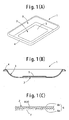
Fig. 1 (C) show an embodiment of wooden container according to the present invention;Fig. 1 (A) is a perspective view of the container,Fig. 1 (B) is a longitudinal sectional view thereof, andFig. 1 (C) is an enlarged sectional view showing a broken part of plywood sheet. - Fig. 2
- (A) to
Fig. 2 (D) show a process of producing wooden sheets for manufacturing wooden containers according to the present invention:Fig. 2 (A) is an explanatory view showing a slicing step of superior sheets,Fig. 2 (B) is an explanatory view showing a slicing step of inferior sheets,Fig. 2 (C) is an explanatory view showing an expansion step of the sheets, andFig. 2 (D) is an explanatory view showing a drying step of the sheets. - Fig. 3
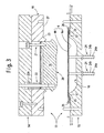
- is a sectional view showing an embodiment of press apparatus.
- Fig. 4
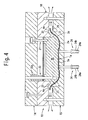
- is a sectional view showing the press apparatus wherein a first forming step to form an intermediate product is carried out.
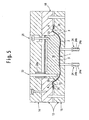
- Fig. 5
- is a sectional view showing the press apparatus wherein a second forming step to form a finished product is carried out.
- Fig. 6(A)
- and
Fig. 6 (B) are enlarged sectional views of the press apparatus in which an adjusting plate is used;Fig. 6 (A) shows a forming step wherein a thin adjusting plate is used, andFig. 6 (B) shows a forming step wherein a thick adjusting plate is used. - Embodiments of the present invention are described in detail by referring to drawings.
- In
Fig. 1 , awooden container 1 is illustrated as a tray, for example, having abottom wall 2 and aperipheral wall 3, the tray may be shaped in either shallow or deep configuration. The tray has asurrounding edge 4 extending outside along an upper opening edge of theperipheral wall 3 and also extending downward as circular in cross section. Abulge portion 5 may be formed by slightly lifting the center ofbottom wall 2 so that moisture of wet food packed in the container may stagnate below the circumference of thebulge portion 5. - The
wooden container 1 is formed by aplywood sheet 6 comprising aninferior sheet 6a having spoiled portions such as knot or crack and asuperior sheet 6b having no such spoiled portion. Theinferior sheet 6a and thesuperior sheet 6b are chosen from a large number of wooden sheets obtained by slicing a wooden piece. Theplywood sheet 6 lays theinferior sheet 6a and thesuperior sheet 6b with each other, then theplywood sheet 6 is heated and pressed by up-and-down dies. Thesheets container 1 as mentioned above. - Accordingly, the whole part of
container 1 is made wooden that can be incinerated easily so that no problem of waste treatment may be caused. Since thewooden container 1 is superior in hygroscopicity etc., it is suitable for packing fresh wet food. - As shown in
Fig. 1 (B) and Fig. 1 (C) , thewooden container 1 is constructed such that an inner wall is formed with saidsuperior sheet 6b and an outside wall is formed with saidinferior sheet 6a. - As illustrated in
Fig. 1 (C) , theinferior sheet 6a includes spoiledportions 7 such as knots and cracks or the like. However, no trouble for packing function of the container is caused, since theinferior sheet 6a is located in outside wall of the container. - On the other hand, the inside of container is formed with the
superior sheet 6b having no spoiled portion, and moisture of fresh food packed in the container does not leak outside.
Theinferior sheet 6a and thesuperior sheet 6b, which constitute theplywood sheet 6, provide respective opposite sides with smooth surfaces but provide respective contact sides withrough surfaces 8 as shown inFig. 1 (C) . Adhesion is carried out byadhesion film 9 formed between the contactedrough surfaces 8. Theadhesion film 9 is made by lignin oozed from wood content to therough surfaces 8 during a heating pressing process as mentioned later. - As shown in
Fig. 2 (A) , manysuperior sheets 6b are formed by slicing a good-qualitywooden piece 10b. The slicedsuperior sheet 6b is formed one side with a smooth surface and another side with a fluffy rough surface. A slice direction of thewood piece 10b is set up so that grain may appear in the surface ofsuperior sheet 6b beautiful. - In the present invention, even low-
quality wood 10a containingspoiled portions 7, such as knot or crack, is used effectively without being discarded. That is, as shown inFig. 2 (B) , manyinferior sheets 6a are formed by slicing a low-qualitywooden piece 10a. The slicedinferior sheet 6a is formed one side with a smooth surface and another side with a fluffy rough surface. A slice direction of thewood piece 10a is set up so that grain may appear in the surface ofinferior sheet 6a beautiful. - The
inferior sheet 6a and thesuperior sheet 6b may be distorted to an arch shape due to rotating cutters of slicing device. The distortion is corrected by inserting thesheets expansion device 11, as shown inFig. 2 (C) . - Subsequently, the
sheets Fig. 2 (D) . - Under the condition that moisture contained in natural wood is considered as 100%, the
sheets sheets sheets sheets - A pair of
inferior sheet 6a andsuperior sheet 6b is chosen from a large number of sheets obtained as mentioned above. Thesheets rough surfaces 8 mutually to provide aplywood sheet 6. - The
plywood sheet 6 is heated and pressed by apress apparatus 13 as shown inFig. 3 to produce an intermediate processed container product 1a (seeFig. 4 ). - When skipping the above mentioned drying step, or even when performing such drying step, powder of starch may be applied by sprinkling, if needed, on at least one of the
rough surfaces 8 of theinferior sheet 6a and thesuperior sheet 6b. The powder may comprise flour for example, and a small quantity is sufficient for the application amount. - The
press apparatus 13 forms, as a first forming step, an intermediate processed container product 1a (herein called as "intermediate product") which is provided with abottom wall 2a and a peripheral wall 3a as shown inFig. 4 . However, anedge portion 4a is extended upwardly from the peripheral wall 3a. The center part ofbottom wall 2a is slightly lifted to provide abulge portion 5a preferably. - As shown in
Fig. 3 , thepress apparatus 13 comprises amale die 14 shown as an upper die, and afemale die 15 shown as a lower die. A driving source (not shown) is provided to open and close both dies 14 and 15. - The female die 15 has a concave 16 in a shape corresponding to the outside of said intermediate product 1a, i.e., corresponding to the outside of the
bottom wall 2a including thebulge portion 5a and the peripheral wall 3a. Anannular projection 17 is formed with the female die 15 at an opening edge of the concave 16. Theannular projection 17 is in an arch-shape in cross section and extends outwardly from the concave 16. - The male die 14 comprises a
main die 18 and a movingdie 19. The movingdie 19 is movable in forward and backward directions towards the female die 15 and is provided with a convex 20 in a shape corresponding to the inside of said intermediate product 1a, i.e., corresponding to the inside of thebottom wall 2a including thebulge portion 5a and the peripheral wall 3a. - The moving
die 19 is guided by guide means 21 to move in forward and backward directions and is usually pushed by pushingmeans 22 having aspring 22a so that the moving die 19 projects from themain die 18. - For manufacturing the intermediate product 1a, the convex 20 of the moving die 19 forms the
bottom wall 2a and the peripheral wall 3a at the same time, however, saidedge portion 4a is not pressed by the convex 20. - The main die 18 provides an
annular groove 23 of which surface fits in a smooth manner to the peripheral edge of the convex 20 of the movingdie 19 when the movingdie 19 is moved fully backward. - The female die 15 has support means 24 projecting in the concave 16. The support means 24 comprises
rods 24a inserted through the female die 15 and springs 24b pushing therods 24a towards themale die 14. Therods 24a are movable in forward and backward directions and are usually pushed by thesprings 24b to advance into the concave 16 but stop at a position that each end of therods 24a comes at same level of the height of saidannular projection 17. - An adjusting
plate 25 is attached detachably to the female die 15 at the portion surrounding theannular projection 17, and positioning means 26 is provided at outside the adjustingplate 25. As shown inFig. 3 , the positioning means 26 is movable between a position close to the adjustingplate 25 as shown by a solid line inFig. 3 and a position away from the female die 15 as shown by a chain line inFig. 3 . - Exhaust means 27 is provided on opposite faces of the male
main die 18 and thefemale die 15. The exhaust means 27 is illustrated as being provided on the opposite faces, however, it may be formed by slot passages provided on at least one of the opposite faces, or by bore passages provided through at least one of the male and female dies. - As shown in
Fig. 3 , under the state that thepress apparatus 13 is opened, theplywood sheet 6 is inserted between the up-and-down dies 14, 15 in such manner that thesuperior sheet 6b faces the male die 14 and theinferior sheet 6a faces thefemale die 15. As for the twosheets plywood sheet 6, it is preferred to make the grains cross mutually. - When the
plywood sheet 6 is put on theannular projection 17 of thefemale die 15, the positioning means 26 is positioned close to theprojection 17 so that the periphery of thesheet 6 is restrained to be positioned at the predetermined position with respect to thefemale die 15. The center region ofplywood sheet 6 is supported at the undersurface by support means 24, thesheet 6 does not bend downward. - Evacuating the positioning means 26 out of dies, as shown in
Fig. 4 , the dies 14 and 15 are closed and heating pressurization to theplywood sheet 6 is carried out to form the intermediate product 1a. - When the male die 14 and the female die 15 are closed, the
plywood sheet 6 is pressed by the convex 20 of the movingdie 19 towards the concave 16 of thefemale die 15, and theplywood sheet 6 is deformed between the convex 20 and the concave 16, while the movingmold 19 being projected by pushingmeans 22. - As the moving
die 19 gets closer to thefemale die 15, the movingdie 19 is retreated in the main die 18 against thespring 22a of the pushing means 22 while guided by the guide means 21. The convex 20 of the movingdie 19 deforms theplywood sheet 6 and pushes it into the concave 16, while the undersurface of thesheet 6 is supported by therods 24a which retreat from the concave 16 against thespring 24b. - The male die 14 and the female die 15 carry out the first forming step of the
plywood sheet 6 where the dies 14 and 15 are not closed completely but are opened a little as shown inFig. 4 . Theplywood sheet 6 is formed with thebottom wall 2a and the peripheral wall 3a to provide the intermediate product 1a between the concave 16 and the convex 20. The movingdie 19 is pushed by thespring 22a of the pushing means 22 so that theplywood sheet 6 is clamped in the concave 6 and heating pressurization to theplywood sheet 6 is carried out. - In the first forming step, the
annular groove 23 of the malemain die 18 and theannular projection 17 of the female die 15 are apart mutually, therefore theedge portion 4a of the intermediate product 1a is not pressed. Thus, the first forming step forms the intermediate product 1a with only thebottom wall 2a and theperipheral wall 3. It does not cause theplywood sheet 6 any strong stress, and neither distortion nor a crack is produced. - The first forming step is carried out for several seconds, about 2 to 3 seconds for example, and the
plywood sheet 6 is heated and pressed to form the intermediate product 1a. The lignin and moisture in wood content of theplywood sheet 6 become steam and ooze to therough surfaces 8 to glue together. - When powder of starch is applied to one of the rough surfaces as mentioned above, it becomes paste with steam, and it spreads over the
rough surfaces 8 and glues together. - Steam generated during the first forming step is discharged out of the
press apparatus 13 via exhaust means 27. - Subsequently, the
press apparatus 13 is closed until the male die 14 and the female die 15 are brought in a complete clamp state to carry out a second forming step as shown inFig. 5 . Here, heating pressurization is performed again to the intermediate product 1a, and afinished container product 1 is produced. - In the second forming step, the
annular projection 17 of the female die 15 and theannular groove 23 of the malemain die 18 are closed mutually, while the movingdie 19 is retreated in the main die 18 so as to meet the peripheral edge of the convex 20 with theannular groove 23. Theedge portion 4a, which has not been pressed during the first forming step, is now heated and pressed to be shaped in a downward circle shape in cross section, thereby a surroundingedge 4 is formed. - In the second forming step, the intermediate product 1a is clamped again while forming the
surrounding edge 4. Thebottom wall 2a and the peripheral wall 3a are firmly clamped stronger than the clamping operation in the first forming step. Therefore, the plywood comprising thefinished container product 1 is stiffened firmly, and its intensity is improved. In addition, even in case that the intermediate product 1a obtained by the first forming step includes distortion of a twist and the like in thebottom wall 2a or the peripheral wall 3a, such distortion is corrected by the second forming step.
A potential problem may be included in the second forming step that a crack is produced depending on the wood quality, when pressing theedge portion 4a of the intermediate product 1a to form the surroundingedge 4 of thefinished container product 1. Such a crack has the tendency to be easy to generate if the upheaval of surroundingedge 4 becomes remarkable, in other words, the curvature radius of surroundingedge 4 becomes small. - For this reason, the
press apparatus 13 provides the female die 15 with the adjustingplate 25 at outside portion near the periphery ofannular projection 17. It is preferred that plural plates having different thicknesses are prepared to be selectively used, such as afirst adjusting plate 25a of comparatively small thickness T1 (2mm in thickness for example) as shown inFig. 6 (A) , and asecond adjusting plate 25b of comparatively large thickness T2 (3mm in thickness for example). Each adjustingplate 25 forms an annular frame like configuration surrounding the outside ofannular projection 17 and is attached on the female die 15 detachably. - The adjusting
plate 25 may be removed when the second forming step is carried out. In case that no adjusting plate is attached, the surroundingedge 4 formed by theedge portion 4a of the intermediate product 1a becomes highest with respect to its height H. - If it seems that the surrounding
edge 4 breaks in that condition, thefirst adjusting plate 25a of small thickness T1 is attached as shown inFig. 6 (A) , and the second forming step is carried out. Thereby, the problem of causing cracks may be solved since the surroundingedge 4 to be formed by theedge portion 4a is made its height H1 lower than the case where the adjustingplate 25a is not provided. - If it further seems that the surrounding
edge 4 still breaks even thefirst adjusting plate 25a attached, it is replaced with thesecond adjusting plate 25b of large thickness T2 (namely, T2>T1) as shown inFig. 6 (B) , and the second forming step is carried out. The problem of causing cracks will be solved since the surroundingedge 4 to be formed by theedge portion 4a is made its height H2 further lower than the case where thefirst adjusting plate 25a is attached (namely, H2<H1). - Although two or more kinds of adjusting
plates - The foregoing embodiment which performs two steps of the first forming step and the second forming step corresponds to the invention defined in
claim 3. It is not always necessary for the invention to perform two forming steps in accordance with the invention defined inclaim 2.
In case that a wooden container having no surroundingedge 4 is manufactured for example, the container may be formed by pressing aplywood sheet 6 only by one forming step of thepress apparatus 13.
Claims (4)
- A wooden container for packing wet food comprising a bottom wall (2) and a peripheral wall (3) formed by pressing and heating a plywood sheet (6) within up-and-down dies of a press apparatus characterized in that:said plywood sheet (6) comprises an inferior wooden sheet (6a) having at least one spoiled portion (7) such as knots or damages represented by cracks and a superior wooden sheet (6b) having no such spoiled portion, and said superior wooden sheet (6b) forms an inside of the container and said inferior wooden sheet (6a) forms an outside of the container so that said superior wooden sheet (6b) prevents moisture of food packed in the container from leaking outside, andsaid inferior and superior wooden sheets (6a, 6b) are glued mutually by lignin which is oozed from wood content to contacting surfaces of said sheets (6a, 6b) when said plywood sheet (6) is pressed and heated between the up-and-down dies.
- A process for manufacturing a wooden container for packing wet food as defined in claim 1, comprising:a step of providing a large number of wooden sheets by slicing wooden pieces and forming a smooth surface and a fluffy rough surface (8) on respective sides of each wooden sheet;a step of forming a plywood sheet by laying two wooden sheets, anda step of carrying out heating pressurization to said plywood sheet between male and female dies of a press apparatus to form said wooden container, characterized in that:said wooden sheets are dried to reduce moisture in wood content to a limited quantity in advance of forming the plywood sheet (6),said plywood sheet (6) is formed in such manner that a pair of wooden sheets selected, one being an inferior sheet (6a) including at least one spoiled portion (7) such as knots or damages represented by cracks and another one being a superior sheet (6b) including no such spoiled portion, are laid together by contacting the respective fluffy rough surfaces (8) so that an inside of the container is formed by said superior sheet (6b) and an outside of the container is formed by said inferior wooden sheet (6a), andsaid heating pressurization is carried out in such a manner that said moisture of limited quantity oozes together with lignin from wood content to the mutual fluffy rough surfaces (8, 8) so that said rough surfaces are glued by said lignin.
- A process for manufacturing a wooden container for packing wet food according to claim 2, wherein said wooden container forms a surrounding edge (4) extending along an upper edge of the peripheral wall (3) in a shape of circular extending downward in cross section, wherein
said step of carrying out heating pressurization comprises a first forming step and a second forming step wherein:said first forming step produces an intermediate product (1 a) by carrying out heating pressurization to said plywood sheet (6) on its center region except its peripheral region in such a manner that said plywood sheet (6) is formed with a bottom wall (2a) and a peripheral wall (3a) having an edge portion (4a) extending upwardly therefrom, and moisture of limited quantity oozes together with lignin from wood content to the contacted fluffy rough surfaces (8, 8) of the sheets (6a, 6b); andsaid second forming step produces a finished product (1) by carrying out further heating pressurization to said intermediate product (1a) by clamping entire part thereof in such a manner that said edge portion (4a) is formed with said surrounding edge (4) while said bottom and peripheral walls (2a, 3a) are firmly clamped stronger than the clamping operation in the first forming step so that said walls (2a, 3a) are stiffened firmly to improve intensity, thereby the wooden container (1) as the finished product formed with said stiffened bottom and peripheral walls (2, 3) and said surrounding edge (4) is produced. - A process for manufacturing a wooden container for packing wet food according to claim 2 or 3, wherein the moisture in said inferior and superior sheets (6a, 6b) after dried is made into substantially 10% to 20% under the condition that moisture contained in natural wood is made as 100%.
Priority Applications (4)
| Application Number | Priority Date | Filing Date | Title |
|---|---|---|---|
| EP20070016667 EP2028112B1 (en) | 2007-08-24 | 2007-08-24 | A wooden container and a process for manufacturing thereof |
| AT07016667T ATE501039T1 (en) | 2007-08-24 | 2007-08-24 | WOODEN CONTAINER AND PRODUCTION PROCESS THEREOF |
| EP20080002310 EP2050678A1 (en) | 2007-08-24 | 2007-08-24 | Process and apparatus for manufacturing a wooden container |
| DE200760013037 DE602007013037D1 (en) | 2007-08-24 | 2007-08-24 | Wooden container and manufacturing process for it |
Applications Claiming Priority (1)
| Application Number | Priority Date | Filing Date | Title |
|---|---|---|---|
| EP20070016667 EP2028112B1 (en) | 2007-08-24 | 2007-08-24 | A wooden container and a process for manufacturing thereof |
Related Child Applications (3)
| Application Number | Title | Priority Date | Filing Date |
|---|---|---|---|
| EP20080002310 Division-Into EP2050678A1 (en) | 2007-08-24 | 2007-08-24 | Process and apparatus for manufacturing a wooden container |
| EP20080002310 Division EP2050678A1 (en) | 2007-08-24 | 2007-08-24 | Process and apparatus for manufacturing a wooden container |
| EP08002310.4 Division-Into | 2008-02-07 |
Publications (2)
| Publication Number | Publication Date |
|---|---|
| EP2028112A1 EP2028112A1 (en) | 2009-02-25 |
| EP2028112B1 true EP2028112B1 (en) | 2011-03-09 |
Family
ID=38841228
Family Applications (2)
| Application Number | Title | Priority Date | Filing Date |
|---|---|---|---|
| EP20080002310 Withdrawn EP2050678A1 (en) | 2007-08-24 | 2007-08-24 | Process and apparatus for manufacturing a wooden container |
| EP20070016667 Not-in-force EP2028112B1 (en) | 2007-08-24 | 2007-08-24 | A wooden container and a process for manufacturing thereof |
Family Applications Before (1)
| Application Number | Title | Priority Date | Filing Date |
|---|---|---|---|
| EP20080002310 Withdrawn EP2050678A1 (en) | 2007-08-24 | 2007-08-24 | Process and apparatus for manufacturing a wooden container |
Country Status (3)
| Country | Link |
|---|---|
| EP (2) | EP2050678A1 (en) |
| AT (1) | ATE501039T1 (en) |
| DE (1) | DE602007013037D1 (en) |
Families Citing this family (3)
| Publication number | Priority date | Publication date | Assignee | Title |
|---|---|---|---|---|
| CN102922582A (en) * | 2012-06-18 | 2013-02-13 | 徐飞 | Manufacturing method of container |
| JP6086521B2 (en) * | 2012-07-17 | 2017-03-01 | 株式会社パームホルツ | Oil palm sheet joining composition and joining method thereof |
| EP2832508B1 (en) * | 2013-07-29 | 2018-10-24 | Faurecia Innenraum Systeme GmbH | Method for forming a trim element having a layer of ligneous material with a three-dimensional shape |
Family Cites Families (20)
| Publication number | Priority date | Publication date | Assignee | Title |
|---|---|---|---|---|
| GB218634A (en) | 1923-07-03 | 1925-09-07 | Ago Mij | Method and means for making pressed articles from wood |
| DE430121C (en) * | 1924-09-04 | 1926-06-09 | Schmidt Karl | Process for the production of curved walls for furniture and other objects from thick plywood panels |
| DE819812C (en) * | 1949-12-13 | 1951-11-05 | Georg Biller | barrel |
| DE819821C (en) | 1950-04-22 | 1951-11-05 | Buettner Werke A G | Vertical dryer, especially for the dry treatment of water-rich products |
| DE1026947B (en) | 1954-12-04 | 1958-03-27 | Hubert Clompe | Method and device for the production of clock case shells and similarly shaped walls or bodies from plywood |
| FR1500105A (en) | 1966-07-06 | 1967-11-03 | Doc Emballages | Process for obtaining deep stamps in plywood and products obtained by this process |
| JPS5217271A (en) | 1975-07-31 | 1977-02-09 | Iwai Tsusho Kk | Molding device of paper made container |
| IT1144942B (en) * | 1981-11-18 | 1986-10-29 | Alberto Piaggi | PROCEDURE FOR THE MANUFACTURE OF SPECIFIC PRODUCTS FOR THE STORAGE, TRANSPORT, PREPARATION AND CONSUMPTION OF FOOD AND BEVERAGES AND RESPECTIVE PRODUCTS OBTAINED BY SUCH PROCEDURES, SUCH AS EXAMPLES, FLAT PLATES AND BOTTLES, CUPS AND CUPS, GLASSES, AND SIMILAR |
| US5040582A (en) | 1990-06-22 | 1991-08-20 | Forintek Canada Corp. | Multi species laminated veneer lumber |
| JPH0999412A (en) * | 1995-10-04 | 1997-04-15 | Taikoo Rinzai:Kk | Manufacture of wooden tray |
| JPH09169328A (en) | 1995-12-15 | 1997-06-30 | Tachibana Shokai:Kk | Tray and production method thereof |
| JPH106308A (en) * | 1996-06-25 | 1998-01-13 | Nippon Esuko Kk | Preparation of container for packaging |
| JP2001030207A (en) * | 1999-07-19 | 2001-02-06 | Hideyo Honda | Manufacture of bamboo sheath container |
| JP2002137203A (en) * | 2000-11-01 | 2002-05-14 | Akira Matsumoto | Bamboo sheath product |
| JP2003054531A (en) | 2001-08-09 | 2003-02-26 | Yanagi Products Kk | Food container and method for manufacturing the same |
| JP3972213B2 (en) * | 2002-06-11 | 2007-09-05 | 宮崎県 | Manufacturing method of wooden deep bottom container |
| DE102004035758C5 (en) * | 2004-07-23 | 2011-08-18 | Quin GmbH, 71277 | Method and device for producing a decorative preform |
| CN100460289C (en) * | 2005-08-25 | 2009-02-11 | 泓齐科技有限公司 | Wooden container and its making method |
| JP2007238171A (en) * | 2006-03-03 | 2007-09-20 | Blue Star:Kk | Molding die for wooden veneer and wooden laminate |
| JP4274573B2 (en) * | 2006-03-24 | 2009-06-10 | 株式会社森林資源利用促進研究所 | Wooden container and manufacturing method thereof |
-
2007
- 2007-08-24 AT AT07016667T patent/ATE501039T1/en not_active IP Right Cessation
- 2007-08-24 DE DE200760013037 patent/DE602007013037D1/en active Active
- 2007-08-24 EP EP20080002310 patent/EP2050678A1/en not_active Withdrawn
- 2007-08-24 EP EP20070016667 patent/EP2028112B1/en not_active Not-in-force
Also Published As
| Publication number | Publication date |
|---|---|
| EP2028112A1 (en) | 2009-02-25 |
| DE602007013037D1 (en) | 2011-04-21 |
| ATE501039T1 (en) | 2011-03-15 |
| EP2050678A1 (en) | 2009-04-22 |
Similar Documents
| Publication | Publication Date | Title |
|---|---|---|
| US20070221625A1 (en) | Wooden container and a process for manufacturing thereof | |
| US8079390B2 (en) | Process of production of disposable wooden cutlery and product thereof | |
| US7131471B2 (en) | Compressed wood product and manufacture | |
| US20070220720A1 (en) | Casket lid and method of making same | |
| EP2028112B1 (en) | A wooden container and a process for manufacturing thereof | |
| WO2008018784A1 (en) | A method to manufacture plywood | |
| US7963311B2 (en) | Veneer lay-up squeezing | |
| KR20180069759A (en) | woodstraw manufacturing method | |
| CA1079560A (en) | Method and a machine for producing cellular latticework | |
| CN201597084U (en) | Novel solid wood plywood | |
| US20120282423A1 (en) | Joined Veneer Strip | |
| CA2256521A1 (en) | Process and press for manufacturing glued blocks | |
| EP3489004A1 (en) | Packaging plywood sleeve | |
| CN109623972B (en) | Wood veneer decorative stone-plastic substrate and production process thereof | |
| CN102554999B (en) | Wooden veneer container and for manufacturing its method and hot-press equipment | |
| US343439A (en) | Half to robert b | |
| EP1634691A1 (en) | Machine for lining paper or plastic packages | |
| CN107297794A (en) | The production technology of glued board | |
| CA2421016C (en) | Casket lid and method of making same | |
| KR20050018779A (en) | Manufacturing method board for a coffin and board for a coffin of wrapping structure seat | |
| JP2008168637A (en) | Method and apparatus for manufacturing wooden container | |
| FR2496052A1 (en) | METHOD AND DEVICE FOR MANUFACTURING A PRESENTATION BOX AND BOX THUS OBTAINED | |
| KR20040067275A (en) | The method and the apparatus of inlaying the wood surface with wooden sheet | |
| CN101332615A (en) | Cotton-wood artificial basis material veneer anti-wracking technique | |
| FR2498974A1 (en) | PROCESS FOR THE PRODUCTION OF MOLDED WOOD PANELS AND WOOD SUBSTITUTES FOR FURNITURE DOORS |
Legal Events
| Date | Code | Title | Description |
|---|---|---|---|
| PUAI | Public reference made under article 153(3) epc to a published international application that has entered the european phase |
Free format text: ORIGINAL CODE: 0009012 |
|
| 17P | Request for examination filed |
Effective date: 20070921 |
|
| AK | Designated contracting states |
Kind code of ref document: A1 Designated state(s): AT BE BG CH CY CZ DE DK EE ES FI FR GB GR HU IE IS IT LI LT LU LV MC MT NL PL PT RO SE SI SK TR |
|
| AX | Request for extension of the european patent |
Extension state: AL BA HR MK RS |
|
| AKX | Designation fees paid |
Designated state(s): AT BE BG CH CY CZ DE DK EE ES FI FR GB GR HU IE IS IT LI LT LU LV MC MT NL PL PT RO SE SI SK TR |
|
| GRAP | Despatch of communication of intention to grant a patent |
Free format text: ORIGINAL CODE: EPIDOSNIGR1 |
|
| GRAS | Grant fee paid |
Free format text: ORIGINAL CODE: EPIDOSNIGR3 |
|
| GRAA | (expected) grant |
Free format text: ORIGINAL CODE: 0009210 |
|
| AK | Designated contracting states |
Kind code of ref document: B1 Designated state(s): AT BE BG CH CY CZ DE DK EE ES FI FR GB GR HU IE IS IT LI LT LU LV MC MT NL PL PT RO SE SI SK TR |
|
| REG | Reference to a national code |
Ref country code: GB Ref legal event code: FG4D |
|
| REG | Reference to a national code |
Ref country code: CH Ref legal event code: EP |
|
| REG | Reference to a national code |
Ref country code: IE Ref legal event code: FG4D |
|
| REF | Corresponds to: |
Ref document number: 602007013037 Country of ref document: DE Date of ref document: 20110421 Kind code of ref document: P |
|
| REG | Reference to a national code |
Ref country code: DE Ref legal event code: R096 Ref document number: 602007013037 Country of ref document: DE Effective date: 20110421 |
|
| REG | Reference to a national code |
Ref country code: NL Ref legal event code: VDEP Effective date: 20110309 |
|
| PG25 | Lapsed in a contracting state [announced via postgrant information from national office to epo] |
Ref country code: LV Free format text: LAPSE BECAUSE OF FAILURE TO SUBMIT A TRANSLATION OF THE DESCRIPTION OR TO PAY THE FEE WITHIN THE PRESCRIBED TIME-LIMIT Effective date: 20110309 Ref country code: LT Free format text: LAPSE BECAUSE OF FAILURE TO SUBMIT A TRANSLATION OF THE DESCRIPTION OR TO PAY THE FEE WITHIN THE PRESCRIBED TIME-LIMIT Effective date: 20110309 Ref country code: GR Free format text: LAPSE BECAUSE OF FAILURE TO SUBMIT A TRANSLATION OF THE DESCRIPTION OR TO PAY THE FEE WITHIN THE PRESCRIBED TIME-LIMIT Effective date: 20110610 Ref country code: SE Free format text: LAPSE BECAUSE OF FAILURE TO SUBMIT A TRANSLATION OF THE DESCRIPTION OR TO PAY THE FEE WITHIN THE PRESCRIBED TIME-LIMIT Effective date: 20110309 Ref country code: ES Free format text: LAPSE BECAUSE OF FAILURE TO SUBMIT A TRANSLATION OF THE DESCRIPTION OR TO PAY THE FEE WITHIN THE PRESCRIBED TIME-LIMIT Effective date: 20110620 |
|
| LTIE | Lt: invalidation of european patent or patent extension |
Effective date: 20110309 |
|
| PG25 | Lapsed in a contracting state [announced via postgrant information from national office to epo] |
Ref country code: FI Free format text: LAPSE BECAUSE OF FAILURE TO SUBMIT A TRANSLATION OF THE DESCRIPTION OR TO PAY THE FEE WITHIN THE PRESCRIBED TIME-LIMIT Effective date: 20110309 Ref country code: NL Free format text: LAPSE BECAUSE OF FAILURE TO SUBMIT A TRANSLATION OF THE DESCRIPTION OR TO PAY THE FEE WITHIN THE PRESCRIBED TIME-LIMIT Effective date: 20110309 Ref country code: BG Free format text: LAPSE BECAUSE OF FAILURE TO SUBMIT A TRANSLATION OF THE DESCRIPTION OR TO PAY THE FEE WITHIN THE PRESCRIBED TIME-LIMIT Effective date: 20110609 Ref country code: SI Free format text: LAPSE BECAUSE OF FAILURE TO SUBMIT A TRANSLATION OF THE DESCRIPTION OR TO PAY THE FEE WITHIN THE PRESCRIBED TIME-LIMIT Effective date: 20110309 Ref country code: AT Free format text: LAPSE BECAUSE OF FAILURE TO SUBMIT A TRANSLATION OF THE DESCRIPTION OR TO PAY THE FEE WITHIN THE PRESCRIBED TIME-LIMIT Effective date: 20110309 Ref country code: CY Free format text: LAPSE BECAUSE OF FAILURE TO SUBMIT A TRANSLATION OF THE DESCRIPTION OR TO PAY THE FEE WITHIN THE PRESCRIBED TIME-LIMIT Effective date: 20110309 |
|
| PG25 | Lapsed in a contracting state [announced via postgrant information from national office to epo] |
Ref country code: BE Free format text: LAPSE BECAUSE OF FAILURE TO SUBMIT A TRANSLATION OF THE DESCRIPTION OR TO PAY THE FEE WITHIN THE PRESCRIBED TIME-LIMIT Effective date: 20110309 |
|
| PG25 | Lapsed in a contracting state [announced via postgrant information from national office to epo] |
Ref country code: PT Free format text: LAPSE BECAUSE OF FAILURE TO SUBMIT A TRANSLATION OF THE DESCRIPTION OR TO PAY THE FEE WITHIN THE PRESCRIBED TIME-LIMIT Effective date: 20110711 Ref country code: EE Free format text: LAPSE BECAUSE OF FAILURE TO SUBMIT A TRANSLATION OF THE DESCRIPTION OR TO PAY THE FEE WITHIN THE PRESCRIBED TIME-LIMIT Effective date: 20110309 |
|
| PG25 | Lapsed in a contracting state [announced via postgrant information from national office to epo] |
Ref country code: SK Free format text: LAPSE BECAUSE OF FAILURE TO SUBMIT A TRANSLATION OF THE DESCRIPTION OR TO PAY THE FEE WITHIN THE PRESCRIBED TIME-LIMIT Effective date: 20110309 Ref country code: CZ Free format text: LAPSE BECAUSE OF FAILURE TO SUBMIT A TRANSLATION OF THE DESCRIPTION OR TO PAY THE FEE WITHIN THE PRESCRIBED TIME-LIMIT Effective date: 20110309 Ref country code: IS Free format text: LAPSE BECAUSE OF FAILURE TO SUBMIT A TRANSLATION OF THE DESCRIPTION OR TO PAY THE FEE WITHIN THE PRESCRIBED TIME-LIMIT Effective date: 20110709 Ref country code: RO Free format text: LAPSE BECAUSE OF FAILURE TO SUBMIT A TRANSLATION OF THE DESCRIPTION OR TO PAY THE FEE WITHIN THE PRESCRIBED TIME-LIMIT Effective date: 20110309 |
|
| PGFP | Annual fee paid to national office [announced via postgrant information from national office to epo] |
Ref country code: DE Payment date: 20110822 Year of fee payment: 5 Ref country code: FR Payment date: 20110829 Year of fee payment: 5 Ref country code: GB Payment date: 20110824 Year of fee payment: 5 |
|
| PG25 | Lapsed in a contracting state [announced via postgrant information from national office to epo] |
Ref country code: MT Free format text: LAPSE BECAUSE OF FAILURE TO SUBMIT A TRANSLATION OF THE DESCRIPTION OR TO PAY THE FEE WITHIN THE PRESCRIBED TIME-LIMIT Effective date: 20110309 |
|
| PGFP | Annual fee paid to national office [announced via postgrant information from national office to epo] |
Ref country code: IT Payment date: 20110825 Year of fee payment: 5 |
|
| PLBE | No opposition filed within time limit |
Free format text: ORIGINAL CODE: 0009261 |
|
| STAA | Information on the status of an ep patent application or granted ep patent |
Free format text: STATUS: NO OPPOSITION FILED WITHIN TIME LIMIT |
|
| 26N | No opposition filed |
Effective date: 20111212 |
|
| PG25 | Lapsed in a contracting state [announced via postgrant information from national office to epo] |
Ref country code: PL Free format text: LAPSE BECAUSE OF FAILURE TO SUBMIT A TRANSLATION OF THE DESCRIPTION OR TO PAY THE FEE WITHIN THE PRESCRIBED TIME-LIMIT Effective date: 20110309 Ref country code: DK Free format text: LAPSE BECAUSE OF FAILURE TO SUBMIT A TRANSLATION OF THE DESCRIPTION OR TO PAY THE FEE WITHIN THE PRESCRIBED TIME-LIMIT Effective date: 20110309 |
|
| PG25 | Lapsed in a contracting state [announced via postgrant information from national office to epo] |
Ref country code: MC Free format text: LAPSE BECAUSE OF NON-PAYMENT OF DUE FEES Effective date: 20110831 |
|
| REG | Reference to a national code |
Ref country code: CH Ref legal event code: PL |
|
| REG | Reference to a national code |
Ref country code: DE Ref legal event code: R097 Ref document number: 602007013037 Country of ref document: DE Effective date: 20111212 |
|
| PG25 | Lapsed in a contracting state [announced via postgrant information from national office to epo] |
Ref country code: CH Free format text: LAPSE BECAUSE OF NON-PAYMENT OF DUE FEES Effective date: 20110831 Ref country code: LI Free format text: LAPSE BECAUSE OF NON-PAYMENT OF DUE FEES Effective date: 20110831 |
|
| REG | Reference to a national code |
Ref country code: IE Ref legal event code: MM4A |
|
| PG25 | Lapsed in a contracting state [announced via postgrant information from national office to epo] |
Ref country code: IE Free format text: LAPSE BECAUSE OF NON-PAYMENT OF DUE FEES Effective date: 20110824 |
|
| GBPC | Gb: european patent ceased through non-payment of renewal fee |
Effective date: 20120824 |
|
| REG | Reference to a national code |
Ref country code: FR Ref legal event code: ST Effective date: 20130430 |
|
| PG25 | Lapsed in a contracting state [announced via postgrant information from national office to epo] |
Ref country code: LU Free format text: LAPSE BECAUSE OF NON-PAYMENT OF DUE FEES Effective date: 20110824 Ref country code: IT Free format text: LAPSE BECAUSE OF NON-PAYMENT OF DUE FEES Effective date: 20120824 |
|
| PG25 | Lapsed in a contracting state [announced via postgrant information from national office to epo] |
Ref country code: DE Free format text: LAPSE BECAUSE OF NON-PAYMENT OF DUE FEES Effective date: 20130301 Ref country code: GB Free format text: LAPSE BECAUSE OF NON-PAYMENT OF DUE FEES Effective date: 20120824 |
|
| PG25 | Lapsed in a contracting state [announced via postgrant information from national office to epo] |
Ref country code: FR Free format text: LAPSE BECAUSE OF NON-PAYMENT OF DUE FEES Effective date: 20120831 |
|
| REG | Reference to a national code |
Ref country code: DE Ref legal event code: R119 Ref document number: 602007013037 Country of ref document: DE Effective date: 20130301 |
|
| PG25 | Lapsed in a contracting state [announced via postgrant information from national office to epo] |
Ref country code: TR Free format text: LAPSE BECAUSE OF FAILURE TO SUBMIT A TRANSLATION OF THE DESCRIPTION OR TO PAY THE FEE WITHIN THE PRESCRIBED TIME-LIMIT Effective date: 20110309 |
|
| PG25 | Lapsed in a contracting state [announced via postgrant information from national office to epo] |
Ref country code: HU Free format text: LAPSE BECAUSE OF FAILURE TO SUBMIT A TRANSLATION OF THE DESCRIPTION OR TO PAY THE FEE WITHIN THE PRESCRIBED TIME-LIMIT Effective date: 20110309 |