EP2026456A1 - Onduleur - Google Patents
Onduleur Download PDFInfo
- Publication number
- EP2026456A1 EP2026456A1 EP08012566A EP08012566A EP2026456A1 EP 2026456 A1 EP2026456 A1 EP 2026456A1 EP 08012566 A EP08012566 A EP 08012566A EP 08012566 A EP08012566 A EP 08012566A EP 2026456 A1 EP2026456 A1 EP 2026456A1
- Authority
- EP
- European Patent Office
- Prior art keywords
- switches
- intermediate circuit
- voltage
- series
- inverter
- Prior art date
- Legal status (The legal status is an assumption and is not a legal conclusion. Google has not performed a legal analysis and makes no representation as to the accuracy of the status listed.)
- Withdrawn
Links
Images


Classifications
-
- H—ELECTRICITY
- H02—GENERATION; CONVERSION OR DISTRIBUTION OF ELECTRIC POWER
- H02M—APPARATUS FOR CONVERSION BETWEEN AC AND AC, BETWEEN AC AND DC, OR BETWEEN DC AND DC, AND FOR USE WITH MAINS OR SIMILAR POWER SUPPLY SYSTEMS; CONVERSION OF DC OR AC INPUT POWER INTO SURGE OUTPUT POWER; CONTROL OR REGULATION THEREOF
- H02M7/00—Conversion of ac power input into dc power output; Conversion of dc power input into ac power output
- H02M7/42—Conversion of dc power input into ac power output without possibility of reversal
- H02M7/44—Conversion of dc power input into ac power output without possibility of reversal by static converters
- H02M7/48—Conversion of dc power input into ac power output without possibility of reversal by static converters using discharge tubes with control electrode or semiconductor devices with control electrode
- H02M7/53—Conversion of dc power input into ac power output without possibility of reversal by static converters using discharge tubes with control electrode or semiconductor devices with control electrode using devices of a triode or transistor type requiring continuous application of a control signal
- H02M7/537—Conversion of dc power input into ac power output without possibility of reversal by static converters using discharge tubes with control electrode or semiconductor devices with control electrode using devices of a triode or transistor type requiring continuous application of a control signal using semiconductor devices only, e.g. single switched pulse inverters
- H02M7/5387—Conversion of dc power input into ac power output without possibility of reversal by static converters using discharge tubes with control electrode or semiconductor devices with control electrode using devices of a triode or transistor type requiring continuous application of a control signal using semiconductor devices only, e.g. single switched pulse inverters in a bridge configuration
-
- H—ELECTRICITY
- H02—GENERATION; CONVERSION OR DISTRIBUTION OF ELECTRIC POWER
- H02M—APPARATUS FOR CONVERSION BETWEEN AC AND AC, BETWEEN AC AND DC, OR BETWEEN DC AND DC, AND FOR USE WITH MAINS OR SIMILAR POWER SUPPLY SYSTEMS; CONVERSION OF DC OR AC INPUT POWER INTO SURGE OUTPUT POWER; CONTROL OR REGULATION THEREOF
- H02M7/00—Conversion of ac power input into dc power output; Conversion of dc power input into ac power output
- H02M7/42—Conversion of dc power input into ac power output without possibility of reversal
- H02M7/44—Conversion of dc power input into ac power output without possibility of reversal by static converters
- H02M7/48—Conversion of dc power input into ac power output without possibility of reversal by static converters using discharge tubes with control electrode or semiconductor devices with control electrode
- H02M7/505—Conversion of dc power input into ac power output without possibility of reversal by static converters using discharge tubes with control electrode or semiconductor devices with control electrode using devices of a thyratron or thyristor type requiring extinguishing means
- H02M7/515—Conversion of dc power input into ac power output without possibility of reversal by static converters using discharge tubes with control electrode or semiconductor devices with control electrode using devices of a thyratron or thyristor type requiring extinguishing means using semiconductor devices only
- H02M7/521—Conversion of dc power input into ac power output without possibility of reversal by static converters using discharge tubes with control electrode or semiconductor devices with control electrode using devices of a thyratron or thyristor type requiring extinguishing means using semiconductor devices only in a bridge configuration
-
- H—ELECTRICITY
- H02—GENERATION; CONVERSION OR DISTRIBUTION OF ELECTRIC POWER
- H02M—APPARATUS FOR CONVERSION BETWEEN AC AND AC, BETWEEN AC AND DC, OR BETWEEN DC AND DC, AND FOR USE WITH MAINS OR SIMILAR POWER SUPPLY SYSTEMS; CONVERSION OF DC OR AC INPUT POWER INTO SURGE OUTPUT POWER; CONTROL OR REGULATION THEREOF
- H02M3/00—Conversion of dc power input into dc power output
- H02M3/02—Conversion of dc power input into dc power output without intermediate conversion into ac
- H02M3/04—Conversion of dc power input into dc power output without intermediate conversion into ac by static converters
- H02M3/10—Conversion of dc power input into dc power output without intermediate conversion into ac by static converters using discharge tubes with control electrode or semiconductor devices with control electrode
- H02M3/145—Conversion of dc power input into dc power output without intermediate conversion into ac by static converters using discharge tubes with control electrode or semiconductor devices with control electrode using devices of a triode or transistor type requiring continuous application of a control signal
- H02M3/155—Conversion of dc power input into dc power output without intermediate conversion into ac by static converters using discharge tubes with control electrode or semiconductor devices with control electrode using devices of a triode or transistor type requiring continuous application of a control signal using semiconductor devices only
- H02M3/156—Conversion of dc power input into dc power output without intermediate conversion into ac by static converters using discharge tubes with control electrode or semiconductor devices with control electrode using devices of a triode or transistor type requiring continuous application of a control signal using semiconductor devices only with automatic control of output voltage or current, e.g. switching regulators
- H02M3/158—Conversion of dc power input into dc power output without intermediate conversion into ac by static converters using discharge tubes with control electrode or semiconductor devices with control electrode using devices of a triode or transistor type requiring continuous application of a control signal using semiconductor devices only with automatic control of output voltage or current, e.g. switching regulators including plural semiconductor devices as final control devices for a single load
-
- H—ELECTRICITY
- H02—GENERATION; CONVERSION OR DISTRIBUTION OF ELECTRIC POWER
- H02M—APPARATUS FOR CONVERSION BETWEEN AC AND AC, BETWEEN AC AND DC, OR BETWEEN DC AND DC, AND FOR USE WITH MAINS OR SIMILAR POWER SUPPLY SYSTEMS; CONVERSION OF DC OR AC INPUT POWER INTO SURGE OUTPUT POWER; CONTROL OR REGULATION THEREOF
- H02M7/00—Conversion of ac power input into dc power output; Conversion of dc power input into ac power output
- H02M7/42—Conversion of dc power input into ac power output without possibility of reversal
- H02M7/44—Conversion of dc power input into ac power output without possibility of reversal by static converters
- H02M7/48—Conversion of dc power input into ac power output without possibility of reversal by static converters using discharge tubes with control electrode or semiconductor devices with control electrode
Definitions
- the invention relates to an inverter of the type specified in the preamble of claim 1.
- DC generators For feeding electrical energy with DC generators such.
- B. photovoltaic or fuel cell systems is generated, in an AC network, in particular the public power grid (50/60 Hz), inverters of various kinds are used. Between the DC generator and the inverter is in In most cases, a DC-DC converter (DC / DC controller) is provided, which serves the purpose of converting the DC voltage supplied by the DC voltage generator into a DC voltage required by or adapted to the inverter.
- DC / DC controller DC / DC controller
- transformers In principle, leakage currents of the type described can be readily avoided if DC-DC converters with transformers are used which bring about galvanic isolation of the DC voltage side from the AC voltage side.
- transformers regardless of whether mains transformers or high-frequency transformers are used, transformers have, inter alia, a reduction of the efficiency, in some cases considerable weights and sizes and / or an additional control effort, which is why transformerless voltage transformers are preferred.
- transformerless DC wall transformers either make the desired grounding impossible, as this would result in the shorting of required switches, capacitors, or the like, or result in increased circuit complexity and other disadvantages.
- circuits which serve the purpose of reducing the unwanted leakage currents (eg. DE 10 2004 037 466 A1 . DE 102 21 592 A1 . DE 10 2004 030 912 B3 ).
- DE 10 2004 037 466 A1 . DE 102 21 592 A1 . DE 10 2004 030 912 B3 operated a solar generator in certain phases of the internal electric energy transport isolated from the grid.
- parasitic capacitances are only slightly transhipped, so that the potential of the solar generator with power frequency, sinusoidal and at a voltage amplitude corresponding to half the mains voltage changes.
- High-frequency currents are then formed by the low voltage differences of the solar generator only between two switching cycles and by asymmetries during switching off.
- circuit arrangements are already known with which a solar generator can be grounded on one side despite the absence of a transformer. As a result, capacitive leakage currents are inherently prevented.
- One of these circuit arrangements ( DE 196 42 522 C1 ), however, requires five active switches, with one or two switches simultaneously switching to high-frequency and providing the average output current. In this circuit, also referred to as "flying inductor", the efficiency is therefore impaired by the high number of components involved in the current flow simultaneously in series.
- a disadvantage of this circuit also that lückende current pulses are impressed into the network, which make a capacitive line filter required that degrades the inherent by its own reactive power demand the power factor, but also the efficiency of the circuit in the partial load range.
- inverters are bipolar Voltage supply circuit provided, which includes two series-connected capacitors, which are connected to one of the neutral and neutral conductor of the respective network and connected to this ground terminal with each other.
- the ground connection of the inverter can also be connected to the negative output of the DC voltage generator. This is made possible by using a special storage choke, which is composed of two magnetically coupled windings.
- this device with comparatively simple means, in particular without transformer, allows grounding of the DC voltage generator, is the disadvantage that it requires at least three active, high-frequency clocked switches and is formed in two stages, which increases the control and regulatory effort to inevitable losses and affects the efficiency.
- the technical problem of the invention is to design the inverter of the type described above so that a determination of the potential of the DC voltage generator relative to the ground potential not only with comparatively simple design means, but also with a small number of components and can be realized with relatively low loads of high-frequency switch to switch.
- the invention proposes a single-stage inverter, ie an inverter, in which the DC / DC part and the DC / AC part are connected combined a combined circuit arrangement with Hochsetz- and Tiefsetznnenkeit for the input voltage.
- This allows common control in a single stage.
- an inverter is created in which all functions are met with only two, high-frequency switches to be switched.
- the potential of the DC voltage generator relative to the ground potential can be determined and the energy feed into the network with a non-intermittent current. Due to the comparatively small number of components, a high reliability and a long service life of the inverter are also achieved.
- Fig. 1 contains an inventive, single-phase inverter 1 two for applying a DC voltage certain inputs 2 (positive) and 3 (negative), the z. B. connected to the corresponding outputs of a DC voltage generator 4 in the form of a photovoltaic or fuel cell system, these outputs as usual, an unillustrated capacitor can be connected in parallel.
- the inverter 1 also includes two outputs 5 and 6, for the delivery of an AC voltage and the connection z. B. to a schematically illustrated, single-phase power grid 7 or serve a load. At least one of the outputs is a smoothing or line reactor L1 upstream, which applies in the embodiment for the output 5, which is connected to the phase L of the network 7.
- Fig. 1 In contrast to most known circuit arrangements, no additional and separate DC / DC converter is arranged between the DC voltage generator 4 and the inverter 1. Rather, an inverter is proposed according to the invention Fig. 1 not only performs a DC / AC conversion but is also suitable for boosting or decrementing the input voltage to a desired level, ie, also having the characteristics of a DC / DC converter with step-up and step-down functions. Both functions are combined in the inverter 1 according to the invention. For this purpose, the inverter 1 has a first intermediate circuit 8, a second intermediate circuit 9 and a bridge branch 10.
- the first intermediate circuit 8 is connected to the two inputs 2 and 3 and contains two series-connected capacitors C1 and C2, which are connected with their one terminals 11, 12 to one input 2 and 3 and connected to each other at their other terminals , This Connection point is at the same time to be placed at ground potential ground terminal 14.
- the DC link 8 is thus a known, bipolar voltage DC link, which is set up so that the bridge branch 10 from a positive source C1 (upper terminal 11 positive to ground) and a negative source C2 (bottom terminal 12 negative to earth) can be fed.
- the second intermediate circuit 9 contains a first serial link, comprising a first diode D3 connected to the connection 11 and a first storage inductor L3 connected in series therewith, as well as a second series element consisting of a second diode D4 connected to the connection 12 and a second, in series with this storage inductor L2.
- the other terminal of the storage inductor L3 is connected to a first input 15, the other terminal of the storage inductor L2 to a second input 16 of the bridge branch 10.
- the second intermediate circuit 9 includes a capacitor C4, which is connected on the one hand to a connection point 17 between the diode D3 and the storage inductor L3 of the first series member and on the other hand to the input 16, and a capacitor C3, on the one hand with a connection point 18 between the diode D4 and the storage inductor L2 of the second series member and on the other hand connected to the input 15 of the bridge branch 10.
- the bridge branch 10 is essentially formed by two series switches S1 and S2 each having a first terminal connected to the input 15 or 16 and a second terminal each.
- the two second terminals are connected to one another between the two switches S1, S2, common connection point 19 which is connected via the line choke L1 to the one output 5 of the inverter 1 and thus leads via the line choke L1 to the phase L of the network 7.
- the normal conductor N of the network 7 is connected to the output 6 of the inverter 1 and from there via a line 20 to the connection point 14 between the two capacitors C1 and C2 and is like this connection point 14 set to ground potential.
- the second intermediate circuit 9 also has two freewheeling paths, which are each formed by a further diode D5 or D6.
- the freewheeling path with the diode D5 is located between the ground terminal 14 and the input 15 of the bridge branch 10, wherein the diode D5 can conduct in the direction of the input 15.
- the second freewheeling path with the diode D6, however, lies between the ground terminal 14 and the other input 16 of the bridge branch 10, but here the diode D6 can be made conductive only in the opposite direction, ie in the direction of the connection point 14.
- Fig. 1 shows that the cathode of the diode D5 and the anode of the diode D6 are connected to the earth terminal 14.
- each switch S1, S2 each have a diode D1 or D2 connected in parallel, the diode D1 in the direction of the input 15 and the diode D2 opposite thereto in the direction of the connection point 19 between the two switches S1, S2 can conduct ,
- the switches S1, S2 are high frequency z. B. with a frequency of 16 kHz or more, z. B. 100 kHz, switched, ie alternately brought into a conductive and a non-conductive state. Other switches are not needed in the inverter 1 according to the invention.
- the basic idea of the invention as a whole is to provide two interconnected intermediate circuits 8 and 9.
- the second intermediate circuit 9 as explained in more detail below, on the one hand to supply the bridge branch 10 with the required electrical, positive or negative voltages relative to the ground potential, and on the other hand z. B.
- the second intermediate circuit 9 also has the function of providing a freewheeling path for the line reactor L1 flowing through current.
- the components D3, L3, C4, D5 on the one hand and D4, L2, C3 and D6 on the other hand are preferably formed completely symmetrical, so that identical relationships are obtained for the current flows during the positive and negative half-waves. Overall, therefore, for the first time an inverter 1 is obtained, which has a total of only two switches S1, S2, which are switched to high frequency and relatively low load.
- the two switches S1 and S2 are simultaneously turned on (overlapped), as in FIG Fig. 2 and 5 for a time interval t31 and a phase A is shown.
- the closing of the switches S1, S2 has the consequence that the components C4 and L3 on the one hand and C3, L2 on the other hand are connected in parallel or short-circuited.
- the capacitor C4 is discharged via a current path of C4 via L3, S1, S2 and back to C4 via the storage inductor L3 and at the same time L3 is charged accordingly.
- the capacitor C3 is discharged via a current path of C3 via S1, S2, L2 and back to C3, whereby the storage inductor L2 is charged. This increases accordingly Fig.
- phase A leads to a different increase in the currents flowing through the switches S1, S2, since only S1 is also traversed by the freewheeling current L1, while only the charging currents of C3, C4 in L3, L2 flow through S2.
- a reversal of the energy flow in the second intermediate circuit 9 is prevented by the blocking effect of the diodes D3 and D4.
- the current flowing in phase B through D3 is composed of the current flowing through the line choke L1, almost constant current and caused by the transhipment Current, while through the diode D4 only the current caused by the Umladungen flows.
- Phase C is followed, during a first part t1 * of a time interval t1, by a phase D in which Fig. 4 and 5 the switch S1 is closed, the switch S2, however, is open. This results in a positive voltage at the connection point 19 of the bridge branch 10.
- the storage chokes L2, L3 deliver the energy stored in them to the capacitors C3, C4 (L3, C3, D4, C2, C1, D3 and back to L3 or L2, D4, C2, C1, D3, C4 and back to L2). Accordingly, decreasing currents flow in D3 and D4 until the complete discharge of L2 and L3, but the current D3 is increased by the current supplied to the network 7 via L1, while D4 only carries the charge-reversal currents.
- the described inverter 1 functions in essentially the same way, but with increasing efficiency Fig. 2 to 5 result in complementary conditions.
- the energy transfer into the network 7 takes place during phases D and E, starting from C2, via 7, L1, S2, L2, D4 and back to C2.
- the capacitors C3, C4 are set to a preselected value by the high switching frequencies and a preselected duty cycle determining the step-up degree. Theoretically, the voltage C3 and C4 would increase more and more during both positive and negative half cycles. However, since energy is constantly being withdrawn from the capacitors C3, C4 by the introduction of energy into the network 7 or a resistive load, an increase in the voltages across C3, C4 beyond a preselected value is prevented.
- the storage choke L3 during the positive half-waves and the storage choke C2 during the negative half-waves is more heavily loaded.
- an inverter 1 which can deliver a variable output voltage within wide limits without a conventional DC / DC converter and with only two high-frequency switches S1, S2.
- the boosting function is achieved by transhipment of the magnetic memory L2, L3 and the capacitive memory C3, C4 and essentially by the energy stored in the storage inductors L2, L3 when the switches S1 and S2 are closed by opening at least one of the two switches S1, S2 is delivered to the capacitors C1, C4, in order to charge them to a higher intermediate circuit voltage compared to the input voltage.
- control signals for the switches S1, S2 during the off Fig. 5 apparent time intervals t31, t2, t32 and t1 is expediently carried out with the usual, used in PWM control means with the aim of the output current of the inverter 1 as close as possible to a sinusoidal shape.
- a comparison of a reference signal in the form of a triangular or sawtooth signal can be made with a setpoint signal, wherein the reference signal is generated separately for each polarity of the output voltage.
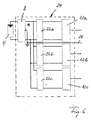
- Fig. 6 schematically shows the structure of a three-phase inverter 24. This structure is obtained by providing for each phase of the network 7, a separate second intermediate circuit 22a, 22b and 22c, according to Fig. 1 each with an internal freewheeling diode is provided. In addition, a corresponding one to each second intermediate circuit 22a, 22b and 22c Fig. 1 connected bridge branch 10a, 10b and 10c, which supplies power to one of the three phases of the network. A line 25 leads from the connection point 14 to the neutral conductor of the network 7, not shown here.
Applications Claiming Priority (1)
| Application Number | Priority Date | Filing Date | Title |
|---|---|---|---|
| DE102007038960A DE102007038960A1 (de) | 2007-08-14 | 2007-08-14 | Wechselrichter |
Publications (2)
| Publication Number | Publication Date |
|---|---|
| EP2026456A1 true EP2026456A1 (fr) | 2009-02-18 |
| EP2026456A8 EP2026456A8 (fr) | 2009-04-08 |
Family
ID=40087522
Family Applications (1)
| Application Number | Title | Priority Date | Filing Date |
|---|---|---|---|
| EP08012566A Withdrawn EP2026456A1 (fr) | 2007-08-14 | 2008-07-11 | Onduleur |
Country Status (4)
| Country | Link |
|---|---|
| US (1) | US7813153B2 (fr) |
| EP (1) | EP2026456A1 (fr) |
| KR (1) | KR20090017427A (fr) |
| DE (1) | DE102007038960A1 (fr) |
Families Citing this family (11)
| Publication number | Priority date | Publication date | Assignee | Title |
|---|---|---|---|---|
| ES2541772T3 (es) * | 2006-07-31 | 2015-07-24 | Ingeteam Power Technology, S.A. | Circuito inversor monofásico para acondicionar y convertir energía eléctrica de corriente continua en energía eléctrica de corriente alterna |
| US8864855B2 (en) * | 2008-10-01 | 2014-10-21 | Societe Bic | Portable hydrogen generator |
| US7990743B2 (en) * | 2009-10-20 | 2011-08-02 | General Electric Company | System and method for decreasing solar collector system losses |
| US7855906B2 (en) | 2009-10-26 | 2010-12-21 | General Electric Company | DC bus voltage control for two stage solar converter |
| WO2011095610A2 (fr) * | 2010-02-05 | 2011-08-11 | Commissariat à l'énergie atomique et aux énergies alternatives | Systeme d'equilibrage de charge pour batteries |
| US8050062B2 (en) | 2010-02-24 | 2011-11-01 | General Electric Company | Method and system to allow for high DC source voltage with lower DC link voltage in a two stage power converter |
| US9088224B2 (en) | 2010-07-21 | 2015-07-21 | Lihua Chen | Variable voltage converter with stabilized output voltage |
| US9118213B2 (en) | 2010-11-24 | 2015-08-25 | Kohler Co. | Portal for harvesting energy from distributed electrical power sources |
| KR101522414B1 (ko) * | 2013-12-31 | 2015-05-21 | 주식회사 효성 | Z-소스 회로장치 |
| US10495145B2 (en) | 2016-04-22 | 2019-12-03 | Ingersoll-Rand Company | Active magnetic bearing controller |
| EP3675345A1 (fr) * | 2018-12-31 | 2020-07-01 | Solaredge Technologies Ltd. | Convertisseur de puissance à condensateurs équilibrées |
Citations (7)
| Publication number | Priority date | Publication date | Assignee | Title |
|---|---|---|---|---|
| DE19642522C1 (de) | 1996-10-15 | 1998-04-23 | Dietrich Karschny | Wechselrichter |
| DE19732218C1 (de) | 1997-07-26 | 1999-03-18 | Dirk Schekulin | Transformatorlose Wechselrichter-Schaltungsanordnung |
| DE10221592A1 (de) | 2002-05-15 | 2003-12-04 | Fraunhofer Ges Forschung | Wechselrichter sowie Verfahren zum Umwandeln einer elektrischen Gleichspannung in einen Wechselstrom |
| DE10225020A1 (de) | 2002-06-06 | 2003-12-24 | Sma Regelsysteme Gmbh | Schaltungsanordnung, Verfahren zur Wechselstromerzeugung |
| DE102004030912B3 (de) | 2004-06-25 | 2006-01-19 | Sma Technologie Ag | Verfahren zum Umwandeln einer elektrischen Gleichspannung einer Gleichspannungsquelle, insbesondere einer Photovoltaik-Gleichspannungsquelle in eine Wechselspannung |
| DE102004037446A1 (de) | 2004-08-02 | 2006-06-01 | Conergy Ag | Trafoloser Wechselrichter,für die Umwandlung von solrarem Gleichstrom in sinusförmigen Wechselstrom zur Netzeinspeisung |
| US20070047277A1 (en) | 2005-08-29 | 2007-03-01 | Industrial Technology Research Institute | Transformerless power conversion circuit for grid-connected power generation systems |
Family Cites Families (9)
| Publication number | Priority date | Publication date | Assignee | Title |
|---|---|---|---|---|
| US5781419A (en) * | 1996-04-12 | 1998-07-14 | Soft Switching Technologies, Inc. | Soft switching DC-to-DC converter with coupled inductors |
| US5883793A (en) * | 1998-04-30 | 1999-03-16 | Lucent Technologies Inc. | Clamp circuit for a power converter and method of operation thereof |
| US6055161A (en) * | 1999-04-12 | 2000-04-25 | Lincoln Global, Inc. | Switching type power supply for arc welding |
| US6349044B1 (en) * | 1999-09-09 | 2002-02-19 | Virginia Tech Intellectual Properties, Inc. | Zero voltage zero current three level dc-dc converter |
| US7130205B2 (en) * | 2002-06-12 | 2006-10-31 | Michigan State University | Impedance source power converter |
| JP4597626B2 (ja) * | 2004-03-01 | 2010-12-15 | 株式会社ダイヘン | アーク加工用電源装置及びインバータ電源装置 |
| DE102005024465B4 (de) * | 2005-05-24 | 2010-01-07 | Hantschel, Jochen, Dipl.-Ing. (FH) | Schaltungsanordnung und Steuerungsverfahren für einen Umrichter |
| US7319313B2 (en) * | 2005-08-10 | 2008-01-15 | Xantrex Technology, Inc. | Photovoltaic DC-to-AC power converter and control method |
| DE102006012164B4 (de) * | 2005-12-23 | 2009-12-17 | Fraunhofer-Gesellschaft zur Förderung der angewandten Forschung e.V. | Schaltungsanordnung zur Erzeugung einer Wechselspannung oder eines Wechselstroms |
-
2007
- 2007-08-14 DE DE102007038960A patent/DE102007038960A1/de not_active Withdrawn
-
2008
- 2008-07-11 EP EP08012566A patent/EP2026456A1/fr not_active Withdrawn
- 2008-07-31 US US12/221,082 patent/US7813153B2/en not_active Expired - Fee Related
- 2008-08-11 KR KR1020080078284A patent/KR20090017427A/ko not_active Application Discontinuation
Patent Citations (7)
| Publication number | Priority date | Publication date | Assignee | Title |
|---|---|---|---|---|
| DE19642522C1 (de) | 1996-10-15 | 1998-04-23 | Dietrich Karschny | Wechselrichter |
| DE19732218C1 (de) | 1997-07-26 | 1999-03-18 | Dirk Schekulin | Transformatorlose Wechselrichter-Schaltungsanordnung |
| DE10221592A1 (de) | 2002-05-15 | 2003-12-04 | Fraunhofer Ges Forschung | Wechselrichter sowie Verfahren zum Umwandeln einer elektrischen Gleichspannung in einen Wechselstrom |
| DE10225020A1 (de) | 2002-06-06 | 2003-12-24 | Sma Regelsysteme Gmbh | Schaltungsanordnung, Verfahren zur Wechselstromerzeugung |
| DE102004030912B3 (de) | 2004-06-25 | 2006-01-19 | Sma Technologie Ag | Verfahren zum Umwandeln einer elektrischen Gleichspannung einer Gleichspannungsquelle, insbesondere einer Photovoltaik-Gleichspannungsquelle in eine Wechselspannung |
| DE102004037446A1 (de) | 2004-08-02 | 2006-06-01 | Conergy Ag | Trafoloser Wechselrichter,für die Umwandlung von solrarem Gleichstrom in sinusförmigen Wechselstrom zur Netzeinspeisung |
| US20070047277A1 (en) | 2005-08-29 | 2007-03-01 | Industrial Technology Research Institute | Transformerless power conversion circuit for grid-connected power generation systems |
Non-Patent Citations (4)
| Title |
|---|
| PENG F Z ED - INSTITUTE OF ELECTRICAL AND ELECTRONICS ENGINEERS: "Z-source inverter", CONFERENCE RECORD OF THE 2002 IEEE INDUSTRY APPLICATIONS CONFERENCE. 37TH IAS ANNUAL MEETING . PITTSBURGH, PA, OCT. 13 - 18, 2002; [CONFERENCE RECORD OF THE IEEE INDUSTRY APPLICATIONS CONFERENCE. IAS ANNUAL MEETING], NEW YORK, NY : IEEE, US, vol. 2, 13 October 2002 (2002-10-13), pages 775 - 781, XP010609970, ISBN: 978-0-7803-7420-1 * |
| POH CHIANG LOH ET AL: "Z-Source B4 Inverters", POWER ELECTRONICS SPECIALISTS CONFERENCE, 2007. PESC 2007. IEEE, IEEE, PISCATAWAY, NJ, USA, 17 June 2007 (2007-06-17), pages 1363 - 1369, XP031218483, ISBN: 978-1-4244-0654-8 * |
| TUCKEY A M ET AL: "A low-cost inverter for domestic fuel cell applications", 33RD.ANNUAL IEEE POWER ELECTRONICS SPECIALISTS CONFERENCE. PESC 2002. CONFERENCE PROCEEDINGS. CAIRNS, QUEENSLAND, AUSTRALIA, JUNE 23 - 27, 2002; [ANNUAL POWER ELECTRONICS SPECIALISTS CONFERENCE], NEW YORK, NY : IEEE, US, vol. 1, 23 June 2002 (2002-06-23), pages 339 - 346, XP010596110, ISBN: 978-0-7803-7262-7 * |
| YI HUANG ET AL: "Source Inverter for Residential Photovoltaic Systems", IEEE TRANSACTIONS ON POWER ELECTRONICS, IEEE SERVICE CENTER, PISCATAWAY, NJ, US, vol. 21, no. 6, 1 November 2006 (2006-11-01), pages 1776 - 1782, XP011142834, ISSN: 0885-8993 * |
Also Published As
| Publication number | Publication date |
|---|---|
| US20090046491A1 (en) | 2009-02-19 |
| DE102007038960A1 (de) | 2009-02-26 |
| EP2026456A8 (fr) | 2009-04-08 |
| KR20090017427A (ko) | 2009-02-18 |
| US7813153B2 (en) | 2010-10-12 |
Similar Documents
| Publication | Publication Date | Title |
|---|---|---|
| EP2027647B1 (fr) | Dispositif d'alimentation électrique dans un réseau d'alimentation électrique et convertisseur de tension continue destiné à un tel dispositif | |
| EP2026457A1 (fr) | Onduleur avec deux circuits intermédiaires | |
| EP2030299B1 (fr) | Onduleur destiné à injecter de l'énergie électrique dans un réseau de distribution d'énergie | |
| EP2067230B1 (fr) | Dispositif destiné à l'alimentation en énergie électrique d'un réseau d'alimentation en énergie et convertisseur pour un tel dispositif | |
| EP2026456A1 (fr) | Onduleur | |
| EP2023475B1 (fr) | Inversion pour une source de tension continue reliée à la terre, en particulier un générateur photovoltaïque | |
| EP3014725B1 (fr) | Dispositif accumulateur d'énergie doté d'un circuit d'alimentation en tension continue et procédé pour fournir une tension continue à partir d'un dispositif accumulateur d'énergie | |
| EP2309639B1 (fr) | Onduleur capable de puissance réactive | |
| EP2719051A2 (fr) | Convertisseur survolteur | |
| DE102012216691A1 (de) | Stromrichterschaltung und Verfahren zur Steuerung der Stromrichterschaltung | |
| DE102013221830A1 (de) | Ladeschaltung für eine Energiespeichereinrichtung und Verfahren zum Laden einer Energiespeichereinrichtung | |
| DE102011018357A1 (de) | Gleichspannungswandler | |
| EP3332466B1 (fr) | Onduleur inverseur de polarité et avec capacité de puissance réactive ainsi que procédé d'inversion de polarité | |
| DE102013105098A1 (de) | Integrierter Solar-/Batteriewechselrichter | |
| EP3257145A1 (fr) | Convertisseur cc/cc avec condensateur flottant | |
| DE102014012028A1 (de) | Vorrichtung und ein Verfahren zum Laden oder Entladen eines elektrischen Energiespeichers mit beliebigen Betriebsspannungen | |
| DE102013207894A1 (de) | Elektrische Schaltung | |
| EP2523339B1 (fr) | Procédé et dispositif de génération d'énergie au moyen d'une installation photovoltaïque avec une compensation d'énergie entre les branches des générateurs photovoltaïques | |
| EP2826126B1 (fr) | Dispositif électronique de puissance comportant une symétrisation d'un n ud de tension dans le circuit intermédiaire | |
| DE202010007787U1 (de) | Gleichspannungssteller | |
| DE102007029767B3 (de) | Wechselrichter | |
| DE102015113071B4 (de) | Potentialverschiebende Halbbrücke, Polwender und blindleistungsfähiger Wechselrichter sowie Polwendeverfahren | |
| DE102011115728A1 (de) | Verfahren zum Betreiben eines Wechselrichters und Wechselrichterschaltung | |
| DE19711018A1 (de) | Gleichspannungs-Transformator |
Legal Events
| Date | Code | Title | Description |
|---|---|---|---|
| PUAI | Public reference made under article 153(3) epc to a published international application that has entered the european phase |
Free format text: ORIGINAL CODE: 0009012 |
|
| AK | Designated contracting states |
Kind code of ref document: A1 Designated state(s): AT BE BG CH CY CZ DE DK EE ES FI FR GB GR HR HU IE IS IT LI LT LU LV MC MT NL NO PL PT RO SE SI SK TR |
|
| AX | Request for extension of the european patent |
Extension state: AL BA MK RS |
|
| RIN1 | Information on inventor provided before grant (corrected) |
Inventor name: ZINN, MATTHIAS Inventor name: SCHEUERMANN, JAN Inventor name: GERLACH, ANN-KATRIN Inventor name: BLUMENSTEIN, FELIX Inventor name: FRIEBE, JENS Inventor name: ZACHARIAS, PETER, PROF. DR. |
|
| 17P | Request for examination filed |
Effective date: 20090810 |
|
| AKX | Designation fees paid |
Designated state(s): AT BE BG CH CY CZ DE DK EE ES FI FR GB GR HR HU IE IS IT LI LT LU LV MC MT NL NO PL PT RO SE SI SK TR |
|
| 17Q | First examination report despatched |
Effective date: 20091117 |
|
| STAA | Information on the status of an ep patent application or granted ep patent |
Free format text: STATUS: THE APPLICATION IS DEEMED TO BE WITHDRAWN |
|
| 18D | Application deemed to be withdrawn |
Effective date: 20100528 |